FANUC Series 30i/31i-A Specifying Tilted Working Plane Based on the Tool Axis Direction Additional Manual Page 3
Additional Manual
Ed.
App
rov.
Page
Name No.
Date Person
Contents
Date
FANUC Series 30i
/
31i-
A
Specifying Tilted Working Plane
Based on the Tool Axis Direction
A
-79976E
Feb.03.’05
3
/
14
FANUC LTD.
Person
Format
Format
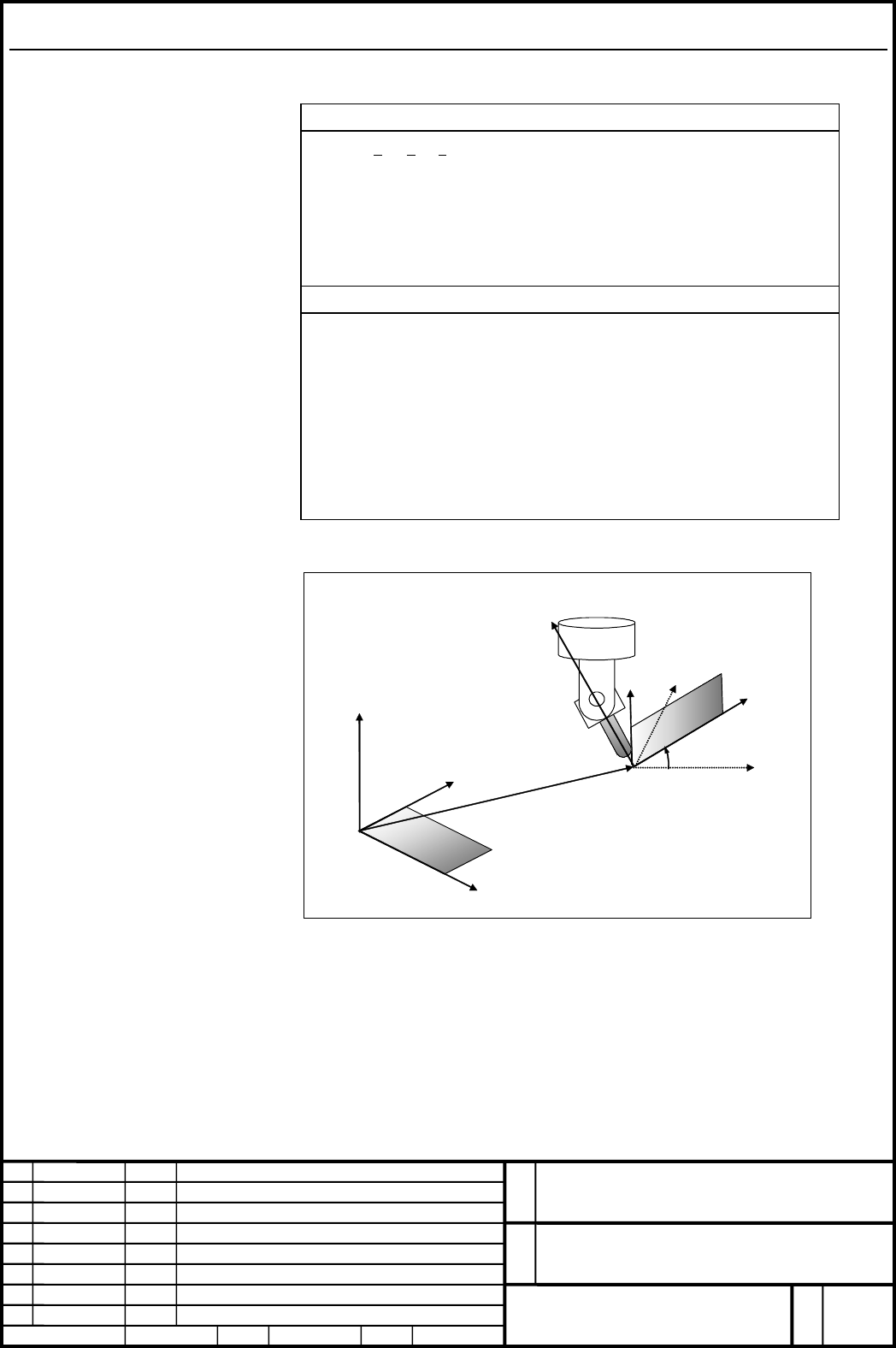
G68.3 X x
0
Y y
0
Z z
0
Rα ; Set a feature coordinate system.
G69 ; Cancel feature coordinate system setting (M
series).
G69.1; Cancel feature coordinate system setting (T
series).
Explanation of symbols
X,Y,Z : Origin of a feature coordinate system (absolute)
When 1 address or 2addresses are omitted in X, Y, Z, alarm
PS5457 is issued.
When 3 addresses are omitted, the current position becomes
the origin of the feature coordinate system.
R : Angular displacement about the Z-axis in the feature
coordinate system.
The default is 0°.
Coordinate system origin
shift (xo,yo,zo)
X
c
Y
c
Zc
Workpiece coordinate
system X-Y-Z
Feature coordinate system
Xc-Yc-Zc
X
Y
Z
α
Fig. (b) G68.3 command
Contents Summary of FANUC Series 30i/31i-A Specifying Tilted Working Plane Based on the Tool Axis Direction Additional Manual
- Page 1FANUC Series 30i/31i -A Specifying a Tilted Working Plane Based on the Tool Axis Direction Specifications FANUC Series 30i/31i-A Name Specifying Tilted Working Plane Based on the Tool Axis Direction No. A-79976E Ed. Date Date Person Feb.03.’05 Person Contents Approv. FANUC LTD. Page 1 / 14
- Page 21.1 SPECIFYING A TILTED WORKING PLANE BASED ON THE TOOL AXIS DIRECTION Overview By specifying G68.3, a coordinate system (feature coordinate system) where the tool axis direction is the +Z-axis direction can be automatically specified. When a feature coordinate system is used, a program for cutting
- Page 3Format Format G68.3 X x0 Y y0 Z z0 Rα ; Set a feature coordinate system. G69 ; Cancel feature coordinate system setting (M series). G69.1; Cancel feature coordinate system setting (T series). Explanation of symbols X,Y,Z : Origin of a feature coordinate system (absolute) When 1 address or 2addresses
- Page 4Explanation - Feature coordinate system By specifying G68.3, a feature coordinate system with the tool axis direction being the +Z-axis direction can be created. The tool axis direction means the tool axis direction based on the rotation axis position reached by automatic operation or manual operati
- Page 5Vertical axis direction: P Zc Z-axis of feature coordinate system (Tool axis direction: T) Yc Xc Y-axis of feature X-axis of feature coordinate coordinate system system Fig. (c) Determination of a feature coordinate system When the tool axis direction vector ( T ) is parallel with the vertical axis
- Page 6- Angular displacement R Angular displacement R is positive when a rotation is made clockwise viewed in the Z-axis direction of the feature coordinate system. The range of angular displacement R is: 0.0° ≤ R ≤ 360.0°. - Machine of table rotation type On a machine of table rotation type, the tool dir
- Page 7- Example of operation An example of operation on a machine of tool rotation type is given below. The machine configuration is "BC type reference tool axis Z-axis". BC type tool axis Z-axis (Axes are intersecting.) C: 1st rotation axis (master) B: 2nd rotation axis (slave) Tool holder offset value =
- Page 8Machine operation by sample program 1 Z N3 command Y Workpiece coorditate system X X- Y- Z N4 command Zc Yc Feat ur e coor di nat e syst em Xc- Yc- Zc Xc N5 command Z N7 command Y Workpiece coorditate system X- Y- Z X N3 block: Tilts the tool. N4 block: Sets a feature coordinate system where the too
- Page 9Machine operation by sample program 2 Z N3 command Y Workpiece coorditate system X- Y- Z X Z N4 command Y X Zc N5 command Yc Feat ur e coor di nat e syst em Xc- Yc- Zc Xc Z N6 command Y Workpiece coorditate system X- Y- Z X N3 block: Performs tool length compensation in the workpiece coordinate syst
- Page 101.2 Multiple G68.3 After the tool axis direction is changed in G68.3 mode, by specifying G68.3, a new feature coordinate system where the tool axis direction is the +Z-axis direction can be specified. - Origin of a feature coordinate system In the case of specifying G68.3 in G68.3 mode, the origin o
- Page 11Machine operation by sample program 3 Z N3 command Y Yc X Xc Zc Feat ur e coor di nat e syst em Xc- Yc- Zc N4 command Z Y Yc X Xc Zc N5 command Z Y Yc Xc Zc X N7 command Z Y Yc X Zc Xc N3 block: Sets a feature coordinate system where the tool axis direction is the Z- axis direction. N4 block: Change
- Page 12Restrictions The restrictions imposed on three-dimensional coordinate conversion also apply to the tilted working plane command. The following presents the restrictions to bear in mind in particular: Tool length compensation When tool length compensation direct is X-axis direction or Y-axis directio
- Page 13Parameters 12321 Normal axis direction [Input type] Parameter input [Data type] Integerpath [Valid data range] 0-3 For longitude or latitude direction feed in the 5-axis machining manual feed mode, this parameter sets the axis parallel to the normal direction. 1 : Positive (+) X-axis direction 2 : P
- Page 14Alarm and message Number Message Description PS5457 G68.2/G68.3 FORMAT ERROR A G68.2/G68.3 format error occurred. PS5459 MACHINE PARAMETER - A machine configuration parameter (parameter No.19665 INCORRECT to 19667, No. 19680 to 19714, or No. 12321) is incorrect. - The axis set in parameter No. 19681