Fanuc PMC-Model SD7 Programming Manual Additional Manual Page 237
Additional Manual
FANUC PMC-MODEL SD7
Programming Manual
01 01.11.26
Hanaoka
New
A-78550E
EDIT DATE DESIG.
DESCRIPTION
236/
316
TITLE
DRAW.NO.
5.3.3 Alarm Screen (ALARM)
If an alarm condition occurs in the PMC, pressing the [PMC] soft key from
the NC system displays the following alarm message instead of the PMC
basic menu. The soft keys displayed on this screen remain the same as on
the PMC basic module screen. In addition, character string “ALM” appears.
If the alarm condition is fatal, no sequence program will be executed.
For an explanation of the alarm messages displayed on this screen, see
APPENDIX B, “ALARM MESSAGE LIST”.
Contents Summary of Fanuc PMC-Model SD7 Programming Manual Additional Manual
- Page 1TECHNICAL REPORT NO.TMN 01/179E Date 2001.11.27 General Manager of Software Laboratory FANUC PMC-MODEL SD7 Programming Manual 1. Communicate this report to: Your information GE Fanuc-N, GE Fanuc-E FANUC Robotics MILACRON Machine tool builder Sales agency End user 2. Summary for Sales Documents This
- Page 2FANUC PMC-MODEL SD7 Programming Manual TITLE FANUC PMC-MODEL SD7 Programming Manual DRAW.NO. 01 01.11.26 Hanaoka New A-78550E EDIT DATE DESIG. DESCRIPTION 1/316�
- Page 3Preface This manual covers the specifications and the instructions and operations used for programming with the following devices. Product name Applicable CNC FANUC PMC-MODEL FANUC Series 16i-MODEL B SD7(PMC-SD7) (Series 16i-B) FANUC Series 160i-MODEL B (Series 160i-B) FANUC Series 18i-MODEL B (Seri
- Page 4FANUC Series 16i/18i/21i/160i/180i/210i-MODEL B B-63523EN-1 Connection Manual (Function) This product can be programmed using the following software. This software provides with a lot of help documents which contain the information of PMC-SD7. Please also refer to these help documents. Cimplicity Ma
- Page 5CONTENTS CONTENTS ...................................................................................................... 4 1 OVERVIEW .............................................................................................. 10 1.1 System Configuration............................................
- Page 63.5 Bit Operations .......................................................................................................................64 3.5.1 AND_(type)/OR_(type).............................................................................................................65 3.5.2 XOR_(type) ....
- Page 73.10.6 PMC_WINDOW ....................................................................................................................135 3.10.7 PMC_EXIN............................................................................................................................137 3.10.8 PMC_AXCTL ..
- Page 84.6 IL Data Move Functions......................................................................................................187 4.6.1 Move Data..............................................................................................................................188 4.6.2 Swap Data .......
- Page 95.4.1 Overview................................................................................................................................255 5.4.2 Input PMC Parameters From MDI Panel .................................................................................255 5.4.3 Setting and Display s
- Page 10TITLE FANUC PMC-MODEL SD7 Programming Manual DRAW.NO. 01 01.11.26 Hanaoka New A-78550E EDIT DATE DESIG. DESCRIPTION 9/316�
- Page 111 OVERVIEW 1.1 System Configuration The PMC-SD7 is used to create and execute sequence programs conforming to the IEC61131-3 standard. The system requires the following hardware and software (development software, etc.). CNC PC Built-in PMC Hardware Ethernet RS-232-C Program Machine tool DI/DO • Seq
- Page 121.2 PMC Basic Configuration The basic configuration of the PMC is as shown below. CNC CNC control Built-in PMC unit Internal Sequence External Machine tool I/O I/O Internal relay There are two types of PMC: • Those using programming that conforms with IEC61131-3, as described in this manual • Those
- Page 131.3 Contents of this Manual 1. Overview 2. Specifications explains the PMC specifications, program structuring, data type, and references. 3. The LD Instruction Group explains the LD programming instructions that can be used with the PMC. 4. The IL Instruction Group explains the IL programming instr
- Page 142 SPECIFICATIONS 2.1 Specifications of PMC The following table lists the specifications of the PMC-SD7. Type of PMC PMC-SD7 Series 16i/160i/18i/180i/21i/210i-B Programming language LD (Ladder Diagram) IL(Instruction List) Number of ladder levels 2 Ladder execution cycle 8 ms Instruction processing t
- Page 15Programming Language LD and IL are supported as the programming language. About LD Logic Ladder Diagram (LD) logic is one of five programming languages specified by the IEC 61131-3 standard. This graphical language is likely the most popular control language in use today. LD logic is represented as
- Page 16Fig. 2.1 About priority of execution. 8ms 8ms 8ms 8ms 7ms 7ms 7ms 1st level Division 1 Division 1 2nd level Division 2 Division n System etc The 1st level sequence part operates every 8 ms (high-speed sequential operation). If the 1st level sequence part is long, the total operating time, including
- Page 17deceleration, external deceleration, skip, measuring position arrival and feed hold signals. Instruction Processing Time Relay instructions are processed at high speed, such that it requires 0.033 us to execute one step. Program Size A FANUC PMC program is contained in the flash memory of the CNC. T
- Page 182.2 Data Types This section explains the data types which can be used with PMC programs. The PMC can use the basic IEC61131-3 data types shown below. Keyword Data type Bit count Range BOOL Boolean 1 The value obtained with this data type is either 0 (false) or 1 (true). INT 16-bit integer 16 Range o
- Page 192.3 References 2.3.1 User references This section explains the references which can be used in a PMC program. The following lists the valid range of PMC addresses. Name Range Size Attribute Remarks Corresponding PMC-SB7 references %I 1- 1024 1-bit (BOOL type) Read-only Input from I/O Link 1st channe
- Page 20Note 1. These references are used for 2nd channel of I/O Link. I/O link expansion option is necessary. 2. This area is reserved for PMC. I/O can not be assigned in it. Don’t use it in sequence program. 3. This area contains PMC reserve. Actual available references depend on the configuration of CNC
- Page 212.3.2 System references The following explains the system references used by the PMC control software. Address Name Explanation %S601 #ALW_OFF Always OFF signal. %S602 #ALW_ON Always ON signal. %S606 #T_200MS 200 ms cycle signal. (104 ms ON, 96 ms OFF) %S607 #T_SEC 1 sec cycle signal. (504 ms ON, 49
- Page 222.3.2.1 RUN to STOP Transition Signal, STOP to RUN Transition Signal and RUN Status Signal (i) “STOP to RUN transition signal” (%ST57) When a STOP to RUN event is detected on system software, this signal will be turned on during the 1st scan of LADDER program after LADDER started. This signal has in
- Page 23(ii) “RUN to STOP transition signal” (%ST58) When a RUN to STOP event is detected on system software, this signal will be turned off during the last scan of LADDER program before LADDER stopped. This signal has individual status corresponding the scan of each LADDER execution level. This signal is c
- Page 242.3.3 Message display reference Function PMC can display messages on the CNC screen using the CNC external operator and alarm message functions. An external alarm message can also be specified with its message number to place the CNC in the alarm state. To use this function, create message data usin
- Page 25an alarm message or 255 (255 bytes) for an operator message. An alphanumeric character requires 1 byte. For other special characters including half-size kana characters and kanji characters (full-size characters), note the following: a half-size kana character requires 2 bytes, a kanji character req
- Page 26number. NOTE If a nonexistent path number such as 0 is specified, no message is displayed. Setting Message Data Input message data characters using a programmer. Kana and kanji characters can be input as numeric data with a special symbol "@". See the later section "Inputting kana and kanji characte
- Page 27modified. For numeric values to be made variable during execution, define a memory address in message data and set numeric data in the memory using the sequence program to display any numeric data. Using this function, data such as a tool number that frequently changes during automatic operation can
- Page 28NOTES 1) The total number of digits of the integer and fraction parts must not exceed 8. 2) For erroneous numeric data such as data consisting of more than eight digits, a blank is displayed. 3) The numeric data of address of the BYTE boundary such as %I1, %I9 or %I17 is displayed. When the address
- Page 29Input kanji characters using their numeric codes by referencing the kanji, hiragana, and special character code table. One kanji character requires 4 bytes. 3 Example Inputting ATC ? OK: TITLE FANUC PMC-MODEL SD7 Programming Manual DRAW.NO. 01 01.11.26 Hanaoka New A-78550E EDIT DATE DESIG. DESCRIPTI
- Page 30Character code table NOTES 1 To define character @, input @40...@. @ 2 To define a line feed of a screen display message, input @0A@ at the end of data. 3 For numeric code input, code @ requires 1 byte. When a character, for example, a space is input using its numeric code (20), 1 byte for "2" and
- Page 313 LD INSTRUCTION GROUP The following explains the Ladder Diagram(LD) instructions used by a PMC sequence program. PMC Instruction Set Number Class Instruction 1. Contact, Coil --| |--, --|/|--, |+|--- --( ), --(/), --(S), --(R),--(+) 2. Timer, counter ONDTR_, TMR_, OFDT_, UPCTR_, DNCTR_ 3. Math oper
- Page 323.1 Contacts & Coils Contacts Instruction Function Data type --| |-- Normally open BOOL contact (A contact) --|/|-- Normally close BOOL contact (B contact) |+|--- Continuous contact BOOL Coils Instruction Function Data type --( )-- Coil BOOL --(/)-- Reverse-wound coil BOOL --(S)-- Set coil BOOL --(R
- Page 33Example While %I00001 is set to ON, but %I00002 is OFF, %Q00001 is set to ON. %I00001 % I00002 %Q00001 3.1.3 Coils Function While the coil is receiving a power flow, it sets the corresponding reference to ON. Format ??????? 3.1.4 Reverse-wound coils Function While the coil is not receiving a power f
- Page 343.1.5 Setting coil (SET) Function While the coil is receiving a power flow, it sets the corresponding reference to ON. This ON state is maintained until reset by the reset coil (RESET), described below. Format ??????? 3.1.6 Reset coil (RESET) Function While the coil is receiving a power flow, it set
- Page 353.1.7 Continuous contacts & continuous coils Function Indicates the continuation of a ladder when the ladder for one net can not be described within 20 elements. Format Example %I00001 REL ABS INT %R00010 IN Q %R00110 %I00011 %I00012 %I00013 %I00014 %I00029 %I00032 %I00033 %Q00010 Element 1 Element
- Page 363.2 Timers & Counters Timers Instruction Function Parameter Data type Controlled I/O ONDTR_(unit) Integrated on ADRS, PV ADRS = one- EN, ENO, delay timer dimensional R WORD array of 3 words PV = INT TMR_(unit) On delay ADRS, PV ADRS = one- EN, ENO timer dimensional WORD array of 3 words PV = INT OFD
- Page 373.2.1 ONDTR Function The retentive On-Delay Stopwatch Timer (ONDTR) increments while it receives power flow and holds its value when power flow stops. When this function first receives power flow, it starts accumulating time (Current Value (CV)). When this timer is encountered in the ladder logic, i
- Page 38Parameters Parameter Data type Meaning ADRS one- ADRS is the beginning address of a three-word dimensional WORD array: WORD Word 1: Current value (CV) array of 3 words Word 2: Preset value (PV) Word 3: Control word EN BOOL Timer start R BOOL Timer reset PV INT Set time (Preset Value) The time requir
- Page 393.2.2 TMR Function The On-Delay Timer (TMR) increments while it receives power flow and resets to zero when power flow stops. The timer passes power after the specified interval PV (Preset Value) has elapsed, as long as power is received. When the On Delay Timer function receives power flow, the tim
- Page 40WORD array of 3 word WORD array: words Word 1: Current value (CV) Word 2: Preset value (PV) Word 3: Control word EN BOOL Timer start PV INT Set time (Preset Value) The time required to actually reach time up will be this value to which the set units are applied. ENO BOOL Time up TITLE FANUC PMC-MODE
- Page 41Memory Type Memory Flow %I* %Q* %M* %S* %R Constant Omissible ADRS o o EN o o o o o PV o o o o o o ENO o o o Note o Note Only %SK can be specified. Example While REL is OFF, if DO_DWL is turned ON, DWELL is also turned ON. (The latch circuit causes the ON state to be maintained even if DO_DWL is sub
- Page 423.2.3 OFDT Function The Off-Delay Timer (OFDT) increments while power flow is off, and the timer's Current Value (CV) resets to zero when power flow is on. OFDT passes power until the specified interval PV (Preset Value) has elapsed. When OFDT first receives power flow, CV is set to zero and the tim
- Page 43Parameters Parameter Data type Meaning ADRS one-dimensional ADRS is the beginning address of a three-word WORD array of WORD array: 3 words Word 1: Current value (CV) Word 2: Preset value (PV) Word 3: Control word EN BOOL Timer start PV INT Set time (Preset Value) The time required to actually reach
- Page 443.2.4 UPCTR Function The Up Counter (UPCTR) function counts up to the Preset Value (PV). The range is 0 to +32,767 counts. When the Current Value (CV) of the counter reaches 32,767, it remains there until reset. When the UPCTR reset is ON, CV resets to 0. Each time the power flow input transitions f
- Page 45Memory Type Memory Flow %I* %Q* %M* %S* %R Constant Omissible ADRS o o EN o o o o o R o o o o o PV o o o o o o ENO o o o Note o Note Only %SK can be specified. Example Every time %I00001 goes from OFF to ON, the count is incremented by one. Once CV exceeds 100, %Q00001 is set to ON. (Also, at this t
- Page 463.2.5 DNCTR Function The Down Counter (DNCTR) function counts down from a preset value. The minimum Preset Value (PV) is zero; the maximum present value is +32,767 counts. When the Current Value (CV) reaches the minimum value, -32,768, it stays there until reset. When DNCTR is reset, CV is set to PV
- Page 47Memory Type Memory Flow %I* %Q* %M* %S* %R Constant Omissible ADRS o o EN o o o o o R o o o o o PV o o o o o o o ENO o o o Note o Note Only %SK can be specified. Example Every time %I00001 goes from OFF to ON, the count is decremented by one. Once the value of CV falls below 0, %Q00001 is set to ON.
- Page 483.3 Math Operations Math operation functions Instruction Function Parameters Data type Controlled I/O ADD_(type) Addition IN1, IN2, Q ANY_INT EN, ENO SUB_(type) Subtraction IN1, IN2, Q ANY_INT EN, ENO MUL_(type) Multiplication IN1, IN2, Q ANY_INT EN, ENO DIV_(type) Division IN1, IN2, Q ANY_INT EN, E
- Page 493.3.1 ADD_(type)/SUB_(type)/MUL_(type)/DIV_(type) Function When EN is set to ON and is receiving the power flow, ADD, SUB, MUL, and DIV perform, on input parameters IN1 and IN2, addition (IN1 + IN2), subtraction (IN1 - IN2), multiplication (IN1 X IN2), and division (IN1 ÷ IN2), respectively. The res
- Page 50Format ADD (EN) (type) (ENO) ??????? IN1 Q ??????? ??????? IN2 SUB MUL DIV Parameters Parameter Data type Meaning EN BOOL Execution of operation IN1 ANY_INT Input data 1 IN2 ANY_INT Input data 2 ENO BOOL Normal end flag (set to OFF upon an overflow) Q ANY_INT Result Memory Type Memory Flow %I* %Q* %
- Page 51Example When %I00001 is set to ON, 1 is added to the value of %R00001, 95, to give an output of 96 to %R00010. %Q00001 is set to ON, and notification of the operation ending without an overflow is posted. %I00001 %Q00001 ADD INT %R00001 IN1 Q %R00010 +00095 CONST IN2 +00001 TITLE FANUC PMC-MODEL SD7
- Page 523.3.2 MOD_(type) Function When EN is set to ON and is receiving the power flow, MOD performs, on input parameters IN1 and IN2, division (IN1 ÷ IN2) and outputs the remainder to output parameter Q. IN1, IN2, and Q must all be of the same data type. Q will have the same sign as IN1. When the operation
- Page 53Memory Type Memory Flow %I* %Q* %M* %S* %R Constant Omissible EN o o o o o IN1 o o o o o o IN2 o o o o o o ENO o o o Note o Q o o Note o Note Only %SK can be specified. Example When %I00001 is set to ON, division (-17 ÷ 6) is performed and the remainder - 5 is output to %R00010. %I00001 %Q00001 MOD
- Page 543.3.3 ABS_(type) Function When EN is set to ON and is receiving the power flow, ABS takes the absolute value of input parameter IN and outputs it to output parameter Q. ABS_(type) instructions Name Explanation ABS_INT The absolute value of INT data ABS_DINT The absolute value of DINT data Format ABS
- Page 55Example When %I00010 is set to ON, the absolute value of -1234, namely 1234, is output to %R00020. %I00010 %Q00011 ABS INT CONST IN Q %R00020 -1234 1234 TITLE FANUC PMC-MODEL SD7 Programming Manual DRAW.NO. 01 01.11.26 Hanaoka New A-78550E EDIT DATE DESIG. DESCRIPTION 54/316�
- Page 563.3.4 SQRT_(type) Function When EN is set to ON and is receiving the power flow, SQROOT takes the square root of input parameter IN and outputs it to output parameter Q. IN and Q must both be of the same data type. SQRT_(type) instructions Name Explanation SQRT_INT The square root of INT data SQRT_U
- Page 57Example When %I00010 is set to ON, the square root of the value of %R00100 is output to %R00200. %I00010 %Q00011 SQRT INT %R00100 IN Q %R00200 TITLE FANUC PMC-MODEL SD7 Programming Manual DRAW.NO. 01 01.11.26 Hanaoka New A-78550E EDIT DATE DESIG. DESCRIPTION 56/316�
- Page 583.4 Relational Operations Comparison instructions Instruction Function Parameter Data type Controlled I/O EQ_(type) Equal to IN1, IN2 BYTE, WORD, EN, Q DWORD, ANY_INT NE_(type) Not equal to IN1, IN2 BYTE, WORD, EN, Q DWORD, ANY_INT GT_(type) Greater than IN1, IN2 ANY_INT EN, Q (IN1 > IN2) GE_(type)
- Page 593.4.1 EQ_(type)/NE_(type) Function When EN is set to ON and is receiving the power flow, the signs of input parameters IN1 and IN2 are checked for equivalence (IN1 = IN2?) or non-equivalence (IN1≠ IN2?). When the result of the comparison is true, power is allowed to flow and Q is set to ON. IN1 and
- Page 60Parameters Parameter Data type Meaning EN BOOL Execution of comparison IN1 BYTE, WORD, Input data 1 DWORD, ANY_INT IN2 BYTE, WORD, Input data 2 DWORD, ANY_INT Q BOOL Result of comparison (set to ON when condition is satisfied) Memory Type Memory Flow %I* %Q* %M* %S* %R Constant Omissible EN o o o o
- Page 613.4.2 GT_(type)/GE_(type)/LT_(type)/LE_(type) Function When EN is set to ON and is receiving the power flow, the values of input parameters IN1 and IN2 are compared (IN1 > IN2?/IN1 ≥ IN2?/IN1 < IN2?/IN1 ≤ IN2?). If the result of the comparison is true, power is allowed to flow and Q is set to ON. IN
- Page 62Parameters Parameter Data type Meaning EN BOOL Execution of comparison IN1 ANY_INT Input data 1 IN2 ANY_INT Input data 2 Q BOOL Result of comparison (set to ON when condition is satisfied) Memory Type Memory Flow %I* %Q* %M* %S* %R Constant Omissible EN o o o o o IN1 o o o o o o IN2 o o o o o o Q o
- Page 633.4.3 RANGE_(type) Function When EN is set to ON and is receiving the power flow, RANGE compares input parameter IN with the range of L1 and L2. When L1 ≤ IN ≤ L2, or L2 ≤ IN ≤ L1, power is allowed to flow and Q is set to ON. L1, L2 and IN must all be of the same data type. RANGE_(type) instructions
- Page 64Memory Type Memory Flow %I* %Q* %M* %S* %R Constant Omissible EN o o o o o L1 o o o o o o L2 o o o o o o IN o o o o o o Q o o o Note o Note Only %SK can be specified. Example When %I00001 is set to ON, and the value of %R00100 is between 0 and 100, %Q00100 is set to ON. %I00001 RANGE INT %Q00100 CON
- Page 653.5 Bit Operations Bit operation functions Instruction Function Parameter Data type Controlled I/O AND_(type) Logical AND IN1, IN2, Q BYTE, WORD, DWORD EN, ENO OR_(type) Logical OR IN1, IN2, Q BYTE,WORD, DWORD EN, ENO XOR_(type) Exclusive logical OR IN1, IN2, Q BYTE,WORD, DWORD EN, ENO NOT_(type) Lo
- Page 663.5.1 AND_(type)/OR_(type) Function When EN is set to ON and is receiving the power flow, AND/OR performs a logical AND/logical OR operation on each bit of the corresponding bit strings in input parameters IN1 and IN2. The result is output to the corresponding bit of output parameter Q. IN1, IN2 and
- Page 67Memory Type Memory Flow %I* %Q* %M* %S* %R Constant Omissible EN o o o o o IN1 o o o o o o IN2 o o o o o o ENO o o o Note o Q o o Note o Note Only %SK can be specified. Example When %I00001 is set to ON, a logical operation is performed on each corresponding bit of the bit strings of input parameter
- Page 683.5.2 XOR_(type) Function When EN is set to ON and is receiving the power flow, XOR performs an exclusive logical OR operation on each corresponding bit of the bit strings in input parameters IN1 and IN2. The result is output to the corresponding bit of output parameter Q. IN1, IN2 and Q must all be
- Page 69Memory Type Memory Flow %I* %Q* %M* %S* %R Constant Omissible EN o o o o o IN1 o o o o o o IN2 o o o o o o ENO o o o Note o Q o o Note o Note Only %SK can be specified. Example When %I00001 is set to ON, a logical operation is performed on each corresponding bit of the bit strings of %R00001 and %R0
- Page 703.5.3 NOT_(type) Function When EN is set to ON and is receiving the power flow, NOT logically inverts each bit of a bit string in input parameter IN. The result is output to the corresponding bit of output parameter Q. IN and Q must both be of the same data type. NOT_(type) instructions Name Explana
- Page 71Example When %I00010 is set to ON, each bit of the bit string of %R00100 is logically inverted. The result is output to the corresponding bit of the bit string of %R00200. %I00010 %Q00011 NOT WORD %R00100 IN Q %R00200 TITLE FANUC PMC-MODEL SD7 Programming Manual DRAW.NO. 01 01.11.26 Hanaoka New A-78
- Page 723.5.4 SHIFTL_(type)/SHIFTR_(type) Function When EN is set to ON and is receiving the power flow, SHIFTL/SHIFTR left-shifts/right-shifts the bit string of input parameter IN by an amount given by input parameter N. The last bit to overflow is output to output parameter B2, and the value of input para
- Page 73Parameters Parameter Data type Meaning EN BOOL Execution of shift LEN Constant The number of data in the string. 1<=LEN<=256 IN BYTE, WORD, DWORD Shifted data N INT Among of shift (bits) B1 BOOL Value placed in bit emptied by shift B2 BOOL Last bit to overflow Q BYTE, WORD, DWORD Result of operation
- Page 74Example When %I00001 is set to ON, the bit string of %R00001 is shifted five bits to the left, and the left-shifted bit string is output to %R00002. The last bit to overflow is output to %Q00001, and the value of input parameter %I00002 is replaced with an empty bit. When the bit string of %R00001 i
- Page 753.5.5 ROL_(type)/ROR_(type) Function When EN is set to ON and is receiving the power flow, ROL/ROR left rotates/right rotates the bit string of input parameter IN by an amount equal to the value of input parameter N. The rotated bit string is output to output parameter Q. IN and Q must be both of th
- Page 76Memory Type Memory Flow %I* %Q* %M* %S* %R Constant Omissible EN o o o o o IN o o o o o o N o o o o o o ENO o o o Note o Q o o Note o Note Only %SK can be specified. Example When %I00001 is set to ON, the bit string of %R00001 is rotated left by 3 bits, then the rotated bit string is output to %R000
- Page 773.5.6 BIT_TEST_(type) Function When EN is set to ON and is receiving the power flow and BIT_TEST outputs to output parameter Q, the bit state (0 or 1) specified with input parameter BIT in the bit string of input parameter IN. When the value of BIT is 1 or more and not less than the number of bits i
- Page 78Memory Type Memory Flow %I* %Q* %M* %S* %R Constant Omissible EN o o o o o IN o o o o o o BIT o o o o o o ENO o o o Note o Q o o o Note o Note Only %SK can be specified. Example When %I00001 is set to ON, the bit state of the 3rd bit of %R00001 is output to %Q00002. When the bit string of %R00001 is
- Page 793.5.7 BIT_SET_(type)/BIT_CLR_(type) Function When EN is set to ON and is receiving the power flow, BIT_SET/BIT_CLR sets to 1 or clears to 0 that bit, specified with input parameter BIT, within the bit string of input parameter IN. When the value of BIT is one or more, and not less than the number of
- Page 80Memory Type Memory Flow %I* %Q* %M* %S* %R Constant Omissible EN o o o o o IN o o Note o BIT o o o o o o ENO o o o Note o Note Only %SK can be specified. Example When %I00001 is set to ON the twelfth bit of the bit string of %R00001 is cleared to 0. When the bit string of %R00001 is 0011100011011011
- Page 813.5.8 BIT_POS_(type) Function When EN is set to ON and is receiving the power flow, BIT_POS searches the bit string of input parameter IN for bits that are set to 1, then outputs the positions of those bits to output parameter POS. When no bit can be found, 0 is output. When BIT_POS finds a bit that
- Page 82Memory Type Memory Flow %I* %Q* %M* %S* %R Constant Omissible EN o o o o o IN o o o o o o ENO o o Note o Q o o o Note o POS o o o Note o Note Only %SK can be specified. Example When %I00001 is set to ON, the bit string of %R00001 is searched for bits that are set to 1. When the bit string of %R00001
- Page 833.5.9 BIT_SEQ Function The Bit Sequencer (BITSEQ) function performs a bit sequence shift through a series of contiguous bits. The operation of BITSEQ depends on the value of the reset input (R) and both the current value and previous value of the enabling power flow input (EN): The reset input (R) o
- Page 84Parameters Parameter Data type Meaning EN BOOL Execution of operation ADRS one-dimensional WORD array ADRS is the beginning address of 3 words of a three-word WORD array: Word 1: current step number Word 2: length of sequence in bits Word 3: control word, which tracks the status of the last enabling
- Page 85and the other seven bits are set to zero. When %I00001 is active and %I00002 is not active, the bit for step number 3 is cleared and the bit for step number 2 or 4 (depending on whether DIR is energized) is set. %I00001 %Q00001 BIT SEQ % R00010 %I00002 192 R %I00003 DIR 3 N %R00001 ST TITLE FANUC PM
- Page 863.5.10 MASK_COMP_(type) Function The Masked Compare (function compares the contents of two separate bit strings. It provides the ability to mask selected bits. Tip: Input string 1 might contain the states of outputs such as solenoids or motor starters. Input string 2 might contain their input state
- Page 871)Sets the corresponding mask bit in M to 1. 2)Sets the miscompare (MC) output to 1. 3)Updates the output bit string Q to match the new content of mask string M 4)Sets the bit number output (BN) to the number of the miscompared bit. 5)Stops the comparison. MASK_COMP_(type) instructions Name Explanat
- Page 88Q ANY The output copy of the compare mask bit string. BN UINT The number of the bit where the latest miscompare occurred. MC BOOL Miscompare output. Memory Type Memory Flow %I* %Q* %M* %S* %R Constant Omissible EN o o o o o IN1 o o o o o IN2 o o o o o M o o o o o BIT o o o o o o Q o o o BN o o o MC
- Page 89Before the function block is executed, the contents of the above references are: (IN1) - %M00001 = 0 1 1 0 1 1 0 0 0 1 1 0 1 1 0 0 (IN2) - %M00017 = 0 1 1 0 1 1 0 1 0 1 1 0 1 1 1 1 (M/Q) - %M00033 = 0 0 0 0 0 0 0 0 0 0 0 0 1 1 1 1 (BIT/BN) - %R00001 = 0 (MC) - %Q00001 = OFF The contents of these ref
- Page 903.6 Data Move Data transmission functions Instruction Function Parameter Data type Controlled I/O MOVE_(type) Data IN, Q ANY EN, ENO movement SWAP_(type) Swap IN, Q WORD, DWORD EN, ENO BLK_CLR_(type) Block Clear IN BYTE, WORD, EN, ENO DWORD INT, UINT, DINT SHFR_(type) Shift Register LEN, IN, LEN = T
- Page 913.6.1 MOVE_(type) Function When EN is set to ON and is receiving the power flow, MOVE copies the data in input parameter IN to output parameter Q. MOVE_(type) instructions Name Explanation MOVE_BOOL Data movement of BOOL data. MOVE_BYTE Data movement of BYTE data MOVE_WORD Data movement of WORD data
- Page 92Memory Type Memory Flow %I* %Q* %M* %S* %R Constant Omissible EN o o o o o IN o o o o o o ENO o o o Note o Q o o Note o Note Only %SK can be specified. Example When %I00010 is set to ON, the value of %R00100 is copied to %R00200. %I00010 %Q00011 MOVE WORD 3 %R00100 IN Q %R00200 TITLE FANUC PMC-MODEL
- Page 933.6.2 SWAP_(type) Function When EN is set to ON and is receiving the power flow, SWAP swaps either WORD data in input parameter IN in BYTE units, or DWORD data in WORD units, and outputs the result to output parameter Q. SWAP_(type) instructions Name Explanation SWAP_WORD Swap of WORD data SWAP_DWOR
- Page 94Example When %I00010 is set to ON, the data of %R00100 is swapped, and the result is output to %R00200. When %R00100 is 0011100011011011, WORD data 1101101100111000 that has been swapped in BYTE units is output to %R00200. %I00010 %Q00011 SWAP WORD 1 %R00100 IN Q %R00200 TITLE FANUC PMC-MODEL SD7 Pr
- Page 953.6.3 BLK_CLR_(type) Function When the Block Clear (BLK_CLR) function receives power flow, it fills the specified block of data with zeros, beginning at the reference specified by IN. The function passes power to the right whenever power is received. BLK_CLR_(type) instructions Name Explanation BLK_
- Page 96Memory Type Memory Flow %I* %Q* %M* %S* %R Constant Omissible EN o o o o o IN o o o o ENO o o o Note o Note Only %SK can be specified. Example At power-up, 32 words of %Q memory (512 points) beginning at %Q00001 are filled with zeros. %I00010 %Q00011 BLK CLR WORD 32 % Q00001 IN TITLE FANUC PMC-MODEL
- Page 973.6.4 SHFR_(type) Function When the Shift Register function (SHFR_BIT, SHFR_BYTE, SHFR_WORD or SHFR_DWORD) receives power and R does not, the function shifts one or more data bits or data words from a reference location into a specified area of memory. A contiguous section of memory serves as a shif
- Page 98first data of the shift register ST ANY Shift Register Q ANY The data shifted out of the shift register ENO BOOL Returns the value of EN Memory Type Memory Flow %I* %Q* %M* %S* %R Constant Omissible EN o o o o o R o o o o o IN o o o o o ST o o o o o Q o o o o ENO o o o Note o o Note Only %SK can be
- Page 993.7 Data Table Functions Data table functions Instruction Function Parameter Data type Controlled I/O ARRAY_MOVE Movement of SR, SNX, SR/DS = ANY_BIT, EN, ENO data array DNX, N, DS ANY_INT SNX/DNX = INT SEARCH_EQ Search for equal AR, INX, AR/IN = ANY_BIT, EN, FD to IN, ONX ANY_INT (= IN) INX/ONX = I
- Page 1003.7.1 ARRAY_MOVE_(type) Function When EN is set to ON and is receiving the power flow, ARRAY_MOVE moves, from the location specified with parameters SR and SNX (SR + SNX - 1) to the location specified with parameters DS and DNX (DS + DNX - 1), the number of array elements specified with input parame
- Page 101SR ANY_BIT Head address of array at origin ANY_INT SNX INT Index of array at origin DNX INT Index of array at destination N INT Number of items of data ENO BOOL Normal end flag DS ANY_BIT Head address of destination array ANY_INT Memory Type Memory Flow %I* %Q* %M* %S* %R Constant Omissible EN o o o
- Page 1023.7.2 SEARCH_EQ_(type)/SEARCH_NE_(type)/SEARCH_GT_(type)/ SEARCH_GE_(type)/SEARCH_LT_(type)/SEARCH_LE_(type) Function When EN is set to ON and is receiving the power flow, SRCH_EQ/SRCH_NE/SRCH_GT/SRCH_GE/SRCH_LT/SRCH_LE search for, from the start position specified with input parameters AR and INX (
- Page 103SEARCH_GT_DINT Search for greater than DINT data array SEARCH_GE_BYTE Search for greater than or equal to BYTE data array SEARCH_GE_WORD Search for greater than or equal to WORD data array SEARCH_GE_DWORD Search for greater than or equal to DWORD data array SEARCH_GE_INT Search for greater than or e
- Page 104Parameters Parameter Data type Meaning EN BOOL Execution of search LEN Constant The number of registers starting at AR that makes up the memory block to search. 1<=LEN<=32767. AR ANY_BIT Head address of array ANY_INT INX WORD Search start index IN ANY_BIT Search value ANY_INT FD BOOL Whether any val
- Page 105%I00001 SRCH EQ WORD 16 %Q00100 %R00001 AR FD %R00100 INX ONX %R00100 00005 CONST IN 00000 TITLE FANUC PMC-MODEL SD7 Programming Manual DRAW.NO. 01 01.11.26 Hanaoka New A-78550E EDIT DATE DESIG. DESCRIPTION 104/316�
- Page 1063.8 Data Type Conversion Data type conversion functions Instruction Function Parameter Data type Controlled I/O (type)_TO_BCDx Conversion from IN, Q IN = ANY_INT EN, ENO binary to BCD Q = BYTE, WORD, DWORD data BCDx_TO_(type) Conversion from IN, Q IN = BYTE, WORD, EN, ENO BCD to binary DWORD data Q
- Page 1073.8.1 (type)_TO_BCDx (x = 4, 8) Function When EN is set to ON and is receiving the power flow, (type)_TO_BCDx converts the integer data of input parameter IN to 4- or 8-digit BCD, then outputs the result to output parameter Q. When a large value that can not be expressed in BCD (a value greater than
- Page 108Memory Type Memory Flow %I* %Q* %M* %S* %R Constant Omissible EN o o o o o IN o o o o o o ENO o o o Note o Q o o Note o Note Only %SK can be specified. Example When %I00010 is set to ON, the INT type data of %R00100 is converted to 4-digit BCD data and output to %R00200. %I00010 %Q00011 INT TO BCD4
- Page 1093.8.2 BCDx_TO_(type) (x = 4, 8) Function When EN is set to ON and is receiving the power flow, BCDx_TO_(type) converts the 4-, or 8-digit data input to input parameter IN to integer data and outputs the result to output parameter Q. If an invalid BCD value is input to IN, the minimum valid value for
- Page 110Memory Type Memory Flow %I* %Q* %M* %S* %R Constant Omissible EN o o o o o IN o o o o o o ENO o o o Note o Q o o Note o Note Only %SK can be specified. Example When %I00010 is set to ON, the 4-digit BCD data of %R00100 is converted to INT type data and output to %R00200. %I00010 %Q00011 BCD4 TO INT
- Page 1113.8.3 (type)_TO_INT Function When EN is set to ON and is receiving the power flow, (type)_TO_INT converts the data of input parameter IN to INT data and outputs the result to output parameter Q. If the conversion results in an overflow, the maximum value for that data type is output to Q. In such a
- Page 112Memory Type Memory Flow %I* %Q* %M* %S* %R Constant Omissible EN o o o o o IN o o o o o o ENO o o o Note o Q o o Note o Note Only %SK can be specified. Example When %I00010 is set to ON, the SINT data of %R00100 is converted to INT data and the result is output to %R00200. %I00010 %Q00011 UINT TO IN
- Page 1133.8.4 (type)_TO_UINT Function When EN is set to ON and is receiving the power flow, (type)_TO_UINT converts the data of input parameter IN to UINT data and outputs the result to output parameter Q. If the conversion results in an overflow, the maximum value for that data type is output to Q. In such
- Page 114Memory Type Memory Flow %I* %Q* %M* %S* %R Constant Omissible EN o o o o o IN o o o o o o ENO o o o Note o Q o o Note o Note Only %SK can be specified. Example When %I00010 is set to ON, the DINT data of %R00100 is converted to UINT data and the result is output to %R00200. %I00010 %Q00011 DINT TO U
- Page 1153.8.5 (type)_TO_DINT Function When EN is set to ON and is receiving the power flow, (type)_TO_DINT converts the data of input parameter IN to DINT data and outputs the result to output parameter Q. If the conversion results in an overflow, the maximum value for that data type is output to Q. In such
- Page 116Memory Type Memory Flow %I* %Q* %M* %S* %R Constant Omissible EN o o o o o IN o o o o o o ENO o o o Note o Q o o Note o Note Only %SK can be specified. Example When %I00010 is set to ON, the INT data of %R00100 is converted to DINT data and the result is output to %R00200. %I00010 %Q00011 INT TO DIN
- Page 1173.9 Program Flow Program Flow Instruction Function CALL Call IL or LD block END Ends execution unconditionally MCR Master control(Non-nested) ENDMCR Ends master control(Non-nested) MCRN Master control(Nested) ENDMCRN Ends master control(Nested) JUMPN Jump LABELN Label of jump destination COMMENT Com
- Page 1183.9.1 CALL Function When the CALL function receives power flow, it causes the scan to go immediately to the designated subroutine IL block or LD block and execute it. After the subroutine block execution is complete, control returns to the point in the logic immediately following the CALL instructio
- Page 1193.9.2 END Function Unconditionally ends the execution of the sequence program for each level. For each level, the program logic subsequent to the END instruction is not executed. After the execution of an END instruction, execution switches to the head address of the program for each label. Format E
- Page 1203.9.3 MCR/ENDMCR/MCRN/ENDMCRN Function When EN is set to ON and is receiving the power flow, MCR(N) executes all the rungs up to the corresponding ENDMCR(N) without applying power to the coil. ENDMCR(N) must be described after the corresponding MCR(N). Furthermore, within the same rung, nothing can
- Page 121Example When %I00010 is set to ON, regardless of the ON/OFF state of %I00001 and %I00002, a negative power flow is established (that is, no power flows), and %Q00001 and %Q00002 are both set to OFF. %I00010 LBL1 MCR %I00001 %Q00001 %I00002 %Q00002 LBL1 ENDMCR TITLE FANUC PMC-MODEL SD7 Programming Ma
- Page 1223.9.4 JUMPN Function When EN is set to ON and is receiving the power flow, JUMPN causes processing to jump to the corresponding LABELN. All intervening processing is skipped. All of the coils between the JUMPN and the corresponding LABELN maintain their original state. LABELN is not necessarily be d
- Page 1233.9.5 LABELN Function Indicates the destination of a JUMPN instruction. Format Parameters Parameter Data type Meaning label - Label Example When %I00001 is set to ON, the processing up to LBL2 is skipped. (The power flow goes directly from %I00001 to LBL2.) %I00001 LBL2 JUMPN %I00002 %Q00002 LBL2 TI
- Page 1243.9.6 COMMENT Function Enables a comment to be inserted into a program. Each comment occupies one rung. Format Parameters Parameter Data type Meaning comment - comment TITLE FANUC PMC-MODEL SD7 Programming Manual DRAW.NO. 01 01.11.26 Hanaoka New A-78550E EDIT DATE DESIG. DESCRIPTION 123/316�
- Page 1253.10 PMC Operations PMC operation instructions Instruction Function Parameter Data type Controlled I/O PMC_ADD_BCDx Addition of IN1, IN2, Q BYTE, WORD, DWORD EN, ENO BCD data PMC_SUB_BCDx Subtraction of IN1, IN2, Q BYTE, WORD, DWORD EN, ENO BCD data PMC_MUL_BCDx Multiplication IN1, IN2, Q BYTE, WORD
- Page 1263.10.1 PMC_ADD_BCDx/PMC_SUB_BCDx/PMC_MUL_BCDx/ PMC_DIV_BCDx (x = 2, 4, 8) Function When EN is set to ON and is receiving the power flow, PMC_ADD_BCDx/PMC_SUB_BCDx/PMC_MUL_BCDx/PMC_DIV_BC Dx perform addition, subtraction, multiplication, and division on the BCD data of input parameters IN1 and IN2, a
- Page 127Format PMC (EN) ADD (ENO) BCDx ??????? IN1 Q ??????? ??????? IN2 PMC_SUB_BCDx PMC_MUL_BCDx PMC_DIV_BCDx Parameters Parameter Data type Meaning EN BOOL Execution of operation IN1 BYTE, WORD, Input data 1 DWORD IN2 BYTE, WORD, Input data 2 DWORD ENO BOOL Normal end flag (set to OFF upon an overflow) Q
- Page 128Example When %I00001 is set to ON, the 2-digit BCD data in %R00001 is added to that in %R00002, and the result is output to %R00010. When %Q00001 is set to ON, it indicates that the operation ended with no overflow. %I00001 %Q00001 PMC ADD BCD2 %R00001 IN1 Q %R00010 %R00002 IN2 TITLE FANUC PMC-MODEL
- Page 1293.10.2 PMC_MOD_BCDx (x = 2, 4, 8) Function When EN is set to ON and is receiving the power flow, PMC_MOD_BCDx divides the BCD data of input parameter IN1 by that of IN2 (IN1 ÷ IN2) and outputs the remainder to output parameter Q. IN1, IN2, and Q must all be of the same data type. If invalid BCD data
- Page 130Memory Type Memory Flow %I* %Q* %M* %S* %R Constant Omissible EN o o o o o IN1 o o o o o o IN2 o o o o o o ENO o o o Note o Q o o Note o Note Only %SK can be specified. Example When %I00001 is set to ON, the 4-digit BCD data in %R00001, IN1, is divided by that in %R00002 (IN2) (IN1 ÷ IN2), and the r
- Page 1313.10.3 R_TRIG/F_TRIG Function When EN is rising (going from OFF to ON) or falling (going from ON to OFF), R_TRIG/F_TRIG sets ENO to ON for one sweep only. Format R TRIG (EN) (ENO) ADRS Parameters Parameter Data type Meaning ADRS BOOL Detection memory EN BOOL Detection signal input ENO BOOL Detection
- Page 1323.10.4 PMC_DECODE_(type) Function When EN is set to ON and is receiving the power flow, PMC_DECODE extracts continuous 16 x n (depending on the array size of output parameter Q) integer data from the integer data of input parameter IN and that of BASE, decodes it, then sets the corresponding bit of
- Page 133Memory Type Memory Flow %I* %Q* %M* %S* %R Constant Omissible EN o o o o o IN o o o o o o BASE o o o o o o ENO o o o Note o Q o o Note o Note Only %SK can be specified. Example When %I00001 is set to ON, the value of %R00001 is decoded into sixteen (when the array size of output address %00010 is 1)
- Page 1343.10.5 PMC_EVPAR_(type)/PMC_ODPAR_(type) Function When EN is set to ON and is receiving the power flow, PMC_EVPAR/PMC_ODPAR check the even/odd parity of input parameter IN and, when the result is true, set output parameter Q to ON. PMC_EVPAR_(type)/PMC_ODPAR_(type) instructions Name Explanation PMC_
- Page 135Memory Type Memory Flow %I* %Q* %M* %S* %R Constant Omissible EN o o o o o IN o o o o o o Q o o Note Note Only %SK can be specified. Example When %I00010 is set to ON, the data of %R00100 is subjected to a parity check. When the parity is even, %Q00100 is set to ON. %I00010 PMC EVPAR WORD %Q00100 %R
- Page 1363.10.6 PMC_WINDOW Function The CNC ← → PMC window function is used to read and write the CNC data. Format PMC (EN) WINDOW LEN ??????? AR Q ??????? ERR ??????? Parameters Parameter Data type Meaning EN BOOL WINDOW execution LEN Constant Length of AR(INT) array AR INT AR array Top address +0 Function
- Page 13761863E) 5.46 WINDR (Reading NC Window Data) 5.47 WINDW (Writing NC Window Data) Appendix B Window Function Manual Memory Type Memory Flow %I* %Q* %M* %S* %R Constant Omissible EN o o o o o AR o o o Q o o o Note o ERR o o Note Note Only %SK can be specified. Example When %I00001 is set to ON, NC para
- Page 1383.10.7 PMC_EXIN Function Issues commands for the CNC external data input function Format PMC (EN) EXIN ??????? HEAD Q ??????? ??????? CMD ERR ??????? ??????? DT Parameters Parameter Data type Meaning EN BOOL Execution of EXIN HEAD INT HEAD NO. CMD WORD Command code DT DWORD Command data Q BOOL Compl
- Page 139Memory Type Memory Flow %I* %Q* %M* %S* %R Constant Omissible EN o o o o o HEAD o o o o o o CMD o o o o o DT o o o o o Q o o o Note o ERR o o Note Note Only %SK can be specified. Example For a 16i-TB two-path control system, in the example shown below, when %I00001 is set to ON, the shift amount for
- Page 1403.10.8 PMC_AXCTL Function Specifies the PMC axis control function of the CNC. Format PMC (EN) AXCTL (R) R Q ??????? ??????? GRP ERR ??????? ??????? CMD ??????? DT1 ??????? DT2 Parameters Parameter Data type Meaning EN BOOL Execution of AXCTL R BOOL Reset GRP INT DI/DO signal group CMD WORD Axis cont
- Page 141Memory Type Memory Flow %I* %Q* %M* %S* %R Constant Omissible EN o o o o o R o o o o o GRP o o o o o o CMD o o o o o o DT1 o o o o o o DT2 o o o o o o Q o o Note ERR o o Note Note Only %SK can be specified. Example When %I00001 is set to ON, the axis specified in the C group (GRP = +000003) is subje
- Page 1424 IL INSTRUCTIONS IL logic instructions and functions are grouped according to the type of operation performed. The instruction groups are: Number Class 1 Basic IL Instructions 2 Timers & Counters 3 Math Functions 4 Relational Functions 5 Bit Functions 6 Data Move Functions 7 Data Table Functions 8
- Page 1434.1 Basic Instructions The basic IL instruction set supports operations on BOOL, 8-bit (BYTE), 16-bit (INT, WORD, UINT) and 32-bit (DINT, DWORD) variables. These instructions generally operate on an accumulator's content to generate a new value for the same accumulator. The following instructions (s
- Page 144(c) Boolean Instructions (Basic IL) Mnemonic Description NOT Invert the state of the boolean accumulator. AND Perform a logical AND between an operand and the boolean accumulator. ANDN Perform a logical AND between the boolean accumulator and the inverse of an operand. AND() Perform a logical AND be
- Page 145(e) Relational Instructions (Basic IL) Mnemonic Description GT Set the boolean accumulator to True if the content of the integer accumulator is greater than the single-precision integer operand. GE Set the boolean accumulator to True if the content of the integer accumulator is greater than or equal
- Page 146(f) Program Flow Instructions (Basic IL) Mnemonic Description CAL Call subroutine block. CALC Call subroutine block if boolean accumulator is set to True. CALCN Call subroutine block if boolean accumulator is set to False. END Marks the absolute end of section of IL logic. ENDMCRN Marks the end of a
- Page 1474.2 IL Timers & Counters Timers Use these IL functions to time intervals from instruction list logic. Off Delay Timer On Delay Stopwatch Timer On Delay Timer Counters Use these IL functions to count events occurring in a process under control. Up Counter Down Counter TITLE FANUC PMC-MODEL SD7 Progra
- Page 1484.2.1 Off Delay Timer 4.2.1.1 OFDT_THOUS(address, pv) The off-delay timer increments every thousandths of a second while power flow is off, and resets to 0 when there is power flow. The timer passes power until the specified interval 'pv' has elapsed. address: The first of three consecutive word reg
- Page 149The timer passes power until the specified interval 'pv' has elapsed. address: The first of three consecutive word registers. Word 1 - Current Value 'cv', Word 2 - Preset Value 'pv', Word 3 - Control Word. pv: INT variable or constant (0 - 32,767); preset value in one minute. For more details, see L
- Page 1504.2.2 On Delay Stopwatch Timer 4.2.2.1 ONDTR_THOUS(address, r, pv) The on-delay stop watch timer increments every thousandth of a second while an accumulator is present, and holds its value when the accumulator is removed. address: The first of three consecutive word registers. Word 1 - Current Valu
- Page 151- Control Word. pv: INT variable or constant (0 - 32,767); preset value in ten seconds. r: BOOL variable; resets 'cv' to zero when True. 4.2.2.6 ONDTR_MIN(address, r, pv) The on-delay stop watch timer increments every one minute while an accumulator is present, and holds its value when the accumulat
- Page 1524.2.3 On Delay Timer 4.2.3.1 TMR_THOUS(address, pv) The standard timer increments while there is an accumulator present and resets to 0 when the accumulator is removed. address: The first of three consecutive word registers. Word 1 - Current Value 'cv', Word 2 - Preset Value 'pv', Word 3 - Control W
- Page 1534.2.4 Up Counter 4.2.4.1 UPCTR(address, r, pv) Each time UPCTR executes, it checks the current value of the Boolean accumulator. If that value has transitioned to ON, then UPCTR increments the current value 'CV'; otherwise, CV remains the same. When the 'PV' value is reached, the enable output turns
- Page 1544.2.5 Down Counter 4.2.5.1 DNCTR(address, r, pv) Each time DNCTR executes, it checks the current value of the Boolean accumulator. If that value has transitioned to ON, then DNCTR decrements the current value 'CV'; otherwise, CV remains the same. When the 'CV' value decrements to zero or less, the e
- Page 1554.3 IL Math Functions Math Functions Use these IL instructions to perform basic mathematical operations on data in instruction list logic. Add Subtract Multiply Divide Modulus Absolute Square root TITLE FANUC PMC-MODEL SD7 Programming Manual DRAW.NO. 01 01.11.26 Hanaoka New A-78550E EDIT DATE DESIG.
- Page 1564.3.1 Add 4.3.1.1 ADD_INT(in1, in2) accumulator in1 + in2 Add two single-precision integers and store the sum in the integer accumulator. in1: INT variable or constant in2: INT variable or constant 4.3.1.2 ADD_UINT(in1, in2) accumulator in1 + in2 Add two single-precision unsigned integers and store
- Page 1574.3.2 Subtract 4.3.2.1 SUB_INT(in1, in2) accumulator in1 - in2 Subtract one single-precision integer from another and store the result in the accumulator. The value and type of the accumulator are unchanged. in1: INT variable or constant in2: INT variable or constant 4.3.2.2 SUB_UINT(in1, in2) accum
- Page 1584.3.3 Multiply 4.3.3.1 MUL_INT(in1, in2) accumulator in1 * in2 Multiply one single-precision integer by another and store the product in the accumulator. The accumulator type is unchanged. in1: INT variable or constant in2: INT variable or constant 4.3.3.2 MUL_UINT(in1, in2) accumulator in1 * in2 Mu
- Page 1594.3.4 Divide 4.3.4.1 DIV_INT(in1, in2) accumulator in1/in2 Divide one single-precision integer (in1) by another (in2) and store the quotient in the integer accumulator. in1: INT variable or constant; the dividend in2: INT variable or constant; the divisor 4.3.4.2 DIV_UINT(in1, in2) accumulator in1/i
- Page 1604.3.5 Modulus 4.3.5.1 MOD_INT(in1, in2) accumulator REMAINDER [in1/in2] Divide one single-precision integer by another and place the remainder in the accumulator. The accumulator type is unchanged. in1: INT variable or constant in2: INT variable or constant 4.3.5.2 MOD_UINT(in1, in2) accumulator REM
- Page 1614.3.6 Absolute 4.3.6.1 ABS_INT(in) accumulator ABS(in) Absolute single-precision integers and store the result in the integer accumulator. in: INT variable or constant 4.3.6.2 ABS_DINT(in) accumulator ABS(in) Absolute double-precision integers and store the result in the integer accumulator. in: DIN
- Page 1624.3.7 Square Root 4.3.7.1 SQRT_DINT(in) accumulator operand Take the square root of a double-precision integer and store the result in the integer accumulator. in: DINT variable or constant 4.3.7.2 SQRT_INT(in) accumulator operand Take the square root of a single-precision integer and store the resu
- Page 1634.4 IL Relational Functions Relational Functions Use these IL functions to compare the values of two operands without altering them or generating a sum or difference. Equal Not Equal Greater Than Greater or Equal Less Than Less or Equal Range TITLE FANUC PMC-MODEL SD7 Programming Manual DRAW.NO. 01
- Page 1644.4.1 Equal 4.4.1.1 EQ_INT(in1, in2) If in1 = in2, boolean accumulator 1 If in1 in2, boolean accumulator 0 Compare the two single-precision integers and set the boolean accumulator if they are equal. Otherwise, clear the boolean accumulator. in1: INT variable or constant in2: INT variable or constan
- Page 165accumulator. in1: WORD variable or constant in2: WORD variable or constant 4.4.1.6 EQ_DWORD(in1, in2) If in1 = in2, boolean accumulator 1 If in1 in2, boolean accumulator 0 Compare two DWORD data and set the boolean accumulator if they are equal. Otherwise, clear the boolean accumulator. in1: DWORD v
- Page 1664.4.2 Not Equal 4.4.2.1 NE_INT(in1, in2) If in1 in2, boolean accumulator 1 If in1 = in2, boolean accumulator 0 Compare the values of two single-precision integers and set the boolean accumulator to 1 if they are not equal. Otherwise, clear the boolean accumulator to 0. The accumulator type is set to
- Page 167boolean accumulator to 0. The accumulator type is set to boolean. in1: WORD variable or constant in2: WORD variable or constant 4.4.2.6 NE_DWORD(in1, in2) If in1 in2, boolean accumulator 1 If in1 = in2, boolean accumulator 0 Compare the values of two DWORD data and set the boolean accumulator to 1 i
- Page 1684.4.3 Greater Than 4.4.3.1 GT_INT(in1, in2) If in1 > in2, boolean accumulator 1 If in1 in2, boolean accumulator 0 Compare the value of two single-precision integers and set the boolean accumulator to 1 if in1 is numerically greater than in2. Otherwise, set the boolean accumulator to 0. The accumulat
- Page 1694.4.4 Greater or Equal 4.4.4.1 GE_INT(in1, in2) If in1 in2, boolean accumulator 1 If in1 < in2, boolean accumulator 0 Compare two single-precision integers. If in1 is greater than or equal to in2, set the boolean accumulator. If in1 is less than in2, clear the boolean accumulator. in1: INT variable
- Page 1704.4.5 Less Than 4.4.5.1 LT_INT(in1, in2) If in1 < in2, boolean accumulator 1 If in1 in2, boolean accumulator 0 Compare two single-precision integers and set the boolean accumulator to 1 if in1 is numerically less than in2. Otherwise, clear the boolean accumulator to 0. The accumulator type is set to
- Page 1714.4.6 Less or Equal 4.4.6.1 LE_INT(in1, in2) If in1 in2, boolean accumulator 1 If in1 > in2, boolean accumulator 0 Compare the content of two single-precision integers and set the boolean accumulator to 1 if in1 is numerically less than or equal to in2. Otherwise, clear the boolean accumulator to 0.
- Page 1724.4.7 Range 4.4.7.1 RANGE_INT(l1, l2, in) If l1 < in < l2, boolean accumulator 1 Otherwise, boolean accumulator 0 Test if a value is within a range limited by two other values. l1: INT variable or constant; the lower limit of the range. l2: INT variable or constant; the upper limit of the range. in:
- Page 1734.5 IL Bit Operations Bit Functions Use these IL functions to perform bit-wise logical operations on binary strings (WORD/DWORD data). Logical AND Logical OR Logical XOR Logical NOT Shift Bits Right, Shift Bits Left Rotate Bits Right, Rotate Bits Left Bit Test Bit Set, Bit Clear Bit Position Bit Seq
- Page 1744.5.1 Logical AND 4.5.1.1 AND_BYTE(in1, in2) accumulator in1 AND in2 Perform a logical AND between each bit of in1 and the same bit of in2. The corresponding bit of the integer accumulator is set or cleared depending on the result. Operands: Both in1 and in2 can be either a BYTE variable or constant
- Page 1754.5.2 Logical OR 4.5.2.1 OR_BYTE(in1, in2) accumulator in1 OR in2 Perform a logical OR between the bits of in1 and in2 and store the result in the integer accumulator. Operands: Both in1 and in2 can be either BYTE variables or constants. 4.5.2.2 OR_WORD(in1, in2) accumulator in1 OR in2 Perform a log
- Page 1764.5.3 Logical XOR 4.5.3.1 XOR_BYTE(in1, in2) accumulator in1 XOR in2 Perform a logical exclusive OR between the bits of in1 and in2 and store the result in the integer accumulator. Operands: Both in1 and in2 can be either BYTE variables or constants. 4.5.3.2 XOR_WORD(in1, in2) accumulator in1 XOR in
- Page 1774.5.4 Logical NOT 4.5.4.1 NOT_BYTE(operand) accumulator operand Invert every bit of the operand and store the result in the integer accumulator. Operand: BYTE variable 4.5.4.2 NOT_WORD(operand) accumulator operand Invert every bit of the operand and store the result in the integer accumulator. Opera
- Page 1784.5.5 Shift Bits 4.5.5.1 SHIFTL_BYTE(in, n, length, b1, q) Shift the bits in a word, or string of words, left by a specified number of positions. in: BYTE variable; the first word in a string of words. n: INT variable or constant; the number of positions to rotate. length: Constant; the number (1 to
- Page 179Shift the bits in a word, or string of words, right by a specified number of positions. in: WORD variable; the first word in a string of words. n: INT variable or constant; the number of positions to rotate. length: Constant; the number of words in the string (1 to 256). b1: BOOL variable; the bits
- Page 1804.5.6 Rotate Bits 4.5.6.1 ROL_BYTE(in, n, length, q) Rotates the bits in a string of words n positions to the left. The most significant bit moves to the least significant bit. in: BYTE variable; the first word in a string of words. n: INT variable or constant; the number of positions to rotate leng
- Page 181in: DWORD variable; the first word in a string of words. n: INT variable or constant; the number of positions to rotate. length: Constant; the number of words in the string (1 to 256). q: DWORD variable; the first word of the rotated string. For more details, see LD Functions. Note: IL and LD functi
- Page 1824.5.7 Bit Test 4.5.7.1 BIT_TEST_BYTE(in, bit, length) accumulator bit state Returns the state of a specific bit within a string of words (consecutive registers) to the boolean accumulator. in: BYTE variable; the first item in the data to be operated on. bit: INT variable or constant; the bit number
- Page 1834.5.8 Bit Set, Clear 4.5.8.1 BIT_SET_BYTE(in, bit, length) Set a specific bit within a string (consecutive registers) of words by setting that bit to 1. in: BYTE variable; the first item in the data to be operated on. bit: INT variable or constant; the bit number of in that will be set. 1 bit (16*le
- Page 1844.5.9 Bit Position 4.5.9.1 BIT_POS_BYTE(in, length) accumulator bit number Returns to the integer accumulator the bit number of the first bit found within a string of words (consecutive registers) set to 1. in: BYTE variable; the first data item in the string to be operated on. length: Constant; the
- Page 1854.5.10 Bit Sequencer 4.5.10.1 BIT_SEQ(address, r, dir, n, st, length) acummulator latest sequence value Sequences a string of bit values, starting at st. address: WORD variable; the first of three control words for the BIT_SEQ function (word 1:current step number, word 2: length of sequence in bits,
- Page 1864.5.11 Masked Compare 4.5.11.1 MASK_COMP_BYTE(in1, in2, m, bit, length, q, bn) Compare the bits in two strings of words (consecutive registers). The compare starts at the bit number bit and continues until a mismatch is found. When a mismatch is found the corresponding bit of m is set and then q is
- Page 187bn: UINT variable; the number of the bit where the latest miscompare occurred. For more details, see LD Functions. Note: IL and LD functions are generally the same, with some differences in data types for operands. TITLE FANUC PMC-MODEL SD7 Programming Manual DRAW.NO. 01 01.11.26 Hanaoka New A-78550
- Page 1884.6 IL Data Move Functions Data Move Functions Use these IL functions to transfer data between various memory locations from instruction list logic. Move Data Swap Data Block Clear Shift Register TITLE FANUC PMC-MODEL SD7 Programming Manual DRAW.NO. 01 01.11.26 Hanaoka New A-78550E EDIT DATE DESIG.
- Page 1894.6.1 Move Data 4.6.1.1 MOVE_INT(in, length, q) Move a block of INT data from one location in PMC memory to another. in: INT variable; the location of the first source data item. length: Constant; the number of data items to move (1 - 256). q: INT variable; the location of the first destination data
- Page 190in: DWORD variable; the location of the first source data item. length: Constant; the number of data items to move (1 - 256). q: DWORD variable; the location of the first destination data item. For more details, see LD Functions. Note: IL and LD functions are generally the same, with some difference
- Page 1914.6.2 Swap Data 4.6.2.1 SWAP_WORD(in, length, q) Swap a block of WORD data from one location in PMC memory to another. in: WORD variable; the location of the first source data item. length: Constant; the number of data items to move (1 - 256). q: WORD variable; the location of the first destination
- Page 1924.6.3 Block Clear 4.6.3.1 BLK_CLR_INT(in, length) Clear a block of memory to 0. in: INT variable; starting location of memory block to be cleared. The length field for this variable must be between 1 and 256 words. length: Constant; the number of words (starting at in) that will be cleared. Acceptab
- Page 1934.6.4 Shift Register 4.6.4.1 SHFR_BIT(r, in, st, length, q) If the Boolean Accumulator is set to ON (the transition state does not matter), SHFR_BIT shifts the content in a block of BOOL memory from one register to the next. The contiguous "length" number of bits starting at section of memory "st" s
- Page 194r: BOOL variable or constant; when True the shift register is filled with zeroes. in: DWORD variable or constant; the value to be shifted into the shift register. st: DWORD variable; the first element of the shift register. length: Constant; the number (1 - 256) of elements in the shift register. q:
- Page 1954.7 IL Data Table Functions Data Table Functions Use these IL functions to copy a specified number of data elements from a source array to a destination array. § Array Move § Search for values in a Memory Block 4.7.1 Array Move 4.7.1.1 ARRAY_MOVE_INT( sr, snx, dnx, n, length, ds) When the function r
- Page 196sr: DINT variable; the first element of the source array. snx: UINT, variable or constant; the index into the source array. dnx: UINT, variable or constant; the index into the destination array. n: UINT, variable or constant; count indicator. ds: DINT variable; the first element of the destination a
- Page 197snx: UINT, variable or constant; the index into the source array. dnx: UINT, variable or constant; the index into the destination array. n: UINT, variable or constant; count indicator. ds: WORD variable; the first element of the destination array. length: Constant; the number (1 - 32767) of elements
- Page 1984.7.2 Search for Values in a Memory Block 4.7.2.1 Mnemonics The Search function supports thirty-eight mnemonics: Mnemonic Description SEARCH_EQ_BOOL Searches for all array values equal to a specified value. SEARCH_EQ_BYTE SEARCH_EQ_WORD SEARCH_EQ_DWORD SEARCH_EQ_INT SEARCH_EQ_UINT SEARCH_EQ_DINT SEA
- Page 199SEARCH_LT_DINT SEARCH_LE_BYTE Searches memory block for all values less than or equal to a specified value. SEARCH_LE_WORD SEARCH_LE_DWORD SEARCH_LE_INT SEARCH_LE_UINT SEARCH_LE_DINT 4.7.2.2 Operation The Search function searches the specified memory block for a value. Searching begins at ar+inx, wh
- Page 2004.7.2.3 Operands Operand Data Type Memory Area Description Length Constant The number of registers starting at ar that make up the memory block to search. 1 ?? 32767. ar (must be the same BOOL %I*, %Q*,%M*,%S* The starting address of the memory block to data type as in) search; the address of the fi
- Page 2014.8 IL Conversions Conversion Functions Use these IL functions to convert data types, number formats and units in instruction list logic. (type)_TO_BCDx(x=4,8) BCDx_TO_(type)(x=4,8) (type)_TO_INT (type)_TO_UINT (type)_TO_DINT TITLE FANUC PMC-MODEL SD7 Programming Manual DRAW.NO. 01 01.11.26 Hanaoka
- Page 2024.8.1 (type)_TO_BCDx(x=4,8) 4.8.1.1 INT_TO_BCD4(operand) accumulator converted value Convert a single-precision integer to binary coded decimal format. Operand: INT variable; the value to be converted. 4.8.1.2 UINT_TO_BCD4(operand) accumulator converted value Convert a single-precision unsigned inte
- Page 2034.8.2 BCDx_TO_(type)(x=4,8) 4.8.2.1 BCD4_TO_INT(operand) accumulator converted value Convert a binary coded decimal value to a single-precision integer value and store the result in the integer accumulator. Operand: WORD variable; the BCD value for conversion. 4.8.2.2 BCD4_TO_UINT(operand) accumulat
- Page 2044.8.3 (type)_TO_INT 4.8.3.1 UINT_TO_INT(operand) accumulator converted value Convert a single-precision unsigned integer value to a single-precision integer value and store the result in the integer accumulator. Operand: UINT variable; 4.8.3.2 DINT_TO_INT(operand) accumulator converted value Convert
- Page 2054.8.4 (type)_TO_UINT 4.8.4.1 INT_TO_UINT(operand) accumulator converted value Convert a single-precision integer value to a single-precision unsigned integer value and store the result in the integer accumulator. Operand: INT variable; 4.8.4.2 DINT_TO_UINT(operand) accumulator converted value Conver
- Page 2064.8.5 (type)_TO_DINT 4.8.5.1 INT_TO_DINT(operand) accumulator converted value Convert a single-precision integer value to a double-precision integer value and store the result in the integer accumulator. Operand: INT variable; 4.8.5.2 UINT_TO_DINT(operand) accumulator converted value Convert a singl
- Page 2074.9 IL PMC Operations PMC Operations Use these IL functions to operate PMC. Add BCD Subtract BCD Multiply BCD Divide BCD Modulus BCD Trigger Decode Even Parity Odd Parity Window EXIN AXCTL 4.9.1 Add BCD 4.9.1.1 PMC_ADD_BCD2(in1, in2) accumulator in1 + in2 Add two BCD2 and store the sum in the intege
- Page 208For more details, see LD Functions. Note: IL and LD functions are generally the same, with some differences in data types for operands. TITLE FANUC PMC-MODEL SD7 Programming Manual DRAW.NO. 01 01.11.26 Hanaoka New A-78550E EDIT DATE DESIG. DESCRIPTION 207/316�
- Page 2094.9.2 Subtract BCD 4.9.2.1 PMC_SUB_BCD2(in1, in2) accumulator in1 - in2 Subtract one BCD2 from another and store the result in the accumulator. The value and type of the accumulator are unchanged. in1: BYTE variable or constant in2: BYTE variable or constant 4.9.2.2 PMC_SUB_BCD4(in1, in2) accumulato
- Page 2104.9.3 Multiply BCD 4.9.3.1 PMC_MUL_BCD2(in1, in2) accumulator in1 * in2 Multiply one BCD2 by another and store the product in the accumulator. The accumulator type is unchanged. in1: BYTE variable or constant in2: BYTE variable or constant 4.9.3.2 PMC_MUL_BCD4(in1, in2) accumulator in1 * in2 Multipl
- Page 2114.9.4 Divide BCD 4.9.4.1 PMC_DIV_BCD2(in1, in2) accumulator in1/in2 Divide one BCD2 (in1) by another (in2) and store the quotient in the integer accumulator. in1: BYTE variable or constant; the dividend in2: BYTE variable or constant; the divisor 4.9.4.2 PMC_DIV_BCD4(in1, in2) accumulator in1/in2 Di
- Page 2124.9.5 Modulus BCD 4.9.5.1 PMC_MOD_BCD2(in1, in2) accumulator REMAINDER [in1/in2] Divide one BCD2 by another and place the remainder in the accumulator. The accumulator type is unchanged in1: BYTE variable or constant in2: BYTE variable or constant 4.9.5.2 PMC_MOD_BCD4(in1, in2) accumulator REMAINDER
- Page 2134.9.6 Trigger 4.9.6.1 R_TRIG(in) When accumulator is rising (going from OFF to ON), R_TRIG sets ENO to ON for one sweep only. in: BOOL variable for detection. 4.9.6.2 F_TRIG(in) When accumulator is falling (going from ON to OFF), F_TRIG sets ENO to ON for one sweep only. in: BOOL variable for detect
- Page 2144.9.7 Decode 4.9.7.1 PMC_DECODE_INT(in, base, n, q) PMC_DECODE_INT extracts continuous 16 x n (depending on the array size of output parameter q) integer data from the integer data of input parameter in and that of base, decodes it, then sets the corresponding bit of output parameter q. in: INT vari
- Page 2154.9.8 Check Even Parity 4.9.8.1 PMC_EVPAR_BYTE(in1) accumulator Result of check Check the even parity of BYTE data. in1: BYTE variable or constant 4.9.8.2 PMC_EVPAR_WORD(in1) accumulator Result of check Check the even parity of WORD data. in1: WORD variable or constant 4.9.8.3 PMC_EVPAR_DWORD(in1) a
- Page 2164.9.9 Check Odd Parity 4.9.9.1 PMC_ODPAR_BYTE(in1) accumulator Result of check Check the odd parity of BYTE data. in1: BYTE variable or constant 4.9.9.2 PMC_ODPAR_WORD(in1) accumulator Result of check Check the odd parity of WORD data. in1: WORD variable or constant 4.9.9.3 PMC_ODPAR_DWORD(in1) accu
- Page 2174.9.10 Window 4.9.10.1 PMC_WINDOW(ar, n, err) accumulator Completion flag The CNC ← → PMC window function is used to read and write the CNC data if boolean accumulator is set to True. ar: INT variable; AR array n: constant. Length of ar(INT) array. err: BOOL variable; Error output For more details,
- Page 2184.9.11 EXIN 4.9.11.1 PMC_EXIN(head, cmd, dt, err) accumulator Completion flag Issues commands for the CNC external data input function if boolean accumulator is set to True. head: INT variable or constant; HEAD NO. cmd: WORD variable; Command code dt: DWORD variable; Command data err: BOOL variable;
- Page 2194.9.12 AXCTL 4.9.12.1 PMC_AXCTL(r, grp, cmd, dt1, dt2, err) accumulator Completion flag Specifies the PMC axis control function of the CNC if boolean accumulator is set to True. r: BOOL variable; Reset grp: INT variable or constant; DI/DO signal group cmd: WORD variable or constant; Axis control com
- Page 2205 OPERATION 5.1 Overview In the NC system, pressing the [PMC] soft key on the [SYSTEM] menu enables the setting and display of data related to the PMC. The following screens are used to specify and display the PMC-related data. (1) Displaying PMC input/output signals and internal relay (PMCDGN) (a)
- Page 2215.2 Soft Key-based PMC Menu Selection Procedure After the
function key on the LCD/MDI is held down, pressing the [PMC] soft key displays the following PMC basic menu. 5.2.1 PMC Basic Menu Title Line PMC Basic Menu Key-in buffer Soft key (1) Title line This line displays the title of each PM - Page 222This area displays the data that was typed in. (3) Soft key The soft key field consists of a soft key at both ends and 10 soft keys or 5 soft keys in between. The left-end key has the following meaning: < Return key . . . Pressing this key returns you to the previous screen. If the built-in debug fu
- Page 2235.2.2 PMC Screen Transition and Related Soft Keys NC system screen PMC TITLE TITLE Title screen < STATUS Status screen PMC basic menu screen ALARM Alarm screen PMCDGN TRACE Trace screen < I/OCHK I/O Link Monitor screen KEEPRL Keep relay screen PMCPRM DATA Data table screen < Setting menu screen SETI
- Page 2245.3 Displaying PMC Input/ Output Signals And Internal Relay (PMCDGN) 5.3.1 Title Data Display (TITLE) The title data corresponds to the title of a sequence program. It consists of the following items: - Machine tool builder name (32 characters) - Machine name (32 characters) - CNC/PMC type (32 chara
- Page 225On the programming FAPT LADDER-IIIC, these title items can be edited in property inspector by selecting PMC target node. TITLE FANUC PMC-MODEL SD7 Programming Manual DRAW.NO. 01 01.11.26 Hanaoka New A-78550E EDIT DATE DESIG. DESCRIPTION 224/316�
- Page 2265.3.2 Signal Status Display (STATUS) This screen displays the contents at all the addresses (%QG, %IF, %Q, %I, %MA, %SA, %M, %ST, %S, %ME, %MK, %SK, %R, %UF and %UI) specified in programs. Each content display is a string of 0 and 1 with a hexadecimal indication at the right end. Symbol Address %QG8
- Page 227Note The [FORCE] soft key is displayed only when the following conditions are satisfied. In the GENERAL screen of PMC setting: Set “RAM WRITE ENABLE” to “YES”. Or Set “PROGRAMMER ENABLE” to “YES”. (6) The signals of %I and %Q addresses which are set into overridden mode are marked with “>” on the le
- Page 2285.3.2.1 Forced Input/ Output Function 5.3.2.1.1 Overview This is the function to change the status of the signals at arbitrary PMC address forcibly. If the input “%I” is forced with this function, the sequence program can be debugged without the machine. If the output “%Q” is forced, the wiring for
- Page 229Ex1: I/O UNIT-MODEL A is connected with %I1. And %I1 is forced to be changed. The input value from a I/O UNIT-MODEL A is periodically transferred to %I1. Therefore, even if you change the value of %I1 forcedly, the I/O UNIT-MODEL A would overwrite the input value at next cycle. I/O Unit-MODEL A NC %
- Page 230(2) Override Mode In this mode, the ladder program and the I/O devices does not overwrite the signals which are forced to be changed. You can specify the override mode into arbitrary %I/%Q addresses. The %I/%Q addresses which is not set the override mode is in the forcing mode. Ex) I/O UNIT-MODEL A
- Page 231Note 1. In the Override mode, the refresh cycle of the I/O signal is 8msec, which is synchronized with the 1st level of the ladder program. Usually, the refresh cycle of the I/O link is 2msec. So, the timing of the signals for I/O devices is delayed. Pay attention the change of work of the ladder pr
- Page 232Warning When you change the signals by the forcing I/O function, you have to pay special attention. Inappropriate use of this function may cause unexpected reaction of machine. You have to make it sure that nobody is near the machine when you use this function. 5.3.2.1.3 Operations to Enable the For
- Page 2335.3.2.1.4 Forced Input/ Output Screen In this screen, you can change the value of arbitrary address forcibly. You can use the two input modes, i.e. the forcing mode and the override mode. To display this screen, press the soft key [FORCE] in the signal status screen. The following operations are ava
- Page 234(1) When the override mode, The string ”OVERRIDE" is displayed above the screen. (2) The status of each signal is displayed in the area of the signal status. (3) Each bit of %I/%Q which is set into the override is displayed on the screen as follows. %I address: (Input signal from the I/O devices)->(
- Page 2355.3.2.1.5 Operations (1) Operations by the soft keys The soft-keys in this screen Forcing Mode Search of address Go to Signal Status Screen Signal On Signal Off Override Mode Search of address Go to Signal Status Screen Signal On Signal Off Release of All Override Set of Override signal Release of O
- Page 236[OVRSET]. The bit set the override is added the “>” display on the screen. The actual signals before overridden are also displayed. %I address: (Actual input signal from the I/O devices)-> (Overridden Input signal to the ladder) %Q address: (Actual output signal from the ladder)->(Overridden output
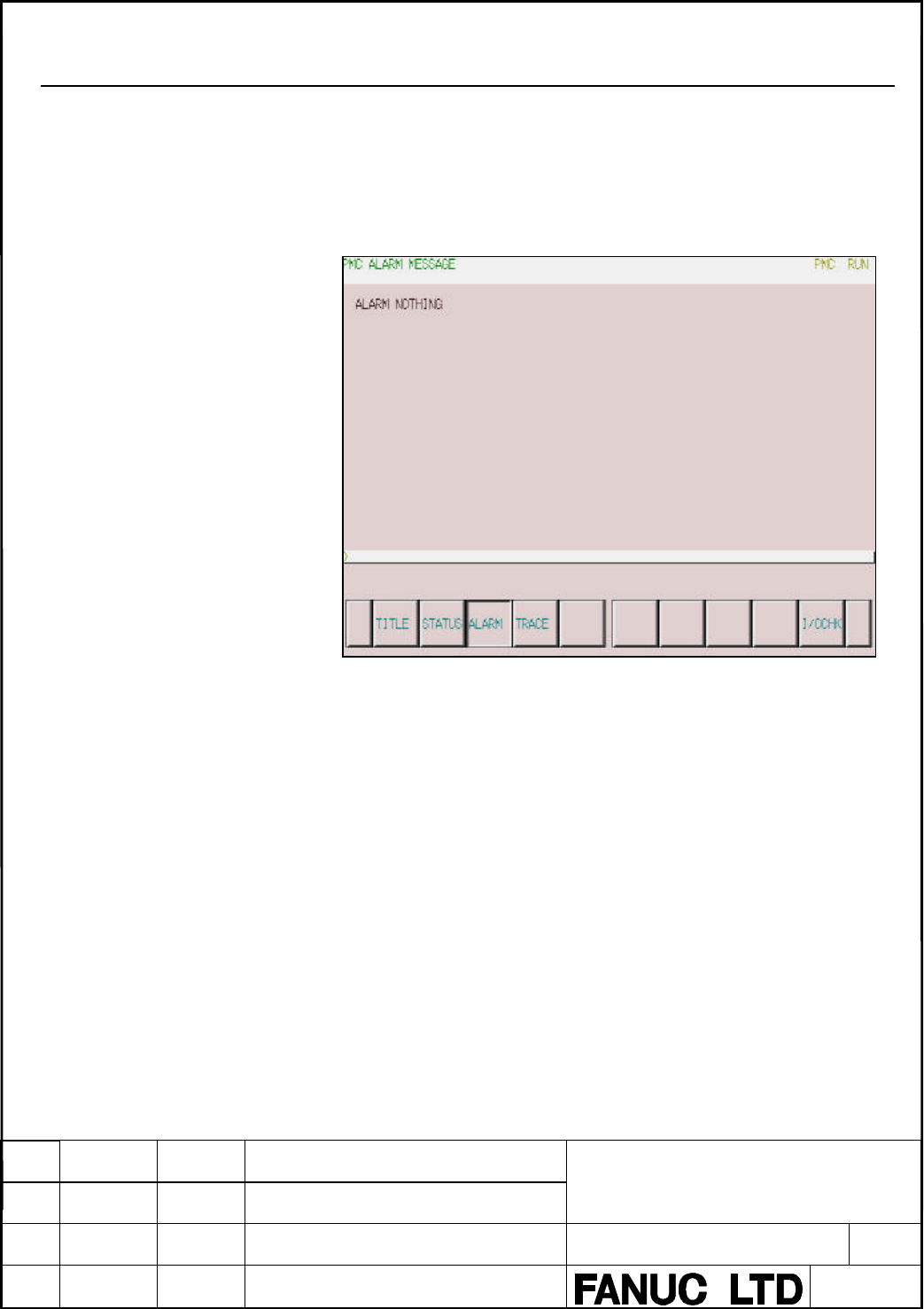
- Page 2375.3.3 Alarm Screen (ALARM) If an alarm condition occurs in the PMC, pressing the [PMC] soft key from the NC system displays the following alarm message instead of the PMC basic menu. The soft keys displayed on this screen remain the same as on the PMC basic module screen. In addition, character stri
- Page 2385.3.4 Trace screen (TRACE) 5.3.4.1 Overview On the trace screen, you can trace specified signals. The result of the trace is displayed as the time chart of signals. There are two tracing modes. One is the “Time Cycle” mode that samples the state of the signals at every specified cycle time. The othe
- Page 2395.3.4.2 Setting of Trace Parameter Pushing the [SETING] soft key displays the “Parameter Setting” screen. The following is the screen example of the trace execution by “TIME CYCLE” mode. “Parameter Setting” has two screens. The page number is displayed on up right of the screen. The page key changes
- Page 240The following is the screen example of the trace execution by “SIGNAL TRANSITION” mode. - SAMPLING MODE Determines the sampling mode. Select one by cursor key or soft key. Soft keys display when the cursor is put on “SAMPLING MODE”. Explanation: TIME CYCLE Samples at every specified cycle time. SIGN
- Page 241- SAMPLING TIME This parameter is displayed when “TIME CYCLE” is set on “SAMPLING MODE”. The execution time of trace is inputted. The value of “SAMPLING SESOLUTION” or the number of specified signal address changes the range of the value that is able to input. The range is displayed on the right of
- Page 242NOTE In the string of the symbol that can be displayed, there is a limitation of maximum 16 characters. The SYMBOL name is displayed only in case of the bit symbol. ADRESS Changes the symbol name display to the address display and changes the soft key to [SYMBOL]. - STOP CONDITION TRIGGER MODE When
- Page 243The graph is displayed on the right of the edit box. The edge of the left hand is as 0% and the edge of the right hand is as 100%. The position indicated by the input value is displayed as a gauge. - SAMPLING CONDITION When “SIGNAL TRANSITION” is set on “TRACE MODE”, this parameter is enabled. Selec
- Page 244“TRIGGER” is set on “SAMPLING CONDITION”, this parameter is enabled. Input trigger mode that determines the condition of specified trigger. Soft keys display when the cursor is put on “SAMPLING CONDITION TRIGGER MODE”. Explanation: RISE Samples the status of specified signals by rising up of the tri
- Page 245In case of inputting discrete bit addresses, any bit address can be inputted. Moreover, when you input byte address, all bits of the address (bit0-bit7) are set automatically. Maximum 32 points of signal address can be inputted. Increasing the number of the signal address changes the capacity of “SA
- Page 246- TRIGGER SETTING OF THE SAMPLING SIGNALS When “SIGNAL TRANSITION” is set on “TRACE MODE” and “ANY CHANGE” is set on “SAMPLING CONDITION”, the check boxes on the right of the sampling address or symbols are displayed as follows. Check the signals that should trigger the sampling in the setting signa
- Page 2475.3.4.3 Execution of Trace On trace screen, pushing [START] soft key starts the execution of trace after you set the trace parameter correctly. The following is the screen example of the trace execution by “TIME CYCLE” mode. The result of trace is immediately displayed during execution of the trace.
- Page 248The following is the screen example of the trace execution by “SIGNAL TRANSITION” mode. In “SIGNAL TRANSITION” mode, graphic display is not refreshed until any signal for sampling trigger changes. TITLE FANUC PMC-MODEL SD7 Programming Manual DRAW.NO. 01 01.11.26 Hanaoka New A-78550E EDIT DATE DESIG.
- Page 2495.3.4.4 Operation after Execution of Trace When the execution is finished, the result of trace is displayed. The following is the screen example of trace by “TIME CYCLE” mode. The cursor indicating current position is initially displayed on the original point (0 point). The position of the cursor is
- Page 250The following is the screen example of trace by “SIGNAL TRANSITION” mode. After the execution, following operation is enabled. (1) SCROLL OF SCREEN Using cursor up/down key and page up/down key enables the vertical scroll for the specified signal. Using cursor right/left key, [NEXT>>] soft key and [
- Page 251(2) AUTOMATIC CALCULATION OF THE SELECTED RANGE Pushing [MARK] soft key marks the current position and displays the mark cursor. If the mark cursor duplicates with the current position cursor, the current position cursor has priority of display. The “MARK POSITION” that shows the position of the mar
- Page 252(3) ZOOM IN/ZOOM OUT OF WAVEFORM Pushing [Z.IN] soft key magnifies the display of chart. Pushing [Z.OUT] soft key reduces the display of chart. Pushing these soft keys also change the scale value of the graduation on the graph. When trace is just finished, the default zooming level was the most magn
- Page 2535.3.5 Displaying and Setting The Configuration Status of I/O devices (I/OCHK) Call this screen by pressing of soft key [I/OCHK] in PMCDGN. There are following sub screens under the I/O Check screen. Soft keys are displayed when each function can be used. Please refer to the manual about requirement
- Page 2545.3.5.1 I/O Link Connecting Check Screen (IOLNK) The I/O Link connecting check screen displays the types and ID codes of the connected I/O devices for each group. If there is a problem of input or output signals for I/O devices, check connection of I/O Link by referring to this screen. Call this scr
- Page 255Table 5.3.5 Displayed type and true type of I/O Units Displayed I/O Unit ID True I/O Unit CONNECTION UNIT 80 Connection Unit OPERATOR PANEL 82 Connection Unit for Operators Panel I/O-B3 83 I/O B3 IO UNIT-MODEL B 84 I/O Unit-MODEL A 86 87 PLC SERIES 90-30 45 PLC SERIES 90-30 POWER MATE / IO LINK BETA
- Page 2565.4 Displaying and Setting the PMC Parameters (PMCPRM) 5.4.1 Overview Pressing the [PMCPRM] soft key causes the PMCPRM screen to appear. The PMC parameters in the permanent memory areas (%MK, %SK and % R) can be displayed and set using the CNC display. 5.4.2 Input PMC Parameters From MDI Panel Usual
- Page 257- If the sequence program can be stopped (STOP state), for example, while it is being debugged i) Stop the sequence program. ii) The parameter protection is released; so data can be entered for them. WARNING If a sequence program is stopped while the machine is operating, the machine may behave unex
- Page 2585.4.3 Setting and Display screen 5.4.3.1 Keep Relay (KEEPRL [%MK, %SK]) KEEPRL [%MK] The %MK Relays and the Data for controlling nonvolatile memory are set and displayed on this screen. TITLE FANUC PMC-MODEL SD7 Programming Manual DRAW.NO. 01 01.11.26 Hanaoka New A-78550E EDIT DATE DESIG. DESCRIPTIO
- Page 259KEEPRL [%SK] For %SK, the system area used by the management software is divided. Note Be careful of using the %SK Relays, because they are used by PMC Management Software. %SK is displayed by the setup of the GENERAL screen of PMC setting. Refer to 5.4.4.1 Screen for displaying General settings (GE
- Page 260%SK00003 0 : The sequence program is executed automatically when the power is turned on. #RUN_NAT 1 : The sequence program is executed when the [RUN] soft key is pressed. %SK00005 0 : Data cannot be entered at the FORCING screen. #EN_RAM 1 : Data can be entered at the FORCING screen. WARNING Set thi
- Page 2615.4.3.2 Data Register Table (DATA [%R]) DATA REGISTER TABLE consists of 2 screens, that is, Data Register Table Controlling Data screen and Data Register Table screen. (1) Data Register Table Controlling Data Screen Data Register Table Controlling Data Screen for controlling Data Register Table is d
- Page 262NOTE 0: Binary 1: BCD Table Parameter #7 #6 #5 #4 #3 #2 #1 #0 0: Available to input 1: Unavailable to input (Protection mode) 0: Binary of BCD (The bit 0 is valid 1: Hexadecimal (The bit 0 is invalid.) Data type TYPE DATA FORM LENGTH 0 BYTE 1 byte 1 INT, UINT, WORD 2 bytes 2 DINT, UDINT, DWORD 4 byt
- Page 263(2) Data Register Table Screen If the Data Register Table Controlling Data is set, Data Register Table Screen is displayed by pressing the soft key [G.DATA]. Group No. Page No. (Change pages with the page keys) The address used by sequence program Press this key after typing the address (ex. “%R8” %
- Page 2645.4.4 Setting screen (SETING) Pushing the [SETING] soft key on the PMC basic module screen displays the following setting menu screen. Contents of the menu. 1.GENERAL Screen for displaying general setting data. 2.EDIT/DEBUG Screen for displaying setting data related to editing and debugging. 3.ONLIN
- Page 2655.4.4.1 Screen for displaying General settings (GENERAL) Pushing the [GENERAL] soft key displays the following screen. (%SK54) (%SK15) (%SK5) (%SK8) (%SK23) (%SK24) (%SK1) (%SK3) (%SK19) (%SK2) - SIGNAL TRACE START (%SK54) MANUAL (0): Executes the tracing with [EXEC] softkey. AUTO (1): Starts the tr
- Page 266- DATA REGISTER TABLE CONTROL SCREEN (%SK8) YES (0): Displays PMC parameter data register table control screen. NO (1): Does not displays PMC parameter data register table control screen. - HIDE PMC PARAMETER (%SK23) NO (0): Allows PMC parameter display. YES (1): Prevents PMC parameter display. NOTE
- Page 267- PROGRAMMER ENABLE (%SK2) NO (0): Disables embedded programmer function. YES (1): Enables embedded programmer function. NOTE This setting effects some PMC functions. Please refer to "5.4.4.3 Programmer protection function" TITLE FANUC PMC-MODEL SD7 Programming Manual DRAW.NO. 01 01.11.26 Hanaoka Ne
- Page 2685.4.4.2 Screen for Displaying the Setting Data Related to Editing and Debugging (EDTDBG) (%SK17) (%SK49) - WRITE TO FROM (EDIT) (SK17) NO (0): The sequence program is not automatically written to F-ROM after reading in I/O screen. YES (1): The sequence program is automatically written to F-ROM after
- Page 2695.4.4.3 Programmer Protection Function CAUTION This section contains important information for developers of application system controlled by PMC. Improperly implemented application system may increase possibility of defects in its safety. Careful examinations and considerations on using and impleme
- Page 2705.4.4.3.1 PROGRAMMER ENABLE (%SK2) If you set ”PROGRAMMER ENABLE ” to ”YES”, it enables the following functions as a supervisor mode. - Start/stop of ladder - Forcing function - Override function *1 - I/O screen - Online setting screen - Setting screen for keep relay %SK NOTE 1 The override function
- Page 2715.4.4.3.3 EDIT ENABLE (%SK15) If you set ”EDIT ENABLE” to ”YES”, it enables the following functions which can edit the program. - Reading of sequence program on the I/O screen *1 - Setting screen for keep relay %SK NOTE 1 These screens with stop of ladder program require below setting ”ALLOW PMC STO
- Page 2725.4.4.3.5 RAM WRITE ENABLE (%SK5) If you set ”RAM WRITE ENABLE” to ”YES”, it enables both the forcing function and the override function. NOTE The override function also requires the setting of ”OVERRIDE ENABLE” in the setting parameters (EDIT/DEBUG). 5.4.4.3.6 DATA REGISTER TABLE CONTROL SCREEN (%S
- Page 2735.4.4.4 EXAMPLE FOR SETTING PARAMETERS 1) If you want to prohibit completely operator from accessing the sequence program; PROGRAMMER ENABLE (%SK2) ”NO” HIDE PMC PROGRAM (%SK1) ”YES” EDIT ENABLE (%SK15) ”NO” ALLOW PMC STOP (%SK19) ”NO” 2) If you want to allow operator only monitoring the sequence pr
- Page 2745) The case that operator who familiar with the machine and the ladder sequence operate all the PMC programmer functions; PROGRAMMER ENABLE (%SK2) ”YES” HIDE PMC PROGRAM (%SK1) ”NO” WARNING If a sequence program is stopped while the machine is operating, the machine may behave unexpectedly. Before s
- Page 2755.4.4.5 Screen for Setting/Displaying Online Monitor Parameters (ONLINE) If PROGRAMMER ENABLE is set to YES on the GENERAL screen, the [ONLINE] soft key appears on the setting menu screen. Pressing this soft key displays the following screen. When you use the online function, the setting of communic
- Page 276- CHANNEL A channel number to be used is displayed. The number can also be entered. - BAUD RATE 300: A baud rate of 300 is specified. 600: A baud rate of 600 is specified. 900: A baud rate of 900 is specified. 1200: A baud rate of 1200 is specified. 2400: A baud rate of 2400 is specified. 4800: A ba
- Page 277If the high speed interface is included in the system configuration, the HIGH SPEED I/F prompt menu appears above the RS-232C status display menu, and the HIGH SPEED I/F status display menu appears below the RS-232C status display menu. - HIGH SPEED I/F (prompt) USE: A HIGH SPEED I/F port can be con
- Page 2785.4.4.5.1 Setting of online connection To communicate with FAPT LADDER-IIIC, you need to put the PMC system in waiting situation of the connection. There are two ways for setting this, setting at PMC screen and setting in NC parameter. Also, there are three connection types, for example Ethernet or
- Page 279(b) Setting of online connection by NC parameter You can enable and disable the online connection for Ethernet and RS-232C by NC parameter No.24 without setting on the PMC online monitor setting screen. This NC parameter is made effective immediately after setting the parameter. If the value of this
- Page 2805.4.4.5.2 Setting of Ethernet parameters When you try to connect FAPT LADDER-IIIC with PMC by Ethernet, it is necessary to set some Ethernet parameters. The setting of Ethernet parameters can be set in the following Ethernet parameter screen of CNC. Please refer to “FANUC Ethernet Board/DATA SERVER
- Page 2815.4.4.5.3 Communication Status The communication status of RS-232C and HIGH SPEED I/F are displayed at the online monitor screen during the online communication. USE TIME : The maximum time in the communication processing is displayed. RS-232C : The communication condition of RS-232C is displayed. H
- Page 282The display messages and the meanings are shown in the table of below. Displayed messages Meanings INACTIVE The communication is inactive. The communication is being stopped. STOPPING (Wait for the termination of communication) The communication is being started. STARTING (Wait for the termination o
- Page 2835.5 Sequence Program Execution 5.5.1 Starting and Stopping a Sequence Program (1) Starting a sequence program (RUN) When a program is stopped, clicking the [RUN] soft key causes the program to start and the status line display to change to “PMC RUN.” The sequence program starts from the beginning. T
- Page 2845.5.2 Forced Termination of Sequence Program To forcibly stop starting the sequence program at power-on, turn on the power by pressing the [Z] key while pressing the [CAN] key. This method is effective for locating the error when a system error occurs after power is turned on and when the error may
- Page 2855.6 Writing, Reading, and Verifying the Sequence Program and PMC Parameter Data (I/O) 5.6.1 I/O Screen When the [I/O] soft key on the PMC main menu is pressed, the following screen appears. On this screen, sequence programs and PMC parameters can be written to the specified device, read from the dev
- Page 286When you read a file from an I/O device, one of following messages appear and whether to operate the important thing is confirmed.
READING SEQUENCE PROGRAM OR PMC PARAMETER REQUIRES SPECIAL CARE. * READING IMPROPER DATA MAY CAUSE UNEXPECTED MOVEMENT OF MACHINE. * PROGRAM WILL BE STOPPED BY - Page 287In STATUS in the lower part of the screen, a detailed explanation of execution and the execution status are displayed. During write, read, and comparison, the size of the data already transferred is indicated as the execution (intermediate) result. The following gives a display example shown when PM
- Page 2885.6.2 Outputting to and Inputting from Memory Cards When “MEMORY CARD” is selected for DEVICE, output to and input from memory cards are enabled. - FUNCTION A data I/O command appears. Select FUNCTION with the item select cursor, then select an item by moving the content select soft key horizontally
- Page 289
READING SEQUENCE PROGRAM OR PMC PARAMETER REQUIRES SPECIAL CARE. * READING IMPROPER DATA MAY CAUSE UNEXPECTED MOVEMENT OF MACHINE. * PROGRAM WILL BE STOPPED BY READING SEQUENCE PROGRAM. ARE YOU SURE YOU WANT TO READ THIS FILE? When you proceed to read PMC parameters, new PMC parameters wil - Page 290Explanation of options PROGRAM: Outputs sequence programs only. PARAMETER: Outputs PMC parameters. - FILE NO. FILE NO. is displayed only when “READ,” ”COMPARE,” or “DELETE” is selected for “FUNCTION.” Enter the file number in the edit box. - FILE NAME FILE NAME is displayed when “WRITE,” “READ,” “CO
- Page 291Flash Memory Card SRAM Card Supported Unsupported ATA Card Card Card Read of a file O O O O Format of a card O O X O Write of a file O O X O Delete of a file O X X O List of a file O O O O TITLE FANUC PMC-MODEL SD7 Programming Manual DRAW.NO. 01 01.11.26 Hanaoka New A-78550E EDIT DATE DESIG. DESCRIP
- Page 2925.6.3 Memory Card List Screen When MEMORY CARD is selected in DEVICE, pressing the [LIST] soft key displays the following screen: If a memory card holding files is in the slot, the contents of the memory card are displayed as shown in the above. NOTE Up to 128 files can be displayed on this screen.
- Page 293To return the screen display to the previous screen without selecting a file, press the return key. When the memory card is replaced with another card while the list screen is being displayed, the displayed information is not updated automatically. In this case, press the [REFRES] soft key. The cont
- Page 2945.6.4 Outputting to and Inputting from Flash ROM When “FLASH ROM” is selected for DEVICE, output to and input from flash ROM are enabled. - FUNCTION The available data input/output commands are displayed. Select the desired command by moving the cursor horizontally to that command or select it with
- Page 2955.6.5 Outputting to and Inputting from Floppy When “FLOPPY” is selected for “DEVICE”, output to and input from a floppy cassette or a handy file that is connected via RS-232C are enabled. - FUNCTION The available data input/output commands are displayed. Select the desired command by moving the curs
- Page 296When you read a file from a floppy cassete or a handy file, one of following messages appear and whether to operate the important thing is confirmed.
READING SEQUENCE PROGRAM OR PMC PARAMETER REQUIRES SPECIAL CARE. * READING IMPROPER DATA MAY CAUSE UNEXPECTED MOVEMENT OF MACHINE. * PROGRAM - Page 297“KIND OF DATA” Explanation of options PROGRAM: Outputs sequence program. PARAMETER: Outputs PMC parameters. - FILE NO. “FILE NO.” is displayed only when “READ”, “COMPARE”, or “DELETE” is selected for “FUNCTION”. Enter the file number in the edit box. - FILE NANE “FILE NAME” is displayed when “WRITE”
- Page 298Explanation of soft keys [EXEC]: Executes the function selected for “FUNCTION”. During execution, the soft key disappears and the [CANCEL] soft key appears to the right of the key. [CANCEL]: Cancels the execution of the function. When the function terminates normally, the soft key disappears. [LIST]
- Page 2995.6.6 Floppy List Screen When “FLOPPY” is selected for “DEVICE”, pressing the [LIST] soft key display the following screen. The contents of the floppy cassettes or the handy files are displayed. When a file is selected on this screen, the screen display can be returned to the previous screen. To sel
- Page 300Explanation of soft keys [SELECT] Selects a file, and returns the screen display to the previous screen. [REFRES] Redisplays the contents of a floppy cassette or a handy file. TITLE FANUC PMC-MODEL SD7 Programming Manual DRAW.NO. 01 01.11.26 Hanaoka New A-78550E EDIT DATE DESIG. DESCRIPTION 299/316�
- Page 3015.6.7 Outputting to and Inputting from Other Input/Output Devices When “OTHERS” is selected for “DEVICE”, output to and input from other input/output devices are enabled. - FUNCTION The available data input/output commands are displayed. Select the desired command by moving the cursor horizontally t
- Page 302
READING SEQUENCE PROGRAM OR PMC PARAMETER REQUIRES SPECIAL CARE. * READING IMPROPER DATA MAY CAUSE UNEXPECTED MOVEMENT OF MACHINE. * PROGRAM WILL BE STOPPED BY READING SEQUENCE PROGRAM. ARE YOU SURE YOU WANT TO READ THIS FILE? When you proceed to read PMC parameters, new PMC parameters wil - Page 303Soft keys displayed when the question selection cursor is positioned to “KIND OF DATA” Explanation of options PROGRAM: Outputs sequence program. PARAMETER: Outputs PMC parameters. Explanation of soft keys [EXEC]: Executes the function selected for “FUNCTION”. During execution, the soft key disappear
- Page 3045.6.8 Port Setting Screen When “FLOPPY” or “OTHERS” is selected for “DEVICE”, the [PORT] soft key is displayed. When the key is pressed, the following screen appears. The following gives a display example shown when “OTHERS” is selected for “DEVICE”. This screen allows the setting of the communicati
- Page 305- BAUDRATE 1200: Sets the baud rate to “1200”. 2400: Sets the baud rate to “2400”. 4800: Sets the baud rate to “4800”. 9600: Sets the baud rate to “9600”. 19200: Sets the baud rate to “19200”. - STOP BIT 1 BIT: Sets the number of stop bits to “1”. 2 BIT: Sets the number of stop bits to “2”. - WRITE
- Page 3065.6.9 I/O Screen Error Messages The error messages that may appear on the I/O screen and their meanings and actions are listed below. - Error messages displayed during memory card I/O operation Displayed error message Meaning and action MEMORY CARD IS NOT READY No memory card is installed. Action: C
- Page 307FILE NUMBER CAN NOT SELECTED The file number cannot be selected. Action: If the file does not exist, the key entry is invalid. If this error occurs even when the cursor is placed at a file name, contact the FANUC service center. INPUT FILE NUMBER IS NOT EXIST The entered file number is not present.
- Page 308I/O DEVICE IS NOT ATTACHED OR IN Any I/O device is not connected, or some errors have ERROR STATUS occurred in it. Action: Check the power of I/O device is ON. Check the I/O device is connected. Check the cable that connects I/O device with PMC is correct one. If some error has occurred in I/O devic
- Page 309APPENDIX A Differences Between PMC-SB7 This chapter explains those functions that are supported for the PMC-SB7 but not for the PMC-SD7, as well as those functions which are supported but with limitations. A.1 FANUC I/O Link The following functions are not supported. - Selectable I/O Link Assignment
- Page 310A.4 SYMBOL Key Input The limitation to input SYMBOL name is as the following. - The small letter cannot be inputted. Input the capital. - The '_' can not be input by key input. Input the '-'. - The '$' can not be input by key input. Input the '&'. A.5 PMCPRM The following functions are not supported
- Page 311A.7 Internal Editing The internal editing function is not supported. Program editing is performed using the programmer on the PC. To delete PMC data (sequence programs, PMC parameters), hold down the following keys and turn on the system power. Delete of sequence program:
+ Delete of all PMC - Page 312A.12 C Language function C Language function is not supported. A.13 Loader control function Loader control function is not supported. A.14 PROFIBUS Board PROFIBUS board is not supported. A.15 DeviceNet Board DeviceNet board is not supported. A.16 I/O Link-II Board I/O Link-II board is not supported.
- Page 313B ALARM MESSAGE LIST B.1 PMC ALARMS/SYSTEM ALARMS Alarm number Faulty location/corrective action Contents ER01 PROGRAM DATA ERROR 1) Re-input the sequence program. The sequence program is invalid. 2) Replace the master printed circuit board. ER02 PROGRAM SIZE OVER 1) Reduce the sequence program. The
- Page 314ER12 OPTION AREA Contact FANUC to reconfigure the The PMC management software is invalid. ERROR(xxxx) PMC management software. (The series of BASIC and OPTION do not match.) ER13 OPTION AREA Contact FANUC to reconfigure the The PMC C board management software is ERROR(xxxx) PMC management software.
- Page 315ER35 TOO MUCH OUTPUT DATA Reduce the amount of output data in The amount of output data in I/O Link group IN GROUP (xx) group xx. xx exceeds the limit (33 bytes). The excess data is nullified. ER36 TOO MUCH INPUT DATA IN Reduce the amount of input data in The amount of input data in I/O Link group G
- Page 316B.2 PMC system alarm messages Alarm number Faulty location/corrective action Contents PC004 CPU ERR xxxxxxxx:yyyyyyyy 1) Replace the master printed A CPU error occurred in the PMC. PC006 CPU ERR xxxxxxxx:yyyyyyyy circuit board. xxxxxxxx and yyyyyyyyy are internal error PC009 CPU ERR xxxxxxxx:yyyyyyy
- Page 317PC090 NMI(___) xxxxxxxx:yyyyyyyy 1) Replace the master printed An NMI with an unknown cause occurred in circuit board. the PMC management software. 2) If the error recurs even after the replacement, contact FANUC to report the status (displayed message, system configuration, operation, when the erro