Series 30i-MODEL A, Tool axis direction tool length compensation Additional Manual Page 13
Additional Manual
A-79381E
Title
Draw
No.
11/23
page
FANUC Series 30i-MODEL A
Tool Axis Direction Tool Length
Compensation
Ed. Date Design Description
Date
Jan.16.’04 Design. Apprv.
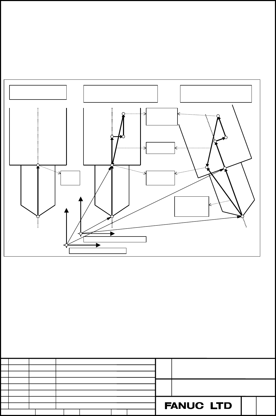
Shifting the control point
Conventionally, the center of a rotation axis was used as the control point.
The control point can now be shifted as shown in the figure below.
Then, when the rotation axis is at the 0-degree position also in tool length
compensation along the tool axis (G43.1), the control point can be set to the
same position as that for ordinary tool length compensation (G43).
The control point here is indicated with machine coordinates.
When linear interpolation is specified, for example, this control point moves
linearly.
Shift
vector
Ordinary tool length
compensation
(
G43
)
Tool lenght compensation along
tool axis (G43.1):
Whin tool is not tilted
Control
point
Control
point before
shift
Control
point
Tool length compensation along
tool axis (G43.1) :
When tool is tilted
Machine coordinate ori
g
in
Work
p
iece coordinate ori
g
in
Tool length
compensation
vector
Fig. 1.2. (c) Shift of the Control Point
Contents Summary of Series 30i-MODEL A, Tool axis direction tool length compensation Additional Manual
- Page 1TECHNICAL REPORT NO. TMN 04/020E Date :Mar .30, 2004 General Manager of Software Laboratory FANUC Series 30i-A Newly additional functions 1. Communicate this report to: Your information only GE Fanuc-N, GE Fanuc-E FANUC Robotics MILACRON Machine tool builder Sales agency End user 2. Summary for Sale
- Page 2FANUC Series30i –A newly additional functions Drawing number Functions 1 A-79227E External Data Input 2 A-79226E One Touch Macro call 3 A-79196E Temporary absolute coordinate setting 4 A-79354E System alarm 5 A-79349E Touch Panel Control 6 A-79253E Distance coded linear scale interface 7 A-79364E Li
- Page 3FANUC Series 30i-MODEL A Tool axis direction tool length compensation Specifications FANUC Series 30i-MODEL A Title Tool Axis Direction Tool Length Compensation Draw A-79381E No. Ed. Date Design Description page 1/23 Date Jan.16.’04 Design. Apprv.
- Page 41.1 Tool Axis Direction Tool Length Compensation General When a five-axis machine that has two axes for rotating the tool is used,tool length compensation can be performed in a specified tool axis direction on a rotation axis. When a rotation axis is specified in tool axis direction tool length comp
- Page 5Explanation - Command for tool axis direction tool length compensation The tool compensation vector changes as the offset value changes or movement is made on a rotation axis. When the tool compensation vector changes, movement is made according to the change value along the X-axis, Y-axis, and Z-ax
- Page 6(2) B-axis and C-axis, with the tool axis on the Z-axis B C Z Workpiece C B Y X Vx = Lc * sin(b) * cos(c) Vy = Lc * sin(b) * sin(c) Vz = Lc * cos(b) (3) A-axis and B-axis, with the tool axis on the X-axis A B Z A Workpiece X B Y Vx = Lc * cos(b) Vy = Lc * sin(b) * sin(a) Vz = -Lc * sin(b) * cos(a) F
- Page 7(4) A-axis and B-axis, with the tool axis on the Z-axis, and the B-axis used as the master B A Z B X Workpiece Y A Vx = Lc * cos(a) * sin(b) Vy = -Lc * sin(a) Vz = Lc * cos(a) * cos(b) (5) A-axis and B-axis, with the tool axis on the Z-axis, and the A-axis used as the master A B Z Y B Workpiece X A
- Page 8- Tool holder offset The machine-specific length from the rotation center of the tool rotation axes (A- and B-axes, A- and C-axes, and B- and C-axes) to the tool mounting position is referred to as the tool holder offset. Unlike a tool length offset value, a tool holder offset value is set in parame
- Page 9- Rotation axis offset Set offsets relative to the rotation angles of the rotation axes in parameter No. 19659. The compensation vector calculation formula is the same as that used for rotation axis origin compensation, except that Bp and Cp are changed to rotation axis offsets. When rotation axis o
- Page 101.2 Control Point Compensation of Tool Length Compensation Along Tool Axis Normally, the control point of tool length compensation along the tool axis is the point of intersection of the centers of two rotation axes. The machine coordinates also indicate this control point. This section explains the
- Page 11According to the machine type, set the values listed in the followingtable: Table 1 (a) Setting the Tool Holder Offset and Rotation Center Compensation Vector Tool holder offset Rotation center Machine type Parameter No. 19666 compensation vector Parameter No. 19661 (1) A- and C- axes. Tool Length f
- Page 12- Spindle center compensation Compensation of the spindle center is performed. The amount of spindle center compensation is set in parameter No. 19662. Since parameter No. 19662 is an axis type parameter, the compensation amount for three axes (X, Y, and Z) can be set in this parameter. Second rotat
- Page 13Shifting the control point Conventionally, the center of a rotation axis was used as the control point. The control point can now be shifted as shown in the figure below. Then, when the rotation axis is at the 0-degree position also in tool length compensation along the tool axis (G43.1), the contro
- Page 14The method of shifting the control point can be selected using the following parameters: Table 1.2 (b) Methods of Shifting the Control Point SVC (bit 5 of SPR (bit 4 of parameter parameter Shift of controlled point No. 19665) No. 19665) 0 - Shift is not performed an not done conventionally 1 0 The c
- Page 15The shift vector (Sx, Sy, Sz) is calculated as follows: (A) When bit 5 (SVC) of parameter No. 19665 = 0, the vector is set to 0. (B) When bit 5 (SVC) of parameter No. 19665 = 1, and bit 4 (SBP) of parameter No. 19665 = 0: When the machine type is other than (3) Sx Cx + Jx Sy = − Cy + J
- Page 16Limitation - Automatic reference position return command (G28, G29, G30) Never specify an automatic reference position return command (G28, G29, or G30) in tool axis direction tool length compensation mode. If an automatic reference position return command is specified in tool axis direction tool le
- Page 17Parameters #7 #6 #5 #4 #3 #2 #1 #0 19650 RAP RAM [Input type] Parameter input [Data type] Bitaxis #0 RAM Specifies whether to use the axis as the rotation axis for tool axis direction tool length compensation. 0: Not used as the rotation axis. 1: Used as the rotation axis. Select two axes from among
- Page 18#1 RAP Specifies whether the rotation axis used for tool axis direction tool length compensation is an ordinary rotation axis. 0: Ordinary rotation axis. 1: Parameter axis. If this bit is set to 0, absolute coordinates are used as the coordinates of rotation axes in tool axis direction tool length c
- Page 1919655 Axis number of the linear axis to which a rotation axis belongs [Input type] Parameter input [Data type] Integeraxis [Valid data range] 0 - Max axes This parapeter is used for tool axis direction tool length compensation. When a rotation axis turns about a linear axis , the linear axis is refe
- Page 2019657 Master rotation axis number [Input type] Parameter input [Data type] Integerpath [Valid data range] 0 - Max axes When a machine does not have the rotation axis that turns about the tool axis, the axis number of a rotation axis used as the master axis is set. For machines not using the master-a
- Page 21Example for setting parameters that determine the machine configuration Tool axis derection: Z-axis Axis configuration: W, X,Y,Z,A,B Rotation axes: A-axis (axis rotating amout the X-axis), B-axis (axis rotating about the Y-axis) Master axis: A-axis Data No. Data 19655 W X Y Z A B 0 0 0 0 2 3 19656 3
- Page 2219660 Origin offset value of a rotation axis [Input type] Parameter input [Data type] Realaxis [Unit of data] degree [Minimum unit of data]Depend on the increment system of the applied axis [Valid data range] 9 digit of minimum unit of data (refer to standard parameter setting table(A)) (When the in
- Page 23#7 #6 #5 #4 #3 #2 #1 #0 19665 SVC SPR [Input type] Parameter input [Data type] Bitpath #4 SPR The controlled point is shifted by: 0: Automatic calculation. 1: Using parameter No. 19667. SVC (bit 5 of SPR (bit 4 of parameter parameter Shift of controlled point No. 19665) No. 19665 0 - Shift is not pe
- Page 24#5 SVC The controlled point is: 0: Not shifted. 1: shifted. NOTE When the machine has no rotation axis for rotating the tool (when parameter No. 19680 is set to 12 to specify the table rotation type), the controlled point is not shifted regardless of the setting of this parameter. 19666 Tool holder
- Page 2519667 Controlled-point shift vector [Input type] Parameter input [Data type] Realaxis [Unit of data] mm, inch (machine unit) [Minimum unit of data]Depend on the increment system of the applied axis [Valid data range] 9 digit of minimum unit of data (refer to standard parameter setting table(A)) (Whe