FANUC Series 16i/18i Additional Manual Page 12
Additional Manual
12
Edit
Apprv.
Apprv.Apprv.
Apprv.Desig.
Desig.Desig.
Desig.
Sheet
Title
Draw
No.
/
14
Date
DateDate
Date
Design
DesignDesign
Design
Descri
p
tion
Descri
p
tionDescri
p
tion
Descri
p
tion
Date
DateDate
Date
FANUC Series16i /18i – MB/TB
Retract for high-speed remote buffer
A
-78086EN/03
2000.03.15
02 2005.02.22 Out of frame 2 is added
03 2005.11.04 Out of frame 3 is corrected
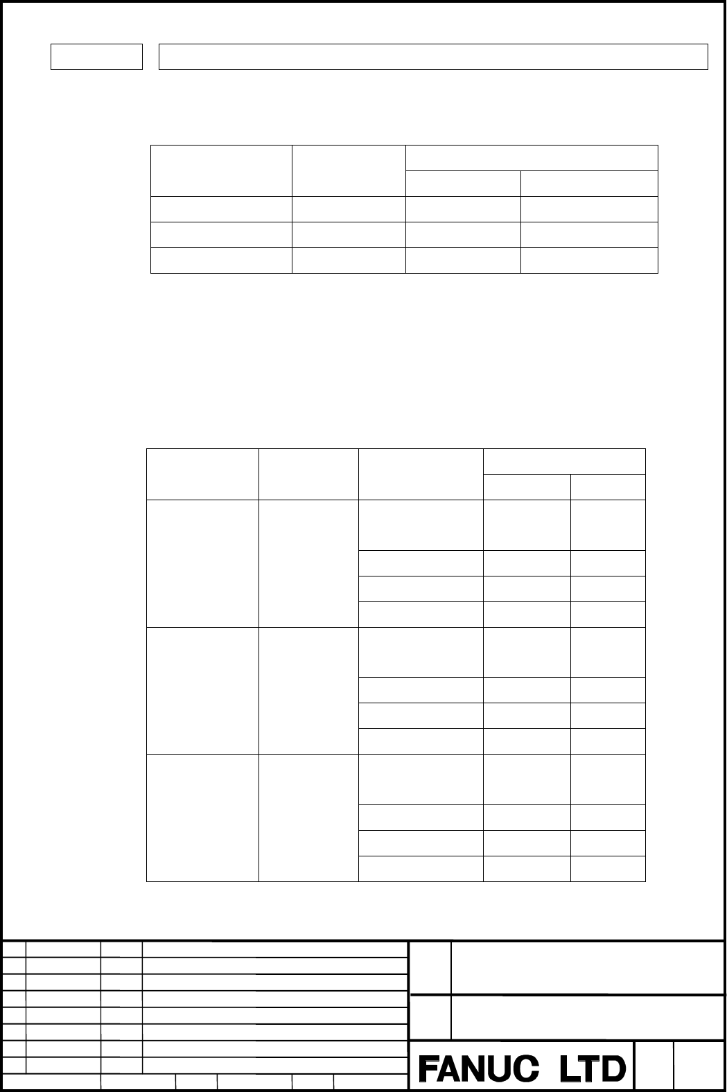
Number
7523 Feedrate for retract
[ Data type ] 2-word axis
[ Unit of data ]
[ Valid data range ]
Range of data
Increment unit Unit of data
IS-A,IS-B IS-C
Millimeter machine 1 mm/min 30 - 240000 30 - 100000
Inch machine 0.1 inch/min 30 - 96000 30 - 48000
Rotation Axis 1 deg/min 30 - 240000 30 - 100000
At the retract operation of the high-speed remote buffer, the feedrate for retract of
each axis is set.
(Note 1)
At the total feedrate of the high-speed remote buffer operation and this
parameter, the total feedrate is limited by the interpolation time. When
maximum speed of the table below is exceeded, P/S alarm 179 occurs.
Maximum feedrate
Increment unit Unit of data Interpolation time
IS-A, IS-B IS-C
16msec,8msec,
4msec
490000 49000
2msec 980000 98000
1msec 1960000 196000
Millimeter
machine
1 mm/min
0.5msec 3920000 392000
16msec,8msec,
4msec
190000 19000
2msec 380000 38000
1msec 760000 76000
Inch machine 0.1 inch/min
0.5msec 1530000 153000
16msec,8msec,
4msec
490000 49000
2msec 980000 98000
1msec 1960000 196000
Rotation Axis 1 deg/min
0.5msec 3920000 392000
Contents Summary of FANUC Series 16i/18i Additional Manual
- Page 1FANUC Series 16i /18i – MB/TB Specification Retract for High speed Remote buffer Contents 1. Outline .............................................................................................................................................................2 2. Specification .......................
- Page 21. Outline By this function, even if a machine goes wrong suddenly, the machining process can be stopped safety while operating the high-speed remote buffer. The retract operation is done to each axis when the retract signal is input while operating the high-speed remote buffer, and the high-speed r
- Page 32. Specification The retract operation is done to each axis when the retract signal is input while operating the high-speed remote buffer, and the high-speed remote buffer operating does the deceleration stop. It enters the state of reset after retraction. The acceleration/deceleration type of the r
- Page 4When there is a standard axis, which passes a constant position at the cycle operation, the deceleration can be started at the specified timing. By setting the parameter of the standard axis (No.7524) and the absolute coordinate position (No.7525), the deceleration is started after the retract signa
- Page 5(Retract value <> 0) Specified position Specified position Deceleration starts Retract movement starts Feedrate value Retract value Time constant Time constant Time constant Retract signal ON (Retract value =0) Specified position Specified position Deceleration starts Feedrate value Time constant Re
- Page 6(Example of grinding oval cam) 1. C axis = 0 deg X axis X axis C axis 2. C axis = 90 deg X axis C axis C axis 3. C axis = 180 deg 360 X axis 0 C axis 1. 2. 3. 4. 1. 4. C axis = 270 deg X axis C axis Parameter No.7524 =3 (C axis) …………… standard axis No.7525 =0 (deg) …...……… Absolute coordinate positi
- Page 7It is possible to decelerate and stop the remote buffer operation at finishing the retract value 2 movement after inputting the retract signal. When the parameter No.7502#6 is set to 1 and the standard axis for retract is set to the 3 parameter No.7524, the remote buffer operation is decelerated and
- Page 8• The axis except the standard axis behavior (In case that the retract value do not remain.) 2 Deceleration starts Retract movement starts Feedrate value Time constant Time constant Time constant Retract signal ON • In case that the retract value is 0 Deceleration starts Feedrate value Time constant
- Page 93. Notes 1) The value of the deceleration movement is made based on the feedrate and the time constant at the beginning of the deceleration. Moreover, this value of the movement is not included in the value of retract. 2) Even if the high-speed remote buffer is operated, the input of the retract sig
- Page 104. Parameters Number #7 #6 #5 #4 #3 #2 #1 #0 7503 RNRST [ Data type ] Bit RNRST In the state of reset after retraction with operating the high-speed remote buffer, the reset signal RST(F0001.1) is: 0 : Output. 1 : Not output. Number #7 #6 #5 #4 #3 #2 #1 #0 3 7502 RBDEC [ Data type ] Bit 2 RBDEC At t
- Page 11(Note 1) The setting value is changed according to the interpolation time of the data of the high-speed remote buffer. In case of the interpolation time is 8msec : The time constant becomes a multiple of eight. In case of the interpolation time is 4msec : The time constant becomes a multiple of four
- Page 12Number 7523 Feedrate for retract [ Data type ] 2-word axis [ Unit of data ] [ Valid data range ] Range of data Increment unit Unit of data IS-A,IS-B IS-C Millimeter machine 1 mm/min 30 - 240000 30 - 100000 Inch machine 0.1 inch/min 30 - 96000 30 - 48000 Rotation Axis 1 deg/min 30 - 240000 30 - 10000
- Page 13Number 7524 Standard axis for retract [ Data type ] byte [ Valid data range ] 0 to 6 At the retract operation of the high-speed remote buffer, when there is a standard axis, which passes a constant position at the cycle operation, the deceleration can be started at the specified timing. By setting t
- Page 145. Signal #7 #6 #5 #4 #3 #2 #1 #0 G0065 HSRT [ Classification ] Input signal HSRT In high-speed remote buffering and high-speed cycle machining, 0: The retract operation is not done. 1: The retract operation is done. Title FANUC Series16i /18i – MB/TB Retract for high-speed remote buffer Draw No. A-