FS 16i/18i/21i-TA/MA, Fanuc Servo Motor ALPHA Series I/O Link Option Manual Handle Interface (Peripheral Equipment Control Interface) Additional Manual Page 3
Additional Manual
Edit
A-63648E
FANUC Series 16
i
/18
i
/21
i
- MA/TA
FANUC SERVO MOTOR ââ Series
Manual handle interface
2/ 6
Title
Drawing No.
Page
Data Signature Descriptio
2000/10/11
1. Specifications
1.1. Outline
By using this function, manual handle feed for â servo unit, by manual pulse generator
on the host (CNC), is available. Pulses from manual pulse generator are transferred from
the host (CNC) to the â servo unit , through I/O Link. Still further, by changing
parameter, the magnification of pulse can be changed. This function is available on the
peripheral control interface. This function is the optional function.
1.2. Detailed specifications
After the manual handle mode of â servo unit (MD1(Y0#0)=0, MD2(Y0#1)=0,
MD4(Y0#2) =1) is selected, the host informs the magnification of the manual handle
generator (MP1(Y7#4),MP2(Y7#5)) and changes the manual pulse counter.
â servo unit operates the motor by reading the varied amount of the manual pulse
counter.
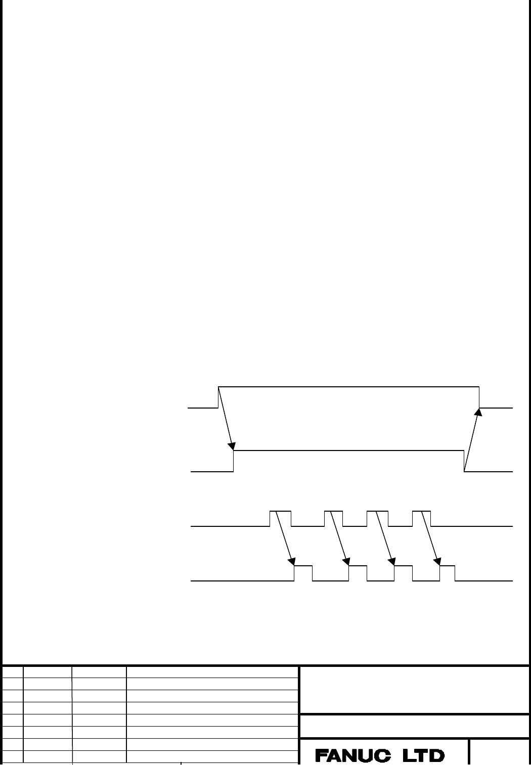
[ Time chart ]:
H: The management of the host.
â: The management of the â servo unit.
H: Manual handle mode
MD1/2=0
MD4=1
H: Magnification of
manual handle
(MP1/2)
Manual pulse counter
â: Motor driving
Contents Summary of FS 16i/18i/21i-TA/MA, Fanuc Servo Motor ALPHA Series I/O Link Option Manual Handle Interface (Peripheral Equipment Control Interface) Additional Manual
- Page 1TECHNICAL REPORT (MANUAL) TMN00/0157 Date: November 7, 2000 General Manager of Software Laboratory FANUC Series 16i /18i /21i –TA/MA FANUC SERVO MOTOR âSeries I/O Link Option Manual handle interface ( Peripheral equipment control interface) 1. Communicate this report to: Your information GE Fanuc-N,
- Page 2FANUC Series 16i/18i/21i - MA/TA FANUC SERVO MOTOR âSeries I/O Link Option Manual handle interface ( Peripheral equipment control interface) Specifications 1. SPECIFICATIONS . . . . . . . . . . . . . . . . . . . . . . . . . . . . . . . . . . . . . . . . . . . . . . . . . . . . . . . . . . . . . . .
- Page 31.Specifications 1.1.Outline By using this function, manual handle feed for âservo unit, by manual pulse generator on the host (CNC), is available. Pulses from manual pulse generator are transferred from the host (CNC) to the â servo unit , through I/O Link. Still further, by changing parameter, the
- Page 42.Parameters 2.1.Parameter for âservo unit No. #7 #6 #5 #4 #3 #2 #1 #0 005 MP IOH [Data type] Bit IOH Manual handle feed by way of I/O Link is: 0: Unavailable. 1: Available. [Caution] When ‘IOH’ is set to 1, please never forget to set the parameter No3#6(EXPLS), for âservo unit , to 0. M P On the ma
- Page 53.Signals 3.1.Signals for âservo unit Signal address No. #7 #6 #5 #4 #3 #2 #1 #0 Yy+0 MD4 MD2 MD1 Yy+7 MP2 MP1 Mode selection signal MD1, MD2, MD4 [Classification] CNC(host) Servo unit [Function] This signal selects the operation mode of the âservo unit. [Operation] By using this signal, the operati
- Page 6[Caution] 1. These signals are available when the Parameter No.5#5(MP) is set to 1. 2. These signals are available on the manual handle mode only. 3. These signals are shared with the signals for rapid traverse override. On manual handle mode, these signals mean the Incremental Feed signals. On othe
- Page 74.Applicable series 4.1.Applicable CNC control software ( FS16i /18i /21i ) Series Version B0F1 15 or later FANUC Series 16i-MA B1F1 14 or later FANUC Series 16i-TA BDF1 15 or later FANUC Series 18i-MA BEF1 14 or later FANUC Series 18i-TA DDF1 11 or later FANUC Series 21i-MA BEF1 11 or later FANUC S