Built-In AC Spindle Motors Alpha iB Series Descriptions Page 35
Descriptions
B-65292EN/03 SPECIFICATIONS 1.SPECIFICATIONS
- 19 -
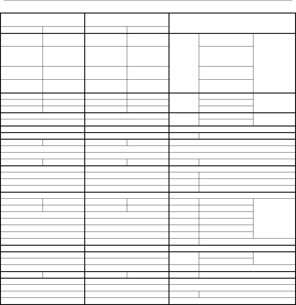
α132L/25000iB α160M/20000iB
Model name
1705-B140#Y617 1723-B140#Y627
Type No.(A06B-) *8
Low High Low High Item
15 18.5 11 18.5 S1 continuous
(103) (92) (62) (105) (Max. current)
18.5 22 15 22 S2 SHORT TIME
30min. 15min. 15min. 30min. Rated minutes *1
(118) (111) (73) (121) kW (Max. current) Rated output
15 (A) S3 40%
(87) (Max. current)
15 S3 25%
(108) (Max. current)
1000 6000 850 4200 Base *2
2000 20000 3000 20000 min
-
1
Power constant Rated speed
2000 25000 3000 20000 Maximum
143 124 Nm S1 continuous Rated
177 239 S2 or S3 Max. torque
0.82 Power factor
132-194 V
A
C
Rated voltage of motor input *3
Y
∆
Y
∆
Winding connection
Connection F <1>-<4> Connection F <1>-<4> Power leads connection *5
4 4 Number of poles
114 10 166 14
mΩ ±5%
Resistance of winding *10
H H Insulation class
≤
125
≤
125
K Temperature rise of winding
3 3 mm Required clearance
155 180
±5°C
Overheating temperature setting
IC9U7A7 IC9U7A7 IC code
20 20 20 20
°C
Temperature
≤
14
≤
14
≤7 ≤18
K Temperature rise
≥
13.5
≥
13.5
Liter/min Flowing rate Coolant
1.87 1.87
J/g⋅K
Specific heat
0.78 0.78
g/cm
3
Density
≤
2940
≤
2940
kPa Pressure *11
≥
5200
≥
5800
W Capacity of cooler *12
T411 T411 BZi sensor *4
42 37 kg Stator Weight
13 15 Rotor
0.037 0.068
kgm
2
Rotor inertia
22.2 26.4 18 26.4 kW Allowable overload *6
30i 30i Spindle amplifier module (SPM-)
- - AC reactor (A81L-0001-) *13
18.5/29 18.5/29 kW Date for choice of PSM *7
Parameter spec. (A06B-6111-) *9
*1 Data indicate the output of constant power range.
*2 This speed is applied for S1 continuous rated. Refer to 2. POWER CURVES for details.
*3 This is not an input voltage of amplifier. This indicates that the input voltage of motor is changed when the motor output changes
within the rated output and speed.
*4 A860-2120-Txxx. For velocity and position feedback. Install to a rotating axis. Refer to 3.3 SENSOR.
*5 Refer to 2.3 POWER LEADS CONNECTION in the Part II.
*6 Reference data, applied for 1 minute. This value is not guaranteed.
*7 Reference data of Continuous/Maximum(at acceleration) output for the choice of PSM.
*8 The number indicates the type number of the standard model. For other specification numbers such as of a model with a different
sensor, refer to E. SPECIFICATION NUMBER in APPENDIX.
*9 Refer to the manual, the latest edition of Parameter Manual (B-65280EN) for details.
*10 The resistance of winding indicates reference data between the amplifier (SPM) and motor after motor power leads connection (the
actual resistance differs slightly depending on the length of the used power cable). To measure the resistance of winding, refer to 2.2
CHECKING THE WINDING RESISTANCE in II. INSTRUCTION before connection.
*11 Adjust the coolant pressure according to the O-ring you use.
*12 Actual calorie which must be removed from the motor is calculated as follows.
Q(W)=Flowing rate(l/min)×Specific heat(J/gK)×Density(g/cm
3
)×Temperature rise(K)×1000÷60
*13 The model for which this item is given requires an AC reactor between the motor and amplifier (SPM). Refer to 3.5 REACTOR.
Contents Summary of Built-In AC Spindle Motors Alpha iB Series Descriptions
- Page 1@**B series DESCRIPTIONS B-65292EN/03 C FANUC LTD, 2001
- Page 2NOTE TO USERS Before getting started • Before using a built-in motor made by FANUC, you should first thoroughly read this manual. This manual includes many important things to do or not to do. • If a procedure is not described, it should not be attempted. If you want to do that, please get a permiss
- Page 3B-65292EN/03 SAFETY PRECAUTIONS SAFETY PRECAUTIONS This "Safety Precautions" section describes the precautions which must be observed to ensure safety when using FANUC AC SPINDLE MOTOR αiB series. Users of any spindle motor model are requested to read this manual carefully before using the spindle m
- Page 4SAFETY PRECAUTIONS B-65292EN/03 1.1 DEFINITION OF WARNING, CAUTION, AND NOTE This manual includes safety precautions for protecting the user and preventing damage to the machine. Precautions are classified into Warning and Caution according to their bearing on safety. Also, supplementary information
- Page 5B-65292EN/03 SAFETY PRECAUTIONS 1.2 WARNING WARNING - Be safely dressed when handling a motor. Wear safety shoes or gloves when handling a motor as you may get hurt on any edge or protrusion on it or electric shocks. - Use a crane or lift to move a motor from one place to another. Motors are heavy.
- Page 6SAFETY PRECAUTIONS B-65292EN/03 WARNING - Do not supply the power to the motor while any terminal is exposed. A failure to observe this caution is very dangerous because you may get electric shocks if your body or any conductive stuff touches an exposed terminal. - Do not get close to a rotary secti
- Page 7B-65292EN/03 SAFETY PRECAUTIONS 1.3 CAUTION CAUTION - FANUC motors are designed for use with machines. Do not use them for any other purpose. If a FANUC motor is used for an unintended purpose, it may cause an unexpected symptom or trouble. If you want to use a motor for an unintended purpose, previ
- Page 8SAFETY PRECAUTIONS B-65292EN/03 1.4 NOTE NOTE - Do not step or sit on a motor. If you step or sit on a motor, it may get deformed or broken. Do not put a motor on another unless they are in packages. - When storing a motor, put it in a dry (non-condensing) place at room temperature (0 to 40 °C). If
- Page 9B-65292EN/03 SAFETY PRECAUTIONS NOTE - Do not apply a commercial power source voltage directly to a motor. Applying a commercial power source voltage directly to a motor may result in its windings being burned. Be sure to use a specified amplifier for supplying voltage to the motor. - For a motor wi
- Page 10
- Page 11B-65292EN/03 INTRODUCTION INTRODUCTION This manual includes information of following models. FANUC AC SPINDLE MOTOR αiB series Standard type Double windings Single winding (Speed range switching control) α50L/25000iB α80S/20000iB α80M/15000iB α112SS/20000iB α80L/8000iB α112S/15000iB α100S/12500iB α1
- Page 12CONSTRUCTION B-65292EN/03 CONSTRUCTION This manual consists of following three parts. I. SPECIFICATIONS Output characteristics, dimensions, cooling conditions, and so on are shown here. II. INSTRUCTION Installation instructions for the built-in motor are shown here. Refer to this part when you desig
- Page 13B-65292EN/03 HANDLING OF BUILT-IN MOTOR HANDLING OF BUILT-IN MOTOR CAUTION You should read this clause before handling a built-in motor. If you handle the motor incorrectly, some trouble or accident will occur. Refer to Part II. The word “Motor” described here means stator, rotor, sensor and all par
- Page 14
- Page 15B-65292EN/03 TABLE OF CONTENTS TABLE OF CONTENTS SAFETY PRECAUTIONS ......................................................................... s-1 INTRODUCTION ....................................................................................... p-1 CONSTRUCTION ....................................
- Page 16TABLE OF CONTENTS B-65292EN/03 1.5 DEVIATION .................................................................................................61 2 STATOR...............................................................................................62 2.1 HEAT SHRINK FITTING..........................
- Page 17I. SPECIFICATION
- Page 18
- Page 19B-65292EN/03 SPECIFICATIONS CONSTRUCTION OF THIS PART CONSTRUCTION OF THIS PART This part includes followings. 1 SPECIFICATIONS ...................................................................... 5 Technical data includes a cooling condition which is required to get rated output and to conform to
- Page 20
- Page 21B-65292EN/03 SPECIFICATIONS 1.SPECIFICATIONS 1 SPECIFICATIONS -5-
- Page 221.SPECIFICATIONS SPECIFICATIONS B-65292EN/03 1.1 STANDARD TYPE Model name α50L/25000iB α80S/20000iB α80M/15000iB Type No.(A06B-) *8 1615-B120#Z318 1621-B120#Z312 1623-B170#Z011 Item Low High S1 continuous 1.5 1.5 1.5 1.5 (Max. current) (12) (10) (13) (11) S2 short time 2.2 2.2 *1 Rated minutes 5min.
- Page 23B-65292EN/03 SPECIFICATIONS 1.SPECIFICATIONS α80L/8000iB α100L/12500iB α112SS/20000iB Model name 1625-B170#Z011 1641-B120#Z011 1661-B120#Z312 Type No.(A06B-) *8 Low High Item 1.1 2.2 2.2 2.2 S1 continuous (20) (21) (28) (17) (Max. current) 3.7 3.7 S2 short time 30min. 30min. Rated minutes *1 (28) (2
- Page 241.SPECIFICATIONS SPECIFICATIONS B-65292EN/03 Model name α112S/15000iB α112M/15000iB Type No.(A06B-) *8 1671-B120#Z311 1673-B120#Z311 Item Low High S1 continuous 5.5 5.5 5.5 (Max. current) (66) (40) (41) S2 SHORT TIME 7.5 7.5 *1 Rated minutes 30min. 30min. Rated output (Max. current) kW (48) (51) S3
- Page 25B-65292EN/03 SPECIFICATIONS 1.SPECIFICATIONS α112L/15000iB α112LL/15000iB Model name 1675-B100#Z311 1676-B100#Z311 Type No.(A06B-) *8 Low High Low High Item 15 18.5 15 18.5 S1 continuous (88) (107) (88) (117) (Max. current) 18.5 22 18.5 22 S2 short time 15min. 15min. 15min. 15min. Rated minutes *1 (
- Page 261.SPECIFICATIONS SPECIFICATIONS B-65292EN/03 Model name α132M/14000iB α132L/14000iB Type No.(A06B-) *8 1713-B100#Z311 1705-B140#Z311 Item Low High Low High S1 continuous 15 18.5 15 22 (Max. current) (81) (99) (100) (124) S2 short time 18.5 22 22, 18.5, 18.5 25 *1 Rated minutes 15min. 10min. 5, 15, 3
- Page 27B-65292EN/03 SPECIFICATIONS 1.SPECIFICATIONS α160S/13000iB α160M/13000iB Model name 1721-B120#Z311 1723-B120#Z311 Type No.(A06B-) *8 Low High Low High Item 11 11 5.5 11 S1 continuous (70) (73) (58) (79) (Max. current) 15 15 S2 short time 30min. 30min. Rated minutes *1 (72) (91) kW (Max. current) Rat
- Page 281.SPECIFICATIONS SPECIFICATIONS B-65292EN/03 Model name α160L/13000iB α160LL/13000iB Type No.(A06B-) *8 1725-B120#Z311 1726-B100#Z311 Item Low High Low High S1 continuous 7.5 7.5 15 25 (Max. current) ( ) ( ) (84) (114) S2 short time 11 11 22 30 *1 Rated minutes 30min. 30min. 10min. 30min. Rated outp
- Page 29B-65292EN/03 SPECIFICATIONS 1.SPECIFICATIONS α180M/6000iB α180L/6000iB Model name 1743-B100#Z011 1745-B100#Z011 Type No.(A06B-) *8 Low High Low High Item 11 11 18.5 22 S1 continuous (52) (78) (83) (97) (Max. current) 15 15 22 30 S2 short time 20min. 30min. 30, 15min. 30min. Rated minutes *1 (67) (99
- Page 301.SPECIFICATIONS SPECIFICATIONS B-65292EN/03 Model name α180LL/8000iB α200M/6000iB Type No.(A06B-) *8 1746-B100#Z011 1753-B120#Z313 Item Low High Low High S1 continuous 18.5 22 15 15 (Max. current) (112) (121) (96) (103) S2 short time 22 25 22 22 *1 Rated minutes 30min. 30min. 30min. 30min. Rated ou
- Page 31B-65292EN/03 SPECIFICATIONS 1.SPECIFICATIONS α200L/6000iB α250M/3000iB Model name 1755-B120#Z316 1773-B140#Z316 Type No.(A06B-) *8 Low High Low High Item 15 15 37 37 S1 continuous (131) (131) (197) (169) (Max. current) 22 22 45 45 S2 short time 30min. 30min. 30, 15min. 30min. Rated minutes *1 (184)
- Page 321.SPECIFICATIONS SPECIFICATIONS B-65292EN/03 1.2 HIGH-SPEED TYPE Model name α40S/70000iB α80S/40000iB α100S/20000iB Type No.(A06B-) *8 1601-B120#Z618 1631-B120#Y618 1641-B121#X617 Item Low High S1 continuous 0.55 13 7.5 11 (Max. current) ( ) (96) (49) (69) S2 short time 0.75 18.5 11 15 *1 Rated minu
- Page 33B-65292EN/03 SPECIFICATIONS 1.SPECIFICATIONS α112S/20000iB α112M/20000iB Model name 1662-B120#Z317 1673-B100#Y617 Type No.(A06B-) *8 Low High Low High Item 7.5 11 10 15 S1 continuous (58) (70) (85) (89) (Max. current) 15, 18.5 15 18.5 S2 short time 30, 10min. 10min. 30min. Rated minutes *1 (84,100)
- Page 341.SPECIFICATIONS SPECIFICATIONS B-65292EN/03 Model name α112L/20000iB α112L/25000iB Type No.(A06B-) *8 1675-B100#Y617 1675-B140#X627 Item Low High Low High S1 continuous 15 18.5 15 25 (Max. current) (87) (103) ( ) ( ) S2 short time 18.5 22 37 *1 Rated minutes 15min. 15min. 15min. Rated output (Max.
- Page 35B-65292EN/03 SPECIFICATIONS 1.SPECIFICATIONS α132L/25000iB α160M/20000iB Model name 1705-B140#Y617 1723-B140#Y627 Type No.(A06B-) *8 Low High Low High Item 15 18.5 11 18.5 S1 continuous (103) (92) (62) (105) (Max. current) 18.5 22 15 22 S2 SHORT TIME 30min. 15min. 15min. 30min. Rated minutes *1 (118
- Page 361.SPECIFICATIONS SPECIFICATIONS B-65292EN/03 Model name α160L/20000iB α160LL/20000iB Type No.(A06B-) *8 1725-B140#Y617 1726-B140#Y617 Item Low High Low High S1 continuous 15 25 32 50 (Max. current) (96) (115) ( ) ( ) S2 short time 22 30 44 55 *1 Rated minutes 10min. 30min. 10min. 10min. Rated output
- Page 37B-65292EN/03 SPECIFICATIONS 2.POWER CURVES 2 POWER CURVES - 21 -
- Page 382.POWER CURVES SPECIFICATIONS B-65292EN/03 2.1 STANDARD TYPE α50L/25000iB (A06B-1615-B120#Z318) 5 5 4 3.7kW S3 25% 4 3.5Nm S3 25% Output(kW) Torque(Nm) 3 3 2.0Nm 2.1 2 2 1.5kW S1 Cont. 1.4Nm S1 Cont. 1 1.1 1 0.8 0.8Nm 0.4 0 20000 0 0 10000 17000 25000 0 10000 17000 25000 Motor speed(min-1) Motor spe
- Page 39B-65292EN/03 SPECIFICATIONS 2.POWER CURVES α80L/8000iB (A06B-1625-B170#Z011) 5 30 24Nm S2 30min. 4 3.7kW S2 30min. 20 Output(kW) Torque(Nm) 3 2 10 1.1kW S1 Cont. 7.0Nm S1 Cont. 1 4.4 1500 1.3 0 0 0 1500 4000 8000 0 4000 8000 Motor speed(min-1) Motor speed(min-1) α100S/12500iB (A06B-1641-B120#Z011) 5
- Page 402.POWER CURVES SPECIFICATIONS B-65292EN/03 α112S/15000iB (A06B-1671-B120#Z311) Low winding 10 80 7.5kW S3 25% 60Nm S3 25% 7.5 60 Output(kW) Torque(Nm) 5.5kW S1 Cont. 44Nm S1 Cont. 5 40 2.5 20 12 8.8 0 1200 0 1200 0 2000 4000 6000 0 2000 4000 6000 Motor speed(min-1) Motor speed(min-1) High winding 10
- Page 41B-65292EN/03 SPECIFICATIONS 2.POWER CURVES α112L/15000iB (A06B-1675-B100#Z311) Low winding 25 200 S3 25% 167Nm S3 25% 20 18.5kW S2 15min. 150 Torque(Nm) 15kW S1 Cont. Output(kW) 118Nm S2 15min. 15 100 95Nm S1 Cont. 10 50 50 5 41 0 1500 0 1500 0 1060 2000 3500 0 1060 2000 3500 Motor speed(min-1) Moto
- Page 422.POWER CURVES SPECIFICATIONS B-65292EN/03 α132M/14000iB (A06B-1713-B100#Z311) Low winding 25 200 S3 25% 161Nm S3 25% 20 18.5kW S2 15min. 150 15kW S1 Cont. 126Nm S2 15min. Output(kW) Torque(Nm) 15 102Nm S1 Cont. 100 10 71 57 50 5 1100 1100 0 0 0 1400 2000 2500 0 1400 2000 2500 Motor speed(min-1) Mot
- Page 43B-65292EN/03 SPECIFICATIONS 2.POWER CURVES α160S/13000iB (A06B-1721-B120#Z311) Low winding 20 250 S3 40% 15kW 208Nm S3 40% S2 30min. 200 15 157Nm S2 30min. Output(kW) Torque(Nm) 11kW S1 Cont. 150 10 140Nm S1 Cont. 100 102 75 5 50 688 910 688 0 0 0 500 750 1000 1400 0 500 750 910 1400 Motor speed(min
- Page 442.POWER CURVES SPECIFICATIONS B-65292EN/03 α160L/13000iB (A06B-1725-B120#Z311) Low winding 15 400 S3 40% 11kW S2 30min. 292Nm S3 40% 300 10 Output(kW) Torque(Nm) 233Nm S2 30min. 7.5kW S1 Cont. 200 199Nm S1 Cont. 5 131 100 90 360 360 450 0 0 0 200 450 600 800 0 400 800 Motor speed(min-1) Motor speed(
- Page 45B-65292EN/03 SPECIFICATIONS 2.POWER CURVES α180M/6000iB (A06B-1743-B100#Z011) Low winding 20 600 S3 40% S3 25% 477Nm S3 25% 15kW S2 20min. 15 400 358Nm S3 40% Output(kW) Torque(Nm) 11kW S1 Cont. 10 318Nm S2 20min. 200 233Nm S1 Cont. 179 5 131 0 300 450 0 300 450 0 200 400 600 800 0 400 800 Motor spe
- Page 462.POWER CURVES SPECIFICATIONS B-65292EN/03 α180LL/8000iB (A06B-1746-B100#Z011) Low winding 30 800 22kW S2 30min. 600Nm S2 30min. 600 20 18.5kW S1 Cont. 505Nm S1 Cont. Output(kW) Torque(Nm) 18.5 15 400 175Nm 10 200 118 147Nm 95 0 350 1200 0 350 0 500 1000 1500 0 500 1200 1500 Motor speed(min-1) Motor
- Page 47B-65292EN/03 SPECIFICATIONS 2.POWER CURVES α200L/6000iB (A06B-1755-B120#Z316) Low winding 30 800 700Nm S3 25% S3 25% 22kW S2 30min. 600 539Nm S2 30min. 20 Output(kW) Torque(Nm) 15kW S1 Cont. 398Nm S1 Cont. 400 323 10 200 220 300 390 300 390 0 0 0 250 360 500 650 0 250 360 500 650 Motor speed(min-1)
- Page 482.POWER CURVES SPECIFICATIONS B-65292EN/03 2.2 HIGH-SPEED TYPE α40S/70000iB (A06B-1601-B120#Z618) 1 0.15 0.75 0.10Nm S2 15min. 0.1 Output(kW) Torque(Nm) S2 15min. 0.55 0.075Nm S1 Cont. 0.5 0.05 S1 Cont. 0 0 0 70000 0 70000 Motor speed(min-1) Motor speed(min-1) α80S/40000iB (A06B-1631-B120#Y618) 25 7
- Page 49B-65292EN/03 SPECIFICATIONS 2.POWER CURVES α112S/20000iB (A06B-1662-B120#Z317) Low winding 15 75 S3 15% 60Nm S3 15% 11kW S3 25% 10 50 46Nm S3 25% Output(kW) Torque(Nm) 7.5kW S1 Cont. 31Nm S1 Cont. 5 25 18 12 0 1750 0 1750 0 2300 4000 6000 0 2300 4000 6000 Motor speed(min-1) Motor speed(min-1) High w
- Page 502.POWER CURVES SPECIFICATIONS B-65292EN/03 α112L/20000iB (A06B-1675-B100#Y617) Low winding 25 150 S3 25% 118Nm S3 25% 20 18.5kW S2 15min. 98Nm S2 15min. 100 Torque(Nm) 15kW S1 Cont. Output(kW) 15 80Nm S1 Cont. 10 50 44 5 36 1500 1500 1800 1800 0 0 0 1000 2000 3000 4000 0 1000 2000 3000 4000 Motor sp
- Page 51B-65292EN/03 SPECIFICATIONS 2.POWER CURVES α132L/25000iB (A06B-1705-B140#Y617) Low winding 25 250 20 18.5kW S2 30min. 200 177Nm S2 30min. Torque(Nm) 15kW S1 Cont. Output(kW) 15 150 143Nm S1 Cont. 10 100 88 72 5 50 0 0 0 1000 2000 0 1000 2000 Motor speed(min-1) Motor speed(min-1) High winding 30 45 3
- Page 522.POWER CURVES SPECIFICATIONS B-65292EN/03 α160L/20000iB (A06B-1725-B140#Y617) Low winding 30 300 263Nm S2 10min. 22kW S2 10min. 20 200 191Nm S1 Cont. Output(kW) Torque(Nm) 15kW S1 Cont. 105Nm 15 11 10 100 48 750 72Nm 35 750 0 0 0 800 2000 3000 0 800 2000 3000 Motor speed(min-1) Motor speed(min-1) H
- Page 53B-65292EN/03 SPECIFICATIONS 3.DIMENSIONS 3 DIMENSIONS - 37 -
- Page 543.DIMENSIONS SPECIFICATIONS B-65292EN/03 3.1 STATOR L4 R1 L3 X R2 Y R3 φD0 φD2 φD1 W2 Z φd2 φd0 φd1 W1 Outlet L2 L0 L1 Upper view Side view(cut away) Unit : mm Model name Type No. (A06B-) φD0 φD1 φD2 φd0 φd1 φd2 L0+ L1+ L2 L0 L1 L2 L3 L4 +0 +0 -0 -0 +0 +0 α50L/25000iB 1615-B120#Z318 88±0.01 82 82 (4
- Page 55B-65292EN/03 SPECIFICATIONS 3.DIMENSIONS Unit : mm Model name Type No.(A06B-) W1 W2 R1 R2 R3 X Y Z α50L/25000iB 1615-B120#Z318 20 30 10-15 10-15 3-5 3 or more 20 or more 40 or more α80S/20000iB 1621-B120#Z312 20 30 10-15 10-15 3-5 3 or more 20 or more 40 or more α80M/15000iB 1623-B170#Z011 20 30 10-
- Page 563.DIMENSIONS SPECIFICATIONS B-65292EN/03 Power leads Diameter of Size of power cross-sectional Number of Power leads Model name Type No.(A06B-) power leads lead crimp area power leads Connection 2 (mm) terminal (mm ) α50L/25000iB 1615-B120#Z318 2 6 2.8 M4 Connection B α80S/20000iB 1621-B120#Z312 2 6
- Page 57B-65292EN/03 SPECIFICATIONS 3.DIMENSIONS 3.2 ROTOR 3.2.1 Dimensions of Rotor Type A Type B G H G H φA φB φC φD φE φA φB φC φE F F I I Unit : mm Model name Type No.(A06B-) Type φA φB φC φD φE F G H I 49±0.2 α50L/25000iB 1615-B120#Z318 A 44 38.3 35.8 34.8 - 5 90 100 (48.6±0.01) 74.3+0.2/-0 α80S/20000i
- Page 583.DIMENSIONS SPECIFICATIONS B-65292EN/03 Unit : mm Model name Type No.(A06B-) Type φA φB φC φD φE F G H I 44.0 α40S/70000iB 1601-B120#Z618 B 31 28 - 28 (6.8) 8 28 44 (43.4±0.01) 90±0.1 α80S/40000iB 1631-B120#Y618 B - - - 59.5±0.1 - 12.8 56 81.6 (89.4±0.01) 99.3 +0.2/-0 α100S/20000iB 1641-B121#X617 B
- Page 59B-65292EN/03 SPECIFICATIONS 3.DIMENSIONS 3.2.2 Reference Size of Spindle Shaft Rmax=1.6S φJ More than width "I" Unit : mm Rotor inner surface not machined Rotor inner surface machined Model name Type No.(A06B-) φJ φJ Interference for shrinking α50L/25000iB 1615-B120#Z318 34.827≤J≤34.832 35.0≤J≤35.5
- Page 603.DIMENSIONS SPECIFICATIONS B-65292EN/03 3.3 BZi SENSOR 3.3.1 With Mounting Ring φ6 20 φ25 Standard gap 0.13mm 24 26 * Diameter of 37 1200 (Cable length) 37 through hole for 6 connector is <1> C1.5 φ25mm. S C D G E G φ6 φA* Accessories C1.5 (Manufactured by Honda Tsushin Kogyo Co. Ltd.) Connector:Z-
- Page 61B-65292EN/03 SPECIFICATIONS 3.DIMENSIONS 3.3.2 Without Mounting Ring φ6 14 φ25 Standard gap 0.13mm 24 26 31 1200 (Cable length) 37 * Diameter of through hole for 17.8 31.4 <1> Note connector is M4×25 Note φ25mm. Note M4×25 S C D B φ6 (Machine spigot) Accessories (Manufactured by Honda Tsushin Kogyo
- Page 623.DIMENSIONS SPECIFICATIONS B-65292EN/03 3.3.3 Sensor Ring Sensor ring A Sensor ring B G φA φB φD φE C F Dimensions Sensor ring A (phase A/B ring) Sensor ring B (phase Z ring) φA φB C φD φE F G Ring 1, 2 52+0.0/-0.020 40+0.016/-0.0 10±0.1 52+0.0/-0.020 40+0.016/-0.0 8.6±0.1 6.7 Ring 3, 4 103.2+0.0/-
- Page 63B-65292EN/03 SPECIFICATIONS 3.DIMENSIONS 3.4 COOLING JACKET (REFERENCE) Unit : mm Model name Type No.(A06B-) φA φB φC φD E F G H I J K α50L/25000iB 1615-B120#Z311 127 87 88 120 18 11 4 116 7 11 11 α80S/20000iB 1621-B120#Z312 150 119 120 145 21 16.5 3.5 87 6.8 6 14 α80M/15000iB 1623-B170#Z011 144 119
- Page 643.DIMENSIONS SPECIFICATIONS B-65292EN/03 3.5 REACTOR It is necessary to connect the reactor between the motor and the amplifier (SPM) for α40S/70000iB, for α80S/40000iB, for α112L/25000iB, and for α160LL/20000iB. Connect the following reactor specified for each model. For reactor connection, refer t
- Page 65B-65292EN/03 SPECIFICATIONS 3.DIMENSIONS NOTE • If the specified reactor is not used, the life of the motor may adversely be affected considerably. • Consider the setting place of the reactor. There is a possibility of high temperature rise up to about 100°C. • Protect the reactor from oil, water an
- Page 66
- Page 67II. INSTRUCTIO
- Page 68
- Page 69B-65292EN/03 INSTRUCTION CONSTRUCTION OF THIS PART CONSTRUCTION OF THIS PART This partedited for the parson who design and assemble a spindle. Read this chapter before design and assemble the spindle. 1 GENERAL................................................................................. 55 1.1 N
- Page 70
- Page 71B-65292EN/03 INSTRUCTION 1.GENERAL 1 GENERAL - 55 -
- Page 721.GENERAL INSTRUCTION B-65292EN/03 1.1 NOTES Prohibition against machining any part that is not designated by FANUC Note the following points to use built-in spindle motors properly. CAUTION 1 Never machine the stator. Also never machine any pin hole for fixing the stator. 2 Do not machine parts of
- Page 73B-65292EN/03 INSTRUCTION 1.GENERAL Check resistance and insulation Before and after assembling a spindle, check the resistance and insulation of winding. And also, check these on regular intervals. WARNING Shut down the power supply and disconnect the leads which are connected to the amplifier befor
- Page 741.GENERAL INSTRUCTION B-65292EN/03 1.2 PROTECTION CLASS (WATER AND DUST PROOF) Protection class of a spindle should be IP54 or more, and the part of drain should be IP44 or more. (Refer to the IEC34-5 standard for details of IP.) When appropriate protection is not maintained, contamination like oil,
- Page 75B-65292EN/03 INSTRUCTION 1.GENERAL 1.3 CLEARANCE AND CREEPAGE (DISTANCE FOR INSULATION) Clearance Clearance between windings and other metallic materials has to be 3mm or more, and this condition has to be applied for all directions of windings. These are described in VDE0110. Refer to VDE0110 for d
- Page 761.GENERAL INSTRUCTION B-65292EN/03 1.4 SATISFYING STANDARDS Note on assembly When installing a built-in spindle motor on a machine, satisfy Article 19 of IEC60204-1. For details, refer to the standard. IEC60204-1 (excerpts from the standard) 19 TESTS AND VERIFICATION 19.1 GENERAL This standard speci
- Page 77B-65292EN/03 INSTRUCTION 1.GENERAL 1.5 DEVIATION Deviation of stator and rotor Deviation between center of stator core and center of rotor core must be ±1mm or less. (The rotor core does not extend off the end faces of the stator core.) Over 1mm deviation causes reduction of output power. Eccentrici
- Page 782.STATOR INSTRUCTION B-65292EN/03 2 STATOR This chapter describes how to assemble a stator. An outline is shown below. Read the notes described above in addition to this chapter carefully before assembling a stator. Stator Cooling jacket jacket Heat shrink fitting Spindle head O-ring Insert stator i
- Page 79B-65292EN/03 INSTRUCTION 2.STATOR 2.1 HEAT SHRINK FITTING • Stator outer diameter is machined within the proper tolerance. But it sometimes has distortion of 0.1mm after winding procedure. Even if there is the distortion of 0.1mm in the stator outer diameter, it is an allowable distortion for heat s
- Page 802.STATOR INSTRUCTION B-65292EN/03 2.2 CHECKING THE WINDING RESISTANCE Measure the winding resistance before connecting the power leads of the stator. For the measured values, see the table below according to the marking on each power lead. CAUTION Shut down the power supply and disconnect the leads
- Page 81B-65292EN/03 INSTRUCTION 2.STATOR 2.3 POWER LEADS CONNECTION • Connection A • Connection B SPM SPM G XYZ MOTOR MOTOR UVWG UVWG UVW G UVW • Connection C SPM G XYZ MOTOR UVWG UVW • Connection D • Connection E SPM SPM MCC1 U1 V1 W1 U2 V2 W2 G G MCC2 MCC2 XYZ MOTOR MOTOR UVWG UVWG MCC1 UVW • Switching o
- Page 822.STATOR INSTRUCTION B-65292EN/03 • Connection F SPM MCC4 G XYZ MCC3 X1Y1Z1 MCC5 MOTOR UVWG MCC2 U2V2W2 MCC1 UVW • Switching of MCC (Connection F) <1> <2> <3> <4> MCC1 OFF OFF ON ON MCC2 ON ON OFF OFF MCC3 OFF OFF ON ON MCC4 ON OFF ON OFF MCC5 OFF ON OFF ON Which item among <1> to <4> in the table a
- Page 83B-65292EN/03 INSTRUCTION 2.STATOR • Connection H SPM G XYZ MCC2 X1Y1Z1 MOTOR UVWG U2V2W2 MCC1 UVW • Switching of MCC (Connection H) Low speed winding High speed winding MCC1 OFF ON MCC2 ON OFF NOTE 1 MCC (switching unit) is not attached to the built-in motor. 2 Refer to "1.SPECIFICATIONS" in part I
- Page 842.STATOR INSTRUCTION B-65292EN/03 2.4 GROUNDING A MOTOR Built-in spindle motors require frame grounding. Be sure to apply frame grounding for the motors. The following shows an example of a CE marking correspondence. Grounded section On a part on which there is direct continuity with the stator core
- Page 85B-65292EN/03 INSTRUCTION 2.STATOR 2.5 CABLE CONNECTION (OUTLINE) Amplifier (SPM) AC reactor Contactor (Only for the (Required for speed range switching) specified models) Ground wire (Wire striped with yellow and green when conforming to CE marking) BZi sensor BZi sensor lead Signal lead (Shielded l
- Page 863.ROTOR INSTRUCTION B-65292EN/03 3 ROTOR This chapter describes how to assemble a rotor. An outline is shown below. Read the notes described above in addition to this chapter carefully before assembling a rotor. Rotor Rotor sleeve Fit sleeve by shrinking Grind inner surface of sleeve Spindle Fit spi
- Page 87B-65292EN/03 INSTRUCTION 3.ROTOR 3.1 MACHINING AND FINISHING Method When machining the inner surface of the rotor, chuck the outer surface of the rotor based on the outer surface as shown in the figure. As shown in the diagram, if the rotor is gripped by a divided jig, the chucking is more stable. F
- Page 883.ROTOR INSTRUCTION B-65292EN/03 Used tips (reference) SANDVIK TPMT16T308-MM 2015 or TCMT16T308-MM 1025, TUNGALLOY CNMG120404-TM TD915, and etc. Steady rest Avoid using as steady rest. As the rotor has slots on its outer wall, the runout of the rotor increases if it is supported by a rest. Clearance
- Page 89B-65292EN/03 INSTRUCTION 3.ROTOR 3.2 ADJUSTING THE BALANCE • After the rotor is mounted on a spindle (see section 3.3), balance the entire spindle by separately installing balance rings. It is recommended to use a Non-magnetic material like stainless steel for the ring. If a magnetic material is use
- Page 903.ROTOR INSTRUCTION B-65292EN/03 3.3 HEAT SHRINK FITTING • Heat shrink fitting is recommended for mounting method of a rotor to a spindle. Use press machine when the interference is large. But in this case, avoid the deformation of the spindle and the rotor. • When mounting the rotor, the rotor has
- Page 91B-65292EN/03 INSTRUCTION 4.BZi SENSOR 4 BZi SENSOR - 75 -
- Page 924.BZi SENSOR INSTRUCTION B-65292EN/03 4.1 MOUNTING Mount the BZi sensor on the motor power lead side of the spindle so that sensor ring A and sensor (mounting ring and holder) are located at the motor side. If the sensor is installed incorrectly, the motor cannot be controlled normally. Install sens
- Page 93B-65292EN/03 INSTRUCTION 4.BZi SENSOR 4.2 INTERFERENCE The following table lists the interference for shrink fitting for the sensor ring at each maximum speed. Unit : µm Max. speed T201 T211 T401 T411 T511 T611 (min-1) Ring 1 Ring 2 Ring 3 Ring 4 Ring 5 Ring 6 3000 φ6 to φ32 φ6 to φ32 φ7 to φ35 φ7 t
- Page 944.BZi SENSOR INSTRUCTION B-65292EN/03 4.3 BZi SENSOR CONNECTION Connection diagram (outline) Connect the SPM and BZi sensor as shown in the figure below. BZi sensor SPM Type A Built-in motor Spindle CN1 Cable K17 CN2 JYA2 Thermistor lead (THR lead) For details of connection and connector pin assignm
- Page 95B-65292EN/03 INSTRUCTION 4.BZi SENSOR Connection (Details) SPM JYA2 Shield (5) MA VA (5) CN1 (6) *MA *VA (2) (7) MB VB (6) (8) *MB *VB (3) (2) *MZ *VZ (1) CN1, CN2 : Honda tsusin kogyo Connector : Z-374 (1) MZ VZ (2) CN2 Contact : HKP-F413 (18),(20) 5V 0.5mm2 5V (1), (4) (14),(16) 0V 0.5mm2 0V (3),(
- Page 964.BZi SENSOR INSTRUCTION B-65292EN/03 4.4 FEEDBACK SIGNAL ADJUSTMENT Check the feedback signal after installing the BZi sensor. Pins for checking are on the check board. The check board is not attached to the amplifier or to the motor. (Specification No. : A06B-6078-H001) Refer to the MAINTENANCE MA
- Page 97B-65292EN/03 INSTRUCTION 4.BZi SENSOR Speed and position feedback signal Measuring condition : Rotation : Clockwise, Counterclockwise Speed : 1500min-1 Pins : PA1, PB1 (PA2, PB2 for sub spindle) Ripple voltage is 70mV or less. Mount the sensor so that the output signal ripple voltage is 70 mV or les
- Page 985.LOAD METER (DYNAMOMETER) INSTRUCTION B-65292EN/03 5 LOAD METER (DYNAMOMETER) A load meter (dynamometer) indicates the load factor. The load factor is the ratio of average output to the maximum output of the spindle motor when the spindle of the machine tool operates with no load and during cutting
- Page 99B-65292EN/03 INSTRUCTION 5.LOAD METER (DYNAMOMETER) 5.1 STANDARD TYPE α50L/25000iB (A06B-1615-B120#Z318) 4.3 25000 17000 0 0 3.4 8.3 10 α80S/20000iB (A06B-1621-B120#Z312) Low speed winding 4.2 5.7 15000 10000 4500 3000 0 0 3.8 8.3 10 High speed winding 25000 0 0 3.4 8.3 10 α80M/15000iB (A06B-1623-B1
- Page 1005.LOAD METER (DYNAMOMETER) INSTRUCTION B-65292EN/03 α100S/12500iB (A06B-1641-B120#Z011) 5.7 12500 8000 0 0 4.9 8.3 10 α112SS/20000iB (A06B-1661-B120#Z312) Low speed winding 5000 2500 1070 0 0 3.3 3.6 8.3 10 High speed winding 4.9 20000 18000 0 0 3.3 8.3 10 α112S/15000iB (A06B-1671-B120#Z311) Low spe
- Page 101B-65292EN/03 INSTRUCTION 5.LOAD METER (DYNAMOMETER) α112M/15000iB (A06B-1673-B120#Z311) 5.7 15000 6000 0 0 6.1 8.3 10 α112L/15000iB (A06B-1675-B100#Z311) Low speed winding 6.3 3500 1500 1060 0 0 4.8 5.9 8.3 10 High speed winding 6.7 15000 12500 0 0 7.0 8.3 10 α112LL/15000iB (A06B-1676-B100#Z311) Low
- Page 1025.LOAD METER (DYNAMOMETER) INSTRUCTION B-65292EN/03 α132M/14000iB (A06B-1713-B100#Z311) Low speed winding 6.7 2500 1400 1100 0 0 5.3 6.5 8.3 10 High speed winding 14000 0 0 7.0 8.3 10 α132L/14000iB (A06B-1705-B140#Z311) Low speed winding 5.7 6.3 7.3 3000 2000 1000 900 0 0 5.1 6.3 7.0 8.3 10 High spe
- Page 103B-65292EN/03 INSTRUCTION 5.LOAD METER (DYNAMOMETER) α160S/13000iB (A06B-1721-B120#Z311) Low speed winding 6.1 1400 910 750 688 0 0 5.6 6.3 8.3 10 High speed winding 13000 0 0 6.1 8.3 10 α160M/13000iB (A06B-1723-B120#Z311) Low speed winding 6.1 850 300 220 0 0 4.5 8.3 10 High speed winding 4.9 6.1 13
- Page 1045.LOAD METER (DYNAMOMETER) INSTRUCTION B-65292EN/03 α160L/13000iB (A06B-1725-B120#Z311) Low speed winding 800 450 360 0 0 5.7 6.6 8.3 10 High speed winding 5.6 13000 10000 0 0 5.7 8.3 10 α160LL/13000iB (A06B-1726-B100#Z311) Low speed winding 6.1 6.3 3000 2000 1500 600 500 0 0 4.7 5.7 6.9 8.3 10 High
- Page 105B-65292EN/03 INSTRUCTION 5.LOAD METER (DYNAMOMETER) α180M/6000iB (A06B-1743-B100#Z011) Low speed winding 6.1 800 450 400 300 0 0 4.1 5.5 6.2 8.3 10 High speed winding 6000 0 0 6.1 8.3 10 α180L/6000iB (A06B-1745-B100#Z011) Low speed winding 6.7 1500 800 500 350 0 0 4.9 5.8 7.0 8.3 10 High speed windi
- Page 1065.LOAD METER (DYNAMOMETER) INSTRUCTION B-65292EN/03 α180LL/8000iB (A06B-1746-B100#Z011) Low speed winding 6.7 1500 1200 0 0 7.0 8.3 10 High speed winding 8000 0 0 7.3 8.3 10 α200M/6000iB (A06B-1753-B120#Z313) Low speed winding 900 570 485 0 0 5.7 7.1 8.3 10 High speed winding 6000 0 0 5.7 8.3 10 - 9
- Page 107B-65292EN/03 INSTRUCTION 5.LOAD METER (DYNAMOMETER) α200L/6000iB (A06B-1755-B120#Z316) Low speed winding 5.7 650 390 360 300 0 0 4.7 6.4 8.3 10 High speed winding 6.1 6000 4500 0 0 5.7 8.3 10 α250M/3000iB (A06B-1773-B140#Z316) Low speed winding 6.8 650 360 300 0 0 5.7 6.9 8.3 10 High speed winding 6
- Page 1085.LOAD METER (DYNAMOMETER) INSTRUCTION B-65292EN/03 5.2 HIGH SPEED TYPE α40S/70000iB (A06B-1601-B120#Z618) 70000 0 0 6.1 8.3 10 α80S/40000iB (A06B-1631-B120#Y618) 40000 0 0 5.8 8.3 10 α100S/20000iB (A06B-1641-B121#X617) Low speed winding 5.7 5500 3800 3300 0 0 6.5 8.3 10 High speed winding 5.7 20000
- Page 109B-65292EN/03 INSTRUCTION 5.LOAD METER (DYNAMOMETER) α112S/20000iB (A06B-1662-B120#Z317) Low speed winding 5.7 6000 2300 1750 0 0 4.3 6.3 8.3 10 High speed winding 6.1 7.2 20000 15000 0 0 4.9 6.7 8.3 10 α112M/20000iB (A06B-1673-B100#Y617) Low speed winding 6000 0 0 5.5 8.3 10 High speed winding 20000
- Page 1105.LOAD METER (DYNAMOMETER) INSTRUCTION B-65292EN/03 α112L/20000iB (A06B-1675-B100#Y617) Low speed winding 6.7 4000 1800 1500 0 0 5.6 6.9 8.3 10 High speed winding 7.0 20000 8000 5000 0 0 4.4 8.3 10 α112L/25000iB (A06B-1675-B140#X627) Low speed winding 5.0 8000 2000 1500 0 0 3.7 6.2 8.3 10 High speed
- Page 111B-65292EN/03 INSTRUCTION 5.LOAD METER (DYNAMOMETER) α132L/25000iB (A06B-1705-B140#Y617) Low speed winding 2000 0 0 6.7 8.3 10 High speed winding 6.7 25000 20000 0 0 7.0 8.3 10 α160M/20000iB (A06B-1723-B140#Y627) Low speed winding 6.1 3000 950 780 850 600 0 0 4.3 5.2 6.4 8.3 10 High speed winding 200
- Page 1125.LOAD METER (DYNAMOMETER) INSTRUCTION B-65292EN/03 α160L/20000iB (A06B-1725-B140#Y617) Low speed winding 6.1 3000 2000 850 750 0 0 5.7 6.0 8.3 10 High speed winding 5.7 20000 6000 0 0 6.9 8.3 10 α160LL/20000iB (A06B-1726-B140#Y617) Low speed winding 6.0 6.7 6000 4000 1600 1200 0 0 4.5 6.2 8.3 10 Hi
- Page 113APPENDI
- Page 114
- Page 115B-65292EN/03 APPENDIX CONSTRUCTION OF APPENDIX CONSTRUCTION OF APPENDIX Appendix includes many reference data and information. A DEFINITION OF RATING ..................................................... 101 B ACCELERATION TIME ........................................................ 102 C COOLING C
- Page 116
- Page 117B-65292EN/03 APPENDIX A.DEFINITION OF RATING A DEFINITION OF RATING The IEC34 standard uses symbols S1, S2, and S3 according to the types of motor rating. Each type of rating is described below: Continuous rating (S1) The motor can continuously be run at the indicated output. Example) 15kW S1, 15kW
- Page 118B.ACCELERATION TIME APPENDIX B-65292EN/03 B ACCELERATION TIME In acceleration, the output of the built-in AC spindle motor is 120% of S2 or S3 rated output. The acceleration time required for acceleration can be calculated from the expressions below. As the load torque of the machine is not consider
- Page 119B-65292EN/03 APPENDIX C.COOLING CONDITION C IC code COOLING CONDITION IC code means "International Cooling" and it indicates the cooling system for a motor standardized in IEC34-6. All FANUC's built-in AC spindle motors are developed under IC9U7A7 and this means all motors require separated oil cool
- Page 120D.ROTOR SLEEVE (REFERENCE) APPENDIX B-65292EN/03 D ROTOR SLEEVE (REFERENCE) Rotor sleeve (Stepped sleeve) Using a stepped sleeve in the inner diameter of rotor, the rotor can be separated from the shaft using the oil pressure (from 30MPa to 80MPa) in the stepped sleeve, and maintenance ability of ro
- Page 121B-65292EN/03 APPENDIX D.ROTOR SLEEVE (REFERENCE) Dimensions (Reference) Unit : mm Model name Type No. (A06B-) B φC φD φF H I J K(deg) L α50L/25000i 1615-B120#Z311 α80S/20000i 1621-B120#Z312 α80M/15000i 1623-B170#Z011 α80L/8000i 1625-B170#Z011 α100S/12500i 1641-B120#Z011 57 44.9 46 44.7 18 - 18 6 134
- Page 122D.ROTOR SLEEVE (REFERENCE) APPENDIX B-65292EN/03 Unit : mm Model name Type No. (A06B-) M φN O α50L/25000iB 1615-B120#Z311 α80S/20000iB 1621-B120#Z312 α80M/15000iB 1623-B170#Z011 α80L/8000iB 1625-B170#Z011 α100S/12500iB 1641-B120#Z011 0.02-0.05 (53) 2-M4×0.5 Depth 8: φ2; φ6 Counterboring Depth 1 α112
- Page 123B-65292EN/03 APPENDIX E.CONTACTOR (SPEED RANGE SWITCHING UNIT) E CONTACTOR (SPEED RANGE SWITCHING UNIT) A speed range switching motor requires a contactor (speed range switching unit). The motor is supplied with no contactor. Place an order with FANUC for the contactor or prepare the contactor accor
- Page 124F.SPECIFICATION NUMBER APPENDIX B-65292EN/03 F Model name SPECIFICATION NUMBER Specification number BZi sensor Applicable amplifier(SPM) α50L/25000iB A06B-1615-B120#Z318 A860-2120-T211 A06B-6111-H006#H550 A06B-1621-B120#Z312 A860-2120-T201 A06B-6111-H006#H550 α80S/20000iB A06B-1621-B120#Z317 A860-21
- Page 125B-65292EN/03 APPENDIX F.SPECIFICATION NUMBER Model name Specification number BZi sensor Applicable amplifier(SPM) α40S/70000iB A06B-1601-B120#Z618 A860-2120-T211 A06B-6111-H002#H550 α80S/40000iB A06B-1631-B120#Y618 A860-2120-T211 A06B-6111-H045#H550 A06B-1641-B121#X617 A860-2120-T411 A06B-6111-H022#
- Page 126G.SELECTION DATA TABLE APPENDIX B-65292EN/03 G SELECTION DATA TABLE We suggest the correct and proper driving conditions and usage of the built-in AC spindle motor to our customers according to the following sheets that we received. Please fill up the following sheets and submit to our sales departm
- Page 127B-65292EN/03 APPENDIX G.SELECTION DATA TABLE Selection data table • Driving Condition Maximum speed min-1 • Your Data Maximum torque Nm Company kgm2 Spindle inertia Your Name Continuous Load kW Section Maximum Load kW Tel. No. Continuous Fax. No. working time hours/day Intermittent Available( G) cut
- Page 128G.SELECTION DATA TABLE APPENDIX B-65292EN/03 How to fill out the selection data table • Your Data We would like to use this data to give some information for you. • Machine Type - Name Final commercial name of your machine for our distinction. - Number of motors Number of SPINDLE motors in the machi
- Page 129B-65292EN/03 APPENDIX G.SELECTION DATA TABLE • Driving Condition - Maximum speed, Maximum torque Maximum speed and torque of machine specification. If the machine has some differential, use values of motor speed and torque (not values of spindle). - Spindle inertia Actual value of spindle inertia. U
- Page 130
- Page 131B-65292EN/03 INDEX INDEX
ACCELERATION TIME ............................................. 102 MOUNTING................................................................... 76 ADJUSTING THE BALANCE ...................................... 73 NOTES .......................................... - Page 132
- Page 133Revision Record FANUC AC SPINDLE MOTOR αiB series DESCRIPTIONS (B-65292EN) • The series name and model name were changed. • An addition was made to the α112L/25000iB lineup. 03 Feb., 2003 • Errors were corrected and descriptions were added to the blank sections. • A description of the αB80S/20000i w
- Page 134