Power Mate i - Model D/H Parameter manual Page 66
Parameter manual
4. DESCRIPTION OF PARAMETERS
B–63180EN/02
60
NOTE
Set this parameter to both master axis and slave axis.
#7
1819
#6 #5 #4 #3 #2 #1
CRFx
#0
FUPx
[Data type] Bit axis
FUPx To perform follow–up when the servo is off is set for each axis.
0: The follow–up signal, *FLWU, determines whether follow–up is
performed or not.
When *FLWU is 0, follow–up is performed.
When *FLWU is 1, follow–up is not performed.
1: Follow–up is not performed.
CRFx When servo alarm No.445 (software disconnection), No.446 (hardware
disconnection), No.447 (hardware disconnection (separate type)), or
No.421 (excessive dual position feedback error) is issued:
0 : The reference position setting remains as is.
1 : The system enters the reference position undefined state.
1820 Command multiplier for each axis (CMR)
NOTE
When this parameter has been set, the power must be
turned off before operation is continued.
[Data type] Byte axis
Set a command multiplier indicating the ratio of the least command
increment to the detection unit for each axis.
Least command increment = detection unit command multiplier
Relationship between the increment system and the least command
increment
Increment
Least input increment and least command increment
system
IS–A IS–B IS–C Units
Millimeter machine 0.01 0.001 0.0001 mm
Inch machine 0.001 0.0001 0.00001 inch
Rotation axis 0.01 0.001 0.0001 deg
Contents Summary of Power Mate i - Model D/H Parameter manual
- Page 1FANUC Power Mate *-MODEL D FANUC Power Mate *-MODEL H PARAMETER MANUAL B-63180EN/02
- Page 2Ȧ No part of this manual may be reproduced in any form. Ȧ All specifications and designs are subject to change without notice. In this manual we have tried as much as possible to describe all the various matters. However, we cannot describe all the matters which must not be done, or which cannot be
- Page 3PREFACE B–63180EN/02 PREFACE The mode covered by this manual, and their abbreviations are : Product Name Abbreviations FANUC Power Mate i–MODEL D Power Mate i–D Power Mate i FANUC Power Mate i–MODEL H Power Mate i–H Power Mate Related Manuals The table below lists manuals related to MODEL D/H of pow
- Page 4B–63180EN/02 PREFACE Related manuals of SERVO MOTOR Related manuals of SERVO MOTOR α series, β series α series, β series Specification Manual name number FANUC AC SERVO MOTOR α series DESCRIPTIONS B–65142E FANUC AC SERVO MOTOR α series PARAMETER B–65150E MANUAL FANUC AC SPINDLE MOTOR α series DESCRI
- Page 5B–63180EN/02 Table of Contents PREFACE . . . . . . . . . . . . . . . . . . . . . . . . . . . . . . . . . . . . . . . . . . . . . . . . . . . . . . . . . . . . . . . . p-1 1. DISPLAYING PARAMETERS . . . . . . . . . . . . . . . . . . . . . . . . . . . . . . . . . . . . . . . . . . . . 1 2. SETTING PAR
- Page 6Table of Contents B–63180EN/02 4.29 PARAMETERS OF DISPLAYING OPERATION TIME AND NUMBER OF PARTS . . . . . . . . . . 157 4.30 PARAMETERS OF POSITION SWITCH FUNCTIONS . . . . . . . . . . . . . . . . . . . . . . . . . . . . . . . . . 161 4.31 PARAMETERS OF MANUAL HANDLE FEED, HANDLE INTERRUPTION DIRECT
- Page 7B–63180EN/02 1. DISPLAYING PARAMETERS 1 DISPLAYING PARAMETERS Follow the procedure below to display parameters. (1) Press the SYSTEM function key on the MDI as many times as required, or alternatively, press the SYSTEM function key once, then the PARAM section display soft key. The parameter screen
- Page 82. SETTING PARAMETERS FROM MDI B–63180EN/02 2 SETTING PARAMETERS FROM MDI Follow the procedure below to set parameters. 1 Follow the substeps below to enable writing of parameters. 1-1 To display the setting screen, press the
function key as many times as required, or alternatively - Page 9B–63180EN/02 2. SETTING PARAMETERS FROM MDI [Example] 12000 [INPUT] PARAMETER (FEEDRATE) O0001 N00010 1401 RDR JZR RPD Cursor 0 0 0 0 0 0 0 0 1402 JRV 0 0 0 0 0 0 0 0 1410 DRY RUN FEEDRATE 12000 1412 0 1420 RAPID FEEDRATEX 15000 Y 15000 Z 15000 > MDI STOP *** *** ALM 10:03:10 [NO.SRH] [ ON:1 ] [ OFF
- Page 103. INPUTTING AND OUTPUTTING PARAMETERS THROUGH THE READER/PUNCHER INTERFACE B–63180EN/02 INPUTTING AND OUTPUTTING PARAMETERS THROUGH THE 3 READER/PUNCHER INTERFACE This section explains the parameter input/output procedures for input/output devices connected to the reader/puncher interface. The foll
- Page 113. INPUTTING AND OUTPUTTING PARAMETERS THROUGH THE B–63180EN/02 READER/PUNCHER INTERFACE 3.1 (1) Select the EDIT mode or set to Emergency stop. OUTPUTTING (2) To select the parameter screen, press the
function key as PARAMETERS many times as required, or alternatively press the THR - Page 123. INPUTTING AND OUTPUTTING PARAMETERS THROUGH THE READER/PUNCHER INTERFACE B–63180EN/02 3.2 (1) Place the NC in the emergency stop state. INPUTTING (2) Enable parameter writing. PARAMETERS 1. To display the setting screen, press the
THROUGH THE function key as many times as require - Page 13B–63180EN/02 4. DESCRIPTION OF PARAMETERS 4 DESCRIPTION OF PARAMETERS Parameters are classified by data type as follows: Table 4 Data Types and Valid Data Ranges of Parameters Data type Valid data range Remarks Bit 0 or 1 Bit axis Byte –128 to 127 In some parameters, signs are Byte axis 0 to 255 ign
- Page 144. DESCRIPTION OF PARAMETERS B–63180EN/02 NOTE 1 The bits left blank in 4. DESCRIPTION OF PARAMETERS and parameter numbers that appear on the display but are not found in the parameter list are reserved for future expansion. They must always be 0. 2 Parameters having different meanings between the P
- Page 15B–63180EN/02 4. DESCRIPTION OF PARAMETERS 4.1 #7 #6 #5 #4 #3 #2 #1 #0 PARAMETERS OF 0000 SEQ INI ISO TVC SETTING The following parameter can be set at “Setting screen”. [Data type] Bit TVC TV check 0 : Not performed 1 : Performed ISO Code used for data output 0 : EIA code 1 : ISO code INI Unit of in
- Page 164. DESCRIPTION OF PARAMETERS B–63180EN/02 #7 #6 #5 #4 #3 #2 #1 #0 0012 RMVx MIRx The following parameter can be set at “Setting screen”. [Data type] Bit axis MIRx Mirror image for each axis 0 : Mirror image is off. 1 : Mirror image is on. RMVx Releasing the assignment of the control axis for each ax
- Page 17B–63180EN/02 4. DESCRIPTION OF PARAMETERS NOTE 1 An input/output device can also be selected using the setting screen. Usually, the setting screen is used. 2 The specifications (such as the baud rate and the number of stop bits) of the input/output devices to be connected must be set in the correspo
- Page 184. DESCRIPTION OF PARAMETERS B–63180EN/02 4.2 The parameters described below must be set up to use an I/O unit interface (RS–232–C serial port), remote buffer interface, or memory card interface PARAMETERS OF for inputting and outputting data (such as programs and parameters) READER/PUNCHER between
- Page 19B–63180EN/02 4. DESCRIPTION OF PARAMETERS 4.2.1 Parameters Common to all Channels 0024 Port for communication with the PMC ladder development tool [Data type] Byte This parameter sets the port to be used for communication with the PMC ladder development tool (FAPT LADDER–II/III, Ladder Editing Packa
- Page 204. DESCRIPTION OF PARAMETERS B–63180EN/02 4.2.2 Parameters of #7 #6 #5 #4 #3 #2 #1 #0 Channel 1 0101 NFD ASI SB2 (I/O CHANNEL=0) [Data type] Bit type SB2 The number of stop bits 0: 1 1: 2 ASI Code used at data input 0 : EIA or ISO code (automatically distinguished) 1 : ASCII code NFD Feed before and
- Page 21B–63180EN/02 4. DESCRIPTION OF PARAMETERS 4.2.3 Parameters of #7 #6 #5 #4 #3 #2 #1 #0 Channel 1 0111 NFD ASI SB2 (I/O CHANNEL=1) [Data type] Bit These parameters are used when I/O CHANNEL is set to 1. The meanings of the bits are the same as for parameter 0101. 0112 Number specified for the input/ou
- Page 224. DESCRIPTION OF PARAMETERS B–63180EN/02 4.3 PARAMETERS OF I/O LINK–II 0171 Length of DI data in bytes [Data type] Byte [Valid data range] 1 to 32 Set the length (in bytes) of the DI (actual transfer data) to be sent from the master station to the Power Mate i–D/H. A specified number of bytes of DI
- Page 23B–63180EN/02 4. DESCRIPTION OF PARAMETERS If the station of interest is #1 and is to receive DO data from slave stations #2 and #3, specify 3. If the station of interest is #2 and is to receive DO data from slave stations #1 and #3, specify 3. If the station of interest is #3 and is to receive DO da
- Page 244. DESCRIPTION OF PARAMETERS B–63180EN/02 4.4 PARAMETERS OF DPL/MDI OPERATION #7 #6 #5 #4 #3 #2 #1 #0 PACKAGE 0370 PC1 [Data type] Bit PC1 PC1 If the “DPL/MDI Operation Package” is connected, the CRT display screen displays: 0 : Absolute coordinates and machine coordinates (using full–size character
- Page 25B–63180EN/02 4. DESCRIPTION OF PARAMETERS 0383 Time allowed before a “DPL/MDI Operation Package” key input repetition is detected [Data type] Word [Unit of data] msec [Valid data range] 100 to 3000 (Usually, set 0, in which case a setting value of 1000 is assumed.) Time allowed before the first key
- Page 264. DESCRIPTION OF PARAMETERS B–63180EN/02 4.5 PARAMETERS OF ETHERNET CAUTION The following parameters are valid only if the DPL/MDI Operation Package is used as a display unit. If the CRT/MDI is in use, make the necessary settings using the “Ethernet Parameter” screen. 0704 First part of the IP addr
- Page 27B–63180EN/02 4. DESCRIPTION OF PARAMETERS 0720 First part of the IP address of the router 0721 Second part of the IP address of the router 0722 Third part of the IP address of the router 0723 Fourth part of the IP address of the router [Data type] Byte [Valid data range] 0 to 255 Specify the IP addr
- Page 284. DESCRIPTION OF PARAMETERS B–63180EN/02 #7 #6 #5 #4 #3 #2 #1 #0 0727 RIP TRN [Data type] Bit TRN If the DPL/MDI Operation Package is in use, setting this parameter to 1 causes the Ethernet parameters to be sent to the Ethernet board. The parameter also indicates the result of the parameter transfe
- Page 29B–63180EN/02 4. DESCRIPTION OF PARAMETERS 4.6 PARAMETERS OF POWER MATE CNC #7 #6 #5 #4 #3 #2 #1 #0 MANAGER 0960 ASG SPW PMN MD2 MD1 SLV [Data type] Bit SLV When the power mate CNC manager is selected, the screen displays: 0 : One slave. 1 : Up to four slaves with the screen divided into four. MD1,MD
- Page 304. DESCRIPTION OF PARAMETERS B–63180EN/02 4.7 PARAMETERS OF AXIS CONTROL/ INCREMENT SYSTEM #7 #6 #5 #4 #3 #2 #1 #0 1001 INM NOTE When this parameter is set, the power must be turned off before operation is continued. [Data type] Bit INM Least command increment on the linear axis 0 : In mm (metric sy
- Page 31B–63180EN/02 4. DESCRIPTION OF PARAMETERS #7 #6 #5 #4 #3 #2 #1 #0 IPR ISC 1004 IPR ISC ISA NOTE 1 When this parameter is set, the power must be turned off before operation is continued. 2 For the Power Mate i–H, ISC is optional. [Data type] Bit ISA, ISC The least input increment and least command in
- Page 324. DESCRIPTION OF PARAMETERS B–63180EN/02 NOTE The state in which the reference position has not been established refers to that state in which reference position return has not been performed after power–on when an absolute position detector is not being used, or that state in which the association
- Page 33B–63180EN/02 4. DESCRIPTION OF PARAMETERS RMBx Releasing the assignment of the control axis for each axis (signal input and setting input) 0 : Invalid 1 : Valid #7 #6 #5 #4 #3 #2 #1 #0 1006 ZMIx ROSx ROTx NOTE When this parameter is set, the power must be turned off before operation is continued. [D
- Page 344. DESCRIPTION OF PARAMETERS B–63180EN/02 #7 #6 #5 #4 #3 #2 #1 #0 1008 RRLx RABx ROAx NOTE When this parameter is set, the power must be turned off before operation is continued. [Data type] Bit axis ROAx The roll–over function of a rotation axis is 0 : Invalid 1 : Valid NOTE ROAx specifies the func
- Page 35B–63180EN/02 4. DESCRIPTION OF PARAMETERS 1010 Number of CNC–controlled axes NOTE When this parameter is set, the power must be turned off before operation is continued. [Data type] Byte [Valid data range] 1, 2, 3, ..., the number of controlled axes Set the maximum number of axes that can be control
- Page 364. DESCRIPTION OF PARAMETERS B–63180EN/02 NOTE 1 IDGx is enabled when the IDG parameter (bit 7 of parameter No.1002) is 1. 2 When the function for setting the reference position, without dogs, is used, and the reference position is lost for some reason, an alarm requesting reference position return
- Page 37B–63180EN/02 4. DESCRIPTION OF PARAMETERS 1022 Setting of each axis in the basic coordinate system NOTE When this parameter is set, power must be turned off before operation is continued. [Data type] Byte axis To determine the following planes used for circular interpolation, etc., each control axis
- Page 384. DESCRIPTION OF PARAMETERS B–63180EN/02 4.8 #7 #6 #5 #4 #3 #2 #1 #0 PARAMETERS OF 1201 ZPI ZPR COORDINATES [Data type] Bit ZPR Automatic setting of a coordinate system when the manual reference position return is performed 0 : Not set automatically 1 : Set automatically ZPI Coordinates at the refe
- Page 39B–63180EN/02 4. DESCRIPTION OF PARAMETERS Coordinate value of the reference position on each axis in the machine 1240 coordinate system NOTE When this parameter is set, power must be turned off before operation is continued. Coordinate value of the second reference position on each axis in the machi
- Page 404. DESCRIPTION OF PARAMETERS B–63180EN/02 NOTE This parameter is valid when ZPI in parameter 1201 is set to 1. 1260 Amount of a shift per one rotation of a rotation axis NOTE When this parameter is set, the power must be turned off before operation is continued. [Data type] 2–word axis [Unit of data
- Page 41B–63180EN/02 4. DESCRIPTION OF PARAMETERS 4.9 PARAMETERS OF #7 #6 #5 #4 #3 #2 #1 #0 STROKE CHECK 1300 BFA LZR [Data type] Bit LZR Checking of stored stroke check during the time from power–on to the manual position reference return 0: The stroke check is checked. 1: The stroke check is not checked N
- Page 424. DESCRIPTION OF PARAMETERS B–63180EN/02 NOTE Avoid specifying the relationships in value between the coordinates of boundaries in the positive and those in the negative direction in reverse, that is, setting: Parameter No. 1320 < parameter No. 1321 With this setting, it is assumed that the stroke
- Page 43B–63180EN/02 4. DESCRIPTION OF PARAMETERS 4.10 PARAMETERS OF #7 #6 #5 #4 #3 #2 #1 #0 FEEDRATE RDR TDR RF0 LRP RPD 1401 RDR RF0 LRP RPD [Data type] Bit RPD Manual rapid traverse during the period from power–on time to the completion of the reference position return. 0: Disabled (Jog feed is performed
- Page 444. DESCRIPTION OF PARAMETERS B–63180EN/02 1: Increment system Units IS–A, IS–B IS–C Millimeter input mm/min 0.001 to 240000. 0.001 to 100000. Inch input inch/min 0.00001 to 9600. 0.00001 to 4000. Rotation axis deg/min 1 to 240000. 1 to 100000. #7 #6 #5 #4 #3 #2 #1 #0 1405 FDC [Data type] Bit FDC The
- Page 45B–63180EN/02 4. DESCRIPTION OF PARAMETERS 1420 Rapid traverse rate for each axis [Data type] 2–word axis [Unit of data] [Valid data range] Valid data range Increment system Unit of data IS-A, IS-B IS-C Millimeter machine 1 mm/min 30 to 240000 6 to 100000 Inch machine 0.1 inch/min 30 to 96000 6 to 48
- Page 464. DESCRIPTION OF PARAMETERS B–63180EN/02 1423 Feedrate in manual continuous feed (jog feed) for each axis [Data type] Word axis Specify a jog feedrate at feed per minute with an override of 100%. [Unit of data, valid range] Valid data range Increment system Unit of data IS-A, IS-B IS-C Millimeter m
- Page 47B–63180EN/02 4. DESCRIPTION OF PARAMETERS NOTE 1 This parameter is effective only in linear and circular interpolation. In polar coordinate, the maximum feedrate for all axes specified in parameter No.1422 is effective. 2 If the setting for each axis is 0, the maximum feedrate specified in parameter
- Page 484. DESCRIPTION OF PARAMETERS B–63180EN/02 CAUTION If the current mode is not the advanced preview feed forward mode, the actual feedrate is clamped at the maximum cutting feedrate specified in parameter No. 1422 or 1430. NOTE 1 This parameter is effective only in linear and circular interpolation. I
- Page 49B–63180EN/02 4. DESCRIPTION OF PARAMETERS 4.11 PARAMETERS OF ACCELERATION/ #7 #6 #5 #4 #3 #2 #1 #0 DECELERATION 1601 NCI RTO OVB CONTROL [Data type] Bit OVB Block overlap in cutting feed 0 : Blocks are not overlapped in cutting feed. 1 : Blocks are overlapped in cutting feed. Block overlap outputs t
- Page 504. DESCRIPTION OF PARAMETERS B–63180EN/02 #7 #6 #5 #4 #3 #2 #1 #0 1602 LS2 BS2 FWB [Data type] Bit FWB Cutting feed acceleration/deceleration before interpolation 0 : Type A of acceleration/deceleration before interpolation is used. 1 : Type B of acceleration/deceleration before interpolation is use
- Page 51B–63180EN/02 4. DESCRIPTION OF PARAMETERS If the time constant expansion function is used, the range of values that can be set in the parameter–specified cutting feed linear (bell–shaped) acceleration/deceleration time constant (parameter No. 1622 for the normal mode, parameter Nos. 1635 and 1638 fo
- Page 524. DESCRIPTION OF PARAMETERS B–63180EN/02 1620 Time constant used for linear acceleration/deceleration or bell–shaped accelera- tion/deceleration in rapid traverse for each axis [Data type] Word axis [Unit of data] ms [Valid data range] 0 to 4000 Specify a time constant used for acceleration/deceler
- Page 53B–63180EN/02 4. DESCRIPTION OF PARAMETERS NOTE 1 Set parameter No.1620 to time constant T1 used for bell–shaped acceleration/deceleration in rapid traverse, and set this parameter to time constant T2. For details of time constants T1 and T2, see the description of parameter No.1620. 2 When this para
- Page 544. DESCRIPTION OF PARAMETERS B–63180EN/02 Bell–shaped acceleraton/deceleration after cutting feed interpolation Speed T : Total time. it is constant irrespective of feed rate. (Time constant is constant). The curve corresponds to that T1 = T/2 and T2 = T/2 set in pa- rameter No.1620 and 1621. Time T
- Page 55B–63180EN/02 4. DESCRIPTION OF PARAMETERS Set the time constant used for exponential acceleration/deceleration, bell–shaped acceleration/deceleration or linear acceleration/deceleration after interpolation in jog feed fot each axis. Use parameters CTLx, CTBx, and JGLx (bits 0, 1 and 4 of parameter N
- Page 564. DESCRIPTION OF PARAMETERS B–63180EN/02 Parameter 2 for setting an acceleration for linear acceleration/deceleration be- 1631 fore interpolation (time used to reach the maximum machining speed during linear acceleration/deceleration before interpolation.) [Data type] Word [Unit of data] 1 ms [Vali
- Page 57B–63180EN/02 4. DESCRIPTION OF PARAMETERS 1637 Time constant T2 for rapid traverse bell–shaped acceleration/deceleration in the high–speed response mode for each axis [Data type] Word axis [Unit of data] ms [Valid data range] 0 to 512 This parameter is used to set time constant T2 for rapid traverse
- Page 584. DESCRIPTION OF PARAMETERS B–63180EN/02 1722 Rapid traverse feedrate reduction ratio for overlapping rapid traverse blocks [Data type] Byte axis [Unit of data] % [Valid data range] 1 to 100 This parameter is used when rapid traverse blocks are arranged successively, or when a rapid traverse block
- Page 59B–63180EN/02 4. DESCRIPTION OF PARAMETERS Minimumspeedin exponential acceleration/deceleration for cutting feed in the 1763 advanced preview feed forward mode [Data type] Word axis [Unit of data] [Valid data range] Valid data range Increment system Unit of data IS-A, IS-B IS-C Millimeter machine 1 m
- Page 604. DESCRIPTION OF PARAMETERS B–63180EN/02 CAUTION When 0 is set in parameter No.1770 or parameter No.1771, linear acceleration/deceleration before interpolation is disabled. Parameter 2 (for advanced preview feed forward) for setting an acceleration for 1771 linear acceleration/deceleration before i
- Page 61B–63180EN/02 4. DESCRIPTION OF PARAMETERS NOTE 1 When 0 is set, the control described above is not applied. 2 Select linear acceleration/deceleration type B before interpolation (by setting bit 0 (FWB) of parameter No. 1602 to 1). NOTE 1 If a block containing no move command is specified during acce
- Page 624. DESCRIPTION OF PARAMETERS B–63180EN/02 4.12 #7 #6 #5 #4 #3 #2 #1 #0 PARAMETERS OF 1800 FFR OZR CVR SERVO [Data type] Bit CVR When velocity control ready signal VRDY is set ON before position control ready signal PRDY comes ON 0: A servo alarm is generated. 1: A servo alarm is not generated. OZR W
- Page 63B–63180EN/02 4. DESCRIPTION OF PARAMETERS #7 #6 #5 #4 #3 #2 #1 #0 1802 DC4 NOTE After this parameter is set, the power needs to be turned off. [Data type] Bit DC4 When the reference position is established on the linear scale with reference marks: 0 : An absolute position is established by detecting
- Page 644. DESCRIPTION OF PARAMETERS B–63180EN/02 IVO When an attempt is made to release an emergency stop while the VRDY OFF alarm ignore signal is 1: 0 : The emergency stop state is not released until the VRDY OFF alarm ignore signal is set to 0. 1 : The emergency stop state is released. NOTE When a reset
- Page 65B–63180EN/02 4. DESCRIPTION OF PARAMETERS NOTE When an absolute position detector is used, after primary adjustment is performed or after the absolute position detector is replaced, this parameter must be set to 0, power must be turned off and on, then manual reference position return must be perfor
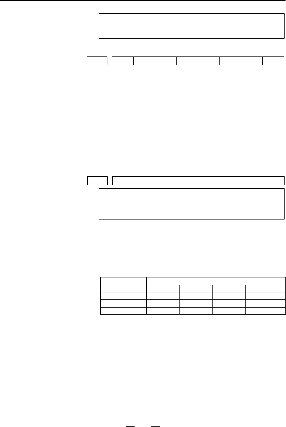
- Page 664. DESCRIPTION OF PARAMETERS B–63180EN/02 NOTE Set this parameter to both master axis and slave axis. #7 #6 #5 #4 #3 #2 #1 #0 1819 CRFx FUPx [Data type] Bit axis FUPx To perform follow–up when the servo is off is set for each axis. 0: The follow–up signal, *FLWU, determines whether follow–up is perf
- Page 67B–63180EN/02 4. DESCRIPTION OF PARAMETERS Setting command multiply (CMR), detection multiply (DMR), and the capacity of the reference counter + DA X CMR Error counter Converter To velocity control least command – increment Feedback pulse Reference counter X DMR Position detector Detection unit Fig.4
- Page 684. DESCRIPTION OF PARAMETERS B–63180EN/02 1821 Reference counter size for each axis NOTE When this parameter has been set, the power must be turned off before operation is continued. [Data type] 2–word axis [Valid data range] 0 to 99999999 Set the size of the reference counter. When using the linear
- Page 69B–63180EN/02 4. DESCRIPTION OF PARAMETERS 1827 In–position width in cutting feed for each axis [Data type] Word axis [Unit of data] Detection unit [Valid data range] 0 to 32767 Set an in–position width for each axis in cutting feed. This parameter is valid when bit 4 (CCI) of parameter No.1801=1. 18
- Page 704. DESCRIPTION OF PARAMETERS B–63180EN/02 1832 Feed stop positioning deviation for each axis [Data type] 2–word axis [Unit of data] Detection unit [Valid data range] 0 to 99999999 Set the feed stop positioning deviation for each axis. If the positioning deviation exceeds the feed stop positioning de
- Page 71B–63180EN/02 4. DESCRIPTION OF PARAMETERS 1851 Backlash compensating value for each axis [Data type] Word axis [Unit of data] Detection unit [Valid data range] –9999 to +9999 Set the backlash compensating value for each axis. When the machine moves in a direction opposite to the reference position r
- Page 724. DESCRIPTION OF PARAMETERS B–63180EN/02 Example: Assume that the following settings have been made. If an abnormal load is detected for the sixth axis, movement along the second, fourth, sixth, and seventh axes is stopped. If an abnormal load is detected for the fourth axis, movement along the fou
- Page 73B–63180EN/02 4. DESCRIPTION OF PARAMETERS Zero point of Reference Scale end position the scale Scale Mark 1 = mark 2 Mark 1 Mark 2 Mark 1 Mark 2 8.0 42.0 8.2 41.8 Parameter No.1821 Parameter No.1882 Parameter No.1883 1885 Maximum allowable value for total travel during torque control [Data type] Wor
- Page 744. DESCRIPTION OF PARAMETERS B–63180EN/02 #7 #6 #5 #4 #3 #2 #1 #0 1901 HFU [Data type] Bit HFU This parameter specifies the type of follow–up to be performed in the torque control mode, at an emergency stop, or at a servo alarm, as follows: 0 : Conventional type 1 : High–speed type #7 #6 #5 #4 #3 #2
- Page 75B–63180EN/02 4. DESCRIPTION OF PARAMETERS #7 #6 #5 #4 #3 #2 #1 #0 1905 PM2 PM1 IO2 IO1 FSL NOTE After this parameter has been set, the power must be turned off then back on for the setting to become effective. [Data type] Bit axis FSL The type of interface used between the servo amplifier and servo
- Page 764. DESCRIPTION OF PARAMETERS B–63180EN/02 IO2 First axis The basic unit of the FSSB I/O module in group 2 is: 0 : Not used. 1 : Used. Second axis The expansion unit of the FSSB I/O module in group 2 is: 0 : Not used. 1 : Used. NOTE 1 In any group, do not specify that only the expansion unit is to be
- Page 77B–63180EN/02 4. DESCRIPTION OF PARAMETERS 1910 Address conversion table value for slave 1 (ATR) 1911 Address conversion table value for slave 2 (ATR) 1912 Address conversion table value for slave 3 (ATR) 1913 Address conversion table value for slave 4 (ATR) 1914 Address conversion table value for sl
- Page 784. DESCRIPTION OF PARAMETERS B–63180EN/02 S Examples of axis configurations and parameter settings (1) Optical cable Power 1–axis 2–axis 2–axis M1 1–axis M2 Mate amplifier amplifier amplifier amplifier X Y Z A B C axis axis axis axis axis axis slave number 1 2 3 4 5 6 7 8 If the connection shown abo
- Page 79B–63180EN/02 4. DESCRIPTION OF PARAMETERS (2) Optical cable Power 1–axis 1–axis 2–axis 1–axis 1–axis Mate amplifier amplifier amplifier amplifier amplifier X B Y Z A C axis axis axis axis axis axis Tandem Tandem (SLAVE) Slave number 1 2 3 4 5 6 If the connection shown above is made, the relationship
- Page 804. DESCRIPTION OF PARAMETERS B–63180EN/02 Connection viewed from Power Mate Servo conrtol unit Connection viewed from FSSB Controlled Axis Address axis number name Servo axis conversion (n–th axis) No. 1020 number table value Slave Axis No. 1023 No. 1910 to number 1919 1 1 X 1–axis 1 0 (No.1910) amp
- Page 81B–63180EN/02 4. DESCRIPTION OF PARAMETERS 1920 Controlled axis number for slave 1 (dedicated to the FSSB setting screen) 1921 Controlled axis number for slave 2 (dedicated to the FSSB setting screen) 1922 Controlled axis number for slave 3 (dedicated to the FSSB setting screen) 1923 Controlled axis
- Page 824. DESCRIPTION OF PARAMETERS B–63180EN/02 Master and slave axis numbers subject to tandem control 1934 (dedicated to the FSSB setting screen) NOTE After this parameter has been set, the power must be turned off then back on for the setting to become effective. [Data type] Byte axis [Valid data range
- Page 83B–63180EN/02 4. DESCRIPTION OF PARAMETERS Start address of the R area to which the DI bit information of the FSSB I/O mod- 1960 ule in group 1 is sent NOTE When this parameter ise set, the power must be turned off before operation is continued. [Data type] Word [Valid data range] The range of values
- Page 844. DESCRIPTION OF PARAMETERS B–63180EN/02 Size of the R area where the bit information to be output to the DO of the FSSB 1963 I/O module in group 1 is stored NOTE When this parameter ise set, the power must be turned off before operation is continued. [Data type] Byte [Unit of data] Byte [Valid dat
- Page 85B–63180EN/02 4. DESCRIPTION OF PARAMETERS Address of the R area to which the DO bit information of the FSSB I/O module 1966 in group 2 is sent NOTE When this parameter ise set, the power must be turned off before operation is continued. [Data type] Word [Valid data range] The range of values that ca
- Page 864. DESCRIPTION OF PARAMETERS B–63180EN/02 #7 #6 #5 #4 #3 #2 #1 #0 EXDVAL2 DVAL2 EXDVAL1 DVAL1 If each bit is “1”, it has the following meaning: DVAL1: A DO alarm condition was detected in the basic unit in group 1. EXDVAL1:A DO alarm condition was detected in the expansion unit in group 1. DVAL2: A
- Page 87B–63180EN/02 4. DESCRIPTION OF PARAMETERS No. Data type Contents 2023 Word axis Number of velocity pulses 2024 Word axis Number of position pulses 2028 Word axis Position gain switching speed 2029 Word axis Effective speed for integral acceleration at low speed 2030 Word axis Effective speed for int
- Page 884. DESCRIPTION OF PARAMETERS B–63180EN/02 No. Data type Contents 2080 Word axis First–order lag time constant for dual position feedback 2081 Word axis Zero width for dual position feedback 2082 Word axis Backlash acceleration stop amount 2083 Word axis Brake control timer (ms) 2084 Word axis Flexib
- Page 89B–63180EN/02 4. DESCRIPTION OF PARAMETERS 4.13 #7 #6 #5 #4 #3 #2 #1 #0 PARAMETERS OF 3001 MHI RWM SON DI/DO [Data type] Bit SON 0 : Starts automatic operation on the falling edge (1 → 0) of the automatic operation start signal (ST). 1 : Starts automatic operation on the rising edge (0 → 1) of the au
- Page 904. DESCRIPTION OF PARAMETERS B–63180EN/02 If, however, a parameter specifies not to make in–position during deceleration, the signal turns to “0” at the end of deceleration. #7 #6 #5 #4 #3 #2 #1 #0 3004 OTH [Data type] Bit OTH The overtravel limit signal is: 0 : Checked 1 : Not checked WARNING For s
- Page 91B–63180EN/02 4. DESCRIPTION OF PARAMETERS The time required to send strobe signals MF, SF, and TF after the M, S, and T codes are sent, respectively. M, S, T code MF, SF, TF signal Delay time Fig.4.13 (a) Delay Time of the strobe signal NOTE The time is counted in units of 8 ms. If the set value is
- Page 924. DESCRIPTION OF PARAMETERS B–63180EN/02 3017 Output time of reset signal RST [Data type] Byte [Unit of data] 16 ms [Valid data range] 0 to 255 To extend the output time of reset signal RST, the time to be added is specified in this parameter. RST signal output time = time veguired for reset + para
- Page 93B–63180EN/02 4. DESCRIPTION OF PARAMETERS 4.14 PARAMETERS OF #7 #6 #5 #4 #3 #2 #1 #0 MDI, DISPLAY, 3100 CEM AND EDIT [Data type] Bit CEM On screens such as the operation history screen and help screen, keys on the MDI panel are indicated: 0 : In English. 1 : With graphics qualifying for CE marking.
- Page 944. DESCRIPTION OF PARAMETERS B–63180EN/02 PPD Relative position display when a coordinate system is set 0 : Not preset 1 : Preset NOTE When PPD is set to 1 and the absolute position display is preset by one of the following, the relative position display is also preset to the same value as the absol
- Page 95B–63180EN/02 4. DESCRIPTION OF PARAMETERS #7 #6 #5 #4 #3 #2 #1 #0 3106 OHS OPH [Data type] Bit OPH The operation history screen is: 0 : Not displayed. 1 : Displayed. OHS Operation history sampling is: 0 : Performed. 1 : Not performed. #7 #6 #5 #4 #3 #2 #1 #0 3107 MDL SOR DNC NAM [Data type] Bit NAM
- Page 964. DESCRIPTION OF PARAMETERS B–63180EN/02 #7 #6 #5 #4 #3 #2 #1 #0 3109 RHD SFM IKY [Data type] Bit IKY On the tool offset screen, soft key [INPUT] is: 0 : Displayed. 1 : Not displayed. SFM 0 : Displays the soft keys (menu) for pattern data input screen selection on page 2 of the offset/setting scree
- Page 97B–63180EN/02 4. DESCRIPTION OF PARAMETERS #7 #6 #5 #4 #3 #2 #1 #0 3112 OPH EAH NOTE When this parameter is set, the power must be turned off before operation is continued. [Data type] Bit EAH Messages of the exfernal alam/macro alarm in alarm history: 0 : Not recorded 1 : Recorded OPH The operation
- Page 984. DESCRIPTION OF PARAMETERS B–63180EN/02 #7 #6 #5 #4 #3 #2 #1 #0 AS1 3118 [Data type] Bit AS1 When the actual spindle speeds (SACT) of the spindle is displayed, the value is: 0 : The value calculated based on the feedback pulses from the position coder. 1 : The value calculated from the spindle mot
- Page 99B–63180EN/02 4. DESCRIPTION OF PARAMETERS [Example] When the configuration of axes is X in path 1 and X in path 2 (1) Setting for path 1 Parameter 3131x . . . 65 (A) XA is displayed as axis names. (2) Setting for path 2 Parameter 3131x . . . 66 (B) XB is displayed as axis names. #7 #6 #5 #4 #3 #2 #1
- Page 1004. DESCRIPTION OF PARAMETERS B–63180EN/02 3170 Number of connected Power Mate units [Data type] Byte [Valid data range] 0 to 16 (128 to 144) CRTMAX When the CRT/MDI is shared by multiple Power Mate units, set the number of connected Power Mate units. In this parameter, set equipment parameter #0 onl
- Page 101B–63180EN/02 4. DESCRIPTION OF PARAMETERS #7 #6 #5 #4 #3 #2 #1 #0 3202 PSR CPD NE9 OSR CND OLV NE8 [Data type] Bit NE8 Editing of subprograms with program numbers 8000 to 8999 0 : Not inhibited 1 : Inhibited The following edit operations are disabled: (1) Program deletion (Even when deletion of all
- Page 1024. DESCRIPTION OF PARAMETERS B–63180EN/02 CPD When an NC program is deleted, a confirmation message and confirmation soft key are: 0 : Not output. 1 : Output. PSR Search for the program number of a protected program 0 : Disabled 1 : Enabled #7 #6 #5 #4 #3 #2 #1 #0 3203 MCL MER MIE [Data type] Bit MZ
- Page 103B–63180EN/02 4. DESCRIPTION OF PARAMETERS P8E Editing of subprograms 80000000 to 89999999 is: 0 : Not inhibited 1 : Inhibited The following editing types become impossible. (1) Program deletion (Programs numbered in the 80000000 range will not be deleted even if all–program deletion is specified.) (
- Page 1044. DESCRIPTION OF PARAMETERS B–63180EN/02 #7 #6 #5 #4 #3 #2 #1 #0 3205 CHG COL [Data type] Bit COL When a program is displayed or output, any colons (:) in the comments of the program are: 0 : Converted to letter O 1 : Displayed or output as is CHG When the change function of the extended edit funct
- Page 105B–63180EN/02 4. DESCRIPTION OF PARAMETERS NOTE The functions of the signals depend on whether KEY=0 or KEY=1. When KEY = 0: – KEY1: Enables a tool offset value to be input. – KEY2: Enables setting data and macro variables to be input. – KEY3: Enables program registration and editing. – KEY4: Enables
- Page 1064. DESCRIPTION OF PARAMETERS B–63180EN/02 4.15 #7 #6 #5 #4 #3 #2 #1 #0 PARAMETERS OF 3401 ABS MAB DPI PROGRAMS [Data type] Bit DPI When a decimal point is omitted in an address that can include a decimal point 0 : The least input increment is assumed. 1 : The unit of mm, inches, or second is assumed
- Page 107B–63180EN/02 4. DESCRIPTION OF PARAMETERS #7 #6 #5 #4 #3 #2 #1 #0 3403 AD2 CIR [Data type] Bit CIR When neither the distance (I, J, K) from a start point to the center nor an arc radius (R) is specified in circular interpolation (G02, G03): 0 : The tool moves to an end point by linear interpolation.
- Page 1084. DESCRIPTION OF PARAMETERS B–63180EN/02 EOR When the end–of–record mark (%) is read during program execution: 0 : P/S alarm No.5010 occurs. (Automatic operation is stopped, and the system enters the alarm state.) 1 : No alarm occurs. (Automatic operation is stopped, and the system is reset.) M3B T
- Page 109B–63180EN/02 4. DESCRIPTION OF PARAMETERS 3411 M code preventing buffering 1 3412 M code preventing buffering 2 3413 M code preventing buffering 3 L L 3420 M code preventing buffering 10 [Data type] Byte [Valid data range] 0 to 255 Set M codes that prevent buffering the following blocks. If processi
- Page 1104. DESCRIPTION OF PARAMETERS B–63180EN/02 4.16 PARAMETERS OF 3620 Number of the pitch error compensation position for the reference position for each axis PITCH ERROR COMPENSATION NOTE (OPTIONAL When this parameter is set, the power must be turned off FUNCTION WITH before operation is continued. POW
- Page 111B–63180EN/02 4. DESCRIPTION OF PARAMETERS Number of the pitch error compensation position at extremely positive position 3622 for each axis NOTE When this parameter is set, the power must be turned off before operation is continued. [Data type] Word axis [Unit of data] Number [Valid data range] 0 to
- Page 1124. DESCRIPTION OF PARAMETERS B–63180EN/02 3624 Interval between pitch error compensation positions for each axis NOTE When this parameter is set, the power must be turned off before operation is continued. [Data type] 2–word axis [Unit of data] Increment system IS–A IS–B IS–C Unit Millimeter machine
- Page 113B–63180EN/02 4. DESCRIPTION OF PARAMETERS No.of the compensation position of the reference position + (Machine stroke length in the positive direction/Interval between the compensation positions) = 40 + 800/50 = 56 The correspondence between the machine coordinate and the compensation position No.is
- Page 1144. DESCRIPTION OF PARAMETERS B–63180EN/02 The No.of the farthest compensation position in the positive direction is as follows: No.of the compensation position of the reference position + (Move amount per rotation/Interval between the compensation position) = 60 + 360/45 = 68 The correspondence betw
- Page 115B–63180EN/02 4. DESCRIPTION OF PARAMETERS Pitch error compensation value +4 (absolute value) +3 Reference position +2 +1 0 0 90 135 180 225 270 315 45 90 135 180 225 270 315 45 (deg) –1 –2 –3 –4 109
- Page 1164. DESCRIPTION OF PARAMETERS B–63180EN/02 4.17 #7 #6 #5 #4 #3 #2 #1 #0 PARAMETERS OF ISI 3701 SPINDLE CONTROL NOTE When this parameter is set, the power must be turned off before operation is continued. ISI The serial interface for the spindles is: 0 : Used. 1 : Not used. NOTE It is used when the CN
- Page 117B–63180EN/02 4. DESCRIPTION OF PARAMETERS GST The SOR signal is used for: 0 : Spindle orientation 1 : Gear shift SGB Gear switching method 0 : Method A (Parameters 3741 to 3743 for the maximum spindle speed at each gear are used for gear selection.) 1 : Method B (Parameters 3751 and 3752 for the spi
- Page 1184. DESCRIPTION OF PARAMETERS B–63180EN/02 ORM Voltage polarity during spindle orientation 0 : Positive 1 : Negative TCW, CWM Voltage polarity when the spindle speed voltage is output TCW CWM Voltage polarity 0 0 Both M03 and M04 positive 0 1 Both M03 and M04 negative 1 0 M03 positive, M04 negative 1
- Page 119B–63180EN/02 4. DESCRIPTION OF PARAMETERS Compensation value for the offset voltage of the analog output of the spindle 3731 speed [Data type] Word [Unit of data] Velo [Valid data range] –1024 to+1024 Set compesation value for the offset voltage of the analog output of the spindle speed. Set value =
- Page 1204. DESCRIPTION OF PARAMETERS B–63180EN/02 Minimum clamp speed of the spindle motor 3735 [Data type] Word [Valid data range] 0 to 4095 Set the minimum clamp speed of the spindle motor. Minimum clamp speed of the spindle motor Set value = × 4095 Maximum spindle motor speed Maximum clamp speed of the s
- Page 121B–63180EN/02 4. DESCRIPTION OF PARAMETERS Maximum spindle speed for gear 1 3741 Maximum spindle speed for gear 2 3742 Maximum spindle speed for gear 3 3743 Maximum spindle speed for gear 4 3744 [Data type] Word [Unit of data] min–1 [Valid data range] 0 to 32767 Set the maximum spindle speed correspo
- Page 1224. DESCRIPTION OF PARAMETERS B–63180EN/02 Spindle motor speed when switching from gear 1 to gear 2 3751 Spindle motor speed when switching from gear 2 to gear 3 3752 [Data type] Word [Valid data range] 0 to 4095 For gear switching method B, set the spindle motor speed when the gears are switched. Sp
- Page 123B–63180EN/02 4. DESCRIPTION OF PARAMETERS Spindle speed when switching from gear 1 to gear 2 during tapping 3761 Spindle speed when switching from gear 2 to gear 3 during tapping 3762 [Data type] Word [Unit of data] min–1 [Valid data range] 0 to 32767 When method B is selected (SGT,#3 of parameter 3
- Page 1244. DESCRIPTION OF PARAMETERS B–63180EN/02 Minimum spindle speed in constant surface speed control mode (G96) 3771 [Data type] Word [Unit of data] min–1 [Valid data range] 0 to 32767 Set the minimum spindle speed in the constant surface speed control mode (G96). The spindle speed in constant surface
- Page 125B–63180EN/02 4. DESCRIPTION OF PARAMETERS Table 4.17 (a) Parameters for Serial Interface Spindle Amplifier (α series, S series) (1/7) No. Data type Description 4000 Bit Bit parameter 4001 Bit Bit parameter 4002 Bit Bit parameter 4003 Bit Bit parameter 4004 Bit Bit parameter 4005 Bit Bit parameter 40
- Page 1264. DESCRIPTION OF PARAMETERS B–63180EN/02 Table 4.17 (a) Parameters for Serial Interface Spindle Amplifier (α series, S series) (2/7) No. Data type Description 4060 Word Position gain during orientation (HIGH) 4061 Word Position gain during orientation (MEDIUM HIGH) 4062 Word Position gain during or
- Page 127B–63180EN/02 4. DESCRIPTION OF PARAMETERS Table 4.17 (a) Parameters for Serial Interface Spindle Amplifier (α series, S series) (3/7) No. Data type Description 4120 Word Dead zone compensation data 4121 Word Time constant for changing the torque 4122 Word Velocity filter 4123 Word Overload detection
- Page 1284. DESCRIPTION OF PARAMETERS B–63180EN/02 Table 4.17 (a) Parameters for Serial Interface Spindle Amplifier (α series, S series) (4/7) No. Data type Description 4170 Word Overload current alarm detection level (for high speed characteristic) 4171 Word Arbitrary gear data between spindle and Position
- Page 129B–63180EN/02 4. DESCRIPTION OF PARAMETERS Table 4.17 (a) Parameters for Serial Interface Spindle Amplifier (α series, S series) (5/7) No. Data type Description 4230 Word MS signal gain adjustment 4231 Word Regenerative power limit 4232 Word Delay time up to motor power shut–off 4233 Word Acceleratio
- Page 1304. DESCRIPTION OF PARAMETERS B–63180EN/02 Table 4.17 (a) Parameters for Serial Interface Spindle Amplifier (α series, S series) (6/7) No. Data type Description 4280 Word Time constant of voltage filter for electromotive force compensation 4281 Word Word Spindle load monitor torque constant (for low–
- Page 131B–63180EN/02 4. DESCRIPTION OF PARAMETERS Table 4.17 (a) Parameters for Serial Interface Spindle Amplifier (α series, S series) (7/7) No. Data type Description 4340 Word 4341 Word Word Abnormal load detection level 4342 Word Reserved 4343 Word N pulse suppress 4344 Word 4345 Word 4346 Word Incomplet
- Page 1324. DESCRIPTION OF PARAMETERS B–63180EN/02 Notes on parameters of the spindle amplifier with the serial interface NOTE 1 Among the parameters of the spindle amplifier with the serial interface, parameters Nos. 4015 and 4191 cannot be changed by the users. These parameters require to assign optional s
- Page 133B–63180EN/02 4. DESCRIPTION OF PARAMETERS 4.18 PARAMETERS OF #7 #6 #5 #4 #3 #2 #1 #0 TOOL 5001 EVO TAL TLB TLC COMPENSATION [Data type] Bit type TLC Tool length compensation 0 : Tool length compensation A or B (Conforms to TLB in parameter No.5001) 1 : Tool length compensation C TLB Tool length comp
- Page 1344. DESCRIPTION OF PARAMETERS B–63180EN/02 4.19 PARAMETERS OF CANNED CYCLES 4.19.1 #7 #6 #5 #4 #3 #2 #1 #0 Parameter of canned M5B M5T RD2 RD1 FXY Cycle for Drilling 5101 [Data type] Bit FXY The drilling axis in the drilling canned cycle is: 0 : Always the first–axis 1 : The axis selected by the prog
- Page 135B–63180EN/02 4. DESCRIPTION OF PARAMETERS Return value of high–speed peck drilling cycle G73 5114 [Data type] Word [Unit of data] Increment system IS-A IS-B IS-C Unit Millimeter input 0.01 0.001 0.001 mm Inch input 0.001 0.0001 0.0001 inch [Valid data range] 0 to 32767 This parameter sets the return
- Page 1364. DESCRIPTION OF PARAMETERS B–63180EN/02 4.20 PARAMETERS OF #7 #6 #5 #4 #3 #2 #1 #0 RIGID TAPPING FHD PCP DOV CRG VGR G84 5200 [Data type] Bit G84 Method for specifying rigid tapping 0 : An M code specifying the rigid tapping mode is specified prior to the issue of the G84 (or G74) command. (See pa
- Page 137B–63180EN/02 4. DESCRIPTION OF PARAMETERS Rigid tapping mode specification M code 5210 [Data type] Byte [Valid data range] 0 to 255 This parameter sets an M code that specifies the rigid tapping mode. To set an M code larger than 255, set it to parameter No.5212. NOTE 1 The M code is judged to be 29
- Page 1384. DESCRIPTION OF PARAMETERS B–63180EN/02 Number of spindle gear teeth (first–stage gear) 5221 Number of spindle gear teeth (second–stage gear) 5222 Number of spindle gear teeth (third–stage gear) 5223 [Data type] Word [Valid data range] 1 to 32767 When an arbitrary gear ratio is used in rigid tappi
- Page 139B–63180EN/02 4. DESCRIPTION OF PARAMETERS Maximum spindle speed in rigid tapping (first–stage gear) 5241 Maximum spindle speed in rigid tapping (second–stage gear) 5242 Maximum spindle speed in rigid tapping (third–stage gear) 5243 [Data type] 2–word [Unit of data] min–1 [Valid data range] Spindle p
- Page 1404. DESCRIPTION OF PARAMETERS B–63180EN/02 Time constant for the spindle and tapping axis in extraction operation (first–stage gear) 5271 Time constant for the spindle and tapping axis in extraction operation 5272 (second–stage gear) Time constant for the spindle and tapping axis in extraction operat
- Page 141B–63180EN/02 4. DESCRIPTION OF PARAMETERS NOTE To use a varied loop gain on a gear–by–gear basis, set parameter No.5280 to 0, and set a loop gain for each gear in parameters No.5281 through No.5283. The specification of a loop gain on a gear–by–gear basis is disabled if parameter No.5280 is set to a
- Page 1424. DESCRIPTION OF PARAMETERS B–63180EN/02 Examples When the spindle motor, spindle, and position coder are connected as shown left, let the variables be as follows: Spindle Motor E = 1.667 (V) (A motor speed of 6000 rpm corresponds to 10 V.) Position L = 360_ (One rotation of the spindle corresponds
- Page 143B–63180EN/02 4. DESCRIPTION OF PARAMETERS NOTE When a high–resolution detector is used, the unit must be multiplied by 10. Limit value of spindle positioning deviation during movement in rigid tapping. 5311 [Data type] Word type [Unit of data] Detection unit [Valid data range] 1 to 32767 This parame
- Page 1444. DESCRIPTION OF PARAMETERS B–63180EN/02 Positional deviation limit imposed while the spindle is stopped in rigid tapping 5313 [Data type] Word [Unit of data] Detection unit [Valid data range] 1 to 32767 This parameter is used to set a positional deviation limit imposed while the spindle is stopped
- Page 145B–63180EN/02 4. DESCRIPTION OF PARAMETERS 4.21 PARAMETERS OF POLAR COORDINATE INTERPOLATION 5460 Axis (linear axis) specification for polar coordinate interpolation 5461 Axis (rotary axis) specification for polar coordinate interpolarion [Data type] Byte [Valid data range] 1, 2, 3, ... control axes
- Page 1464. DESCRIPTION OF PARAMETERS B–63180EN/02 4.22 PARAMETERS OF STRAIGHTNESS COMPENSATION 5711 Axis number of moving axis [Data type] Byte [Unit of data] Number (When 0, compensation is not performed.) [Valid data range] 1, 2, 3, ...Number of controlled axes Set the axis numbers of moving axes. 5721 Ax
- Page 147B–63180EN/02 4. DESCRIPTION OF PARAMETERS 4.23 PARAMETERS OF #7 #6 #5 #4 #3 #2 #1 #0 CUSTOM MACROS 6000 SBM HGO MGO G67 [Data type] Bit G67 If the macro continuous–state call cancel command (G67) is specified when the macro continuous–state call mode (G66) is not set: 0 : P/S alarm No.122 is issued.
- Page 1484. DESCRIPTION OF PARAMETERS B–63180EN/02 CCV Custom macro’s common variables Nos. 100 through 199 0: Cleared to “vacant” by reset 1: Not cleared by reset CLV Custom macro’s local variables Nos. 1 through 33 0: Cleared to “vacant” by reset 1: Not cleared by reset #7 #6 #5 #4 #3 #2 #1 #0 6003 MUS MCY
- Page 149B–63180EN/02 4. DESCRIPTION OF PARAMETERS #7 #6 #5 #4 #3 #2 #1 #0 6010 *7 *6 *5 *4 *3 *2 *1 *0 6011 =7 =6 =5 =4 =3 =2 =1 =0 6012 #7 #6 #5 #4 #3 #2 #1 #0 6013 [7 [6 [5 [4 [3 [2 [1 [0 6014 ]7 ]6 ]5 ]4 ]3 ]2 ]1 ]0 [Data type] Bit These parameters are used to input/output macro statements. The numeral o
- Page 1504. DESCRIPTION OF PARAMETERS B–63180EN/02 6050 G code that calls the custom macro of program number 9010 6051 G code that calls the custom macro of program number 9011 6052 G code that calls the custom macro of program number 9012 6053 G code that calls the custom macro of program number 9013 6054 G
- Page 151B–63180EN/02 4. DESCRIPTION OF PARAMETERS 6080 M code that calls the custom macro of program number 9020 6081 M code that calls the custom macro of program number 9021 6082 M code that calls the custom macro of program number 9022 6083 M code that calls the custom macro of program number 9023 6084 M
- Page 1524. DESCRIPTION OF PARAMETERS B–63180EN/02 4.24 When bit 3 (SFM) of parameter No. 3109 is set to 0 PARAMETERS OF (1) Pressing OFFSET SETTING displays page 1 of soft keys. PATTERN DATA [OFFSET] [SETTING] [ ][ ] [(OPRT)] INPUT (2) Pressing the next page soft key ( ) displays page 2 of soft keys. [MACRO
- Page 153B–63180EN/02 4. DESCRIPTION OF PARAMETERS 4.25 PARAMETERS OF #7 #6 #5 #4 #3 #2 #1 #0 OPTIMUM 6131 EOA OAD ACCELERATION NOTE When this parameter is set, the power must be turned off before operation is continued. [Data type] Bit axis OAD The function for positioning by optimum acceleration is: 0 : Di
- Page 1544. DESCRIPTION OF PARAMETERS B–63180EN/02 Specify the positioning distance when the function for positioning by optimum acceleration is used. (To be set for each axis) NOTE 1 The set values must satisfy: D1 < D2 < D3 2 Switching is possible through up to four stages. Set up D3 = 99999999, for exampl
- Page 155B–63180EN/02 4. DESCRIPTION OF PARAMETERS NOTE 1 The set values must satisfy: D1 < D2 < D3 < D4 < D5 < D6 < D7 2 Switching is possible through up to seven stages. Set up D4 = 99999999, for example, if the first to fourth stages are to be used. 3 These parameters specify a distance for the respective
- Page 1564. DESCRIPTION OF PARAMETERS B–63180EN/02 6181 First–stage rapid traverse servo loop gain 6182 Second–stage rapid traverse servo loop gain 6183 Third–stage rapid traverse servo loop gain 6184 Fourth–stage rapid traverse servo loop gain 6185 Fifth–stage rapid traverse servo loop gain 6186 Third–stage
- Page 157B–63180EN/02 4. DESCRIPTION OF PARAMETERS 4.26 PARAMETERS OF #7 #6 #5 #4 #3 #2 #1 #0 SKIP FUNCTION 6200 SKF SK0 GSK [Data type] Bit GSK In skip cutting (G31), the skip signal SKIPP (bit 6 of G006) is: 0 : Not used as a skip signal. 1 : Used as a skip signal. SK0 This parameter specifies whether the
- Page 1584. DESCRIPTION OF PARAMETERS B–63180EN/02 0 : The skip signal corresponding to the bit is disabled. 1 : The skip signal corresponding to the bit is enabled. Multi–step skip function G04 Command G31 G04Q1 G31P2 G31P3 G31P4 G31P1 G04Q2 Input G04Q2 G04Q3 G04Q4 G04Q1 G04Q3 signal G04Q4 SKIP 1S1 2S1 3S1
- Page 159B–63180EN/02 4. DESCRIPTION OF PARAMETERS NOTE The change to this setting takes effect next time the power is turned on. #7 #6 #5 #4 #3 #2 #1 #0 6218 DI7 DI6 DI5 DI4 DI3 DI2 DI1 DI0 [Data type] Bit DIn When the high–speed skip signal is input, the nth (system variables 9n00 to 9n99) buffer is loaded
- Page 1604. DESCRIPTION OF PARAMETERS B–63180EN/02 NOTE The change to this setting takes effect next time the power is turned on. 6230 Axis number of an axis assigned to buffer 1 6231 Axis number of an axis assigned to buffer 2 6232 Axis number of an axis assigned to buffer 3 6233 Axis number of an axis assi
- Page 161B–63180EN/02 4. DESCRIPTION OF PARAMETERS 6240 Compensation value for signal 1 6241 Compensation value for signal 2 6242 Compensation value for signal 3 6243 Compensation value for signal 4 6244 Compensation value for signal 5 6245 Compensation value for signal 6 6246 Compensation value for signal 7
- Page 1624. DESCRIPTION OF PARAMETERS B–63180EN/02 4.27 PARAMETERS OF EXTERNAL DATA #7 #6 #5 #4 #3 #2 #1 #0 INPUT/OUTPUT 6300 ESR [Data type] Bit ESR External program number search 0 : Disabled 1 : Enabled 4.28 PARAMETERS OF PICTURE DISPLAY #7 #6 #5 #4 #3 #2 #1 #0 6550 DSG [Data type] Bit DSG The soft keys f
- Page 163B–63180EN/02 4. DESCRIPTION OF PARAMETERS 4.29 PARAMETERS OF DISPLAYING OPERATION TIME AND NUMBER OF #7 #6 #5 #4 #3 #2 #1 #0 PARTS 6700 NCT PCM [Data type] Bit PCM M code that counts the total number of machined parts and the number of machined parts 0 : M02, or M30, or an M code specified by parame
- Page 1644. DESCRIPTION OF PARAMETERS B–63180EN/02 6712 Total number of machined parts This parameter can be set at “Setting screen”. [Data type] 2–word [Unit of data] One piece [Valid data range] 0 to 99999999 This parameter sets the total number of machined parts. The total number of machined parts is coun
- Page 165B–63180EN/02 4. DESCRIPTION OF PARAMETERS 6752 Operation time (integrated value of time during automatic operation) II This parameter can be set at “Setting screen”. [Data type] 2–word [Unit of data] One minute [Valid data range] 0 to 99999999 This parameter displays the integrated value of time dur
- Page 1664. DESCRIPTION OF PARAMETERS B–63180EN/02 6757 Operation time (integrated value of one automatic operation time) I This parameter can be set at “Setting screen”. [Data type] 2–word [Unit of data] One ms [Valid data range] 0 to 60000 6758 Operation time (integrated value of one automatic operation ti
- Page 167B–63180EN/02 4. DESCRIPTION OF PARAMETERS 4.30 PARAMETERS OF POSITION SWITCH #7 #6 #5 #4 #3 #2 #1 #0 FUNCTIONS 6901 IGP [Data type] Bit IGP During follow–up for the absolute position detector, position switch signals are: 0 : Output 1 : Not output 6910 Axis corresponding to the first position switch
- Page 1684. DESCRIPTION OF PARAMETERS B–63180EN/02 6930 Maximum operation range of the first position switch 6931 Maximum operation range of the second position switch 6932 Maximum operation range of the third position switch 6933 Maximum operation range of the fourth position switch 6934 Maximum operation r
- Page 169B–63180EN/02 4. DESCRIPTION OF PARAMETERS 4.31 PARAMETERS OF MANUAL HANDLE FEED, HANDLE INTERRUPTION DIRECTION #7 #6 #5 #4 #3 #2 #1 #0 7100 HPF HCL IHD THD [Data type] Bit THD Manual pulse generator in TEACH IN JOG mode 0 : Invalid 1 : Valid IHD The travel increment for manual handle interrupt is: 0
- Page 1704. DESCRIPTION OF PARAMETERS B–63180EN/02 #7 #6 #5 #4 #3 #2 #1 #0 7104 NJH [Data type] Bit NJH Manual handle feed in the jog mode and incremental feed in the manual handle feed mode are: 0 : Enabled. 1 : Disabled. When NJH is set to 1 When NJH is set to 0 Manual Manual Jog feed Jog feed handle feed
- Page 171B–63180EN/02 4. DESCRIPTION OF PARAMETERS 7114 Manual handle feed magnification n [Data type] Word [Unit of data] One time [Valid data range] 1 to 1000 This parameter sets the magnification when manual handle feed movement selection signals MP1 and MP2 are set to 1. Movement selection signal Movemen
- Page 1724. DESCRIPTION OF PARAMETERS B–63180EN/02 4.32 PARAMETERS OF REFERENCE POSITION SETTING WITH MECHANICAL STOPPER 7181 First withdrawal distance in reference position setting with mechanical stopper [Data type] 2–word axis [Unit of data] Increment system IS–A IS–B IS–C Unit Millimeter machine 0.01 0.0
- Page 173B–63180EN/02 4. DESCRIPTION OF PARAMETERS 7183 First butting feedrate in reference position setting with mechanical stopper [Data type] Word axis [Unit of data and valid range] Valid data range Increment system Unit of data IS–A, IS–B IS–C Millimeter machine 1 mm/min 30 to 15000 30 to 12000 Inch mac
- Page 1744. DESCRIPTION OF PARAMETERS B–63180EN/02 4.33 PARAMETERS OF SOFTWARE OPERATOR’S PANEL #7 #6 #5 #4 #3 #2 #1 #0 7200 OP7 OP6 OP5 OP4 OP3 OP2 OP1 [Data type] Bit OP1 Mode selection on software operator’s panel 0 : Not performed 1 : Performed OP2 JOG feed axis select and JOG rapid traverse buttons on s
- Page 175B–63180EN/02 4. DESCRIPTION OF PARAMETERS 7210 PLSKY1 [Data type] Bit [Valid data range] 1, 2, 3, 4, 6, 7, 8, 9 This parameter specifies a key value used with the + direction key for the first jog feed axis on the software operator’s panel. 7211 MNSKY1 [Data type] Bit [Valid data range] 1, 2, 3, 4,
- Page 1764. DESCRIPTION OF PARAMETERS B–63180EN/02 7216 PLSKY4 [Data type] Bit [Valid data range] 1, 2, 3, 4, 6, 7, 8, 9 This parameter specifies a key value used with the + direction key for the fourth jog feed axis on the software operator’s panel. 7217 MNSKY4 [Data type] Bit [Valid data range] 1, 2, 3, 4,
- Page 177B–63180EN/02 4. DESCRIPTION OF PARAMETERS Example These parameters set the OPERATOR’S PANEL O1234 N5678 names of the SIGNAL1 : OFF ON general–purpose switches SIGNAL2 : OFF ON (SIGNAL 1 through SIGNAL3 : OFF ON SIGNAL 8) on the SIGNAL4 : OFF ON software operator’s panel SIGNAL5 : OFF ON as described
- Page 1784. DESCRIPTION OF PARAMETERS B–63180EN/02 4.34 PARAMETERS OF THE EXTERNAL #7 #6 #5 #4 #3 #2 #1 #0 PULSE INPUT 7670 EXH [Data type] Byte EXH 0 : Sets an axis and magnification for external pulse input by using DI signals 1 : Sets an axis and magnification for external pulse input by using parameters
- Page 179B–63180EN/02 4. DESCRIPTION OF PARAMETERS 7710 Setting of an axis number for movement along an axis by external pulses [Data type] Byte [Valid data range] 1, 2, ..., number of controlled axes If 0 is specified, no movement along an axis is made by external pulses. NOTE This parameter is valid when b
- Page 1804. DESCRIPTION OF PARAMETERS B–63180EN/02 4.35 PARAMETERS OF AXIS CONTROL BY #7 #6 #5 #4 #3 #2 #1 #0 PMC 8001 SKE AUX NCC RDE OVE MLE [Data type] Bit MLE Whether all axis machine lock signal MLK is valid for PMC–controlled axes 0 : Valid 1 : Invalid OVE Signals related to dry run and override used i
- Page 181B–63180EN/02 4. DESCRIPTION OF PARAMETERS #7 #6 #5 #4 #3 #2 #1 #0 8002 FR2 FR1 PF2 PF1 F10 SUE DWE RPD [Data type] Bit RPD Rapid traverse rate for PMC–controlled axes 0 : Feedrate specified with parameter No.1420 1 : Feedrate specified with the feedrate data in an axis control command DWE Minimum ti
- Page 1824. DESCRIPTION OF PARAMETERS B–63180EN/02 #7 #6 #5 #4 #3 #2 #1 #0 PIM 8003 EA2 PIM NOTE When this parameter is set, the power must be turned off before operation is continued. [Data type] Bit PIM When only the axes controlled by the PMC are used, the linear axis is: 0: Influenced by inch/millimeter
- Page 183B–63180EN/02 4. DESCRIPTION OF PARAMETERS DSL If the selection of an axis is changed when PMC axis selection is disabled: 0 : P/S alarm No.139 is issued. 1 : The change is valid, and no alarm is issued for an unspecified system. NCI In axis control by the PMC, a position check at the time of deceler
- Page 1844. DESCRIPTION OF PARAMETERS B–63180EN/02 8010 Selection of the DI/DO group for each axis controlled by the PMC [Data type] Byte axis [Valid data range] 1 to Number of Controlled axes Specify the DI/DO group to be used to specify a command for each PMC–controlled axis. Value Description 1 DI/DO grou
- Page 185B–63180EN/02 4. DESCRIPTION OF PARAMETERS 8028 Linear acceleration/deceleration time constant or bell–shaped acceleration/de- celeration time constant T1 for speed command–based continuous feed under PMC axis control for each axis [Data type] Word axis [Unit of data] msec/1000 min–1 [Valid data rang
- Page 1864. DESCRIPTION OF PARAMETERS B–63180EN/02 4.36 PARAMETERS OF ELECTRONIC CAM #7 #6 #5 #4 #3 #2 #1 #0 8081 EXD TYB ECM NOTE When this parameter is set, the power must be turned off before operation is continued. [Data type] Bit ECM The electronic cam function is: 0 : Not used. 1 : Used. TYB The specif
- Page 187B–63180EN/02 4. DESCRIPTION OF PARAMETERS 8086 Axis number for a cam shaft when the electronic cam function is used NOTE When this parameter is set, the power must be turned off before operating is continued. [Data type] Byte [Valid data range] 1 to maximum number of control axes Specify an axis num
- Page 1884. DESCRIPTION OF PARAMETERS B–63180EN/02 NOTE 1 An axis number assigned to a cam shaft cannot be selected as a tracking axis. 2 Keep the bits for axes not used as tracking axes at 0. 8088 Number of cam figure data items NOTE When this parameter ise set, the power must be turned off before operating
- Page 189B–63180EN/02 4. DESCRIPTION OF PARAMETERS 4.37 PARAMETERS OF TWO–PATH #7 #6 #5 #4 #3 #2 #1 #0 NWR CONTROL 8100 [Data type] Bit NWR For two–path control, each path is: 0 : Not activated separately. 1 : Activated separately. NOTE If you want to use two–path control, set also the EEP parameter (bit 3 o
- Page 1904. DESCRIPTION OF PARAMETERS B–63180EN/02 4.38 PARAMETERS OF DEVICE INPUT 8290 Device number [Data type] Word axis Set the device number for a device to which pulses are to be applied manually. This parameter is reserved for future expansion. Set the values listed below for the time being. First axi
- Page 191B–63180EN/02 4. DESCRIPTION OF PARAMETERS 8294 Device limit [Data type] Word axis [Valid data range] 0 to 10000 Set a limit value per pulse for the device. If a pulse that exceeds the limit is input, clamping is made at the limit speed. If 0 or any value out of the valid data range is specified, no
- Page 1924. DESCRIPTION OF PARAMETERS B–63180EN/02 4.39 PARAMETERS OF SIMPLE #7 #6 #5 #4 #3 #2 #1 #0 SYNCHRONOUS 8301 SOF CONTROL [Data type] Bit SOF The synchronization funciton in simple synchronous control (one pair) is: 0 : Not used. 1 : Used. #7 #6 #5 #4 #3 #2 #1 #0 8302 ATS ATE NOTE When this parameter
- Page 193B–63180EN/02 4. DESCRIPTION OF PARAMETERS NOTE When starting automatic setting for grid positioning, set ASX to 1. Upon the completion of setting, ASX is automatically set to 0. SFX In simple synchronous control, the synchronization function is: 0 : Not used. 1 : Used. 8311 Axis number of master axi
- Page 1944. DESCRIPTION OF PARAMETERS B–63180EN/02 Limit of the difference between the amount of positioning deviation of the master 8313 and slave axes (Synchronous control one pair) [Data type] Word [Unit of data] Detection unit [Valid data range] 0 to 32767 Set the limit of the difference between the amou
- Page 195B–63180EN/02 4. DESCRIPTION OF PARAMETERS Difference between reference counters for master and slave axes 8316 (Synchronous control one pair) NOTE When this parameter is set, the power must be turned off before operation is continued. [Data type] 2–word [Data unit] Detection unit [Valid data range]
- Page 1964. DESCRIPTION OF PARAMETERS B–63180EN/02 8325 Maximum compensation value for synchronization [Data type] Word axis [Unit of data] Detection unit [Valid data range] 0 to 32767 This parameter sets the maximum compensation value for synchronization. If a compensation value exceeds the value specified
- Page 197B–63180EN/02 4. DESCRIPTION OF PARAMETERS 4.40 PARAMETERS OF MULTIAXIS 8380 SYNCHRONIZATION Axis number for a parent axis used by the multiaxis synchronization function [Data type] Word axis [Valid data range] 0 to 8 Specify a parent axis number for a child axis under synchronization control. There
- Page 1984. DESCRIPTION OF PARAMETERS B–63180EN/02 4.41 PARAMETERS OF HIGH–SPEED POSITION SWITCHES #7 #6 #5 #4 #3 #2 #1 #0 8500 E08 E07 E06 E05 E04 E03 E02 E01 8501 E16 E15 E14 E13 E12 E11 E10 E09 [Data type] Bit E01 to E16 The corresponding high–speed position switch is: 0 : Enabled. 1 : Disabled. (The outp
- Page 199B–63180EN/02 4. DESCRIPTION OF PARAMETERS #7 #6 #5 #4 #3 #2 #1 #0 8508 A08 A07 A06 A05 A04 A03 A02 A01 8509 A16 A15 A14 A13 A12 A11 A10 A09 [Data type] Bit A01 to A16 The signal is turned on when the corresponding high–speed position switch passes through the machine coordinate position set in param
- Page 2004. DESCRIPTION OF PARAMETERS B–63180EN/02 8516 Maximum allowable number of high–speed position switches [Data type] Word [Valid data range] 1 to 16 Specify the maximum allowable number of high–speed position switches. NOTE D The number of high–speed position switches specified in this parameter is t
- Page 201B–63180EN/02 4. DESCRIPTION OF PARAMETERS Example: If parameter No. 8516 = 16 and parameter No. 8517 = 1000, the relationships between the Y signal and the high–speed position switch number are as follows: Y1000#0 ––– first high–speed position switch signal Y1000#1 ––– second high–speed position swi
- Page 2024. DESCRIPTION OF PARAMETERS B–63180EN/02 8520 Axis corresponding to the first high–speed position switch 8521 Axis corresponding to the second high–speed position switch 8522 Axis corresponding to the third high–speed position switch 8523 Axis corresponding to the fourth high–speed position switch
- Page 203B–63180EN/02 4. DESCRIPTION OF PARAMETERS 8550 Maximum value of the operation range of the first high–speed position switch (for normal type) or position where the first high–speed position switch is turned on (for direction reversing type) 8551 Maximum value of the operation range of the third high
- Page 2044. DESCRIPTION OF PARAMETERS B–63180EN/02 [Data type] Two–word [Unit of data] Increment system IS–A IS–B IS–C Unit Millimeter machine 0.01 0.001 0.0001 mm Inch machine 0.001 0.0001 0.00001 inch Rotation axis 0.01 0.001 0.0001 deg [Valid data range] –99999999 to 99999999 – For normal type Maximum val
- Page 205B–63180EN/02 4. DESCRIPTION OF PARAMETERS 8580 Minimum value of the operation range of the first high–speed position switch (for normal type) or position where the first high–speed position switch is turned off (for direction reversing type) 8581 Minimum value of the operation range of the second hi
- Page 2064. DESCRIPTION OF PARAMETERS B–63180EN/02 [Data type] Two–word [Unit of data] Increment system IS–A IS–B IS–C Unit Millimeter machine 0.01 0.001 0.0001 mm Inch machine 0.001 0.0001 0.00001 inch Rotation axis 0.01 0.001 0.0001 deg [Valid data range] –99999999 to 99999999 – For normal type Minimum val
- Page 207B–63180EN/02 4. DESCRIPTION OF PARAMETERS 4.42 #7 #6 #5 #4 #3 #2 #1 #0 OTHER 8650 CNA RSK PARAMETERS [Data type] Bit RSK When the RESET key is pressed, the key code is: 0 : Not passed to the application. 1 : Passed to the application. CNA When an NC alarm is issued during the display of the user scr
- Page 2084. DESCRIPTION OF PARAMETERS B–63180EN/02 D CRT_USR_MENU screen: Screen displayed when the [CUSTOM/ GRAPH] key is pressed three times. These screens are switched each time the [CUSTOM] key is pressed. However, the screen for which parameter is 0 is skipped. NOTE This parameter is invalid if a macro
- Page 209B–63180EN/02 4. DESCRIPTION OF PARAMETERS NOTE The change is put in effect next time the power is turned on. #7 #6 #5 #4 #3 #2 #1 #0 8701 WPR PLD [Data type] Bit PLD When the P–code loader function is used (macro compiler/executor): 0 : AM is initialized and the entire contents of RAM are rewritten.
- Page 2104. DESCRIPTION OF PARAMETERS B–63180EN/02 #7 #6 #5 #4 #3 #2 #1 #0 8731 EP7 EP6 EP5 EP4 EP3 EP2 EP1 EP0 [Data type] Bit EPn The high–speed skip signal (bit n of X1003) is used: 0 : With the high–speed skip signal–based measurement function 1 : As an interrupt type PMC trigger NOTE 1 The change is put
- Page 211B–63180EN/02 4. DESCRIPTION OF PARAMETERS 8745 Start address for the PMC internal relay used in M code output [Data type] Two–word [Valid data range] 0 to the number of bytes usable in the R area Set the start address for the PMC internal relay (R area) to be used by the high–speed response function
- Page 2124. DESCRIPTION OF PARAMETERS B–63180EN/02 8760 Program number for registering data for slaves (I/O Link–based data input/out- put function) [Data type] Word [Valid data range] 0 to 9999 Set the program number of a program for registering data (parameters, macro variables, and diagnose (PMC) data) fr
- Page 213B–63180EN/02 4. DESCRIPTION OF PARAMETERS 8781 Size of DRAM used by FAPT PICTURE or C executor [Data type] Byte [Unit of data] 64 Kbytes [Valid data range] 16 to 128 Set the size of DRAM used by FAPT PICTURE or C executor. If a specified value is out of the valid data range, 0 is assumed. The follow
- Page 214
- Page 215APPENDI
- Page 216
- Page 217B–63180EN/02 APPENDIX A. CHARACTER CODE LIST A CHARACTER CODE LIST Character Code Comment Character Code Comment A 065 6 054 B 066 7 055 C 067 8 056 D 068 9 057 E 069 032 Space F 070 ” 034 Quotation marks G 071 # 035 Shape H 072 $ 036 Dollar mark I 073 % 037 Percent J 074 & 038 Ampersand K 075 ’ 039
- Page 218
- Page 219B–63180EN/02 Index [C] Parameters of Electronic CAM, 180 Parameters of Ethernet, 20 Character Code List, 211 Parameters of External Data Input/Output, 156 Parameters of Feedrate, 37 [D] Parameters of High–speed Position Switches, 192 Description of Parameters, 7 Parameters of I/O Link–II, 16 Display
- Page 220
- Page 221Revision Record FANUCĄPower Mate i-MODEL D/H PARAMETER MANUAL (B–63180EN) D Addition of parameters related to following functions : Ethernet, FSSB I/O module, Straightness compensation, Optimum acceleration, Electronic cam, Device Input, Multi- 02 Dec., 2001 axis synchronization, and High–speed posi
- Page 222
- Page 223TECHNICAL REPORT (MANUAL) NO.TMN 02/031E Date 22,March,2002 General Manager of Software Laboratory FANUC Power Mate i – MODEL D/ H Group assignment of manual pulse generators via I/O Link 1.Communicate this report to : ○ Your information ○ GE Fanuc-N, GE Fanuc-E FANUC Robotics CINCINNATI MILACRON ○
- Page 224FANUC Power Mate i – MODEL D/ H Group assignment of manual pulse generators via I/O Link 1.Type of applied technical documents Name FANUC Power Mate i –MODEL D/H PARAMETER MANUAL Spec. No./Version B-63180EN/02-1 2.Summary of Change Group Name/Outline New, Add, Applicable Correct, Date Delete Basic G
- Page 225Add the following descriptions in the chapter ”4.31 PARAMETERS OF MANUAL HANDLE FEED, HANDLE INTERRUPTION DIRECTION” #7 #6 #5 #4 #3 #2 #1 #0 7105 HXS HXS The manual pulse generators are assigned to the group of I/O Link by: 0 : fixed order method Up to three manual pulse generators via I/O Link can
- Page 226TECHNICAL REPORT (MANUAL) No. TMN02/039E Date 24-Apr-2002. General Manager of Software Laboratory FANUC Power Mate i – MODEL D External operator message for two-path control 1. Communicate this report to: ○ Your information ○ GE Fanuc-N, GE Fanuc-E FANUC Robotics CINCINNATI MILACRON ○ Machine tool b
- Page 227FANUC Power Mate i – MODEL D/ H External operator message for two-path control 1.Type of applied technical documents Name FANUC Power Mate i –MODEL D/H PARAMETER MANUAL Spec. B-63180EN/02 No./Version 2.Summary of Change New,Add Applicable Group Name/Outline Correct, Date Delete Basic External operat
- Page 228Please add the following description in ”4.37 PARAMETERS OF TWO-PATH CONTROL” . #7 #6 #5 #4 #3 #2 #1 #0 8101 MSP MSP In case of two-path control, 0 : external operator messages correspond to message number 2000-2999 are displayed on message screen of each path commonly. And the messages correspond t
- Page 229TECHNICAL REPORT (MANUAL) No. TMN 02/046E Date 2002. 05 .15 General Manager of Software Laboratory FANUC Power Mate i-MODEL D/H The assignment of the virtual-key to switch to FANUC PICTURE screen when the LCD unit with touch panel is used. 1.Communicate this report to : ○ Your information ○ GE Fanuc
- Page 230FANUC Power Mate i-MODEL D/H The assignment of the virtual-key to switch to FANUC PICTURE screen when the LCD unit with touch panel is used 1. Type of applied technical documents Name FANUC Power Mate i- MODEL D/H PARAMETER MANUAL Spec.No./Version B-63180EN/02 2.Summary of Change New,Add Applicable
- Page 231Add the following explanation to the next of parameter No.3170 in the chapter “4.11 PARAMETERS OF MDI,DISPLAY, AND EDIT” of “4. DESCRIPTION OF PARAMETERS” #7 #6 #5 #4 #3 #2 #1 #0 3195 RENM1 CHGCS [Data type] Bit CHGCS When the virtual-key of the LCD unit with touch panel is used, the screen switchin
- Page 232Replace the description of parameter No.8653 in the chapter “4.31 OTHER PARAMETERS” of “4. DESCRIPTION OF PARAMETERS” with the contents of the following explanation. (“NOTE 2” is added) #7 #6 #5 #4 #3 #2 #1 #0 8653 CM3 CM2 CM1 [Data type] Bit CM1 When the [CUSTOM/GRAPH] key(NOTE 2) is pushed, the us
- Page 233FANUC Power Mate i-MODEL D Position display in two-path control 1. Type of applied technical documents Name FANUC Power Mate i- MODEL D/H PARAMETER MANUAL Spec. B-63180EN/02 No./Version 2.Summary of Change New, Add Applicable Group Name/Outline Correct, Date Delete Position display in two-path contr
- Page 234Please add the following explanation of the bit 0 to the description of the parameter number 3108 of “4. DESCRIPTION OF PARAMETERS – 4.11 PARAMETERS OF MDI,DISPLAY,AND EDIT”. #7 #6 #5 #4 #3 #2 #1 #0 3108 CMDS [Data type] Bit CMDS In the Actual Position Display 0 : Display position for each path 1 :
- Page 235FANUC Power Mate i – MODEL D/ H Trouble Diagnosis 1.Type of applied technical documents Name FANUC Power Mate i –MODEL D/H PARAMETER MANUAL Spec. No./Version B-63180EN/02 2.Summary of Change Group Name/Outline New, Add, Applicable Correct, Date Delete Basic Function Optional Trouble Diagnosis / Inve
- Page 236Add the following description in the chapter “4.31 Others”. No. 7 6 5 4 3 2 1 0 8850 MDG Data type: bit MDG Trouble diagnosis function is: 0:Available. 1:Not available. No. 7 6 5 4 3 2 1 0 8853 TRS8 TRS7 TRS6 TRS5 TRS4 TRS3 TRS2 TRS1 Data type: bit TRS1 - TRS8 Trouble forecast of thermal simulation
- Page 237No. 7 6 5 4 3 2 1 0 13110 JPN Data type: bit JPN Language used in the trouble diagnosis 0: English is prior. 1: Japanese is prior. Note When this parameter is set, power must be turned off before operation is continued. FANUC Power Mate i –MODEL D/H Title Trouble Diagnosis Draw No. B-63180EN/02-8 Ed
- Page 238TECHNICAL REPORT (MANUAL) NO. TMN 02/059E Date 25., June, 2002 General Manager of Software Laboratory FANUC Power Mate i – MODEL D/ H CNC screen display function 1.Communicate this report to : ○ Your information only ○ GE Fanuc-N, GE Fanuc-E FANUC Robotics MILACRON ○ Machine tool builder Sales agenc
- Page 239FANUC Power Mate i - MODEL D/H CNC screen display function 1. Type of applied technical documents Name FANUC Power Mate i - MODEL D/H Parameter manual Spec. No./Version B-63180EN/02 2. Summary of Change New,Add Group Name/Outline Correct, Applicable Delete Date Basic Function This document describes
- Page 240Please add the following explanations in chapter of “4.14 PARAMETERS OF MDI, DISPLAY, AND EDIT.” No. #7 #6 #5 #4 #3 #2 #1 #0 3103 NCSNC [Data type] Bit NCSNC When a C language executor screen is displayed , CNC screen display function is 0: enabled to start or stop. 1: disabled to start or stop. NOT
- Page 241S2K Selecting key control of Dual screen of CNC screen display function is performed 0: by DI signal (G0295#7). 1: by touching a corner at the upper left side of the screen. (In this case, the LCD unit with touch panel is required.) NOTE 1. G295 is available when PMC is SB6. G295 is not available wh
- Page 242TECHNICAL REPORT (MANUAL) NO. TMN02/060E Date 26. June, 2002 General Manager of Software Laboratory FANUC Power Mate i – MODEL D/ H Machine Remote Diagnosis function 1.Communicate this report to : ○ Your information only ○ GE Fanuc-N, GE Fanuc-E FANUC Robotics MILACRON ○ Machine tool builder Sales a
- Page 243FANUC Power Mate i - MODEL D/H Machine Remote Diagnosis function 1. Type of applied technical documents Name FANUC Power Mate i - MODEL D/H Parameter manual Spec. No./Version B-63180EN/02 2. Summary of Change New,Add Group Name/Outline Correct, Applicable Delete Date Basic Function This document des
- Page 244Please add the following explanations in chapter of “4.5 PARAMETERS OF ETHERNET”. Parameters for Machine Remote Diagnosis No 0931 Special Character (No.1) 0932 Special Character (No.2) 0933 Special Character (No.3) 0934 Special Character (No.4) 0935 Special Character (No.5) [Data type] Byte [Valid d
- Page 245TECHNICAL REPORT (MANUAL) NO. TMN02/063E Date: 21. June 2002. General Manager of Software Laboratory FANUC Power Mate i – MODEL H Sub program call for high-speed response function 1. Communicate this report to: ○ Your information ○ GE Fanuc-N, GE Fanuc-E FANUC Robotics MILACRON ○ Machine tool builde
- Page 246FANUC Power Mate i – MODEL H Sub program call for high-speed response function 1.Type of applied technical documents Name FANUC Power Mate i –MODEL D/H PARAMETER MANUAL Spec. B-63180EN/02 No./Version 2.Summary of Change New,Add Applicable Group Name/Outline Correct, Date Delete Basic Function Option
- Page 247Add the following description to “4. Description of Parameters”. 8691 Top number of sub-program number [Data type] 2-word [Valid data range] 1 to 9999 In case program number O4 digits 1 to 99999999 In case program number O8 digits But 8000 to 8031 assigned to main program can not be specified. Note
- Page 248・In case sub-program numbers are within 80000000 to 89999999 If NE8=1 and P8E=1, a compile error 1824 occurs at compiling. ・In case sub-program numbers are within 90000000 to 99999999. If NE8=1 and P9E=1, a compile error 1824 occurs at compiling. In case you start to compile only one program by an e
- Page 249TECHNICAL REPORT (MANUAL) No. TMN 03/0012E Date February 2003. General Manager of Software Laboratory FANUC Power Mate i – MODEL D/H The function of feedrate override and feedrate override cancel for each axis group in the PMC axis control 1. Communicate this report to: ○ Your information ○ GE Fanuc
- Page 250FANUC Power Mate i – MODEL D/H The function of feedrate override and feedrate override cancel for each axis group in the PMC axis control 1.Type of applied technical documents Name FANUC Power Mate i –MODEL D/H PARAMETER MANUAL Spec. B-63180EN/02 No./Version 2.Summary of Change New,Add Applicable Gr
- Page 251Add the following description to “4. Description of Parameters”. #7 #6 #5 #4 #3 #2 #1 #0 8009 INOV IOVC [Data type] Bit type IOVC Signal for override cancel used in the PMC axis control 0 : is common signal for all group 1 : is each signal for each group INOV Signal for feedrate override used in the
- Page 252TECHNICAL REPORT (MANUAL) No. TMN 03/013E Date Feb. 2003. General Manager of Software Laboratory FANUC Power Mate i – MODEL D/H Display of parameter set supporting screen function 1. Communicate this report to: ○ Your information ○ GE Fanuc-N, GE Fanuc-E FANUC Robotics MILACRON ○ Machine tool builde
- Page 253FANUC Power Mate i – MODEL D/H The parameter set supporting screen function 1.Type of applied technical documents Name FANUC Power Mate i –MODEL D/H PARAMETER MANUAL Spec. B-63180EN/02 No./Version 2.Summary of Change New, Add Applicable Group Name/Outline Correct, Date Delete Basic The parameter set
- Page 254Add the following description to the chapter “4.11 PARAMETERS OF DISPLAY AND EDIT”. #7 #6 #5 #4 #3 #2 #1 #0 3195 CPR [Data type] Bit type CPR By using the function key [SYSTEM], the parameter set supporting screen 0 : is not displayed. 1 : is displayed. FANUC Power Mate i - MODEL D/H TITLE The param
- Page 255TECHNICAL REPORT (MANUAL) No. TMN03/052E Date 16,Jun,2003 General Manager of Software Laboratory FANUC Power Mate i - MODEL D/H Addition of multi language display (Korean) 1.Communicate this report to : ○ Your information ○ GE Fanuc-A, GE Fanuc-E FANUC Robotics CINCINNATI MILACRON ○ Machine tool bui
- Page 256FANUC Power Mate i – MODEL D/H ADDITION OF MULTI LANGUAGE DISPLAY (KOREAN) 1.Type of applied technical documents FANUC Power Mate i –MODEL D/H Name PARAMETER MANUAL Spec. No./Version B-63180EN/02 2.Summary of Change New,Add Applicable Group Name/Outline Correct, Date Delete Basic Function Optional M