FANUC Series 30i/31i/32i/-MODEL A Cs Contour Control Axis Coordinate Establishment, Specifications Additional Manual Page 6
Additional Manual
A-79613E
Title
Draw
No.
Ed. Date Design Description
Date
June.02.’04 Design. Apprv.
6/11
Page
F
A
NUC Series 30i
/
31i
/
32i
/
-MODEL A
Cs contour control axis coordinate
establishment
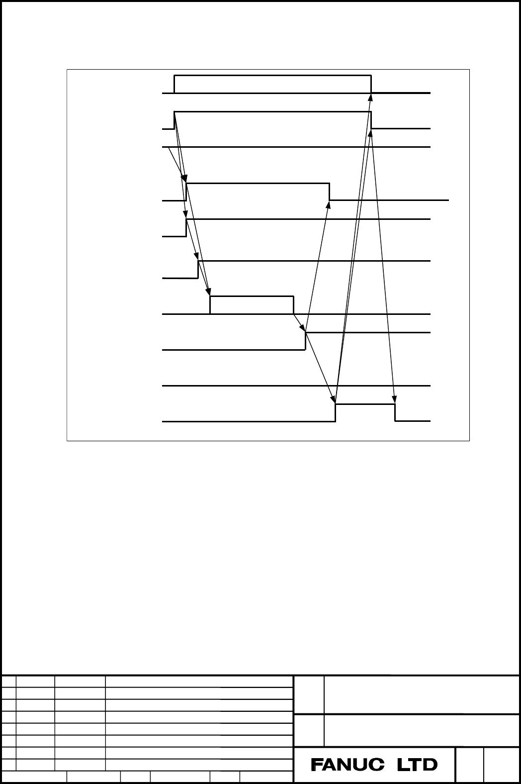
Example) Under composite control of Cs axis in two-path system
(1) Excute M code on path-1. Then, MF signal <F0007.0> is set to 1.
(2) Check that Cs axis zero point establishment state signal on path-2
CSPENA <F1048.4> is 1. And, Set both Cs axis coordinate
establishment request signal on path-2 CSFI1<G1274.4> and spindle
contour control change signal on path-2 CON<G1027.7> to 1.
(3) Absolute coordinate on path-1, relative coordinate on path-1, and
machine coordinate on path-2 are counted up.
(4) After complete of count up, reference point establishment signal on
path-2 ZRFx<F0120> is set to 1. So, set Cs axis coordinate
establishment request signal on path-2 CSFI1<G1274.4> to 0.
(5) Excute FIN sequence for M code on path-1.
CSFOx<F1274.4-7>
Count up coordinate
M code for Cs contor
control <F010 - 013>
FIN<G0004.3>
MF<F0007.0>
M code
CSFIx<G1274.4-7>
CSPENA<F1048.4>
ZRFx<F1120>
FSCSL<F1044.1>
CON<G1027.7>
Contents Summary of FANUC Series 30i/31i/32i/-MODEL A Cs Contour Control Axis Coordinate Establishment, Specifications Additional Manual
- Page 1FANUC Series 30i/31i/32i-MODEL A Cs contour control axis coordinate establishment Specifications FANUC Series 30i/31i/32i/-MODEL A Title Cs contour control axis coordinate establishment Draw A-79613E No. Ed. Date Design Description Page 1/11 Date June.02.’04 Design. Apprv.
- Page 2Outline Generally, position is lost just after changing serial spindle mode from speed control mode to Cs contour control mode. This function makes it possible to establish position without reference point return by setting Cs axis coordinate establishment request signal CSFIx
to 1. Note - Page 3In case of failure to establish Cs axis coordinate When Cs axis coordinate establishment is failed, PS alarm 5346 occurs on the path that counts up absolute coordinate (work coordinate). Causes of Cs axis coordinate establishment failure are as follows. - Cs axis zero point establishment state signa
- Page 4Sequence(Time Chart) In case that Cs axis coordinate establishment is completed correctly. M code for Cs contour M code control
CSPENA CSFIx CON or CONSx FSCSL or FCSSx Count up coordinate ZRFx CSFOx FIN< - Page 5In cast that Cs axis coordinate establishment is failed. M code for Cs contour M code control
MF CSPENA CSFIx CON or CONSx FSCSL or FCSSx Abort Count up coordinate ZRFx CSFOx FIN When coordinate est - Page 6Example) Under composite control of Cs axis in two-path system M code for Cs contor M code control
MF CSPENA CSFIx CON FSCSL Count up coordinate ZRFx CSFOx FIN (1) Excute M code on path-1. Then, MF signal - Page 7Note CMR Set the same value of CMR( parameter No.1820) for all Cs axes to establish their coordinate in composite control. If value of CMR are different, coordinate establishment is not completed correctly. Feed axis synchronization control Feed axis synchronization control is not available under Cs
- Page 8Signals Cs axis coordinate establishment request signals CSFI1 - CSFI4
[Classification] Input signal [Function] Execute Cs axis coordinate establishment [Operation] When CSFIx is 1 in Cs contour control mode, absolute coordinate and machine coordinate are established according to Cs axis - Page 9Signal Address #7 #6 #5 #4 #3 #2 #1 #0 Gn274 CSFI4 CSFI3 CSFI2 CSFI1 #7 #6 #5 #4 #3 #2 #1 #0 Fn048 CSPENA #7 #6 #5 #4 #3 #2 #1 #0 Fn052 CSPENB #7 #6 #5 #4 #3 #2 #1 #0 Fn171 CSPENC #7 #6 #5 #4 #3 #2 #1 #0 Fn269 CSPEND #7 #6 #5 #4 #3 #2 #1 #0 Fn274 CSFO4 CSFO3 CSFO2 CSFO1 FANUC Series 30i/31i/32i/-MOD
- Page 10Parameter #7 #6 #5 #4 #3 #2 #1 #0 1005 ZRN [Data type] Bit axis ZRNx When a command specifying the movement except for G28 is issued in automatic operation (MEM or MDI) and when a return to the reference position has not been performed since the power was turned on 0: An alarm is generated (PS alarm
- Page 11Alarm and message Number Message Description PS5346 RETURN TO REFERENCE Cs coordinate establishment was aborted. POINT Perform manual reference point return of Cs axis. 1. CSFIx was set to 1 when Cs axis zero point establishment state signal CSPENx is 0. 2. Position data was not transferred from spi