Twin Table Control Function Specification Additional Manual Page 6
Additional Manual
6/7
EDT. DATE
DESIG.
DESCRIPTION
TITLE
NO.
FANUC Series 16i/18i-MA
Twin table control function
Specifications
A-60920EN/02
PAGE
02
01
11/20/03
07/11/97
Partly modified
Newly registered
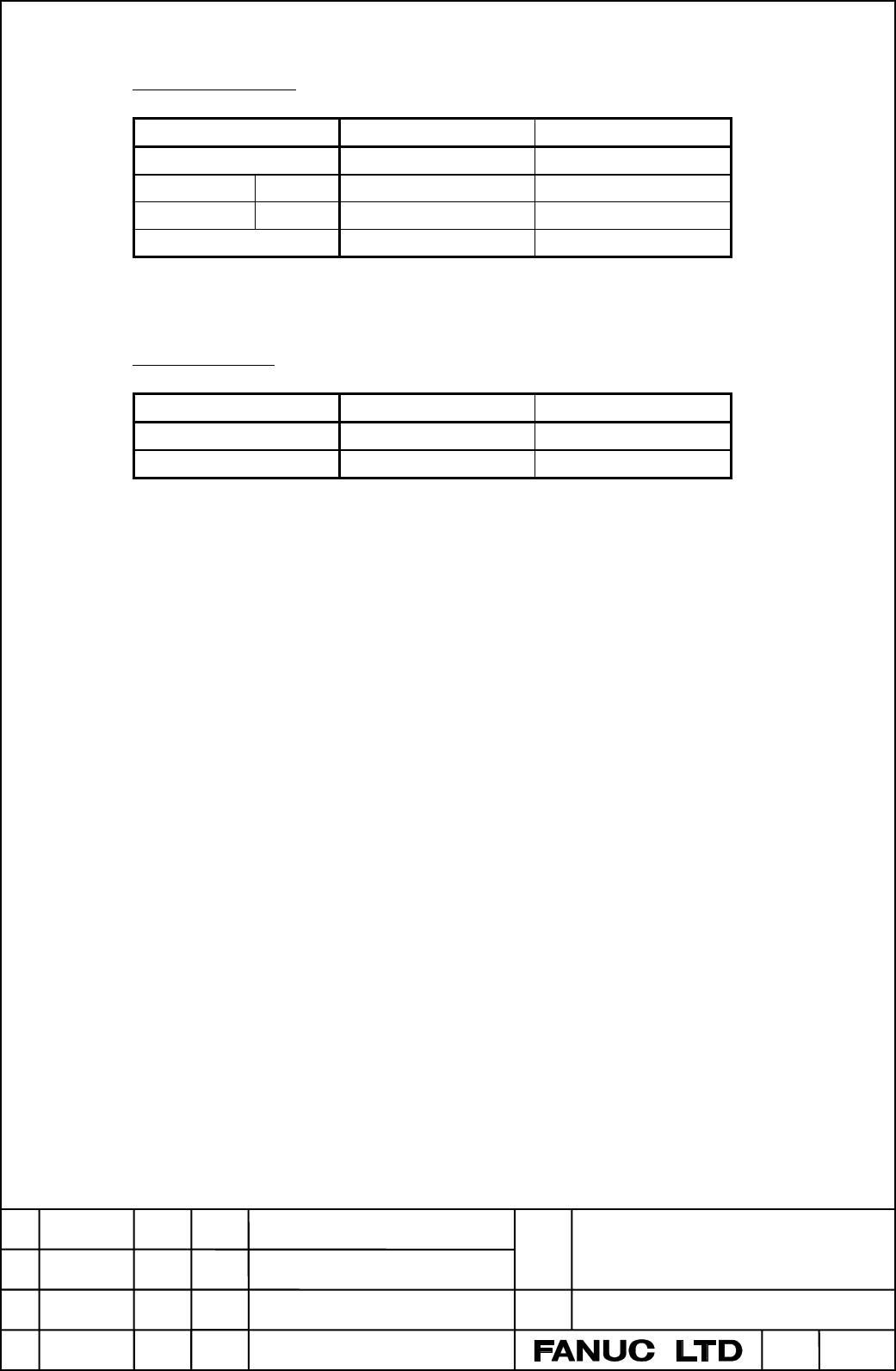
Automatic operation
Mode SYNM*(G122) SYNC*(G138)
Synchronous operation 1 1
Independent Slave 0 1
operation Master
*1
0 0
Normal operation 0 0
*1:The case of that the master axis moves independently in independent operation mode
is the same as that in normal operation mode.
Manual operation
Mode SYNMJ*(G128) SYNCJ*(G140)
Synchronous operation 1 1
Normal operation 0 0
Note) Independent operation mode does not exist in manual operation.
5. Notice
(1) The twin table control function is an optional function.
(2) The limitations of the synchronous operation are the same as the simple synchronous
control.
(3) It is recommended to specify the command for automatic return to the reference position
(G28) or second, third, fourth reference position return (G30) in the normal operation mode.
(4) Keep the manual absolute switch on (ABS=1) during the synchronous operation. If it is off,
movement along the slave axis may not be correctly controlled.
(5) If the command for changing the mode to the independent operation is issued, it will not
change until the next two or three blocks including this command block. By specifying the M
code for changing the mode as a non-buffering M code, it will change the mode from the next
block. But in the case of changing to the synchronous operation mode,
(6) Set the number of the master axis to parameter No.8311 for setting of the master axes and
the slave axes. If the same numbers as the master axis were set to the parameters No.8311,
the axis of the smallest slave axis number would be available.
(7) The combinations of the master axis and the slave axis are maximum 4 pairs. If over 4 pairs
were specified, the pairs of the 4 smallest slave axis number would be available.
(8) If the parameters No.8301#0,1(SY0,SY1) are set for the synchronous control, the twin table
control can not be used. The simple synchronous control is only available in this case.
(9) In the independent operation mode of slave axes, if the command to specify the origin of the
workpiece coordinate system(G92) or of the local coordinate system(G52), the work piece
coordinate of slave axis is set. But if the parameter No.8305#6 TTSLB is set to 1, the one of
master axis is set.
(10) In the synchronous mode, the signals (external deceleration, interlock, and machine lock
Contents Summary of Twin Table Control Function Specification Additional Manual
- Page 1FANUC Series 16i/18i-MA Twin table control function Specifications 《Contents》 1. Overview .........................................................................................................................2 2. Details ............................................................................
- Page 21. Overview The input signal sent from the machine can switch the operation mode of two or more specified axes: Synchronous, independent, or normal operation. 2. Details 2.1 Twin table control When a machine has two tables that are independently driven with different control axes, the following oper
- Page 3(3) Normal operation This mode is used to machine different workpieces on different tables. As in usual CNC operation, movements along the master and slave axes are specified by individual axis addresses, Y and V. The movements along the master and slave axes can be specified in an identical block.
- Page 42.6 Notice of the independent operation The Chamfering/Corner R function can be used on the slave axis in independent operation. If the parameter No.8305#6(TTSLB)=1, setting of signals can be changed. The content of changing is the followings. TTSLB = 0 TTSLB = 1 Chamfering/Corner R Available Availa
- Page 53. Parameter 8311 Number of the master axis for twin table control Data type: Byte axis Valid data range: 1,2,3,...,number of controlled axes Set the number of the master axis at this parameter of the slave axis for twin table control. Value data are expressed like follows: 1 means the 1st axis, 2 m
- Page 6Automatic operation Mode SYNM*(G122) SYNC*(G138) Synchronous operation 1 1 Independent Slave 0 1 operation Master*1 0 0 Normal operation 0 0 *1:The case of that the master axis moves independently in independent operation mode is the same as that in normal operation mode. Manual operation Mode SYNMJ
- Page 7etc.) are available on master axis, and the signals of slave axis are ignored. In the independent mode (slave axis), the signals of master axis are ignored, and the signals of slave axis are available. But when the parameter No.8305#6 is set to 1, the signals of slave axis are ignored, and the signa