FANUC Pulse Input Type Digital Servo Adapter, Connection Manual (Hardware) Additional Manual Page 16
Additional Manual
Dra
w
No.
Title
SheetDescri
p
tionDesi
g
n Date Edit
FANUC Pulse Input Type
Digital Servo Adapter
Connection Manual (Hardware)
A-77226EN
/ 16
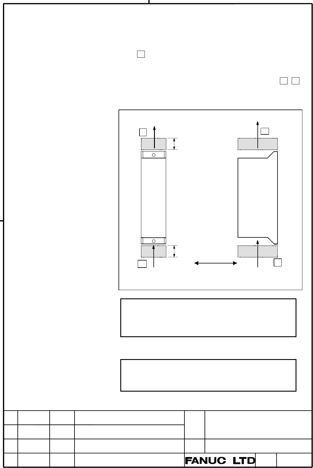
The control unit consists of a plastic box, fan motors and a PCB. A fan is
provided at the top of the control unit. The fan unit incorporates a fan
motor.
To enable easy removal and replacement of the fan unit, leave the space
(space 1 ) shown in the figure below.
The air comes into the control unit from the bottom and goes out through
the fan motor, which is located on the top of the control unit. Space as
shown in Fig. 3.8.2 must be reserved not to disturb the air flow ( 1 , 2 )
To use analog output function, allow a space large enough (at least about
80 mm wide) to attach and detach its cable at the bottom of the unit.
50mm or more
(80mm)
50mm or more
A
ir flow
1
1
2
Sufficient space for
replacing a printed circuit
board is required.
2
IMPORTANT
Above the control unit, leave sufficient space (50 mm or greater) to
enable easy removal and replacement of the fan unit.
If the fan unit cannot be removed, the fan cannot be replaced. Nor can
be the fuse and the printed circuit board replaced.
Warning message "FAN" is displayed on DPL/MDI, when either
of two fans stop.
NOTE
IF DPL/MDI Unit is not connected always, the host controller must
detect stoppage of fan and urge exchange of fan by displaying warning
message.
Contents Summary of FANUC Pulse Input Type Digital Servo Adapter, Connection Manual (Hardware) Additional Manual
- Page 1FANUC Pulse input type Digital servo adaptor CONNECTION MANUAL (Hardware) FANUC Pulse Input Type Title Digital Servo Adapter Connection Manual (Hardware) 01 05.06.30 Kuwahata First edition Draw A-77226EN No. Edit Date Design Description Sheet 1 / 71
- Page 2Table of Contents 1 PREFACE .................................................................................................................................. 4 2 INSTALLATION ......................................................................................................................... 5
- Page 36 CONNECTION OF I/O UNITS TO MACHINE INTERFACE..................................................... 38 6.1 OUTLINE .............................................................................................................................. 38 6.2 SIGNALS ...........................................
- Page 41 PREFACE This manual describes the electrical and structural specifications required for connecting the FANUC pulse input type Digital Servo Adapter to a machine. The models covered by this manual, and their abbreviations, are : Product Name Abbreviations FANUC Pulse input type Digital servo adapte
- Page 52 INSTALLATION 2.1 ENVIRONMENTAL REQUIREMENTS The peripheral units and the control unit have been designed on the assumption that they are housed in closed cabinets. In this manual "cabinet" refers to the following: In operation 0`C to 55`C Ambient Temperature In store or -20`C to 60`C transportatio
- Page 62.3 ACTION AGAINST NOISE The PDSA has been steadily reduced in size using surface-mount and custom LSI technologies for electronic components. The PDSA also is designed to be protected from external noise. However, it is difficult to measure the level and frequency of noise quantitatively, and noise
- Page 7NOTE 1. The groups must be 10 cm or more apart from one another when binding the cables in each group. 2. The electromagnetic shield refers to shielding between groups with grounded steel plates. FANUC Pulse Input Type Title Digital Servo Adapter Connection Manual (Hardware) Draw A-77226EN No. Edit
- Page 82.4 Ground The following ground systems are provided for the machine: (1) Signal grounding Signal grounding supplies a reference potential (0 V) for electrical signals. (2) Grounding for protection Grounding for protection is performed for safety reasons as well as to shield against external and int
- Page 92.4.1 Connecting the Ground for Signal of the Control Unit Connect the signal ground (FG) terminal for the PDSA to the grounded plate of the cabinet. The grounded plate must be connected to the protection ground (PE) as shown below. CAUTION Use the Faston terminals (A02B-0166-K330) for the frame gro
- Page 102.4.2 Noise Suppressor The AC/DC solenoid and relay are used in the power magnetics cabinet. A high pulse voltage is caused by coil inductance when these devices are turned on or off. This pulse voltage induced through the cable causes the electronic circuits to be disturbed. In general, to reduce t
- Page 11Diode Diode (used for direct-current circuits) - Diode + Use a diode which can withstand a voltage up to two times the applied voltage and a current up to two times DC relay the applied current. 2.4.3 Cable Clamp and Shield Processing If a cable connected to the PDSA, servo amplifier, spindle amplif
- Page 12Machine side installation board Control unit Ground plate Metal fittings for clamp Shield cover Cable clamp (2) Prepare ground plate like the following figure. Ground terminal (grounded) Hole for securing metal fitting clamp Mount screw hole Ground plate For the ground plate, use a metal plate of 2
- Page 13Ground plate 8mm 12mm 20mm Ground plate holes (Reference) Outer drawing of metal fittings for clamp max. 55mm 28mm 6 mm 17mm Outer drawings of metal fittings for clamp Ordering specification for metal fittings for clamp A02B-0124-K001 (8 pieces) FANUC Pulse Input Type Title Digital Servo Adapter Con
- Page 142.5 CONTROL UNIT 2.5.1 Configuration of the Control Unit The control units of the PDSA consist of below components. No. Name Remarks 1 Control unit 2 Fan unit FANUC Pulse Input Type Title Digital Servo Adapter Connection Manual (Hardware) Draw A-77226EN No. Edit Date Design Description Sheet 14 /
- Page 152.5.2 Installation of the Control Unit Space between control units to be installed FANUC Pulse Input Type Title Digital Servo Adapter Connection Manual (Hardware) Draw A-77226EN No. Edit Date Design Description Sheet 15 /
- Page 16The control unit consists of a plastic box, fan motors and a PCB. A fan is provided at the top of the control unit. The fan unit incorporates a fan motor. To enable easy removal and replacement of the fan unit, leave the space (space 1 ) shown in the figure below. The air comes into the control unit
- Page 172.6 CABLE-LEAD-IN DIAGRAM FANUC Pulse Input Type Title Digital Servo Adapter Connection Manual (Hardware) Draw A-77226EN No. Edit Date Design Description Sheet 17 /
- Page 182.7 CONNECTOR LAYOUT OF CONTROL UNIT Front Bottom face BAT1 BATTERY JA70A Analog output JA69A PULSE input/output JA69B PULSE input/output CNM1B JA69C PULSE input/output MEMORY CARD JA69D PULSE input/output JD40 RS-422 JA70B Analog output JD42 RS-232-C LEDM2 FUSE diagnose display LED Left CP2 DC 24V
- Page 193 TOTAL CONNECTION Base PCB 24V-IN(CP1) DC24V Power supply unit 24V-PUT(CP2) Host controller PULSE IN/OUT(JA69 PULSE IN/OUT(JA69 PULSE IN/OUT(JA69 PULSE IN/OUT(JA69 DPL/MDI RS-422(JD40) RS-232-C(JD42) Operator's panel Built-in I/O(CB155) Built-in I/O(CB156) FANUC Pulse Input Type Title Digital Servo
- Page 20TB2 CX2A JX1A FSSB (COP10A) COP10B 1st axis SVM TB2 servo COP10A JF1 motor TB1 CX2B JX1B COP10B SVM 2nd axis servo COP10A motor COP10B SVM 3rd axis servo COP10A motor COP10B SVM 4th axis servo COP10A motor ~ 8th axis servo motor Analog output (JA70A) Analog output Analog output (JA70B) Analog output
- Page 214 POWER SUPPLY UNIT CONNECTION 4.1 Details of 24 VDC For the controller of the PDSA, use a regulated power supply satisfying the following conditions. 24 VDC±10% (including an instantaneous and ripple value) 1) Main unit power supply - Control power supply: 1.5A 2) The requirements of UL 1950 standa
- Page 224.3 POWER CONNECTIION DIAGRAMS OF SYSTEMS Main Electromagnetic AC line Servo Servo breaker contacts filter converter inverter 3-phase 200 VAC for motive 200VAC power DC24V Single-phase 入力 200 VAC for control External 24-VDC 24-VDC PDSA input power source DC24V The power to separate detectors (scales
- Page 234.4 POWER-ON SEQUENCE Apply the following power-on sequence. Alternatively, turn on the power to all the units simultaneously. 1 Power to the entire machine <200 VAC> Power to the servo amplifier <200 VAC> 2 Power to the host controller 3 Power to the PDSA<24 VAC> "Simultaneously," as used here, ref
- Page 244.5 POWER-OFF SEQUENCE Apply the following power-off sequence. Alternatively, turn off the power to all the units simultaneously. 1 Power to the PDSA<24 VAC> 2 Power to the host controller Power to the servo amplifier <200 VAC> 3 Power to the entire machine <200 VAC> "Simultaneously," as used here,
- Page 254.7 BATTERY FOR MEMORY BACKUP(3 VDC) System parameters are stored in SRAM memory in the PDSA. The power to the SRAM memory is backed up by lithium battery mounted on the front panel of the PDSA. If the battery is connected correctly, the data above is not lost when the main power is turned off. The
- Page 26WARNING Using other than the recommended battery may result in the battery exploding. Replace the battery only with the specified battery (A02B-0200-K102). Battery latch Battery connector Lithium battery CAUTION 1. Before replacing the battery, check that the latest data of the SRAM memory is alread
- Page 275 CONNECTION TO HOST CONTROLLOR 5.1 Command Pulse Input Interface Can give position command by pulses. Pulse type can be selected by a parameter among A and B phase, CW/CCW and Sign + pulse. Host FANUC Pulse input type controller Digital servo adaptor A and B phase CW/CCW Sign+pulse FANUC Pulse Inpu
- Page 285.1.1 Operation conditions of A and B phase pulse I/F The maximum allowable frequency for the input signal is 500kpps. (The frequency is, however, multiplied by four in the PDSA.) - Pulses for positive-direction move command PA *PA PB *PB Tp Tp Tp Tp Tp: 0.4 µs or more Tcy Tcyc: 2.0 µs or more c - P
- Page 295.1.2 Operating conditions of Sign + pulse I/F The maximum allowable frequency for the input signal is 2 Mpps. Positive-direction move command Negative-direction move command Sign Pulse Ta Tp Tp Ta Ta Ta Tp :0.2µsec or more Tcyc Ta :0.5µsec or more Tcyc:0.5µsec or more Sign *Sign Positive-direction
- Page 305.1.3 Operation condition of CCW/CW pulse I/F The maximum allowable frequency for the input signal is 2 Mpps. Positive-direction move command Negative-direction move command CCW Tp Tp Tcyc CW Ta Tp Tp Ta Tp :0.2µsec or more Ta :0.5µsec or more Tcyc Tcyc:0.5µsec or more Sequence Pulse for positive- P
- Page 315.1.4 Specification of input signal - Feedback pulse interface of PDSA is adapted for the differential line driver. (adaptable differential line driver: SN75113 or its compatibles) Voltage condition HOST PDSA CONTROLLER NOTE P Vd Voltage of VP and V*P that described in right figure must be satisfied
- Page 325.2 Details of connection 5.2.1 A and B phase Pulse I/F HOST CONTROLLER PDSA JA69A, B, C, D PA ( 1) PAIn *PA ( 2) *PAIn PB ( 3) PBIn *PB ( 4) *PBIn 0V ( 5) 0V 0V ( 6) 0V PA (11) PAIn+1 *PA (12) *PAIn+1 PB (13) PBIn+1 *PB (14) *PBIn+1 0V (15) 0V 0V (16) 0V JA69A: n=1 Connector:PCR-E20FS(Soldering typ
- Page 335.2.2 Sign + Pulse I/F HOST CONTROLLER PDSA JA69A,B,C,D SIGN ( 1) SIGN n *SIGN ( 2) *SIGN n PULSE ( 3) PULSE n *PULSE ( 4) *PULSE n 0V ( 5) 0V 0V ( 6) 0V SIGN (11) SIGN n+1 *SIGN (12) *SIGN n+1 PULSE (13) PULSE n+1 *PULSE (14) *PULSE n+1 0V (15) 0V 0V (16) 0V JA69A: n=1 Connector:PCR-E20FS(Soldering
- Page 345.2.3 CCW/CW Pulse I/F HOST CONTROLLER PDSA JA69A,B,C,D CCW ( 1) CCW n *CCW ( 2) *CCW n CW ( 3) CW n *CW ( 4) *CW n 0V ( 5) 0V 0V ( 6) 0V CCW (11) CCW n+1 *CCW (12) *CCW n+1 CW (13) CW n+1 *CCW (14) *CCW n+1 0V (15) 0V 0V (16) 0V JA69A: n=1 Connector:PCR-E20FS(Soldering type) JA69B: n=3 or PCR-E20FA
- Page 355.3 Feedback Pulse Output I/F Output feedback pulse is A and B phase pulse. Z phase is not supported. Host Controller FANUC Pulse input type Digital Servo Adapter A and B phase pulse FANUC Pulse Input Type Title Digital Servo Adapter Connection Manual (Hardware) Draw A-77226EN No. Edit Date Design D
- Page 365.3.1 Signal Specification Timing - Movement in the positive direction PA *PA PB *PB Tp Tp Tp Tp Tp: 0.5µsec Tcyc Tcyc: 2.0µsec - Movement in the negative direction PA *PA PB *PB Tp Tp Tp Tp Tp: 0.5 µsec Tcyc Tcyc: 2.0µsec - Relation of feedback pulse and encoder's output Internal counter of PDSA sa
- Page 375.4 Details of Cable PDSA HOST CONTROLLER JA69A, B, C, PAO n ( 7) PA *PAO n ( 8) *PA PBO n ( 9) PB *PBO n (10) *PB 0V ( 5) 0V 0V ( 6) 0V PAO n+1 (17) PA *PAO n+1 (18) *PA PBO n+1 (19) PB *PBO n+1 (20) *PB 0V(15) 0V 0V(16) 0V JA69A: n=1 Connector:PCR-E20FS(Soldering type) JA69B: n=3 or PCR-E20FA(IDC
- Page 386 CONNECTION OF I/O UNITS TO MACHINE INTERFACE 6.1 OUTLINE Built-in I/O is I/O that mounted on the base PC board of PDSA. The DO signals are source type and conform to the safety requirements. This built-in I/O is designed such that a connector panel is used to relay the signals between the I/O card
- Page 39(5) When the cable is run outside the cabinet, use a common shield cable. For the cable use a bundled sealed cable 34 pin cable with shield (soldering type) OKI DENSEN CO,.LTD SFX-S 34-7/0.127 3030-SV(20266)K FANUC Specification A66L-0001-0308#S34S Clamp the cable shield with the cable clamp on the
- Page 406.2 SIGNALS 6.2.1 DI signals 1) DC input signal A DC input signal A is a category of signals sent from machine components (such as pushbutton, limit switch, relay contact) to the PDSA. 2) DC input signal B DC input signal B is a category of signals sent from the machine to the PDSA for high-speed op
- Page 416.2.2 Output Signal Requirement The PDSA uses source-type output signals that comply with safety standards. The output signals are rated as follows: Maximum load current with the driver turned on: 200 mA (including an instantaneous value and ripple) Saturation voltage with the driver turned on: 1.0
- Page 426.3 Signal list (1) DI signals (from Host controller to PDSA) Address #7 #6 #5 #4 #3 #2 #1 #0 X1000 ERS - - *ESP ZRN - - - SVF8/ SVF7/ SVF6/ SVF5/ SVF4/ SVF3/ SVF2/ SVF1/ X1001 TRQE8 TRQE7 TRQE6 TRQE5 TRQE4 TRQE3 TRQE2 TRQE1 X1002 PRDY8 PRDY7 PRDY6 PRDY5 PRDY4 PRDY3 PRDY2 PRDY1 X1003 PLSC8 PLSC7 PLS
- Page 436.4 Machine Interface Built-in I/O CB155 CB156 34-pin flat cable connector A B A B 01 +24E +24E 01 +24E +24E 02 (Reserved) (Reserved) 02 PRDY1 PRDY2 03 (Reserved) ZRN 03 PRDY3 PRDY4 04 *ESP (Reserved) 04 PRDY5 PRDY6 05 ERS 05 PRDY7 PRDY8 06 (Reserved) DOC 06 DOC DOC 07 SVF1/TRQE1 SVF1/TRQE2 07 PLSC1
- Page 446.5 Details of DI Connection PDSA Example of connection Pin number +24E CB155(A01, B01) Bit number Address number Filter and level conversion circuit (Reserved) CB155(A02) X1000. 0 (Reserved) CB155(B02) X1000. 1 (Reserved) CB155(A03) X1000. 2 ZRN CB155(B03) X1000. 3 *ESP CB155(A04) X1000. 4 (Reserve
- Page 45PDSA Example of connection Pin number +24E CB155(A01, B01) Bit number Address number Filter and level SVF1/ conversion circuit TRQE1 CB155(A07) X1001. 0 SVF2/ TRQE2 CB155(B07) X1001. 1 SVF3/ TRQE3 CB155(A08) X1001. 2 SVF4/ TRQE4 CB155(B08) X1001. 3 SVF5/ TRQE5 CB155(A09) X1001. 4 SVF6/ TRQE6 CB155(B
- Page 46PDSA Example of connection Pin number +24E CB156(A01, B01) Bit number Address number Filter and level conversion circuit PRDY1 CB156(A02) X1002. 0 PRDY2 CB156(B02) X1002. 1 PRDY3 CB156(A03) X1002. 2 PRDY4 CB156(B03) X1002. 3 PRDY5 CB156(A04) X1002. 4 PRDY6 CB156(B04) X1002. 5 PRDY7 CB156(A05) X1002.
- Page 47PDSA Example ob connection Pin number +24E CB156(A01, B01) Bit number Address number Filter and level conversion circuit PLSC1 CB156(A07) X1003. 0 PLSC2 CB156(B07) X1003. 1 PLSC3 CB156(A08) X1003. 2 PLSC4 CB156(B08) X1003. 3 PLSC5 CB156(A09) X1003. 4 PLSC6 CB156(B09) X1003. 5 PLSC7 CB156(A10) X1003.
- Page 486.6 Details of DO Connection PDSA Pin number Example of connection Source-type Bit number driver CB155(B06) Address number CB156(A06, B06) Regulated DOC Power supply 24V 0V Y1000. 0 CB155(A11) AL/NAL Y1000. 1 CB155(B11) RST Y1000. 2 CB155(A12) BAL Y1000. 3 CB155(B12) ZRNO Y1000. 4 CB155(A13) (Reserv
- Page 49PDSA Pin number Example of connection Source-type Bit number driver CB155(B06) Address number CB156(A06, B06) DOC Regulated Power supply 24V 0V Y1001. 0 INP1/ CB155(A15) ZP1 INP2/ Y1001. 1 CB155(B15) ZP2 INP3/ Y1001. 2 CB155(A16) ZP3 INP4/ Y1001. 3 ZP4 CB155(B16) INP5/ Y1001. 4 CB156(A15) ZP5 INP6/
- Page 50PDSA Pin number Example of connection Source-type Bit number driver CB155(B06) Address number CB156(A06, B06) DOC Regulated Power supply 24V 0V Y1002. 0 CB156(A11) VRD1 Y1002. 1 CB156(B11) VRD2 Y1002. 2 CB156(A12) VRD3 Y1002. 3 CB156(B12) VRD4 VRD5 Y1002. 4 CB156(A13) Y1002. 5 CB156(B13) VRD6 Y1002.
- Page 517 CONNECTION TO PERIPHERALS 7.1 SERVO INTERFACE (FSSB) 7.1.1 Connection by FSSB The connection between the PDSA and the servo amplifiers should use only one optical cable, regardless of the number of controlled axes. For the connection of the servo amplifier, refer to Descriptions of servo amplifier
- Page 527.2 SEPARATE DETECTOR INTERFACE UNIT 7.2.1 General When a separate pulse coder or linear scale is used, a separate detector interface unit is required. The separate detector interface unit should bi connected to the PDSA through an optical cable, as one of the units on the servo interface (FSSB). Se
- Page 537.2.2 Connection of Power supply Power of the separate detector interface unit should be supplied from an external 24 VDC power supply. To the extended unit, if it exists, power is supplied from the basic unit. Separate detector interface unit (basic) External power supply CP11A 1 +24V 24 VDC regula
- Page 547.2.3 Connection to Linear Scale (Parallel Interface) NOTE 1 The +5V output in the interface can be used as the power supply of a separate detector or linear scale. The supply current per separate detector is 0.35 A maximum. The voltage of the basic unit is 4.95 V (min), and that of the additional u
- Page 557.2.4 Connection to Separate Pulse Coder (Parallel Interface) NOTE 1 The +5V output in the interface can be used as the power supply of a separate detector or linear scale. The supply current per separate detector is 0.35 A maximum. The voltage of the basic unit is 4.95 V (min), and that of the addi
- Page 567.2.5 Input Signal Requirements The standard of the feedback signal from the separate detector is as shown below. (1) A and B phase signal input This is a method to input position information by the mutual 90 degree phase slip of A and B phase signals. Detection of the position is performed with the
- Page 57(3) Z phase signal input For the Z phase signal (1 rotation signal), a signal width of more than 1 frequency of the A phase or B phase signals is necessary. Input voltage requirements The voltage of A and B phase signals must meet the following requirements. High level: 2.4V or more Low level: 0.8V
- Page 587.2.6 Connection between Basic and Additional Units An additional unit must be connected to a basic unit with a flat cable, as shown below. The flat cable is 100 mm in length. Order a flat cable together with a separate detector interface unit. FANUC Pulse Input Type Title Digital Servo Adapter Conn
- Page 597.2.7 Outside Dimensions FANUC Pulse Input Type Title Digital Servo Adapter Connection Manual (Hardware) Draw A-77226EN No. Edit Date Design Description Sheet 59 /
- Page 607.2.8 Connector Positions Positions of the connectors of a basic unit Positions of the connectors of an additional unit FANUC Pulse Input Type Title Digital Servo Adapter Connection Manual (Hardware) Draw A-77226EN No. Edit Date Design Description Sheet 60 /
- Page 617.2.9 Installation 1) Notes on installation (1) Use the unit inside a hermetically sealed cabinet. (2) Mount the unit on a vertical face. Leave a space of 100 mm or greater both above and below the unit. Do not place a device that generates large amounts of heat below the unit. (3) When using basic
- Page 627.2.10 Notes on Installing a Separate Detector Interface Unit CAUTION To install/remove the unit, a screwdriver must be inserted obliquely. So, sufficient access clearances are required on both sides of the unit. As a guideline, if the front of an adjacent unit appears flush with the unit or slightl
- Page 63Installing the unit on the DIN rail Installing the unit: 1. Hook the unit on the top of the DIN rail. 2. Push the unit in until it clicks. Removing the unit: 1. Push down the lock by using a screwdriver. 2. Remove the unit by pulling the lower end of the unit towards you. CAUTION When removing the u
- Page 647.3 ANALOG OUTPUT (option) 7.3.1 OUTLINE The PDSA has analog data output function. Option card is required to enable the analog data output function. 7.3.2 SPECIFICATION Item Specification Number of output 4/8/12/16channels channels (number of output channels are due to option card) Analog Output -1
- Page 657.3.3 Details of Cable 7.3.3.1 1st - 4th channels output PDSA JA70A AO1+ (1) External load AO1- (2) AO2+ (7) External load AO2- (8) AO3+ (12) External load AO3- (11) AO4+ (18) External load AO4- (17) Hirose electric CO., LTD Connector : FI40B-20S (Soldering type) Housing : FI-20-CV5 (Plastic case) N
- Page 667.3.3.2 5th - 8th channels output PDSA JA70B AO5+ (1) External load AO5- (2) AO6+ (7) External load AO6- (8) AO7+ (12) External load AO7- (11) AO8+ (18) External load AO8- (17) Hirose electric CO., LTD Connector : FI40B-20S(Soldering type) Housing : FI-20-CV5(Plastic case) NOTICE 1 Be sure to connec
- Page 677.3.3.3 9th - 12th channels output PDSA JA70A AO9+ (3) External load AO9- (4) AO10+ (9) External load AO10- (10) AO11+ (14) External load AO11- (13) AO12+ (20) External load AO12- (19) Hirose electric CO., LTD Connector :FI40B-20S (Soldering type) Housing :FI-20-CV5 (Plastic case) NOTICE 1 Be sure t
- Page 687.3.3.4 13th - 16th channels output PDSA JA70B AO13+ (3) External load AO13- (4) AO14+ (9) External load AO14- (10) AO15+ (14) External load AO15- (13) AO16+ (20) External load AO16- (19) Hirose electric CO., LTD Connector :FI40B-20S (Soldering type) Housing :FI-20-CV5 (Plastic case) NOTICE 1 Be sur
- Page 698 EMERGENCY STOP SIGNAL 8.1 GENERAL Using the emergency stop signal effectively enables the design of safe machines The emergency stop signal is provided to bring a machine to an emergency stop. It must be input to the PDSA and servo amplifier. An emergency stop signal is usually generated by closin
- Page 708.3 SERVO Shutting off the servo amplifier power causes a dynamic brake to be applied to the servo motor. Even when a dynamic brake is applied, however, a servo motor attached to a vertical axis can move under the force of gravity. To overcome this problem, use a servo motor with a brake. The FANUC
- Page 71Brake control at emergency stop Emergency stop signal The emergency stop signal is controlled as an input signal for the PDSA (*ESP) and as an input to the power supply module (PSM) that directly shut off the motor driving power. Brake control When an emergency stop is performed, brake control is pe