FANUC Servo Amplifier ßi Series I/O Link Option Modification from I/O Link ß Additional Manual Page 7
Additional Manual
FANUC SERVO AMPLIFIER βi series I/O Link Option
Modification from I/O Link β
EDIT
DRAW. NO. CUST
TITLE
DESCRIPTION
DESIG.
DATE
A-79487E
7
/
23
01
04.03.15
SHEET
Newly designed
Ⅰ START-UP PROCEDURE
4 OPERATION CHECK METHOD
4.1 CHECK PROCEDURE
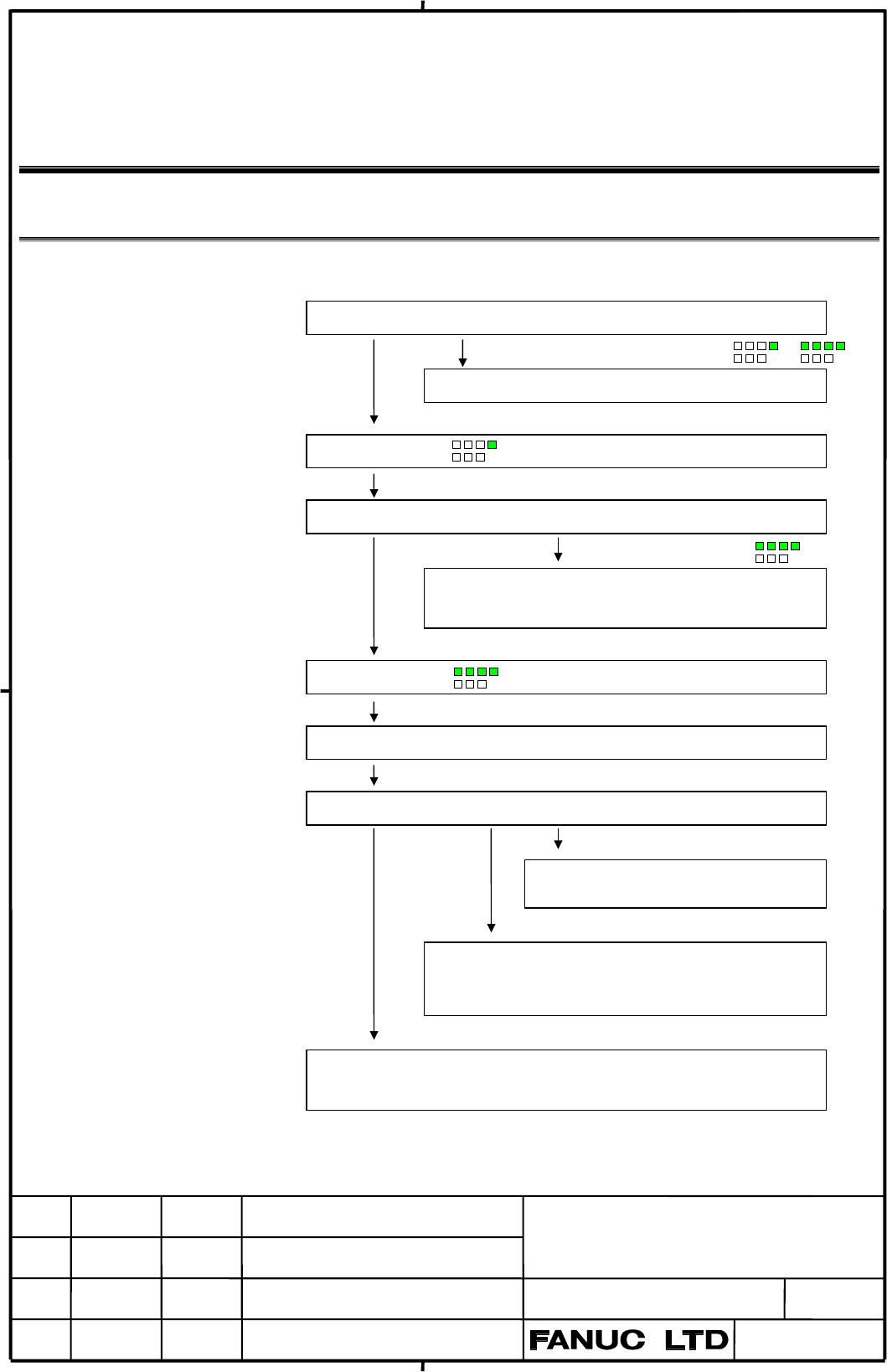
1. Turn on the power.
When the LED indicates data other than or
Refer to the explanation of troubleshooting in Part III.
2. The LED indicates
3. The emergency stop state is released.
The LED does not indicate
Check the *ESP signal applied to the servo amplifier unit.
Check the *ESP signal applied through the I/O link.
4. The LED indicates
5. Issue a command from the host controller.
6. Check the operation of the servo motor.
An alarm is issued.
Refer to the explanation of troubleshooting in
Part III.
The motor does not rotate.
Check the command.
Check the parameter settings.
Check *RILK applied to the servo amplifier unit.
The motor malfunctions.
Check the standard setting parameters are correctly set. Check the setting value
of No.100(load inertia) and No.107(position loop gain).
Contents Summary of FANUC Servo Amplifier ßi Series I/O Link Option Modification from I/O Link ß Additional Manual
- Page 1FANUC SERVO AMPLIFIER βi series I/O Link Option Modification from I/O Link β 1 OUTLINE............................................................................................................................. 2 2 DETAILED DESCRIPTION................................................................
- Page 21 OUTLINE This technical report explains the modification from “FANUC SERVO MOTOR β series I/O Link Option” (for short, “I/O Link β”) to “FANUC SERVO AMPLIFIER βi series I/O Link Option” (for short, “I/O Link βi ”). About the contents except this technical report, please refer to “FANUC SERVO MOTOR
- Page 3Ⅰ START-UP PROCEDURE 3 START-UP PROCEDURE 3.4 PARAMETER INITIALIZATION (1) Preparation prior to servo parameter initialization Before servo parameter initialization, check the following information: 1. Servo motor model (Example: β 8/3000is) 2. Amount of travel per motor revolution (Example: 10 mm/m
- Page 44. Set the initialization bit DGPR to 0. b7 b6 b5 b4 b3 b2 b1 b0 No.12 DGPR When this bit is set to 0, a power-down request alarm (alarm No. 0) is issued. However, following procedure from 5 to 9 can be done. Start initialization It is not necessary to turn off CNC until 11. DGPR (b1) = 0 DGPR(b1) b
- Page 56. Set CMR In parameter No.032, set coefficient for the command unit from the CNC system to the servo system. CMR = Command unit/detection unit When CMR is from 1 to 48 Setting = CMR x 2 When CMR is from 1/2 to 1/27 Setting = 1/CMR + 100 Usually, CMR = 1. So, set “2” in parameter No.032. 7. Set the
- Page 69. Set the reference counter capacity. (Parameter No. 180) Set the reference counter capacity when performing a reference position return operation based on the grid method. Set the number of position pulses per motor revolution, or set that number divided by an integer. Example: αi pulse coders, se
- Page 7Ⅰ START-UP PROCEDURE 4 OPERATION CHECK METHOD 4.1 CHECK PROCEDURE 1. Turn on the power. When the LED indicates data other than or Refer to the explanation of troubleshooting in Part III. 2. The LED indicates 3. The emergency stop state is released. The LED does not indicate Check the *ESP signal app
- Page 8Table 4.1 LED Indications and Meanings LED State Description indication This indicates that control power (+24 Servo amplifier VDC) is supplied. No alarm is issued, unit not ready but the motor is not activated. This indicates that the motor is Servo amplifier activated, and that commands can now un
- Page 9Ⅰ TROUBLESHOOTING AND COUNTERMEASURES 2 ALARM DISPLAY AND CORRESPONDING COUNTERMEASURES LED type Number Alarm type (Classification by Red LED) Or 000 to 299 Program or setting alarm 300 to 399 Pulse coder alarm Or 400 to 499 Servo alarm Same as PS alarm 500 to 599 Overtravel alarm Or - System alarm
- Page 10No. LED display Description Countermeasure The reference position has not yet Set the reference position. been established. This occurs 224 only when the ZRTN bit of parameter No.001 is set to 0. Input data 1 or command is invalid. Check input data 1, specified with 250 a function code. Input data 2
- Page 11Pulse coder alarms No. LED display Description Countermeasure A communication error (DTER) Check the continuity of the signal for the serial pulse coder was cable. If the cable is normal, the detected. pulse coder may be defective. 300 Turn the power off. If the alarm recurs when the power is reappl
- Page 12No. LED display Description Countermeasure When the absolute pulse coder is Cause the motor to rotate through used, the motor has not yet more than one turn in jog feed 319 rotated through more than one mode, then turn the power off turn after the first power-up. then back on. The battery voltage of
- Page 13Servo alarms No. LED display Description Countermeasure The servo motor has overheated. The motor operation condition may 400 (estimated value) be too severe. Check the operation condition. DRDY(Drive Ready signal) becomes 0. 401 The servo amplifier is not ready. SVM1-4i The cooling fins have The lo
- Page 14No. LED display Description Countermeasure The servo position error in the Determine the mechanical cause of stop state is larger than the value the large position error. 410 specified in parameter No.110. If no mechanical cause is found, specify a larger value for the parameter. The servo position
- Page 15No. LED display Description Countermeasure DC Link Over Voltage Alarm This alarm is issued when the DC has been issued. voltage of the main circuit power is too high. (1) When SVM1-4i or SVM1-20i is used, and a separate regenerative discharge unit is not used, check the specification to see if regen
- Page 16No. LED display Description Countermeasure Inverter IPM Alarm has been issued. (1) Check whether the cooling fan is not stopped. (2) Check whether the motor is used within related current. (3) Check whether the temperature in locker is higher. Check the fin or filter in locker. (4) Check whether the
- Page 17No. LED display Description Countermeasure DO Alarm is issued. Replace the servo amplifier unit. 418 The specified speed exceeds Re-examine the CMR and speed 423 32767000 detection units per settings. second. The cooling fan has stopped. This alarm is issued when the fan motor built into the servo a
- Page 18Overtravel alarms No. LED display Description Countermeasure The positive stroke limit has been Check whether *+OT and *-OT are 500 exceeded. connected correctly. Check whether a correct move command The negative stroke limit has been is specified. Move the tool in the 501 exceeded. opposite directi
- Page 19System alarms No. LED display Description Countermeasure An error was detected in the RAM Replace the servo amplifier unit. − write/read test at power-up. (External SRAM) A watchdog alarm 1 was issued. Turn the power off then back on. − If this alarm recurs, replace the servo amplifier unit. A watch
- Page 20No. LED display Description Countermeasure An error was detected in the Replace the servo amplifier unit. − control circuit. A alarm for the servo amplifier Replace the servo amplifier unit. unit is issued. (General illegal − instruction) A alarm for the servo amplifier Replace the servo amplifier u
- Page 21APPENDIXES B PARAMETERS B.7 DIGITAL SERVO STANDARD PARAMETER TABLE March, 2004 α1 β2 α2 β4 β8 β0.2 β0.3 α2 Motor model 5000i 4000is 5000i 4000is 3000is 5000is 5000is 5000is Motor 0202 0061 0205 0063 0075 0210 0211 0212 specification Symbol Motor ID No. 252 253 255 256 258 260 261 262 BITPRM 19 00001
- Page 22α4 αC4 β12 α4 β22 αC8 α8 β0.4 Motor model 5000is 3000i 3000is 4000i 2000is 2000i 3000i 5000is Motor 0215 0221 0078 0223 0085 0226 0227 0114 specification Symbol Motor ID No. 265 271 272 273 274 276 277 280 BITPRM 19 00001000 00001000 00001100 00000000 00001100 00001000 00000000 00000000 PK1 70 420 1
- Page 23αC30 Motor model 1500i Motor 0251 specification Symbol Motor ID No. 301 BITPRM 19 00001000 PK1 70 2238 PK2 71 -13330 PK3 72 -1347 PK1V 73 162 PK2V 74 -1451 PK4V 75 -8235 PPMAX 76 21 PDDP 77 1894 PVPA 78 -1545 PALPH 79 -1300 TQLIM 80 7282 POVC1 81 32632 POVC2 82 1704 POVCLMT 83 5058 AALPH 84 8192 DBL