Series 30i-MODEL A, DIAMETER AND RADIUS SETTING SWITCHING Additional Manual Page 9
Additional Manual
A-79340E
Title
Draw
No.
Ed. Date Design Description
Date Jan.06.’04 Design. Apprv.
page
FANUC Series 30i-MODEL A
DIAMETER AND RADIUS SETTING
SWITCHING
Jan.06.’04
New design
7/9
Signal
Diameter/radius specification switch signals DI1 to DI8<Gn296>
[Classification] Input signal
[Function] Switches between diameter specification and radius specification for each
axis.
[Operation] When a diameter/radius specification switch signal is set to 1,
diameter/radius specification operates as follows:
The specification set by bit 3 (DIAx) of parameter No. 1006 is reversed.
Diameter/radius specification switching in-progress signal DM1 to DM8<Fn296>
[Classification] Output signal
[Function] Notifies that each axis is in diameter/radius specification switching
operation.
[Output condition] A diameter/radius specification switching in-progress signal is set to 1 in the
following case:
・When the diameter/radius specification of the corresponding axis has been
switched
(when the specification method set by parameter DIAx is reversed for
operation)
A diameter/radius specification switching in-progress signal is set to 0 in the
following case:
・When the diameter/radius specification of the corresponding axis is not
switched
(when the specification method set by parameter DIAx is used for operation)
Signal address
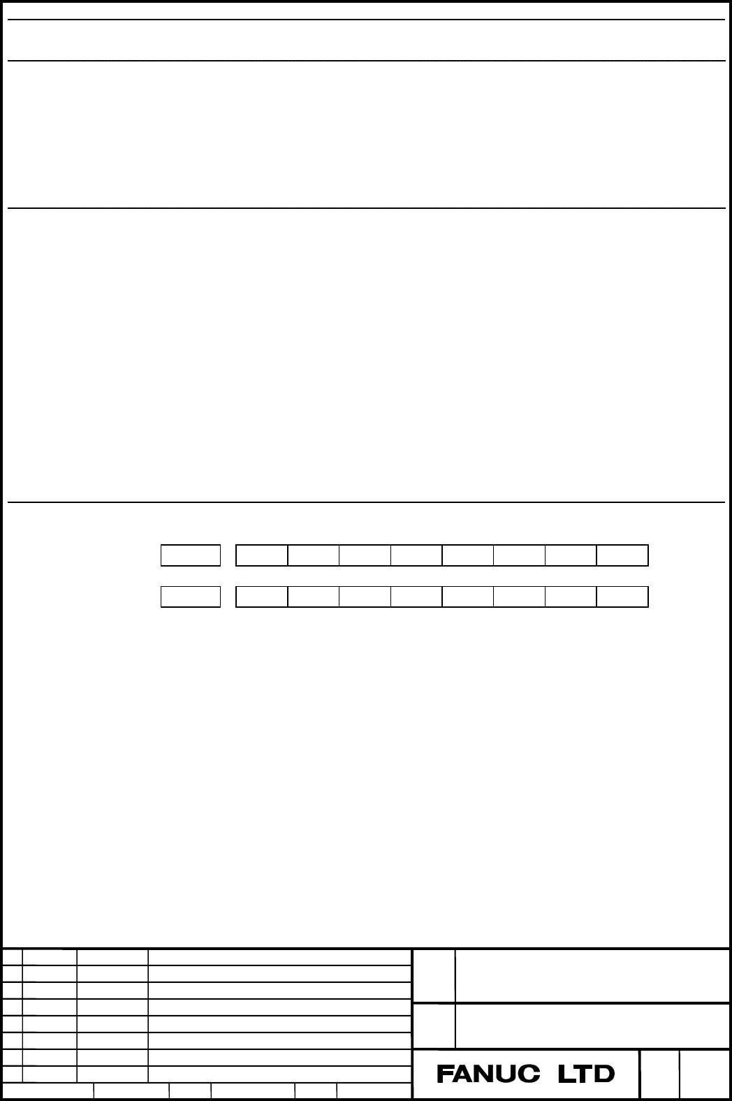
#7 #6 #5 #4 #3 #2 #1 #0
Gn296 DI8 DI7 DI6 DI5 DI4 DI3 DI2 DI1
Fn296 DM8 DM7 DM6 DM5 DM4 DM3 DM2 DM1
Contents Summary of Series 30i-MODEL A, DIAMETER AND RADIUS SETTING SWITCHING Additional Manual
- Page 1TECHNICAL REPORT NO. TMN 04/020E Date :Mar .30, 2004 General Manager of Software Laboratory FANUC Series 30i-A Newly additional functions 1. Communicate this report to: Your information only GE Fanuc-N, GE Fanuc-E FANUC Robotics MILACRON Machine tool builder Sales agency End user 2. Summary for Sale
- Page 2FANUC Series30i –A newly additional functions Drawing number Functions 1 A-79227E External Data Input 2 A-79226E One Touch Macro call 3 A-79196E Temporary absolute coordinate setting 4 A-79354E System alarm 5 A-79349E Touch Panel Control 6 A-79253E Distance coded linear scale interface 7 A-79364E Li
- Page 3FANUC Series 30i-MODEL A DIAMETER AND RADIUS SETTING SWITCHING Specifications FANUC Series 30i-MODEL A Title DIAMETER AND RADIUS SETTING SWITCHING Draw A-79340E No. Jan.06.’04 New design Ed. Date Design Description page 1/9 Date Jan.06.’04 Design. Apprv.
- Page 41.1 DIAMETER AND RADIUS SETTING SWITCHING FUNCTION Overview Usually, whether to use diameter specification or radius specification to specify a travel distance on each axis is uniquely determined by the setting of bit 3 (DIAx) of parameter No. 1006. However, this function enables switching between d
- Page 5・When switching is cancelled M code → Input signal OFF → Confirmation of output signal OFF → FIN If a diameter/radius specification switch signal is operated during automatic operation without following the sequences above, alarm PS5320 is issued. 2 If a diameter/radius specification switch signal i
- Page 6NOTE 1 When the diameter/radius specification switching state is to be cancelled using a reset or mode switching at the time of signal-based switching, the input signal needs to be operated. 2 Switching using a G code is cancelled by a reset. FANUC Series 30i-MODEL A Title DIAMETER AND RADIUS SETTIN
- Page 7Parameter #7 #6 #5 #4 #3 #2 #1 #0 3400 PGD [Input type] Parameter input [Data type] Bit path #5 PGD Specification of G10.9 specification (programmable diameter/radius specification switching) is: 0: Disabled. 1: Enabled. NOTE 1 The option for the diameter and radius setting switching function is req
- Page 8#7 #6 #5 #4 #3 #2 #1 #0 3194 DPM DPA [Input type] Parameter input [Data type] Bit path #2 DPA During diameter/radius specification switching, absolute coordinates, relative coordinates, and remaining travel distances are: 0: Displayed according to the specification during switching. 1: Displayed acc
- Page 9Signal Diameter/radius specification switch signals DI1 to DI8
[Classification] Input signal [Function] Switches between diameter specification and radius specification for each axis. [Operation] When a diameter/radius specification switch signal is set to 1, diameter/radius specification ope - Page 10Alarm Number Message Description PS5320 DIA./RAD. MODE CAN’T BE In any of the following states, diameter/radius specification SWITCHED . was switched: 1) When a buffered program is being executed 2) When a movement is being made on the axis Limitation - Feedrate A radius-based feedrate is specified
- Page 11Caution CAUTION When switching is performed from diameter specification to radius specification, the travel distance based on the same move command is doubled when compared with diameter specification. So, when switching from diameter specification to radius specification, ensure safety in machine o