FS 16i/18i-TA/TB Hobbing Function (for Lathe) Additional Manual Page 3
Additional Manual
PAGE
2/21
FANUC Series 16
i
/18
i
–TA/TB
HOBBING FUNCTION
EDT. DATE DESIG. DESCRIPTION
A – 78600E
NO.
TITLE
01 2001.09.17 Newly
1
HOBBING FUNCTION
General(G80.4, G81.4)
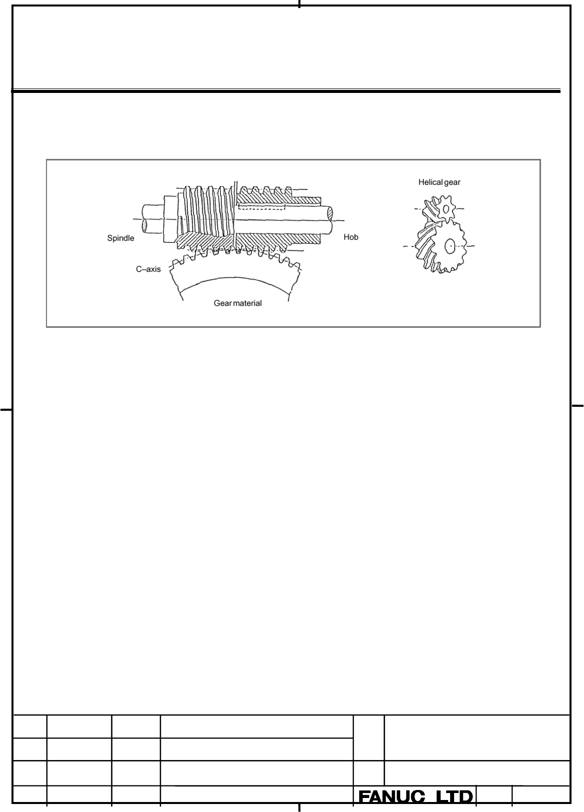
Gears can be cut by turning the workpiece (C–axis) in sync with the rotation
of the spindle (hob axis) connected to a hob. Also, a helical gear can be cut
by turning the workpiece (C–axis) in sync with the motion of the Z–axis (axial
feed axis).
Format
G81.4 R_ L_ Q_ P_ ;
R : Number of teeth (specifiable range: 1 to 500)
L : Number of hob threads (specifiable range: 1 to 30 with a sign)
- The sign of L specifies the direction of rotation of the C–axis.
- If L is positive, the C–axis rotates in the positive direction (+).
- If L is negative, the C–axis rotates in the negative direction (–)
Q: Module or diametral pitch
For metric input, specify a module.
(Units = 0.00001 mm; specifiable range = 0.01 to 25.0 mm)
For inch input, specify a diametral pitch.
(Units = 0.00001 inch
–1
; specifiable range = 0.01 to 250.0 inch
–1
)
P : Gear helix angle
(Units = 0.0001 deg; specifiable range = –90.0 to +90.0 deg)
P and Q must be specified when a helical gear is to be cut.
G80.4
;
Cancels synchronization between the hob axis and C-axis.
Contents Summary of FS 16i/18i-TA/TB Hobbing Function (for Lathe) Additional Manual
- Page 1TECHNICAL REPORT (MANUAL) No.TMN 01/153E Date : Oct. 25, 2001 General Manager of Software Development Center FANUC Series 16i/18i-TA/TB Hobbing Function (for Lathe) 1. Communicate this report to: Your information only ○ GE Fanuc-N, GE Fanuc-E FANUC Robotics MILACRON ○ Machine tool builder Sales agen
- Page 2FANUC Series 16i/18i-TA/TB HOBBING FUNCTION Specifications This specification may be modified for improvement without notice. FANUC Series 16i/18i –TA/TB TITLE HOBBING FUNCTION 01 2001.09.17 Newly A – 78600E NO. EDT. DATE DESIG. DESCRIPTION 1/21 PAGE
- Page 31 HOBBING FUNCTION General(G80.4, G81.4) Gears can be cut by turning the workpiece (C–axis) in sync with the rotation of the spindle (hob axis) connected to a hob. Also, a helical gear can be cut by turning the workpiece (C–axis) in sync with the motion of the Z–axis (axial feed axis). Format G81.4
- Page 4G code G code Group Function G80.4 Cancels synchronization between the hob axis and C- axis. G81.4 Starts synchronization between the hob axis and C- axis. 00 G82.4 Cancels C-axis servo delay compensation. G83.4 Executes C-axis servo delay compensation. G84.4 Records C-axis servo delay compensation.
- Page 5Helical Gear Compensation When a helical gear is to be cut, compensation for the C-axis, according to the amount of travel along the Z-axis (second axis) (axial feed) and gear helix angle, is required. Helical gear compensation is performed by adding compensation pulses, calculated using the followi
- Page 6Direction of Helical gear compensation 1 When bit 2 (HDR) of parameter No. 7700 = 1 (a) (b) (c) (d) +C +C +C +C +Z +Z +Z +Z -Z -Z -Z -Z C:+ C:+ C:+ C:+ Z:+ Z:+ Z:- Z:- P:+ P:- P:+ P:- Compensation Compensation Compensation Compensation direction :+ direction :- direction :- direction :+ (e) (f) (g)
- Page 7Setting helical gear axial feed axis The Z-axis (axial feed axis) is usually the second axis. However, any axis can be set as the Z-axis by setting the corresponding parameter appropriately (parameter No. 7709). C axis servo delay compensation The servo delay is proportional to the speed of the hob
- Page 8Method in which compensation for the delay when a command is specified is performed (G82.4, G83.4) G82.4 : Cancels C-axis servo delay compensation. G83.4 : Executes C-axis servo delay compensation. G81.4 R___ L___ ; Starts synchronization. M03 S100 ; Rotates the hob axis. G04 P2000 ; Causes the tool
- Page 9Notes (1) Specify the G83.4 block in G01 mode. Also, specify a feedrate using the F code. (2) Once G83.4 has been specified, another G83.4 command cannot be specified until compensation is canceled by specifying G82.4, or until C-axis synchronization is canceled. (3) Specify G83.4 once a constant ho
- Page 10C axis synchronous shift - C-axis handle interrupt During synchronization between the hob axis and C-axis, manual handle interrupt can be performed for the C-axis. The C-axis is shifted by the amount of the handle interrupt. - Synchronous shift by programming During synchronization between the hob a
- Page 11Retract function When the retract signal RTRCT is turned to “1” (the rising edge is detected) in auto mode or manual mode, the axis set in bit 0 (RTR) of the parameter No.7730 moves (retracts) by the amount set in the parameter No.7741. Upon the completion of retraction, the retract completion signa
- Page 12Signals Retract signal RTRCT
- Page 13(2) The stopping of retract by the reset RTRCT RTRCTF Moving Retract movement stopping RST One-rotation position manual set signal MSPC
- Page 14MSPCF
- Page 15Parameter #7 #6 #5 #4 #3 #2 #1 #0 1006 ROTx [Data Type] Bit axis ROTx Specifies whether each axis is a linear or rotation axis. 0 : linear axis 1 : rotation axis The C-axis (workpiece axis) must always be a rotation axis. #7 #6 #5 #4 #3 #2 #1 #0 3704 PCS [Data Type] Bit axis PCS Set this bit to 1 if
- Page 16#7 #6 #5 #4 #3 #2 #1 #0 7701 HBD DLY JHD SM3 SM2 SM1 [Data Type] Bit SM1, SM2, SM3 Specify the sampling frequency of the feedback pulses from the position coder in the hob function, SM3 SM2 SM1 Sampling times 0 0 0 4 0 0 1 1 0 1 0 2 0 1 1 16 1 0 0 32 1 1 0 4 1 1 1 4 JHD Specifies whether to enable C
- Page 177711 Gear ratio of the hob axis to the position coder [Data Type] Byte [Data Range] 1 to 20 [Unit of Data] 1 This parameter specifies the gear ratio of the hob axis to the position coder. 7712 Acceleration/deceleration time constant applied to the C-axis when it is in sync with the hob axis [Data Ty
- Page 187715 Magnification 1 for a G83.4-based C-axis servo delay compensation [Data Type] Word [Unit of Data] 0.0001 / 0.001 [Data Range] 500 to 2000 This parameter specifies magnification 1 for a G83.4-based C-axis servo delay compensation. #7 #6 #5 #4 #3 #2 #1 #0 7730 RTRx [Data Type] Bit axis RTRx The r
- Page 19Notice Retract (1) Feedrate override is not supported for retracting. (2) Interlock is supported for retracting. (3) Machine lock is supported for retracting. Retract completion signal is output when retract operation is completed in the machine lock condition. (4) Feed hold is not supported for ret
- Page 20Canned Cycle (1) Canned Cycle (from G81 to G89) can not be commanded in Hob synchro mode. Alarm 184 occurs if canned cycles are commanded. (2) G81.4(Starts Hob synchro) can not be commanded in canned cycle mode. Alarm 187 occurs if G81.4 is commanded. Thread Cutting (1) Retract is available in threa
- Page 21IS-D Hobbing function is not supported in IS-D system. Alarm 10 IMPROPER G-CODE 1. G80.4 to G84.4 are specified without option of Hobbing function. 2. G84.4 is specified in case parameter No.7701 bit 5 is set to 0 181 FORMAT ERROR IN G81.4 The G81.4 block is not of the BLOCK correct format. 1.R(numb
- Page 22186 PARAMETER SETTING A value for a parameter related ERROR to G81.4 is invalid. 1. The C-axis has not been specified as a rotation axis (bit 0 (ROT) of parameter No. 1006). 2. A value specified as the gear ratio of the hob axis to the position coder is invalid (parameter No. 7711). Note) These erro