Series 15i/150i - Model A Customer Board Descriptions Page 51
Descriptions
B-63322EN-2/01 11. LED INDICATORS
- 45 -
11.1 OVERVIEW
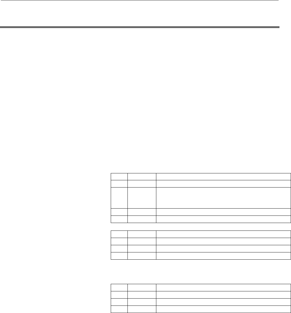
The customer's board has the LED indicators shown below.
If you ever suspect a malfunction, check the states of these LED
indicators.
1 2 3 4
STATUS¡¡¡¡ ← Green
ALARM ¡¡¡ ← Red
The following descriptions use an empty circle (¡), solid circle (●),
and a star (★) to indicate that the corresponding LED is off, on, or
blinking, respectively.
(1) Normal state and normal end of power-on time processing
STATUS : ●¡¡¡
ALARM : ¡¡¡
(2) If an alarm condition occurs (indicated on the STATUS LED
indicators)
No. STATUS NC status
0 ¡¡¡¡ The power is not on.
2 ¡●¡¡ There is no software in the application side.
There is an error in the task information table.
An optional parameter has not been set.
D ●¡●● DRAM test error.
F
●●●●
The power is on, but the processor has not started.
No. STATUS NC status
A ¡★¡★ ROM parity error on the system side.
B ★★¡★ ROM parity error on the application side.
E ¡★★★ A system alarm condition has occurred.
(3) If an alarm condition occurs (indicated by the ALARM LED
indicators)
No. ALARM NC status
3 ●●¡ SYSEMG condition (an NMI error has occurred).
4 ¡¡● DRAM parity error.
5 ●¡● Failure in the processor core power supply.
(4) Miscellaneous
If there is no system-side software when the customer's board is
installed, or if there is an error in the software, the nine LED
indicators in the CNC side blink, resulting in the CNC being
stopped.
Contents Summary of Series 15i/150i - Model A Customer Board Descriptions
- Page 1GE Fanuc Automation Europe Computer Numerical Controls 15i / 150i - Model A A Customer‘s Board Descriptions B-63322EN-2/01 TECHNOLOGY AND MORE
- Page 2
- Page 3B-63322EN-2/01 DEFINITION OF WARNING, CAUTION, AND NOTE DEFINITION OF WARNING, CAUTION, AND NOTE This manual includes safety precautions for protecting the user and preventing damage to the machine. Precautions are classified into Warning and Caution according to their bearing on safety. Also, suppl
- Page 4
- Page 5B-63322EN-2/01 Table of Contents Table of Contents DEFINITION OF WARNING, CAUTION, AND NOTE................................ NOTE ................................................................ ........................................................................ .................................
- Page 6Table of Contents B-63322EN-2/01 9 DEVELOPMENT ENVIRONMENT ENVIRONMENT ................................................................ ................................................................................................ ................................................................ 39
- Page 7B-63322EN-2/01 1. OVERVIEW 1 OVERVIEW The customer's board incorporates a high-speed RISC CPU for running application software created by a machine tool builder to implement his/her own functions. The use of a customer's board requires the machine tool builder's options as well as the basic options.
- Page 82. HARDWARE CONFIGURATION B-63322EN-2/01 2 HARDWARE CONFIGURATION -2-�
- Page 9B-63322EN-2/01 2. HARDWARE CONFIGURATION 2.1 OVERVIEW The hardware of the customer's board is configured as shown below: Main board Flash memory FANUC BUS Customer's board Code area (1.25 Mbytes) Data communication area (512 Kbytes) Data area (2 Mbytes) Fig. 2.1 (a) Hardware block diagram <1> Applic
- Page 103. SOFTWARE CONFIGURATION B-63322EN-2/01 3 SOFTWARE CONFIGURATION -4-�
- Page 11B-63322EN-2/01 3. SOFTWARE CONFIGURATION 3.1 OVERVIEW Customer's board system software This software is the system nucleus that runs on the customer's board. It is offered by FANUC. It performs the processing needed when the power is switched on. It also calls application software created by the mac
- Page 123. SOFTWARE CONFIGURATION B-63322EN-2/01 3.2 RAM ADDRESS AREA ASSIGNMENT The RAM areas on the customer's board are assigned addresses as shown below: To the FANUC bus 02000000H to 0203ffffH System code area (256 Kbytes) Code area (1.25 Mbytes), 02040000H to 0213ffffH which cannot Application code ar
- Page 13B-63322EN-2/01 3. SOFTWARE CONFIGURATION 3.3 SOFTWARE CONFIGURATION System software Initialization at System manager System call Start power-on actual processing System call library Application software Task information table Power-on time process Power-on time start address High-level task start ad
- Page 143. SOFTWARE CONFIGURATION B-63322EN-2/01 System calls When an application uses a system-provided process, it calls the corresponding function from a system call library. FANUC offers header files for calling functions from the system call library. The header files are used for developing application
- Page 15B-63322EN-2/01 3. SOFTWARE CONFIGURATION Task Task start address Task type Level Task No. 1 Start address of power-on time 0 0 process Task No. 2 Start address of high-level process 1 3 Task No. 3 Start address of normal-level 0 1 process Load the fields for task Nos. 4 to 16 and reserved for future
- Page 164. COMMUNICATION BETWEEN THE CNC AND CUSTOMER'S BOARD B-63322EN-2/01 4 COMMUNICATION BETWEEN THE CNC AND CUSTOMER'S BOARD - 10 -�
- Page 17B-63322EN-2/01 4. COMMUNICATION BETWEEN THE CNC AND CUSTOMER'S BOARD 4.1 APPLICATION SOFTWARE PROCESSING (a) Power-on time processing The application software is requested to perform the following power- on time processing when called from the system-side process. • Initialization, such as parameter
- Page 184. COMMUNICATION BETWEEN THE CNC AND CUSTOMER'S BOARD B-63322EN-2/01 4.2 PARAMETERS FOR APPLICATIONS The parameters listed below are available for application software. The application software can use these parameters for its own purposes. The memory storing these parameters is backed up by battery
- Page 19B-63322EN-2/01 4. COMMUNICATION BETWEEN THE CNC AND CUSTOMER'S BOARD 4.3 INPUT/OUTPUT SIGNALS FOR TRANSFER WITH APPLICATION SOFTWARE Sixty-four dedicated input signals and as many output signals are provided at the addresses shown below for data transfer between the application software and PMC. The
- Page 205. CNC/CUSTOMER'S BOARD WINDOW B-63322EN-2/01 5 CNC/CUSTOMER'S BOARD WINDOW - 14 -�
- Page 21B-63322EN-2/01 5. CNC/CUSTOMER'S BOARD WINDOW 5.1 OVERVIEW The CNC/customer's board windows are used for data communication between the CNC-side process and the application software. The CNC/customer's board windows are grouped according to the type of data being exchanged, as listed below. CNC/cust
- Page 225. CNC/CUSTOMER'S BOARD WINDOW B-63322EN-2/01 5.3 TIMING CHARTS (a) Transfer 1 synchronized with the high-level process (CNC-side process → application-side process) In transfer 1 synchronized with the high-level process, the following data is transferred from the CNC side to the application side. •
- Page 23B-63322EN-2/01 5. CNC/CUSTOMER'S BOARD WINDOW NOTE 1 The CNC side cannot write the next data before the application side completes reading of the current data. Keeping the CNC side waiting may reduce its throughput. Once it has started the high-level process, therefore, the application side should c
- Page 245. CNC/CUSTOMER'S BOARD WINDOW B-63322EN-2/01 (b) Transfer 2 synchronized with the high-level process (application-side process → CNC-side process) In transfer 2 synchronized with the high-level process, the following data is transferred from the application side to the CNC side. • Signals output fr
- Page 25B-63322EN-2/01 5. CNC/CUSTOMER'S BOARD WINDOW (c) Timing of application parameter transfer
PRMWT Parameter writing PRMWE Parameter reading Fig. 5.3 (c) Application parameter transfer • When the CNC-side process writes parameters to the CNC/customer's board window, it se - Page 265. CNC/CUSTOMER'S BOARD WINDOW B-63322EN-2/01 5.4 DETAILED DATA DESCRIPTIONS Data transfer control flag (CNC side → application side) 02400000H +0H +1H +2H +3H CRDY1 CRDY2 Reserved for future use Reserved for future use High-level data transfer 2 ready flag High-level data transfer 1 ready flag 0240
- Page 27B-63322EN-2/01 5. CNC/CUSTOMER'S BOARD WINDOW Data transfer control flag (application side → CNC side) 02404000H +0H +1H +2H +3H RRDY1 RRDY2 Reserved for future use Reserved for future use High-level data transfer 2 ready flag High-level data transfer 1 ready flag 02404004H +0H +1H +2H +3H P
- Page 285. CNC/CUSTOMER'S BOARD WINDOW B-63322EN-2/01 Signals input to application software (CNC side → application side) The input signals are transferred in synchronization with the high-level process. See Fig. 5.3 (a), "Transfer 1 synchronized with the high-level process," for detailed explanations about
- Page 29B-63322EN-2/01 5. CNC/CUSTOMER'S BOARD WINDOW Application parameters (CNC side → application side) If any of the application parameters is re-set by switching on the power, by using the MDI, or by executing G10, the new data is transferred to the CNC/customer's board window. See Fig. 5.3 (c), "Appli
- Page 305. CNC/CUSTOMER'S BOARD WINDOW B-63322EN-2/01 • Bit parameters 02400090H Offset Data No. Description Size + 0000H 0000 Bit parameter No. 1 1 byte + 0001H 0001 Bit parameter No. 2 1 byte + 0002H 0002 Bit parameter No. 3 1 byte : : : 1 byte : : : 1 byte + 000FH 0015 Bit parameter No. 16 1 byte • LONG
- Page 31B-63322EN-2/01 5. CNC/CUSTOMER'S BOARD WINDOW • Real number axis parameters 024020A0H Offset Data No. Description Size + 0000H 4000 Real number axis parameter No. 1 (first axis) 8 bytes + 0008H 4000 Real number axis parameter No. 1 (second axis) 8 bytes + 0010H 4000 Real number axis parameter No. 1
- Page 326. SYSTEM CALLS B-63322EN-2/01 6 SYSTEM CALLS - 26 -�
- Page 33B-63322EN-2/01 6. SYSTEM CALLS The following system call functions are offered in a library. 6.1 INTERRUPT DISABLE [Function name] sc_irt_mask [Function] Disables interrupts. [Format] void sc_irt_mask(); [Input] None. [Output] None. [Result] ---- [Note] The high-level process can start only when int
- Page 346. SYSTEM CALLS B-63322EN-2/01 6.4 MESSAGE OUTPUT (INTEGER: DECIMAL NUMBER) [Function name] sc_print_dec [Function] Displays a message (integer) in decimal notation. [Format] int sc_print_dec (int num, int dgt); [Input] int num : Number to be output. int dgt : Number of digits to be displayed (1 to
- Page 35B-63322EN-2/01 6. SYSTEM CALLS 6.5 MESSAGE OUTPUT (INTEGER: HEXADECIMAL NUMBER) [Function name] sc_print_hex [Function] Displays a message (integer) in hexadecimal notation. [Format] int sc_print_hex (unsigned int num, int dgt, int sup); [Input] Unsigned int num : Number to be output. int dgt : Numb
- Page 366. SYSTEM CALLS B-63322EN-2/01 6.7 DEBUG DISPLAY (SCREEN CLEAR) [Function name] sc_screen_clr [Function] Clears the entire debug display screen. [Format] void sc_screen_clr(); [Input] None. [Output] None. [Result] The output message can be viewed on the CNC-side message function screen. [Note] See t
- Page 37B-63322EN-2/01 6. SYSTEM CALLS 6.9 DEBUG DISPLAY (CHARACTER STRING) [Function name] sc_screen_str [Function] Displays a character string, starting at the position indicated by the display pointer. [Format] int sc_screen_str (char *str); [Input] char *str: Pointer to the character string to be output
- Page 386. SYSTEM CALLS B-63322EN-2/01 6.11 ARBITRATION FOR CONTINUOUS UPDATE [Function name] sc_access_wait [Function] Conducts arbitration between the application software and the CNC side, if the application software attempts to continuously update an area that may be accessed by the CNC side. [Format] v
- Page 39B-63322EN-2/01 6. SYSTEM CALLS 6.12 CACHE CONTROL [Function name] sc_cache_off [Function] Turns off the data or instruction cache in the processor. [Format] void sc_cache_off (int kind); [Input] int kind: Cache specification (0 = data cache and 1 = instruction cache) [Output] None. [Result] ---- [No
- Page 406. SYSTEM CALLS B-63322EN-2/01 X-coordinate 0 75 0 (0,0) Y- corrdinate (75,16) 16 Debug display screen configuration - 34 -�
- Page 41B-63322EN-2/01 7. DEVELOPMENT SUPPORT FUNCTIONS 7 DEVELOPMENT SUPPORT FUNCTIONS - 35 -�
- Page 427. DEVELOPMENT SUPPORT FUNCTIONS B-63322EN-2/01 The following debugging functions are supported: Monitor function This function displays the statuses of DI/DO data (G180 to G187/F180 to F187), diagnostic data (processing time and peak time of task No. 2), and data transfer flags (data transfer 1, da
- Page 43B-63322EN-2/01 8. CONTROL PARAMETERS 8 CONTROL PARAMETERS - 37 -�
- Page 448. CONTROL PARAMETERS B-63322EN-2/01 #7 #6 #5 #4 #3 #2 #1 #0 1011 NCB [Input type] Parameter input [Data type] Bit axis NOTE After setting this parameter, switch the power off and then back on again. #2 NCB Specifies whether a specific axis is to be used on the customer's board, as follows: 0: Axis
- Page 45B-63322EN-2/01 9. DEVELOPMENT ENVIRONMENT 9 DEVELOPMENT ENVIRONMENT - 39 -�
- Page 469. DEVELOPMENT ENVIRONMENT B-63322EN-2/01 9.1 OVERVIEW Machine tool builders are requested to create application software for the customer's board. •Use a commercially available personal computer for program development (such as editing, compilation, and load file (MEM file) creation). •Refer to the
- Page 47B-63322EN-2/01 10. CAUTIONS FOR CODING 10 CAUTIONS FOR CODING - 41 -�
- Page 4810. CAUTIONS FOR CODING B-63322EN-2/01 10.1 OVERVIEW When creating application programs, observe the following cautions: 1. Do not perform division by zero. 2. When using data of type float or double, do not perform an arithmetic operation on that data with NaN (nonnumeric) held. 3. Before convertin
- Page 49B-63322EN-2/01 10. CAUTIONS FOR CODING The coding in the above example must be changed as follows: extern int count; static int count2; count2 = 0; for ( ; ; ) { count ++; count2 ++; if ( count > 100000 ) break; if ( count2 >= 500 ) { sc_access_wait (); count2 = 0; } } WARNING If an application prog
- Page 5011. LED INDICATORS B-63322EN-2/01 11 LED INDICATORS - 44 -�
- Page 51B-63322EN-2/01 11. LED INDICATORS 11.1 OVERVIEW The customer's board has the LED indicators shown below. If you ever suspect a malfunction, check the states of these LED indicators. 1 2 3 4 STATUS¡¡¡¡ ← Green ALARM ¡¡¡ ← Red The following descriptions use an empty circle (¡), solid circle (●), and a
- Page 5212. CUSTOMER'S BOARD MANIPULATION B-63322EN-2/01 12 CUSTOMER'S BOARD MANIPULATION - 46 -�
- Page 53B-63322EN-2/01 12. CUSTOMER'S BOARD MANIPULATION 12.1 DEDICATED CUSTOMER'S BOARD PARAMETERS Overview The dedicated customer's board parameters are those dedicated to customer's board control. They can be: • Referenced from the customer's board side, • Output to and input from external units, • Rewri
- Page 5412. CUSTOMER'S BOARD MANIPULATION B-63322EN-2/01 Displaying dedicated customer's board parameters The dedicated customer's board parameters are displayed on the CUSTOMER'S BOARD (PARAMETER) screen. They can be set up, input from, and output to external units, also using this screen. To display the C
- Page 55B-63322EN-2/01 12. CUSTOMER'S BOARD MANIPULATION Setting dedicated customer's board parameters • Selecting the mode Select MDI mode, or press the emergency stop button to bring the CNC to an emergency stop. • Positioning the cursor Move the cursor to the desired dedicated customer's board parameter.
- Page 5612. CUSTOMER'S BOARD MANIPULATION B-63322EN-2/01 • Bit off: 0 Pressing soft key [OFF:0] resets a bit of a bit parameter to 0. The bit is selected by the cursor. If all bits are selected by the respective cursors, all bits are reset to 0. NOTE 1. Setting the data triggers a parameter transfer to the
- Page 57B-63322EN-2/01 12. CUSTOMER'S BOARD MANIPULATION Method 4 (with a file number specified, No. 2) (1) Display the CUSTOMER'S BOARD (PARAMETER) screen. (2) Select MDI mode. (3) Press soft key [PUNCH]. (4) Press the address key. N (5) Key in a file number. (6) Press soft key [EXECUTE]. Method 5 (with a
- Page 5812. CUSTOMER'S BOARD MANIPULATION B-63322EN-2/01 (6) Key in a file name. (7) Press soft key [FILE NAME"]. (8) Press soft key [EXECUTE]. Method 3 (with an input file specified using a file number, No. 1) (1) Display the CUSTOMER'S BOARD (PARAMETER) screen. (2) Select MDI mode. (3) Bring the CNC to an
- Page 59B-63322EN-2/01 12. CUSTOMER'S BOARD MANIPULATION Output format of dedicated customer's board parameters The dedicated customer's board parameters are categorized according to their data types, as follows: • Bit • Integer • Integer axis • Real number • Real number axis A parameter of type bit is repr
- Page 6012. CUSTOMER'S BOARD MANIPULATION B-63322EN-2/01 • Format of parameters of type integer N ***** P ****** ; A number that follows letter N is a parameter number. A number that follows letter P is the value (integer) of the parameter. The semicolon represents an end-of-block code. (It is LF in ISO cod
- Page 61B-63322EN-2/01 12. CUSTOMER'S BOARD MANIPULATION • Format of parameters of type real number axis N ***** A ** P ****** A ** P ****** ... ... ; A number that follows letter N is a parameter number. A number that follows letter A is a controlled axis number (1 or greater) A number that follows letter
- Page 6212. CUSTOMER'S BOARD MANIPULATION B-63322EN-2/01 Programmable input of dedicated customer's board parameters • Overview The values of the dedicated customer's board parameters can be modified from programs. • Command format Format G10L55; Selects the input mode for dedicated customer's board paramet
- Page 63B-63322EN-2/01 12. CUSTOMER'S BOARD MANIPULATION • Exercises 1. Setting bit 0 of parameter No. 0000 of type bit G10L55; Selects input mode for dedicated customer's board parameters. N0000 R00000001; Sets data. G11; Deselects input mode. 2. Changing the values of the Z axis (third axis) and A axis (f
- Page 6412. CUSTOMER'S BOARD MANIPULATION B-63322EN-2/01 12.2 DEVELOPMENT SUPPORT FUNCTIONS Overview The development support functions help machine tool builders develop customer's board control software. The following development support functions are available: • Monitor function • Memory display function
- Page 65B-63322EN-2/01 12. CUSTOMER'S BOARD MANIPULATION 12.2.1 Monitor Function • Overview The monitor function displays the following data: • Input/output signals (G180 to G187/F180 to F187) • Diagnostic data • Data transfer control flag Monitor function display and manipulation To display the CUSTOMER'S
- Page 6612. CUSTOMER'S BOARD MANIPULATION B-63322EN-2/01 • CONTROL FLAG These boxes display the states of the control flags for data transfer between the CNC and board sides. NOTE The displayed values reflect only the instantaneous states of the control flags. The displayed values may not necessarily match
- Page 67B-63322EN-2/01 12. CUSTOMER'S BOARD MANIPULATION 12.2.2 Memory Display Function • Overview The memory display function displays the contents of the customer's board side memory. Memory display function display and manipulation To display the CUSTOMER'S BOARD (MEMORY) screen, press the function menu
- Page 6812. CUSTOMER'S BOARD MANIPULATION B-63322EN-2/01 • Address specification To specify an address, input a physical address on the customer's board, and the press the [ADDRESS SEARCH] soft key. If the input address data is invalid, a warning is issued. • Data length switching Pressing soft key [BYTE],
- Page 69B-63322EN-2/01 12. CUSTOMER'S BOARD MANIPULATION 12.2.3 Breakpoint Function • Overview The breakpoint function checks whether the processor has executed an instruction at a specified address on the customer's board. Breakpoint function display To display the CUSTOMER'S BOARD (BREAK POINT) screen, pr
- Page 7012. CUSTOMER'S BOARD MANIPULATION B-63322EN-2/01 Breakpoint function manipulation • Address specification Key in a physical address that exists on the customer's board, then press soft key [INPUT]. The specified address is displayed as a breakpoint. If the specified address data is invalid, a warnin
- Page 71B-63322EN-2/01 12. CUSTOMER'S BOARD MANIPULATION 12.2.4 Data Output Function • Overview The data output function outputs data between the specified addresses on the customer's board to a memory card in binary form. Data output function display To display the CUSTOMER'S BOARD (DATA OUTPUT) screen, pr
- Page 7212. CUSTOMER'S BOARD MANIPULATION B-63322EN-2/01 Data output function manipulation • Start address specification Press the cursor keys to position the cursor to the "START ADDRESS." Key in a physical address on the customer's board, then press the [INPUT] soft key. The specified address is displayed
- Page 73B-63322EN-2/01 12. CUSTOMER'S BOARD MANIPULATION 12.2.5 Data Escape Function • Overview The data escape function saves the data between the specified addresses on the customer's board to a save area at regular intervals (8 ms). Data escape function display To display the CUSTOMER'S BOARD (ESCAPE) sc
- Page 7412. CUSTOMER'S BOARD MANIPULATION B-63322EN-2/01 • END ADDRESS These boxes specify the end addresses of the data to be saved. (Each address is a physical address on the customer's board.) • BUFFER AREA These boxes display the area to which data is to be saved. (The addresses are physical addresses o
- Page 75B-63322EN-2/01 12. CUSTOMER'S BOARD MANIPULATION • Specifying sets to be used Up to five sets of addresses can be specified for saving. After setting a desired set of start and end addresses, set the cursor to "(0:ON 1:OFF)," using the cursor keys, and then press the [ON:1] soft key. If the start or
- Page 7612. CUSTOMER'S BOARD MANIPULATION B-63322EN-2/01 Save area The BUFFER AREA boxes indicate the location where data is to be saved. In single mode, saving ends once the buffer area is full. In ring mode, the buffer area is used in a ring manner. When there is no free space in the buffer area, a new da
- Page 77B-63322EN-2/01 12. CUSTOMER'S BOARD MANIPULATION Saving Data saving is performed immediately before task No. 2 is started. In every cycle, data between the addresses in each effective set is saved sequentially (from set 1 to set 5). • Examples Effective set Set 2 Start address 0x02400000 End address
- Page 7812. CUSTOMER'S BOARD MANIPULATION B-63322EN-2/01 12.2.6 Message Function • Overview The message function displays the message data output from the customer's board control software. Message function display To display the CUSTOMER'S BOARD (MESSAGE) screen, press the function menu key, and then press
- Page 79B-63322EN-2/01 12. CUSTOMER'S BOARD MANIPULATION • UPDATE This box indicates whether message data display update has started or ended. Message function manipulation • Presetting Pressing the [POINTER PRESET] soft key sets both the top and bottom addresses to the start address of the buffer area. • D
- Page 8012. CUSTOMER'S BOARD MANIPULATION B-63322EN-2/01 12.2.7 Debug Display Function • Overview The debug display function displays a simple debugging screen created using the customer's board control software. Debug display function display To display the CUSTOMER'S BOARD (DEBUG SCREEN) screen, press the
- Page 81B-63322EN-2/01 12. CUSTOMER'S BOARD MANIPULATION 12.2.8 Waveform Diagnosis Function • Overview The "Contents of specified memory" have been added as traceable data to the conventional waveform diagnosis function. Refer to the "FANUC Series 15i/150i-MA Maintenance Manual (63325EN)" for detailed descr
- Page 8212. CUSTOMER'S BOARD MANIPULATION B-63322EN-2/01 • ACCESS SIZE This box is used to specify the amount of memory to be accessed for tracing at any one time. 0: One-byte length (signed) 1: One-byte length (unsigned) 2: Two-byte length (signed) 3: Two-byte length (unsigned) 4: Four-byte length (signed)
- Page 83B-63322EN-2/01 12. CUSTOMER'S BOARD MANIPULATION NOTE 1. The traced data is clamped within the following range: -999999999 ≤ data ≤ 999999999 2. The following restrictions are imposed on the least significant digit of the address according to the access size: One-byte length: No restriction Two-byte
- Page 8412. CUSTOMER'S BOARD MANIPULATION B-63322EN-2/01 4601 File output format [Input type] Parameter input [Data type] Integer [Valid data range] 0 to 1 This parameter specifies a format to be used in outputting data traced by the waveform diagnosis function to an external input/output unit, as follows:
- Page 85B-63322EN-2/01 12. CUSTOMER'S BOARD MANIPULATION 4732 Memory address specification 1 [Input type] Parameter input [Data type] Integer [Valid data range] 0 to 999999999 This parameter specifies a memory address at which specified-memory tracing is to be performed using trace data 1 of the waveform di
- Page 8612. CUSTOMER'S BOARD MANIPULATION B-63322EN-2/01 4735 Memory address specification 2 [Input type] Parameter input [Data type] Integer [Valid data range] 0 to 999999999 This parameter specifies a memory address at which specified-memory trace is to be performed using trace data 2 of the waveform diag
- Page 87B-63322EN-2/01 12. CUSTOMER'S BOARD MANIPULATION 4738 Memory address specification 3 [Input type] Parameter input [Data type] Integer [Valid data range] 0 to 999999999 This parameter specifies a memory address at which specified-memory trace is to be performed using trace data 3 of the waveform diag
- Page 8812. CUSTOMER'S BOARD MANIPULATION B-63322EN-2/01 4741 Memory address specification 4 [Input type] Parameter input [Data type] Integer [Valid data range] 0 to 999999999 This parameter specifies the memory address at which specified- memory trace is to be performed using trace data 4 of the waveform d
- Page 89B-63322EN-2/01 12. CUSTOMER'S BOARD MANIPULATION 12.4 MISCELLANEOUS (1) Displaying the software series and edition The software series and edition of the customer's board control software can be viewed on the system configuration screen. For the software of the customer's board control system side,
- Page 90B-63322EN-2/01 INDEX INDEX APPLICATION SOFTWARE ..................................13 A INTERRUPT DISABLE ...............................................27 APPLICATION SOFTWARE PROCESSING.............. 11 INTERRUPT ENABLE ................................................27 ARBITRATION FOR CONTINUOUS U
- Page 91Revision Record FANUC Series 15i/150i-MODEL A Customer’s Board DESCRIPTIONS (B-63322EN-2) 01 Mar., 2000 Edition Date Contents Edition Date Contents
- Page 92
- Page 93EUROPEAN HEADQUARTERS – BELGIUM / NETHERLANDS GRAND-DUCHÉ DE LUXEMBOURG GE Fanuc Automation Europe S.A. GE Fanuc Automation Europe S.A. - Netherlands Branch - Zone Industrielle Postbus 7230 - NL-4800 GE Breda L-6468 Echternach Minervum 1603A - NL-4817 ZL Breda ( (+352) 727979 - 1 ( (+31) 76-5783 201
- Page 94• No part of this manual may be reproduced in any form. • All specifications and designs are subject to change without prior notice. The export of this product is subject to the authorization of the government of the country from where the product is exported. In this manual we have tried as much as