Connection of Servo Amplifier Additional Manual Page 4
Additional Manual
TITLE
DRAW
.
No.
4 / 6
Page
FANUC LTD
DESCRIPTION DESIGN DATE
EDIT
Connection of servo amplifier βiSVSP
and power failure backup module
A
-72562-031
3. Detail of cable connection
Please refer to DESCRIPTIONS (A-53866-464) except for cables below.
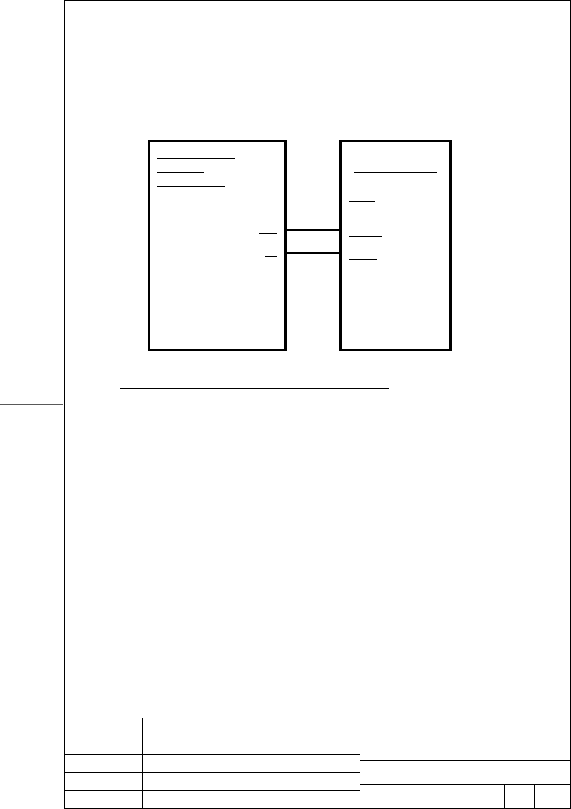
(1) Detail of cable K94
For power source (DC24V) cable of power failure backup module
Specifications of the third party switching power supply
<1> Input voltage range
170 VAC to 264 VAC (continuous)
240 VDC to 373 VDC (in power failure backup operation, 1 min. max.)
* Some types of switching power supply cannot be driven continuously on DC
power and, therefore, the specifications of some of these types state that they
"cannot be driven on DC power". Even such types can be driven on DC power
if they satisfy the time requirement for power failure backup (1 min. max.).
<2> Output current
Depends on the current consumption of the device to be connected.
<3> Operation at and below the input voltage specifications
The state in which the input voltage is 0 VDC to 240 VDC may keep for a maximum
of one minute. Even in this case, the switching power supply must be free from
damage and no voltage exceeding the specification range tolerable by β
iSVSP,
CNC, PMC and others (24V+10%) may be output.
Power source
(DC24V)
of third party
24
V
0
V
K94
Power failure
backup module
CX14
(1) 24V
(2) 0V
(3)
Contents Summary of Connection of Servo Amplifier Additional Manual
- Page 1Connection of servo amplifier βiSVSP and power failure backup module 1. Type of applied documents Name FANUC SERVO AMPLIFIER βiSV series DESCRIPTIONS Spec. No./Ver. A-72562-031 2. Summary of Change Group Name / Outline New, Add Applicable Correct, Del Date Basic Function Optional Function Unit Maint
- Page 2Connection of servo amplifier βiSVSP and power failure backup module 1. Overview This documents describes about the connection of βiSVSP and power failure backup module. Please also refer to DESCRIPTIONS (A-53866-464) for the details. All specifications and designs are subject to change without noti
- Page 32. Connection diagram Connection of servo amplifier βiSVSP TITLE and power failure backup module DRAW. No. A-72562-031 EDIT DATE DESIGN DESCRIPTION FANUC LTD Page 3/6
- Page 43. Detail of cable connection Please refer to DESCRIPTIONS (A-53866-464) except for cables below. (1) Detail of cable K94 For power source (DC24V) cable of power failure backup module Power source Power failure (DC24V) backup module of third party CX14 24V (1) 24V K94 0V (2) 0V (3) Specifications of
- Page 5<4> Retention time at an instantaneous power break 30 msec or greater * Generally, the retention time given on the catalog is the value assumed when the load factor is 100%. If the retention time requirement of 30 msec or greater is not satisfied, the retention time can be extended by reducing the l
- Page 6(2) Detail of cable K95 Interface cable of βiSVSP and power failure backup module SVSP JX6 JX1A (9) *CRDY (9) (12) 0V (10) Connector Example (HONDA) Connector Example (HONDA) Connector PCR-E20FA Connector PCR-E20FA Hausing PCR-V20LA Hausing PCR-V20LA Cable specification: 0.09mm2 twisted pair sealed