FS 16i/18i/21i Additional Manual Page 6
Additional Manual
6/11
A- 77987EN
DRAW.No.
FANUC Series 16
i
/18
i
/21
i
Specifications of Distance Coded Linear
Scale Interface Ex
p
ansion
Title
Newly Registered
DESCRIPTIONDESIGNE
99.12.03
DATE
01
EDIT.
2.1.2.2 Absolute command and incremental command
As described in Item 2.1.2 (4), the axis is positioned to the commanded end point after the
reference point is established.
The operation at this time is as follows.
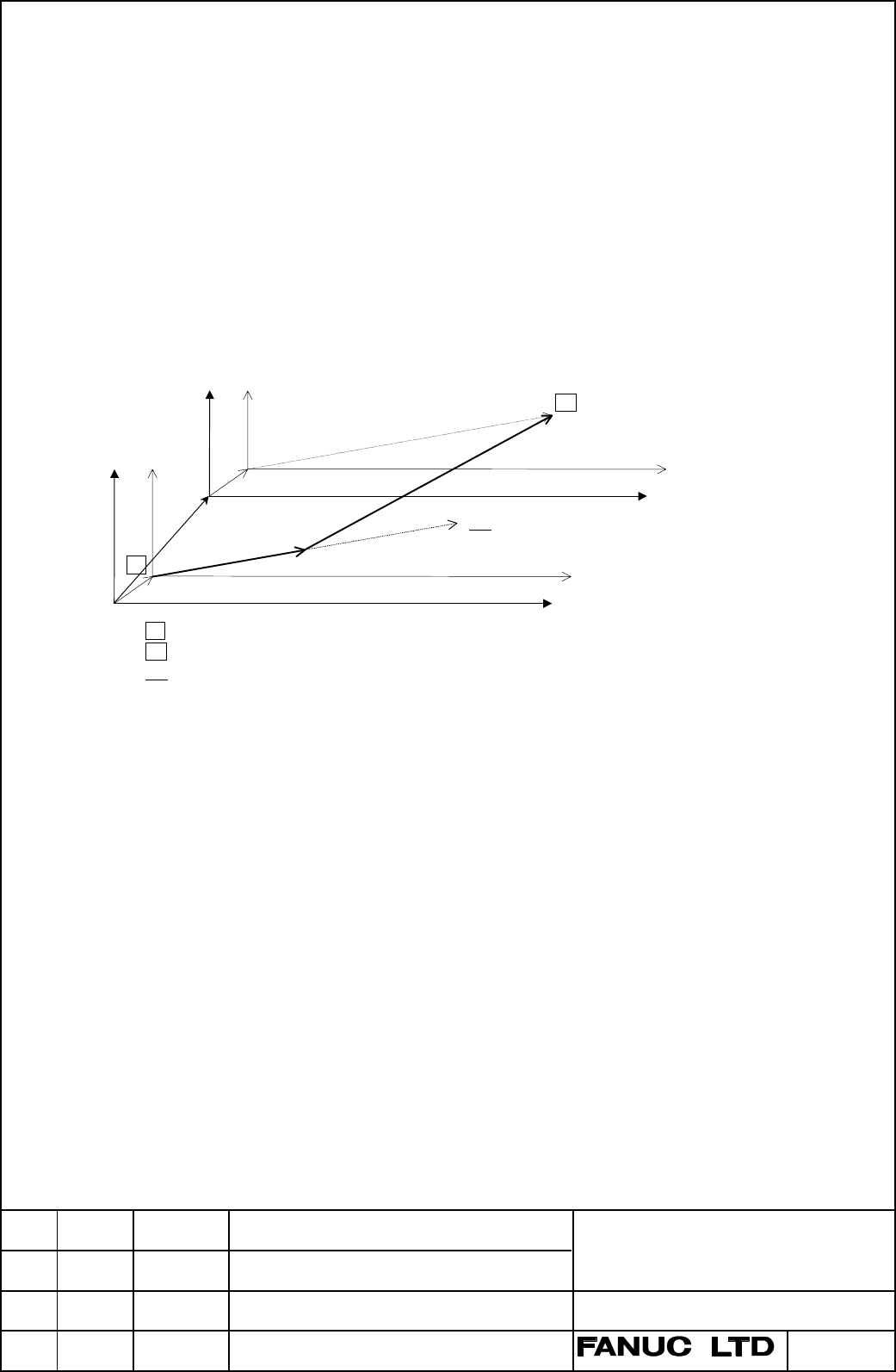
(1) When an absolute command is specified
The axis moves to the end point in the new coordinate system which is established by Item
2.1.2 (3).
The behavior of the axis is shown on a bold line in the figure below when for instance "G90
G00 Xxx.Yyy; (M system)" or "G00 Xxx.Zyy; (T system)" is commanded.
However, the figure shows each position, and it does not show an actual tool path.
Fig.5 Operation of absolute command
SP : Start point
EP
: Actual end point ((xx,yy) in new coordinate system)
EP’ : End point when G00 is commanded ((xx,yy) in old coordinate system)
A : The point where the reference points are established
ZOFS : Workpiece zero point offset value
(a,b) : Difference between coordinate systems before and after the reference point establishment
EP’ (xx,yy)
A
Old machine coordinate system
•
not exact
•
ZOFS
Old workpiece coordinate system
•
not exact
•
SP
New workpiece coordinate system
•
exact
•
New machine coordinate system
•
exact
•
EP (xx,yy)
ZOFS
(a,b)
Contents Summary of FS 16i/18i/21i Additional Manual
- Page 1FANUC Series 16i/18i/21i Specifications of Distance Coded Linear Scale Interface Expansion CONTENTS 1. Outline 2 2. Specifications 2 3. Parameter 11 TitleFANUC Series 16i/18i/21i Specifications of Distance Coded Linear Scale Interface Expansion 01 99.12.03 Newly Registered DRAW.No. A- 77987EN EDIT.
- Page 21. Outline Intervals of reference marks of distance coded linear scale are variable. That is, if CNC can know the interval of reference marks, it can know an absolute position on the scale. When the axis is moved by G00 command or JOG mode, this function establishes the reference point by measuring
- Page 3• Programmable mirror image (M system) • Scaling (M system) • High-precision contour control (M system) • AI nano contour control (M system) • Mirror image for double turrets (T system) Note When the above condition is not satisfied, the reference point establishment operation is not started, and be
- Page 4The specification of reference point establishment by detecting some reference marks is compatible with the former one. The restriction, parameter setting method, and so on are also the same as the former specifications. Please refer to "FANUC Series 16/18/16i/18i/21i distance coded linear scale int
- Page 5(3) When, in the same block, the reference point establishment operation is executed for some target axes, and it is not executed for other target axes. For instance, when the reference point of X axis has been established, and the reference points of Y and Z axis have not been established yet, and
- Page 62.1.2.2 Absolute command and incremental command As described in Item 2.1.2 (4), the axis is positioned to the commanded end point after the reference point is established. The operation at this time is as follows. (1) When an absolute command is specified The axis moves to the end point in the new
- Page 7(2) When an Incremental command is specified Each axis moves only by the commanded distance. That is, the behavior of the axis is shown on a bold line in the figure below. However, the figure shows each position, and it does not show an actual tool path. The coordinate value of the end point becomes
- Page 82.1.2.4 Stopping by feed hold The operation becomes a non linear positioning when execution is restarted after the feed hold during the reference point establishment operation. And the reference point establishment operation is not restated in this block. The reference point establishment operation
- Page 92.2 Reference point establishment by JOG feed 2.2.1 Requirement In satisfying the followings, the reference point establishment operation is automatically started. (1) When feed axis and direction selection signal +Jn or -Jn (G100/G102) is input in the JOG mode to the axis which the reference point
- Page 10The operation of the above-mentioned is shown in timing chart. JOG +Jn(-Jn) Reference marks ZRFn Feedrate JOG feedrate FL speed Time Fig.7 Timing chart for reference point establishment operation by JOG feed 2.2.2.1 Stopping by feed axis and direction selection signal The axis stops when the feed ax
- Page 112.3 Notes (1) PMC axis control The reference point establishment operation is not executed by the rapid traverse (axis control command 00h) and the JOG feed (axis control command 06h) of PMC axis control. (2) Rapid traverse operation by command other than G00 The reference point establishment operat