To Meet the Requirement of the EMC Directive Additional Manual Page 35
Additional Manual
A-72937EN/11
To meet the requirement of the EMC Directive
TMN06007E_A-72937EN_11.DOC
- 33 -
2) Motor side
Connect the shield wire to the ground through the ground terminal in the
connector that is led to the grounded motor body.
Detailed connection method is described in the following paragraphs in
item 4.3.2(3).
(3) Shield treatment of each model at motor side
1) Model α1 to α2.5
a) Feed back cable
Use double layered shield cable. Leave the both inner and outer shield
open in the motor end.
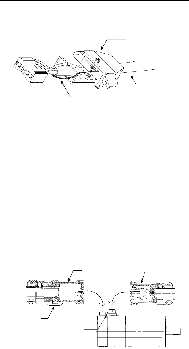
b) Power cable (Refer to the above figure)
Use shield cable. Clamp the shield wire and the earth wire for the
connector shell together.
2) Model α3 and over
a) Feed back cable
Use double layered shield cable.
Connect the outer shield to the contact ‘L’ in the cannon connector with
the drain wire or short connecting wire.
◎The shield clamp adapter and bridge wire (FG mesh) are not necessary
except for the older version that either of the following conditions is
met.
Conditions:
1. The motor employs
α pulsecoder (Spec. No.: A06B-0***-B*75~
B*77, B*86
~B*89) but its manufactured date is before May ‘96.
2. The motor employs SERIAL A pulsecoder. (Spec. No.: A06B-0***-
B*84,B*85)
Note) The current motor, which does not meet any of above conditions,
has the feedback connector in which the contact ‘L’ has a connection
with its shell and motor body. That is why the connection of current
signal cable does not require using shield clamp adapter or FG
mesh as is required below.
When either of above condition is met, apply the following two step
measure instead of connecting the shield to the contact ‘L’.
Power connector
Shield cable
Earth wire
Shield clamp
adapter
FG mesh
Power connector
Feedback connector
Contents Summary of To Meet the Requirement of the EMC Directive Additional Manual
- Page 1TECHNICAL REPORT (MANUAL) NO.TMN 06/007E Date January 25, 2006 General Manager of CNC Laboratory Issue of Guideline; "To meet the requirement of the EMC Directive" 1. Communicate this report to: O Your information only O GE Fanuc-N, GE Fanuc-E FANUC Robotics MILACRON O Machine tool builder Sales age
- Page 2To meet the requirement of the EMC Directive 11th Edition / January 11 2006 CNC Laboratory FANUC LTD A-72937EN/11 To meet the requirement of the EMC Directive TMN06007E_A-72937EN_11.DOC
- Page 3Table of contents 1 Forewords・・・・・・・・・・・・・・・・・・・・・・・・ 3 2 Conformity evaluation test・・・・・・・・・・・・・・・・ 4 2.1 Items of conformity test for FANUC products・・・・・・・・ 4 2.2 Certification for a machine series・・・・・・・・・・・・・・ 5 3 Guidelines for electric design・・・・・・・・・・・・・・・ 6 3.1 Cabinet・・・・・・・・・・・・・・・・・・・・・・・
- Page 4(14) I/O link cable・・・・・・・・・・・・・・・・・・・・・・・・・・・・・ 30 (15) DI/DO cable・・・・・・・・・・・・・・・・・・・・・・・・・・・・・ 30 (16) Relay output cable・・・・・・・・・・・・・・・・・・・・・・・・・・ 31 (17) Communication cable for I/0 unit Model B・・・・・・・・・・・・・・・・ 31 (18) Input power cable・・・・・・・・・・・・・・・・・・・・・・・・・・ 31 4.3.2 Cables to be connected
- Page 51 Forewords In EU, the EMC Directive became mandatory on 1. January 1996. To show the conformity, CE marking is required to apply on products. As it is known, the CE mark is primarily for final products for users. FANUC’s CNCs and amplifiers are essentially parts of machine tools, nevertheless, cons
- Page 62 Conformity evaluation test In September 1995, the generic immunity standard (EN50082-2 *) was harmonized by EU. Consequently, a manufacturer can declare, by themselves, product conformity to the EMC Directive by indicating that the product meets relevant harmonized standards. * The generic immunit
- Page 72.2 Certification for a machine series When an MTB intends to get a CB's EMC certificate for their machine, it is said possible that the MTB can get the certificate for their machine including a machine series through a documentation-based inspection if they construct their machines strictly followi
- Page 83 Guidelines for electric design As the biggest concern is how we can get our products to pass the test, this document concentrates in this point From MTB’s viewpoint, we can classify the tests listed in the previous section as follows. Group 1 1) Radiated emission Group 2 3) Conducted emission Grou
- Page 91) Units that have oscillators in it should be put in an enclosed metal cabinet. 2) Ground all the conductive stuffs that are electrically floating. 3) Stuffs that could be antenna (e.g. signal cable with high frequency) should be surrounded by grounded metal. (Shielding) The countermeasure for EMC
- Page 103.1.4 Close holes electrically “Close holes electrically” means to use conductive stuff (normally metal) as a cover and the cover is connected to a cabinet in low impedance. The following is the standard configuration. That is, eliminate paint from circumference of a cover and a cabinet hole to get
- Page 113.1.6 Eliminate conductive stuffs floating electrically As described earlier in this chapter, be sure to ground conductive stuffs that are floating electrically in a cabinet. Those floating stuffs are easily influenced by electric wave and they immediately act as antenna. Metal fittings prepared for
- Page 12Wrong Right Shielded area Cabinet Cabinet CNC Amplifier CNC Amplifier Noise AC AC input input Other Other Other Other device device device device Breaker Breaker Noise Filter Noise Filter Surge Surge Transformer absorber Transformer absorber Metal sheets normally The separation do isthe (shielding)
- Page 13Recommendable noise filters for EMC (2) PSM-5.5, PSMR PSM-11, 15 PSM-26 ~ 37 PSM-45 α,β Power SVU1, 2, 3 / βseries supply PSM-18HV, 30HV α(HV) - PSM-45HV PSM-75HV module PSMV-11HV αi PSM-5.5i PSM-11i , 15i PSM-26i ~ 37i - Rated current 30A 80A 150A 200A Rated voltage AC460V Annex Outer dimension 3-F
- Page 14Recommendable noise filters for EMC (4)/For neutral point grounding system only PSM-5.5, PSMR PSM-11, 15 PSM-26 ~ 37 PSM-45 α,β Power SVU1, 2, 3 / βseries supply PSM-18HV, 30HV α(HV) - PSM-45HV PSM-75HV module PSMV-11HV αi PSM-5.5i PSM-11i , 15i PSM-26i ~ 37i - Rated current 30A 75A 150A 200A Rated
- Page 15Recommendable noise filters for EMC (6)/For neutral point grounding system only PSM-5.5, PSMR PSM-11, 15 PSM-26 ~ 37 PSM-45 α,β Power SVU1, 2, 3 / βseries supply PSM-18HV, 30HV α(HV) - PSM-45HV PSM-75HV module PSMV-11HV αi PSM-5.5i PSM-11i , 15i PSM-26i ~ 37i - Rated current 30A 80A 150A 200A Rated
- Page 16Recommendable noise filters for EMC (8)/For neutral point grounding system only PSM-5.5, PSMR PSM-11, 15 PSM-26 ~ 37 α,β Power SVU1, 2, 3 / βseries supply PSM-18HV, 30HV α(HV) - PSM-45HV module PSMV-11HV αi PSM-5.5i PSM-11i , 15i PSM-26i ~ 37i Rated current 30A 75A 180A Rated voltage AC480V Outer di
- Page 173.3 Surge absorber Be sure to provide a surge absorber in input power line. It is recommended to put 5A circuit-protector as shown below and it can be used to protect other circuit as well. Circuit Protector To CNC AC Input R Circuit Noise Insulating Circuit MCC AC Power supply S Breaker Filter Tran
- Page 18One of the suitable absorbers is available from Okaya Electric Industries. The type number is as follows. 200V system for between lines R・A・V-781BYZ-2 (Okaya Electric) for between line and earth R・A・V-781BXZ-4 (Okaya Electric) 200V system (united type) for between lines & R・C・M-601BUZ-4 (Okaya Elect
- Page 194 Cables Cables are very important in the EMC countermeasure because they influence a lot in emitted noise level. As mentioned earlier, the cables come out of a magnetics cabinet have high frequency noise, more or less. If no countermeasure is taken for that, the cables act as antenna and they emit
- Page 20This kind of clamp is available from Kitagawa Kogyo as FG-series clamps (parts number FGC-3 and others) or from Osada (parts number P01 and others). It is not recommended to solder a vinyl copper wire to the braided wire and ground it. 4.2 Ferrite core FANUC recommends to use ferrite cores for the c
- Page 21[In case of metal cable] Use COAXIAL OVERALL SHIELD CABLE such as “A66L-0001-0371” we informed in our TECHNICAL REPORT (TMN 94/184) in 1994. Grounding at both ends close to the inlets is required. [NC – CRT display] Mounting of a ferrite core such as one introduced in Section 4.2 is also needed at o
- Page 22(2) Power supply cable As far as cable is used under the below conditions, VINYL COPPER WIRE or CABTYRE CABLE is available. • Cables are laid inside of a metal enclosure. or • While the cable is used to interconnect some cabinets, the cable is covered by metal so that EMC quality is kept. [CRT displ
- Page 23[Display through Distribution Board] As far as cables are used under the below conditions, VINYL COPPER WIRE or CABTYRE CABLE is available. • Cables are laid in a metal enclosure. or • While the cable is used to interconnect some cabinets, the cable is covered by metal so that EMC quality is kept. T
- Page 24(3) MDI cable [The length ≤ 0.5m] Use OVERALL SHIELD CABLE. Neither shield nor ferrite core is needed. [LCD mounted type] Operator’s panel NC cabinet (Metallic) (Metallic, enclosed) LCD mounted CNC SERVO SERVO (Optical cable) MDI AMP MDI OVERALL SHIELD CABLE [Stand-alone type] Operator’s panel NC ca
- Page 25(4) Servo command cable [In case of optical cable] Neither shield nor ferrite core is needed. [LCD mounted type] NC cabinet (Metallic) Operator’s panel (Metallic, enclosed) LCD mounted Optical cable CNC SERVO AMP SERVO [Stand-alone type] NC cabinet (Metallic) NC Optical cable SERVO SERVO AMP [In cas
- Page 26(5) Spindle command cable [Serial interface] Use OVERALL SHIELD PAIR WIRE CABLE. [LCD mounted type] Connect the shield to the earthed cabinet at both ends close to the inlet. Operator’s panel NC cabinet (Metallic) (Metallic, enclosed) SPDL OVERALL SHIELD LCD- AMP mounted PAIR WIRE CABLE CNC Serial o
- Page 27[Analog interface] Use OVERALL SHIELD PAIR WIRE CABLE. [LCD mounted type] Connect the shield to the earthed cabinet at one ends close to the NC unit. Operator’s panel (Metallic, enclosed) NC cabinet (Metallic) LCD mounted OVERALL SHIELD SPDL CNC PAIR WIRE CABLE AMP Analog OUT Metal duct [Stand-alone
- Page 28(7) MPG Cable (Manual Pulse Generator) Use OVERALL SHIELD CABLE and connect the shield to the earthed cabinet close to the inlet. NC cabinet (Metallic) NC Manual Pulse MPG Generator OVERALL SHIELD CABLE (8) Ethernet cable Use twisted pair cable (STP cable) with a common shield in category 5 and conn
- Page 29(10) Serial port cable ( RS232C, RS422 ) Use OVERALL SHIELD PAIR WIRE CABLE. [With Punch panel] Where punch panel is used, grounding and inserting a ferrite core is needed. 1) Connect the shield to the earthed cabinet close to the punch panel. In addition to the grounding near the punch panel, the s
- Page 30(11) Feedback cables for Stand-alone type Pulse Coder Use OVERALL SHIELD PAIR WIRE CABLE and connect the shield to the earthed cabinet close to the inlet. Mount ferrite cores at both ends. [Feedback to NC unit] Stand-alone type Pulse Coder NC cabinet (Metallic) Ferrite core Ferrite core see sec. 4.2
- Page 31(12) Position coder cable Use OVERALL SHIELD PAIR WIRE CABLE and connect the shield to the earthed cabinet close to the inlet. NC cabinet (Metallic) NC SPDL SPDL AMP OVERALL SHIELD Position coder PAIR WIRE CABLE Position- coder [With analog spindle input of i series CNC] A ferrite core is needed at
- Page 32(13) Analog I/O cable Use OVERALL SHIELD PAIR WIRE CABLE and connect the shield to the earthed cabinet close to the inlet. NC cabinet (Metallic) NC Analog I/O A - I/O U θ I/O OVERALL SHIELD Unit PAIR WIRE CABLE A - I/O (14) I/O link cable Use OVERALL SHIELD PAIR WIRE CABLE. If cable is laid out of t
- Page 33(16) Relay output cable Even if the cable isn’t used in high-frequency usage, it could receive other circuits' noise and might emit it somewhere else. So it is necessary to use SHIELD CABLE and connect the shield to the earthed NC cabinet close to the inlet. NC cabinet (Metallic) Machine NC ~ Relay
- Page 344.3.2 Cables to be connected to the α,α(HV),β series servo amplifier (1) Servo motor feedback cable For servo motor feedback cables, use double layered shield cable. The double layered shield cable is constructed as below. Specification of the cable is A66L-0001-0405. This cable is also available fr
- Page 352) Motor side Connect the shield wire to the ground through the ground terminal in the connector that is led to the grounded motor body. Detailed connection method is described in the following paragraphs in item 4.3.2(3). (3) Shield treatment of each model at motor side 1) Model α1 to α2.5 a) Feed
- Page 36Firstly, connect the shield stranded wires to the connector-block for the motor using a shield clamp with its clamp ring inside. Treat the shield wires and then fix the cable by a cable clamp as illustrated above. These shield clamp adapter, used between the connector-block and the cable clamp, are
- Page 374) β series servo motors (Model β1 to β6) a) Feed back cable Use double layered shield cable. Leave the both inner and outer shield open in the motor end. b) Power cable It is the same as above (Model α3 and more). Please refer to that. 5) βM series servo motors (Model βM0.2 to βM0.3) a) Feed back c
- Page 38(4) Servo motor brake and fan cable A shield cable is necessary as power cable when the CS test (Conducted Radio-frequency Immunity of Signal and Control Lines) is passed surely such case of the cable is exposed to the outside of the machine. One of those cables is available with “OR-VV-SB” from Shi
- Page 39(6) Spindle motor feedback cable (between motor and amplifier) For the spindle motor feedback cable, FANUC recommends a double layered shield cable. (see (11)servo motor feedback cable.) The amplifier side of the outer shield should be connected with an earth plate by cable clamp. FANUC recommends t
- Page 404.3.3 Cables to be connected to the αi, α(HV)i series servo amplifier (1) Servo motor feedback cable For servo motor feedback cables, use conventional overall shield pair cable. Connect signal and shield wires as described in the following figure. The shield layer is to be grounded at each end by th
- Page 411) Model α1i , α2i , α2is, α3is Use a shield cable. Clamp the shield wire and the earth wire together in the contact. Earth wire Power connector Shield cable Shield wire 2) Model α4i and over Use a shield cable. Solder the shield wire and the earth wire to the ground contact directly together. The d
- Page 424.3.4 Cables to be connected to the Linear motor Over-travel cable Sensor for PMC Over-travel Thermostats cable Servo FSSB CNC amp. Coil slider Power cable Magnet plate Pole sensor cable Feedback cable Linear encoder Position detection circuit Linear encoder cable Pole sensor :Grounding point (1) Po
- Page 43Annex 1 : Change of FANUC products in relation with the EMC Directive The following products were revised to conform to the EMC directive in 1995. Power supply unit for CNCs No. Product remarks 1 Power supply unit AI 2 Power supply unit BI 3 Power supply unit of 0-C that meets CE requirements Displa
- Page 44Annex 2 : List of cables For CNC, Internal cable Clause Cable application Cable specification Grounding Attachment of 4.3.1 condition Ferrite core Optical cable Optical cable ------ ------ At the one end, Between NC and CRT near the NC At the both ends Video (1) Between NC and display except CRT At
- Page 45Clause Cable application Cable specification Grounding Attachment of 4.3.1 condition *) Ferrite core (7) Cable for Manual Pulse Generator Overall shield cable Near the cable inlet of Twisted pair cable (STP cable) (8) Ethernet cable cabinet in ------ with a common shield in category 5 which CNC (9)
- Page 46For Servo Amplifier/Motor α series (β series) Grounding of No. Use specification of cable Remarks shield material Outer shield: in both ends Leave the both inner and outer shield open in the motor end 4.3.2 (1) Servo motor feedback cable Double layered shield cable Inner shield: no treatment for the
- Page 47For Linear Motor Grounding of No. Use specification of cable Remarks shield material 4.3.4 (1) Pole sensor cable Overall shield pair wire cable In both ends 4.3.4 (2) Linear encoder cable Overall shield pair wire cable In both ends 4.3.4 (3) Linear motor feedback cable Overall shield pair wire cable
- Page 48Annex 3 : Outer dimensions of noise filter Fig.1 Outer dimensions of 3SUP-HL□-ER-6 noise filte 単 位 :mm 一般公差:±1.5mm 品名 寸法 Dimensions (mm) Type A B C D E F G H I J K L 3SUP-HL30-ER-6 246 230 215 200 100 85 13 18 140 4.5×7 4.5 M4 3SUP-HL75-ER-6 396 370 350 330 170 140 18 23 155 6.5×8 6.5 M6 3SUP-HL150-
- Page 49Fig.2.2 Outer dimensions of HF3080C-TMA noise filter No. 名称 Name 1 入力端子 Input terminal 2 ケース Case 3 銘板 Name plate 4 出力端子 Output terminal 5 接地端子 Earth terminal 品名 寸法 Dimensions (mm) Type A B C D E F G H J K L M HF3080C-TMA 405 350 100 220 200 180 56 210 135 R4.25 M8 M6 Fig.2.3 Outer dimensions of HF3
- Page 50Fig.3 Outer dimensions of FS5559 noise filter 品名 寸法 Dimensions (mm) Type A B C D E F G H I J K L FS5559-35-33 330 85 370 348 110 80 30 25 1.5 6.5 M6 FS5559-60-34 370 95 410 388 170 140 50 25 1.5 6.5 25 M8 FS5559-80-100 420 95 460 438 180 140 50 25 1.5 6.5 25 M8 FS5559-100-34 370 155 410 388 170 140
- Page 51Fig.5.1 Outer dimensions of NF3030C/3080C/3150C-TX noise filter No. 名称 Name 1 入力端子 Input terminal 2 ケース Case 3 銘板 Name plate 4 出力端子 Output terminal 5 接地端子 Earth terminal 品名 寸法 Dimensions (mm) Type A B C D E F G H J K L M N P NF3030C-TX 217 200 185 170 120 90 44 115 20 85 R2.75 φ5.5 M5 M4 NF3080C-TX
- Page 52Fig.6.1 Outer dimensions of NF3050C/3080C/3150C-TX noise filter No. 名称 Name 1 ケース Case 2 入力端子 Input terminal 3 出力端子 Output terminal 4 銘板 Name plate 5 接地端子 Earth terminal 品名 寸法 Dimensions (mm) Type A B C D E F G H J K L M N P NF3050C-VQ 217 200 185 170 120 90 44 115 85 20 5.5×7 φ5.5 M6 M4 NF3060C-VQ
- Page 53Fig.7 Outer dimensions of FN258 noise filter [FN258-30] [FN258-75] [FN258-180] - 51 - A-72937EN/11 To meet the requirement of the EMC Directive TMN06007E_A-72937EN_11.DOC
- Page 54Fig.8 Outer dimensions of FN3258 noise filter 品名 寸法 Dimensions (mm) Type A B C D E F G H I FN3258-30-47 270 85 50 240 255 30 5.4 1 M5 FN3258-42-34 310 85 50 280 295 30 5.4 1 M6 FN3258-55-52 250 90 85 220 235 60 5.4 1 M6 FN3258-75-52 270 135±1 80 240 255 60 6.5 1.5±0.2 M6 FN3258-100-35 270 150±1 90±0
- Page 55Annex 4 : Sample drawing of metal fittings for spindle - 53 - A-72937EN/11 To meet the requirement of the EMC Directive TMN06007E_A-72937EN_11.DOC
- Page 56Annex 5 : List of shielded cables based on IEC standard (Power cable for Servo motor, Cable for break / fan of Servo motor) Kind Spec. Number in FANUC Construction Main Use Others (Rated voltage Vac) (Maker) Conductor size Outer diameter Outer diameter (between wire-shield / wires) × Number of core
- Page 57Annex 6 : Noise-preventive Devices Manufacturers For details including the specifications of noise-preventive Devices, contact the corresponding manufacturer. The contact for each manufacturer is listed below Okaya Electric Industries Co., Ltd. Contact : (03)3424-8126 Soshin Electric Co., Ltd. Conta