Laser C1000/C2000/C4000/C5000/C6000-Model E Europe Operators manual Page 82
Operators manual
3.INSTALLATION B-70314EN/02
- 74 -
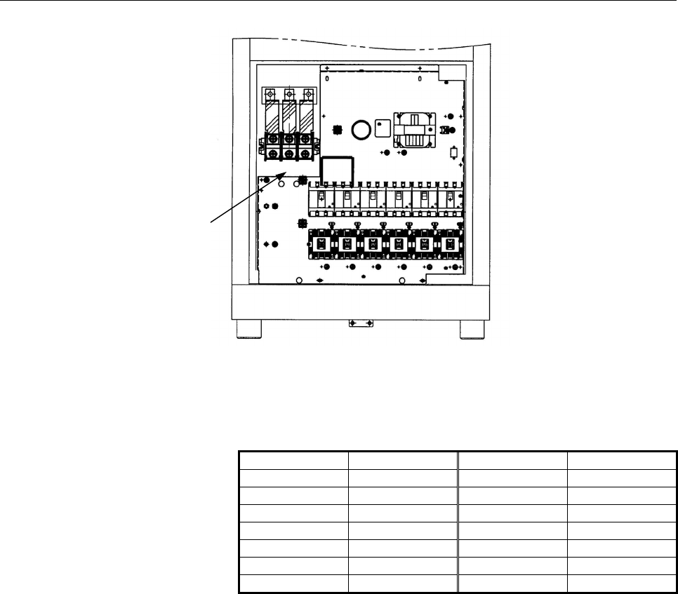
Fig.3.9.1(h) Power cable terminal of C6000-E
(4) CNL1 terminal
B8 PF2 A8 PF1
B7 OFI2 A7 OFI1
B6 A2 A6 A1
B5 EMS2 A5 EMS1
B4 RUN2 A4 RUN1
B3 SHL2 A3 SHL
B2 A2 SC
B1 IB2 A1 IB1
CNL1 pin arrangement (as viewed from the wiring surface)
a) PF1 and PF2
These terminals are for QF1 voltage tripping. Connect
+24 VDC and 0 V to PF1 and PF2, respectively.
b) SHL1 and SHL2
These terminals are for shutter interlocking. Strapping
these terminals enables the shutter to be opened and closed.
Contact current-carrying capacity : At least 1.2 A on 24
VDC
Wire: 1.25 mm2, 25 m or shorter
c) IB1 and IB2
These terminals are for semiconductor laser interlocking.
Strapping these terminals enables the semiconductor laser to
be turned on.
Contact current-carrying capacity: At least 10 mA on 30
VDC
Power cable terminal
L1 L2 L3
Contents Summary of Laser C1000/C2000/C4000/C5000/C6000-Model E Europe Operators manual
- Page 1FANUC LASER C1000-MODEL E FANUC LASER C2000-MODEL E FANUC LASER C4000-MODEL E FANUC LASER C5000-MODEL E FANUC LASER C6000-MODEL E For Europe OPERATOR’S MANUAL B-70314EN/02
- Page 2• No part of this manual may be reproduced in any form. • All specifications and designs are subject to change without notice. In this manual we have tried as much as possible to describe all the various matters. However, we cannot describe all the matters which must not be done, or which cannot be
- Page 3B-70314EN/02 PREFACE PREFACE This manual covers the following models: Model Abbreviation FANUC LASER C1000-MODEL E C1000-E FANUC LASER C2000-MODEL E C2000-E FANUC LASER C4000-MODEL E C4000-E FANUC LASER C5000-MODEL E C5000-E FANUC LASER C6000-MODEL E C6000-E And, these models conform with EMC Direct
- Page 4
- Page 5B-70314EN/02 TABLE OF CONTENTS TABLE OF CONTENTS PREFACE ....................................................................................................p-1 1 OVERVIEW ............................................................................................. 1 1.1 MANUAL CONTENTS ............
- Page 6TABLE OF CONTENTS B-70314EN/02 3.2.1 Lifting Laser Oscillator ..........................................................................................50 3.2.2 Packing ...................................................................................................................50 3.2.3 Environ
- Page 7B-70314EN/02 TABLE OF CONTENTS 5.3.1 Maintenance Panels and Oil Gauge Position........................................................103 5.3.2 Turbo Blower Oil .................................................................................................107 5.3.3 Exhaust Pump Oil................
- Page 8
- Page 9B-70314EN/02 1.OVERVIEW 1 OVERVIEW In this manual, we have tried as for as possible to address all issues. However, space restrictions prevent us from describing everything that must not be done, or which cannot be done, because there are so many possibilities. Therefore, all matters which are not s
- Page 101.OVERVIEW B-70315EN/02 1.1 MANUAL CONTENTS This manual consists of the following chapters and appendixes: 1. OVERVIEW Chapter 1 covers the configuration of the manual, applicable models, related manuals, and provides notes on reading the manual. 2. SAFETY Chapter 2 covers the warnings and precautio
- Page 11B-70314EN/02 1.OVERVIEW 1.2 APPLICABLE MODELS This manual covers the following models: Model Abbreviation FANUC LASER C1000-MODEL E C1000-E FANUC LASER C2000-MODEL E C2000-E FANUC LASER C4000-MODEL E C4000-E FANUC LASER C5000-MODEL E C5000-E FANUC LASER C6000-MODEL E C6000-E -3-
- Page 121.OVERVIEW B-70315EN/02 1.3 RERATED MANUALS The following manuals are available for the FANUC LASER C1000/C2000/C4000/C5000/C6000-MODEL E: DESCREPTIONS B-63192EN CONNECTION MANUAL B-63193EN FANUC Series 16i-LA OPERATOR'S MANUAL B-63194EN MAINTENANCE MANUAL B-63195EN PARAMETER MANUAL B-63200EN FANUC
- Page 13B-70314EN/02 1.OVERVIEW 1.4 FOR SAFE OPERATION This manual contains precautions which must be observed during operation of the laser oscillator, to ensure the operator's safety and prevent damage to the oscillator. Each precaution is indicated by "Warning" or "Caution" according to its severyty. Sup
- Page 141.OVERVIEW B-70315EN/02 1.5 NOTES ON READING THIS MANUAL The functions of a laser machining system depend not only on the laser oscillator, but also on the machine, power magnetics cabinet, servo system, CNC, and operator's panel. This manual describes only the laser oscillator. For a description of
- Page 15B-70314EN/02 2.SAFETY FOR LASER HANDLING 2 SAFETY FOR LASER HANDLING C1000-E, C2000-E, C4000-E, C5000-E and C6000-E produce the rated output laser power of 1000W, 2000W, 4000W, 5000W and 6000W. The CO2 laser beam is the wavelength of 10.6 µm, far infrared, and is invisible to human eyes. The adequat
- Page 162.SAFETY FOR LASER HANDLING B-70314EN/02 2.1 LASER BEAM Fig.2.1(a)-(j) show the position of panel that laser beam exposure is occurred without panel. 1) Potential hazards Laser oscillator emits CO2 laser beam(10.6 µm), which is high power and invisible. • Being directly exposed to the CO2 beam could
- Page 17B-70314EN/02 2.SAFETY FOR LASER HANDLING Fig.2.1(a) Laser beam exposure is occurred without panel as operating (C1000-E) Fig.2.1(b) Laser beam exposure is occurred without panel as operating (C2000-E) Fig.2.1(c) Laser beam exposure is occurred without panel as operating (C4000-E) - 9-
- Page 182.SAFETY FOR LASER HANDLING B-70314EN/02 Fig.2.1(d) Laser beam exposure is occurred without panel as operating (C5000-E) Fig.2.1(e) Laser beam exposure is occurred without panel as operating (C6000-E) - 10 -
- Page 19B-70314EN/02 2.SAFETY FOR LASER HANDLING Fig.2.1(f) The position of laser beam delivery (C1000-E) - 11-
- Page 202.SAFETY FOR LASER HANDLING B-70314EN/02 Fig.2.1(g) The position of laser beam delivery (C2000-E) Fig.2.1(h) The position of laser beam delivery (C4000-E) - 12 -
- Page 21B-70314EN/02 2.SAFETY FOR LASER HANDLING Fig.2.1(i) The position of laser beam delivery (C5000-E) Fig.2.1(j) The position of laser beam delivery (C6000-E) - 13-
- Page 222.SAFETY FOR LASER HANDLING B-70314EN/02 2.2 HIGH VOLTAGE Fig.2.2(a)-(j) show the position of high voltage in oscillator. 1) Potential hazards There is RF voltage of 3 to 4kVo-p in the cabinet of the laser oscillator. There is 200 VAC power in the relay panel, be careful not to touch the high voltag
- Page 23B-70314EN/02 2.SAFETY FOR LASER HANDLING Fig.2.2(a) The position of high voltage in C1000-E (Front, maintenance side). Fig.2.2(b) The position of high voltage in C1000-E (Back side). - 15-
- Page 242.SAFETY FOR LASER HANDLING B-70314EN/02 Fig.2.2(c) The position of high voltage in C2000-E (Front, maintenance side). Fig.2.2(d) The position of high voltage in C2000-E (Back side). - 16 -
- Page 25B-70314EN/02 2.SAFETY FOR LASER HANDLING Fig.2.2(e) The position of high voltage in C4000-E (Front, maintenance side). Fig.2.2(f) The position of high voltage in C4000-E (Back side). - 17-
- Page 262.SAFETY FOR LASER HANDLING B-70314EN/02 Fig.2.2(g) The position of high voltage in C5000-E (Front, maintenance side). Fig.2.2(h) The position of high voltage in C5000-E (Back side). - 18 -
- Page 27B-70314EN/02 2.SAFETY FOR LASER HANDLING Fig.2.2(i)The position of high voltage in C6000-E (Front, maintenance side). Fig.2.2(j)The position of high voltage in C6000-E (Back side). - 19-
- Page 282.SAFETY FOR LASER HANDLING B-70314EN/02 2.3 SAFETY ENCLOSURE (AT YOUR WORK STATION) 1) Potential hazards CO2 beam is delivery from oscillator. Direct or scattered beam is exposed. 2) Safety recommendations Mount the safety enclosure made of acrylic resin which can absorb the laser beam around the w
- Page 29B-70314EN/02 2.SAFETY FOR LASER HANDLING 2.6 HIGH TEMPERATURE Fig.2.6(a)-(j) show the position of high voltage in oscillator. 1) Potential hazards When you touch a part of high temperature, your skin burn. 2) Safety recommendations The pipes of the gas circular system are very a high temperature. Do
- Page 302.SAFETY FOR LASER HANDLING B-70314EN/02 Fig.2.6(a) The position of high temperature in C1000-E (Front, maintenance side). Fig.2.6(b) The position of high temperature in C1000-E (Back side). - 22 -
- Page 31B-70314EN/02 2.SAFETY FOR LASER HANDLING Fig.2.6(c) The position of high temperature in C2000-E (Front, maintenance side). Fig.2.6(d) The position of high temperature in C2000-E (Back side). - 23-
- Page 322.SAFETY FOR LASER HANDLING B-70314EN/02 Fig.2.6(e) The position of high temperature in C4000-E (Front, maintenance side). Fig.2.6(f) The position of high temperature in C4000-E (Back side). - 24 -
- Page 33B-70314EN/02 2.SAFETY FOR LASER HANDLING Fig.2.6(g) The position of high temperature in C5000-E (Front, maintenance side). Fig.2.6(h) The position of high temperature in C5000-E (Back side). - 25-
- Page 342.SAFETY FOR LASER HANDLING B-70314EN/02 Fig.2.6(i) The position of high temperature in C6000-E (Front, maintenance side). Fig.2.6(j) The position of high temperature in C6000-E (Back side). - 26 -
- Page 35B-70314EN/02 2.SAFETY FOR LASER HANDLING 2.7 WARNING LABELS The oscillator uses high voltages and laser beam radiation. Such hazards are indicated with warning labels attached to the positions shown in Fig. 2.7(a) to (j). This section describes the warning labels and their positions. Fig.2.7(a) Warn
- Page 362.SAFETY FOR LASER HANDLING B-70314EN/02 Fig.2.7(c) Warning label positions (C2000-E : front view) Fig.2.7(d) Warning label positions (C2000-E : back view) - 28 -
- Page 37B-70314EN/02 2.SAFETY FOR LASER HANDLING Fig.2.7(e) Warning label positions (C4000-E : front view) Fig.2.7(f) Warning label positions (C4000-E : back view) - 29-
- Page 382.SAFETY FOR LASER HANDLING B-70314EN/02 Fig.2.7(g) Warning label positions (C5000-E : front view) Fig.2.7(h) Warning label positions (C5000-E : back view) - 30 -
- Page 39B-70314EN/02 2.SAFETY FOR LASER HANDLING Fig.2.7(i) Warning label positions (C6000-E : front view) Fig.2.7(j) Warning label positions (C6000-E : back view) - 31-
- Page 402.SAFETY FOR LASER HANDLING B-70314EN/02 <1> Class indication label (C1000-E) <1> Class indication label (C2000-E,C4000-E,C5000-E,C6000-E) - 32 -
- Page 41B-70314EN/02 2.SAFETY FOR LASER HANDLING <2> Warning logotype <3> Access label <4> Label inside the access panel <5> Lifting method label - 33-
- Page 422.SAFETY FOR LASER HANDLING B-70314EN/02 <6> Aperture label <7> Label of non-interlocked protective panel <8> Identification label - 34 -
- Page 43B-70314EN/02 2.SAFETY FOR LASER HANDLING <9> Address label <10> Discharge section label <11> Supply voltage label <12> Label of over-current protective - 35-
- Page 442.SAFETY FOR LASER HANDLING B-70314EN/02 <13> Label of motor and transformer (C1000-E) <13> Label of motor and transformer (C2000-E) <13> Label of motor and transformer (C4000-E) - 36 -
- Page 45B-70314EN/02 2.SAFETY FOR LASER HANDLING <13> Label of motor and transformer (C5000-E,C6000-E) <14> Label of warning light <15> Maintenance label 16> Certification label - 37-
- Page 462.SAFETY FOR LASER HANDLING B-70314EN/02 <17> Short-circuit interrupting capacity of main breaker (C1000-E) <17> Short-circuit interrupting capacity of main breaker (C2000-E,C4000-E) <17> Short-circuit interrupting capacity of main breaker (C5000-E) <17> Short-circuit interrupting capacity of main b
- Page 47B-70314EN/02 2.SAFETY FOR LASER HANDLING <18> Label for regulating the atmospheric gases in the oscillator housing <19> Cooling water and gas maintenance label - 39-
- Page 482.SAFETY FOR LASER HANDLING B-70314EN/02 2.8 HIGH-PRESSURE GAS Do not allow any dangerous or high-pressure gas to get into the oscillator housing. The oscillator cabinet has a hermetic structure (dustproof and drip-proof), it cannot be ventilated easily. Flammable gases such as oxygen can cause a fi
- Page 49B-70314EN/02 2.SAFETY FOR LASER HANDLING 2.9 KEY CONTROL All the laser products have to comply with the various kinds of laser safety regulations, which include the use of key control. For instance, FDA PART 1040 PERFORMANCE STANDARDS FOR LIGHT-EMITTING PRODUCTS, Sec 1040. 10 (f), (4) states: "Each
- Page 502.SAFETY FOR LASER HANDLING B-70314EN/02 2.11 EMERGENCY STOP BUTTON Press the emergency stop button when it is dangerous and breaks down. The oscillator is stopped discharging, gas pressure control and stand by purge state. Use the one with the compulsion dissociation mechanism for the relay used fo
- Page 51B-70314EN/02 2.SAFETY FOR LASER HANDLING 2.13 INAPPOSITE USE OF LASER OSCILLATOR Inapposite use and the result are described in each explanation place. Inapposite major use are described in the following. (1) The gas with different composition and purity from the specification is connected with the
- Page 523.INSTALLATION B-70314EN/02 3 INSTALLATION - 44 -
- Page 53B-70314EN/02 3.INSTALLATION 3.1 CONDITION 3.1.1 Environmental Conditions (1) Ambient +5 to 30°C (2) Temperature drift Max 1.1°C/min (3) Humidity <75% (relative) (4) Vibration Acceleration < 0.05G Amplitude <5mm (5) Atmosphere Free from dust and volatile vapor 3.1.2 Power Source (1) Input power and m
- Page 543.INSTALLATION B-70314EN/02 3.1.3 Laser Gas Supply the laser oscillator with a mixture of gases that satisfy the conditions listed below. (1) Composition ratio and accuracy (For the composition ratio, check the label and specifications of the oscillator.) Gas A Gas B for C1000-E, C2000-E, C4000-E, C
- Page 55B-70314EN/02 3.INSTALLATION 3.1.4 Cooling Water 3.1.4.1 Specification of the cooling water The quality of cooling water is specified in the table below. Use pure water or tap water passed through an ion exchanger. pH (25°C) 6.0 to 8.0 Conductivity (25°C) 200µS/cm or less Standard Chlorine ion Cl- 20
- Page 563.INSTALLATION B-70314EN/02 3.1.4.4 Anticorrosive Add the following anticorrosive to cooling water immediately after installation to prevent problems due to corroding cooling water and to decrease the frequency of replacement of cooling water. Consult the chiller manufacturer for use of the anticorr
- Page 57B-70314EN/02 3.INSTALLATION 3.1.4.6 Antifreezing solution If the chiller is used in a cold district, it should be provided with an antifreezing function. When the air temperature falls, the water supply pump should be kept running. In a very cold district, incorporate a heater into the chiller to pr
- Page 583.INSTALLATION B-70314EN/02 3.2 TRANSPORTATION 3.2.1 Lifting Laser Oscillator In lifting the laser oscillator, be sure to use the four eyebolts screwed into the top surface of the cabinet as shown in the figure. Never lift using only the two bolts. The weight is shown following tables. The permissib
- Page 59B-70314EN/02 3.INSTALLATION Fig.3.2.2(a) Clamp locations (C1000-E) Fig.3.2.2(b) Clamp locations (C2000-E) - 51 -
- Page 603.INSTALLATION B-70314EN/02 Fig.3.2.2(c) Clamp locations (C4000-E) Fig.3.2.2(d) Clamp locations (C5000-E) - 52 -
- Page 61B-70314EN/02 3.INSTALLATION Fig.3.2.2(e) Clamp locations (C6000-E) - 53 -
- Page 623.INSTALLATION B-70314EN/02 3.2.3 Environmental Condition (1) Ambient -20 to 50°C CAUTION Must be completed to drain in the oscillator. If water remain in the oscillator, water freeze during the transportation at cold district. Therefore oscillator is damaged. (2) Humidity <75% (relative) (3) Vibrat
- Page 63B-70314EN/02 3.INSTALLATION 3.3 STORAGE The various kinds of clamps should be used only during the transportation. Especially the clamps used for resonator should be loosened during the storage. Storing the resonator as fixed with the clamps for a long time will cause its distortion. The clamps are
- Page 643.INSTALLATION B-70314EN/02 3.4 Base of oscillator In laser oscillator, the two type of that is the four taps and hole are prepared in the base as shown in the figure for fixing the laser cabinet against the machine base. Fig.3.4(a) Mounting (A) Fig.3.4(b) Mounting (B) Fig.3.4(c) Cabinet base (C1000
- Page 65B-70314EN/02 3.INSTALLATION Fig.3.4(d) Cabinet base (C2000-E, C4000-E) Fig.3.4(e) Cabinet base (C5000-E) - 57 -
- Page 663.INSTALLATION B-70314EN/02 Fig.3.4(f) Cabinet base (C6000-E) - 58 -
- Page 67B-70314EN/02 3.INSTALLATION 3.5 MAINTENANCE AREA The maintenance area of laser oscillator series are shown in the figures below. The customer is requested to prepare adequate space around the laser even for the sides, which are not requested in the figures. Fig.3.5(a) Maintenance area (C1000-E) - 59
- Page 683.INSTALLATION B-70314EN/02 Fig.3.5(b) Maintenance area (C2000-E : Short optical path length type) Fig.3.5(c) Maintenance area (C2000-E : Long optical path length type) - 60 -
- Page 69B-70314EN/02 3.INSTALLATION Fig.3.5(d) Maintenance area (C4000-E : Short optical path length type) Fig.3.5(e) Maintenance area (C4000-E : Long optical path length type) - 61 -
- Page 703.INSTALLATION B-70314EN/02 Fig.3.5(f) Maintenance area (C5000-E) Fig.3.5(g) Maintenance area (C6000-E) - 62 -
- Page 71B-70314EN/02 3.INSTALLATION 3.6 WATER CONNECTION 3.6.1 Chiller Make the cooling water re-circulate in the closed loop using a chiller unit. The cooling requirements of the chiller are as below. (1) Chiller capacity Type Capacity C1000-E > 11KW C2000-E > 22.1KW C4000-E > 44.2KW C5000-E > 55KW C6000-E
- Page 723.INSTALLATION B-70314EN/02 3.6.2 Cooling Water Temperature Throughout the year, set the chiller water temperature to 27°C in general regions and 30°C in humid regions. 3.6.3 Cooling Water Flow Rate The flow rate should be chosen so that the temperature difference between the inlet and outlet of the
- Page 73B-70314EN/02 3.INSTALLATION 3.7 LASER GAS 3.7.1 Gas Bottle Use the gas bottle of the volume of 7m3. Store the necessary number of bottles according to the operation of the laser. 3.7.2 Laser Gas Tubing Laser gas inlet and outlet fittings on laser are female Rc 3/8". (1) Gas inlet of oscillator • Use
- Page 743.INSTALLATION B-70314EN/02 • After installing the pipe, check it for gas leakage, using a liquid leak checker (Gyupoflex : A98L-0001-0856, detecting bubbles caused by leaking gas) or a clamp test1 NOTE Open the valve of the gas cylinder to pressurize the inside of the pipe, then close the valve. Ch
- Page 75B-70314EN/02 3.INSTALLATION 3.8 LASER BEAM Here explanation are given for the convenience of designing machines. 3.8.1 Position and Tolerance of Laser Beam Exit The following figures and attached tables show the positions and tolerances of beam. Fig.3.8.1(a) Beam exit Fig.3.8.1(b) Position of laser
- Page 763.INSTALLATION B-70314EN/02 3.8.2 Beam Divergence The beam divergence for LASER C1000/C2000/C4000/C5000/C6000-MODEL E is less than 2 mrad. 3.8.3 Tolerance of Beam Direction The tolerance of beam direction is ±0.3 degrees. The customer is requested to prepare adjusting mechanism on the machine side t
- Page 77B-70314EN/02 3.INSTALLATION 3.9 ELECTRICAL CONNECTION 3.9.1 NC-to-oscillator connection and power supply cable connection Connect the cables to the laser oscillator as described below. (1) Power cable U (R), V (S), W (T) Recommended power cables (a) If placing the cable in the duct If laying the pow
- Page 783.INSTALLATION B-70314EN/02 (b) If not placing the cable in the duct If not placing the power cable in the duct between the power board and the laser oscillator, you can use a heavy-duty power cord cable. OSC Recommendation Cross Section Diameter Current Type Layout C1000-E 2 4 Core Hitachi Cable :
- Page 79B-70314EN/02 3.INSTALLATION (e) Tightening torque for terminal Tightening torque of mounting screws is as follows. OSC Torque C1000-E 5.5 to 7.5N⋅m C2000-E 15N⋅m C4000-E 15N⋅m C5000-E 8 to 13N⋅m C6000-E 10 to 15N⋅m (2) Ground cable There are two grounding locations. One of the locations is for calss
- Page 803.INSTALLATION B-70314EN/02 Fig.3.9.1(b) Cable connection (C1000-E) Fig.3.9.1(c) Cable connection (C2000-E) Fig.3.9.1(d) Cable connection (C4000-E) - 72 -
- Page 81B-70314EN/02 3.INSTALLATION Fig.3.9.1(e) Cable connection (C5000-E) Fig.3.9.1(f) Cable connection (C6000-E) Fig.3.9.1(g) Location and Signal assignment of CNL1 - 73 -
- Page 823.INSTALLATION B-70314EN/02 L1 L2 L3 Power cable terminal Fig.3.9.1(h) Power cable terminal of C6000-E (4) CNL1 terminal B8 PF2 A8 PF1 B7 OFI2 A7 OFI1 B6 A2 A6 A1 B5 EMS2 A5 EMS1 B4 RUN2 A4 RUN1 B3 SHL2 A3 SHL B2 A2 SC B1 IB2 A1 IB1 CNL1 pin arrangement (as viewed from the wiring surface) a) PF1 and
- Page 83B-70314EN/02 3.INSTALLATION d) A1 and A2 These terminals are for supplying power to the safety box in the laser oscillator and switching on and off the laser oscillator power supply. Connect +24 VDC and 0 V to A1 and A2, respectively. Current-carrying capacity: At least 250 mA e) SC This terminal is
- Page 843.INSTALLATION B-70314EN/02 3.9.2 Safety Interlock The figure shows the safety circuit for each oscillator. Fig.3.9.2(a) Safety Interlock circuit (C1000-E) - 76 -
- Page 85B-70314EN/02 3.INSTALLATION Fig.3.9.2(b) Safety interlock circuit (C2000-E) - 77 -
- Page 863.INSTALLATION B-70314EN/02 Fig.3.9.2(c) Safety interlock circuit (C4000-E) - 78 -
- Page 87B-70314EN/02 3.INSTALLATION Fig.3.9.2(d) Safety interlock circuit (C5000-E) - 79 -
- Page 883.INSTALLATION B-70314EN/02 Fig.3.9.2(e) Safety interlock circuit (C6000-E) - 80 -
- Page 89B-70314EN/02 3.INSTALLATION 3.9.3 EMC Countermeasure (1) Cable shield (for C1000/C2000/C4000/C6000-MODEL E) Install the appended Cable Shield in power cable. Main power cable (220V/200V AC 3φ) is wrapped with CABLE SHIELD and the earth cable of CABLE SHIELD is grounded. In that case, there is no spa
- Page 903.INSTALLATION B-70314EN/02 3.9.4 Inter-unit Connections The C1000-E has an oscillator section and exhaust pump section. Inter-unit connections include 1. vacuum tube connection and 2. power cable connection. Before making connections, check the following: (a) Check for any foreign particles in comp
- Page 91B-70314EN/02 3.INSTALLATION 3.9.4.1 Vacuum tube connection Prepare the following parts: • Pt screwed pipe fittings (elbow) : (included in the fittings kit (A04B-0816-K354)) • Tube : (included in the connection kit (A04B-0816-K130)) • Union : (included in the fittings kit (A04B-0816-K354)) • Adapter
- Page 924.FUNCTIONS B-70314EN/02 4 FUNCTIONS - 84 -
- Page 93B-70314EN/02 4.FUNCTIONS 4.1 OUTLINE Fig. 4.1 shows an outline of the structure of the oscillator. Fig.4.1 Outline of structure (1) Laser resonator The resonator consists of an output coupler, a rear mirror, folding mirrors, discharge tubes, a power sensor unit, etc. Several discharge tubes are conn
- Page 944.FUNCTIONS B-70314EN/02 (3) Laser gas circulating system A gas circulating system is configured by connecting the resonator and the fan (turbo blower) with a circulating pipe. Laser gas runs through the discharge tubes at a speed of 200 m/s or higher. In this circulating system, a water-cooled heat
- Page 95B-70314EN/02 4.FUNCTIONS 4.2 INTERNAL STRUCTURE This section describes the internal structure of the oscillator more specifically. Fig.4.2(a) to (j) are internal structural drawing. Fig.4.2(a) Internal structural drawing (C1000-E : front view) Fig.4.2(b) Internal structural drawing (C1000-E : rear v
- Page 964.FUNCTIONS B-70314EN/02 Fig.4.2(c) Internal structural drawing (C2000-E : front view) Fig.4.2(d) Internal structural drawing (C2000-E : rear view) - 88 -
- Page 97B-70314EN/02 4.FUNCTIONS Fig.4.2(e) Internal structural drawing (C4000-E : front view) Fig.4.2(f) Internal structural drawing (C4000-E : rear view) - 89 -
- Page 984.FUNCTIONS B-70314EN/02 Fig.4.2(g) Internal structural drawing (C5000-E : front view) Fig.4.2(h) Internal structural drawing (C5000-E : rear view) - 90 -
- Page 99B-70314EN/02 4.FUNCTIONS Fig.4.2(i) Internal structural drawing (C6000-E : front view) Fig.4.2(j) Internal structural drawing (C6000-E : rear view) - 91 -
- Page 1004.FUNCTIONS B-70314EN/02 (1) Output coupler A transmitting/reflecting mirror, which outputs the laser beam after it, has been amplified inside the resonator. The output coupler consists of a ZnSe (zinc selenide) substrate with a curvature on the surface and coated with dielectric. ZnSe is highly tox
- Page 101B-70314EN/02 4.FUNCTIONS (9) Matching box The matching box contains a matching circuit, which ensures that power is effectively input to the discharge tubes. (10) Turbo blower This fan circulates the laser gas in the gas circulating system at high speed. It rotates at a high speed of 60,000 revoluti
- Page 1024.FUNCTIONS B-70314EN/02 (18) Exhaust control unit (C2000-E, C4000-E) The exhaust control unit is capable of controlling the flow rate of the gas to be exhausted. (19) Exhaust pump This pump is used to vacuum-exhaust laser gas from the gas circulating system such that its pressure falls to that used
- Page 103B-70314EN/02 4.FUNCTIONS (27) Interface PCB This PCB communicates with the CNC via the FANUC I/O LINK (serial interface). (28) Stabilized power supply This unit supplies DC power (24 VDC) to the interface PCB and various units. (29) Dew sensor This sensor is mounted to the output coupler holder to m
- Page 1044.FUNCTIONS B-70314EN/02 4.3 LASER OSCILLATION SEQUENCE SEQ 0 PURGE = 0 POWER OFF state LRDY = 0 PTLP = 0 LSTR = 0 CNC POWER = ON CNC POWER = OFF SEQ 10 PURGE = 1 LRDY = 0 INITIAL PTLP = 0 LSTR = 0 (WAIT=1) (START KEY) (START KEY) RUN = ON RUN = OFF SEQ 20 (WAIT=1) PURGE = 0 LRDY = 1 READY OF PTLP =
- Page 105B-70314EN/02 4.FUNCTIONS [SQ20] READY OF DISCHARGING state When oscillator start switch is turned on, evacuation is carried on and then gas pressure control begins. When the gas pressure reaches the set pressure, the discharge preparation completion state (LRDY) is set to enable the discharge start
- Page 1064.FUNCTIONS B-70314EN/02 4.4 LASER PROCESSING MACHINE SYSTEM The material processing machine using FANUC LASER C1000/C2000/C4000/C5000/C6000-MODEL E is usually composed in the configuration shown in the figure. In the figure the rectangular parts of the solid line are FANUC products. In the below ea
- Page 107B-70314EN/02 4.FUNCTIONS (4) Guide laser (Laser diode) A diode laser is used for coarse-control of the optical system axis after a light beam is output from the oscillator. This laser can also be used to identify the point to be machined. (5) Assist gas unit In laser material processing the injectio
- Page 1085.MAINTENANCE B-70314EN/02 5 MAINTENANCE In FANUC LASER C1000/C2000/C4000/C5000/C6000-MODEL E, periodic inspection items have been reduced, and adjustments have been made easy. To keep the oscillator in a satisfactory operating condition over a long period, however, it is necessary to carry out peri
- Page 109B-70314EN/02 5.MAINTENANCE 5.1 DAILY INSPECTION Table 5.1 lists daily inspection items. Inspect the FANUC LASER C1000/C2000/C4000/C5000/C6000-MODEL E according to this table. When parts (including oil) have been used for a prescribed period, replace them quickly. Table 5.1 Daily inspection items for
- Page 1105.MAINTENANCE B-70314EN/02 5.2 PERIODIC MAINTENANCE The laser oscillator contains consumables that must be replaced periodically. Table 5.2(a) or (b) lists such consumables and the related periodic maintenance work. Perform periodic maintenance as well as daily inspection described in Section 5.1 by
- Page 111B-70314EN/02 5.MAINTENANCE 5.3 DETAILS OF MAINTENANCE When opening the panels and doors during maintenance, keep the power turned off. 5.3.1 Maintenance Panels and Oil Gauge Position Be sure to open the panel indicated in slash in Fig.5.3.1(a) to (e) before replacing oil or the filter during daily m
- Page 1125.MAINTENANCE B-70314EN/02 Fig.5.3.1(d) Maintenance panel (C5000-E) Fig.5.3.1(e) Maintenance panel (C6000-E) The locations of the oil gauges are shown in Fig.5.3.1(f) to (j) Fig.5.3.1(f) Oil gauge of turbo blower and exhaust pump (C1000-E) - 104 -
- Page 113B-70314EN/02 5.MAINTENANCE A B Fig.5.3.1(g) Oil gauge of turbo blower and exhaust pump (C2000-E) A B Fig.5.3.1(h) Oil gauge of turbo blower and exhaust pump (C4000-E) - 105 -
- Page 1145.MAINTENANCE B-70314EN/02 B A A Fig.5.3.1(i) Oil gauge of turbo blower and exhaust pump (C5000-E) A A B Fig.5.3.1(j) Oil gauge of turbo blower and exhaust pump (C6000-E) - 106 -
- Page 115B-70314EN/02 5.MAINTENANCE 5.3.2 Turbo Blower Oil (1) Check method Check the amount of oil in the turbo blower while referring to the figure below. The oil level should be between graduations H and L. Fig.5.3.2(a) Turbo blower oil gauge NOTE This check should be made when the oscillator is at a rest
- Page 1165.MAINTENANCE B-70314EN/02 3) Clean the oil inlet, hexagonal-head screw of the oil inlet, and O-ring by wiping with a clean cloth or paper. Ensure that these parts are completely free of dust. If the oil is contaminated with dust, the turbo blower may fail. Set the O-ring in the groove around the he
- Page 117B-70314EN/02 5.MAINTENANCE NOTE 1 Use turbo blower oil within an expiratio date. 2 If the container is opened, use the oil in that within 6 months. 3 Use a clean supply tube when you pour the oil and be careful not to put dust in turbo blower. 4 Keep away from direct sunlight and keep in a cool, dry
- Page 1185.MAINTENANCE B-70314EN/02 6) After the oil has been drained up, close the cock. 7) Supply 1.8 liters of new oil through the oil inlet, while watching the oil gauge. 8) Attach the oil inlet plug. 9) Put the maintenance panel back in place, and turn on the power. Fig.5.3.3(b) Exhaust pump oil check p
- Page 119B-70314EN/02 5.MAINTENANCE 5.3.4 Exhaust Pump Filter (1) Replacement method Replace the filter every 3000 hours, or when the exhaust power has degraded. If the filter gets clogged, the pump output becomes low. Fig. 5.3.4 shows where the filter of a exhaust pump is located. 1) Stop the oscillator, an
- Page 1205.MAINTENANCE B-70314EN/02 5.4 AGING If the machine has not been unused for an extended period of time (three days or longer) or if the laser gas circulatory system is exposed to the atmosphere (after, for example, turbo blower oil replacement), aging is required. Aging refers to heating the dischar
- Page 121B-70314EN/02 5.MAINTENANCE 5.4.2 Aging method (1) When the laser gas circulating system has been opened to the atmosphere, perform discharge aging by using the automatic aging function. (a) Set bit 6 (EGE) of parameter No. 15008 to 1 to enable the automatic aging function. (b) Check and set the foll
- Page 1225.MAINTENANCE B-70314EN/02 5.5 MAINTENANCE PARTS To procure consumables, contact the machine builder of FANUC service center, and tel the applicable specification number listed below. 5.5.1 Spare Parts (1) Consumable parts Item Specification 1 Turbo blower oil kit A04B-0800-K326 2 Exhaust pump oil A
- Page 123B-70314EN/02 5.MAINTENANCE 5.5.2 Maintenance Tools Following tools are recommended for maintenance. (1) Equipment Equipment Condition Application AC voltmeter Accuracy: ±2% For measuring AC power DC voltmeter Full scale: 10V, 30V For measuring DC Accuracy: ±2% power Digital voltmeter Full scale: 10V
- Page 1246.TROUBLESHOOTING B-70314EN/02 6 TROUBLESHOOTING - 116 -
- Page 125B-70315EN/02 6.TROUBLESHOOTING 6.1 TROUBLESHOOTING PROCEDURE After identifying the following items, call the FANUC service center. In some cases, a symptom is not actually a fault in the oscillator, although it looks a fault. So, check it with the following sections. 1. Symptoms 1. State of operatio
- Page 1266.TROUBLESHOOTING B-70314EN/02 6.2 RESPONDING TO ALARM MESSAGES ON THE SCREEN See a list of alarms in an appendix at the end of this manual. ALM No.4061 A/D CONVERTER–1 Alarm output condition This alarm is issued when the A/D converter 1 on the IF PCB does not return the conversion completion signal
- Page 127B-70315EN/02 6.TROUBLESHOOTING ALM No.4063 RF POWER SUPPLY / LASER GAS This message appears when the laser power supply unit becomes abnormal or performs protective operation. The power supply unit performs protective operation even if an error occurs in other than the power supply unit itself. This
- Page 1286.TROUBLESHOOTING B-70314EN/02 No. Check item Cause of trouble, Solution 6 Checking the 1) Check whether the laser gas composition is laser gas correct, and replace the laser gas with the one that satisfies the specifications. 2) Check for gas leakage in the external laser gas piping, investigate th
- Page 129B-70315EN/02 6.TROUBLESHOOTING No. Phenomenon Presumption cause 6 The RF voltage of all the units is high and Internal leakage of the laser power is low. The discharge is oscillator tends to disappear. (DCI alarm) Internal leakage of Even though the purge is repeatedly water of the oscillator perfor
- Page 1306.TROUBLESHOOTING B-70314EN/02 See the following table, and check the operation status. [Open] command [Close] command DGN No.973 #0=1 DGN No.973 #0=0 Shutter open state signal 1 1 0 0 1 1 0 0 DGN No.961 #4 Shutter close state signal 0 1 0 1 0 1 0 1 DGN No.961 #5 Normal/Abnormal O X X X X X X O No.
- Page 131B-70315EN/02 6.TROUBLESHOOTING No. Cause of trouble Solution 4 Leakage in vacuum Locate the leakage, and replace the system or water defective part. leakage 5 The gas flow control Adjust the gas flow control valve to obtain valve is closed the specified gas flow rate. 6 Matching box Replace the matc
- Page 1326.TROUBLESHOOTING B-70314EN/02 Alarm output condition This alarm is issued when the actual laser output is in one of the following conditions at the time of beam output: (1) The actual laser output is higher than the average command power (power × duty) by more than the value set in parameter No. 15
- Page 133B-70315EN/02 6.TROUBLESHOOTING No. Cause of trouble Solution 3 Anomaly of power unit of IF See Maintenance manual for details of the PCB (A16B-2100-0142) normal supply voltage. If the allowable voltage range is exceeded, replace the IF PCB. 4 Laser oscillator main circuit Check whether the main circ
- Page 1346.TROUBLESHOOTING B-70314EN/02 No. Cause of trouble Solution 2 Poor connection Check the connection between the assist gas supply unit and CNC. ALM No.4072 CHILL FLOW This alarm appears when the water shortage takes place. Alarm output condition This alarm is issued if the cooling water amount signa
- Page 135B-70315EN/02 6.TROUBLESHOOTING No. Cause of trouble Solution 1 Tool low supply Adjust the secondary pressure at the regulator on pressure of laser the gas cylinder so that the pressure of laser gas gas supplied to the laser oscillator is 0.175MPa±0.025MPa (rating) as measured at the entry of the osc
- Page 1366.TROUBLESHOOTING B-70314EN/02 ALM No.4076 LASER POWER DOWN This alarm is issued if the monitored laser output is lower than the specified laser output by at least the allowable value. Alarm output condition This alarm is issued when the actual laser output level is lower than the average command po
- Page 137B-70315EN/02 6.TROUBLESHOOTING ALM No.4077 ABSORBER TEMP. This alarm is issued if the temperature absorber exceeds the allowable value. In the usual operation, this beam absorber is irradiated by the rated output only during the laser output compensation conducted after the start of the oscillator.
- Page 1386.TROUBLESHOOTING B-70314EN/02 No. Cause of trouble Solution 1 Anomaly of parameter Check whether the values of PRM NO. setting of gas pressure 15000/bit1,15244,15245,15246 are set as control indicated in the attached parameter table. If a different value is set, set the value specified in the data
- Page 139B-70315EN/02 6.TROUBLESHOOTING Alarm output condition Turning the oscillator start switch on causes exhaust to start. This alarm is issued if the laser gas pressure does not reach the setting of parameter No. 15240 when the time set in parameter No.15259 has elapsed. Related parameters PRM.15240 Eva
- Page 1406.TROUBLESHOOTING B-70314EN/02 No. Cause of trouble Solution 5 Anomaly of exhaust If the above checks do not reveal any pump abnormality, the performance of the exhaust pump has deteriorated. Check the following items. 1) Check whether specified oil is provided at an appropriate level. Supply specif
- Page 141B-70315EN/02 6.TROUBLESHOOTING No. Cause of trouble Solution 3 Anomaly of supply laser Adjust the secondary pressure at the gas pressure regulator on the gas cylinder so that the pressure of laser gas supplied to the laser oscillator is 0.175MPa±0.025MPa (rating) as measured at the entry of the osci
- Page 1426.TROUBLESHOOTING B-70314EN/02 Alarm output condition This alarm is issued when the power compensation coefficient exceeds the power compensation limit during execution of power compensation. Power compensation coefficient = (Pc/Pa) × 1024 Pc : Parameter No. 15200 or 15201 Pa : Actual laser output R
- Page 143B-70315EN/02 6.TROUBLESHOOTING ALM No.4088 LASER VOLTAGE DOWN This alarm is issued, if the voltage applied to the discharge tube drops largely. Alarm output condition 1) Immediately before the oscillation ready state (LSTR) is established, the RF voltage of the power supply with the smallest number
- Page 1446.TROUBLESHOOTING B-70314EN/02 ALM No.4090 LASER NOT GENERATE This alarm is issued if an attempt is made to radiate a laser beam when the laser is not in the oscillation ready (LSTR) state. Alarm output condition This alarm is issued if the oscillation ready (LSTR) state is not established during be
- Page 145B-70315EN/02 6.TROUBLESHOOTING Alarm output condition When the integral value of gas pressure control is preset and the pressure is increased from the from the gas pressure at the start of discharge to the gas pressure during oscillation, this alarm is issued if the actual gas pressure has not incre
- Page 1466.TROUBLESHOOTING B-70314EN/02 No. Cause of trouble Solution 1 Invalid parameter Check whether the values of PRM Nos. 15240, setting 15241, and 15242 are set as indicated in the attached parameter table. If a different value is set, set the value specified in the data sheets. 2 Anomaly of turbo Repl
- Page 147B-70315EN/02 6.TROUBLESHOOTING ALM No.4105 TURBO TEMP. 1 This alarm is issued, if the temperature of the turbo blower motor winding becomes higher than the permissible level. Alarm output condition This alarm is issued if the turbo temperature signal becomes "0" after the start of the oscillator and
- Page 1486.TROUBLESHOOTING B-70314EN/02 No. Cause of Solution trouble 4 Insufficient turbo When the temperature of the turbo blower motor blower cooling section is high, check whether the cooling water path is clogged. This alarm is issued also when the cooling water in the turbo blower becomes insufficient.
- Page 149B-70315EN/02 6.TROUBLESHOOTING ALM No.4124 OVER COOL The oscillator has a low temperature sensor on the side of resonator plate to measure the temperature of cooling water. Alarm output condition This alarm is issued if the cooling water temperature becomes less than 20℃ after laser warm-up driving.
- Page 150
- Page 151APPENDI
- Page 152
- Page 153B-70314EN/02 APPENDIX A.EXTERNAL VIEW OF LASER OSCILLATOR A EXTERNAL VIEW OF LASER OSCILLATOR Fig.A(a) External view of laser oscillator (C1000-E) - 145 -
- Page 154A.EXTERNAL VIEW OF LASER OSCILLATOR APPENDIX B-70314EN/01 Fig.A(b) External view of laser oscillator (C2000-E : short optical path length type) Fig.A(c) External view of laser oscillator (C2000-E : long optical path length type) - 146 -
- Page 155B-70314EN/02 APPENDIX A.EXTERNAL VIEW OF LASER OSCILLATOR Fig.A(d) External view of laser oscillator (C4000-E : short optical path length type) Fig.A(e) External view of laser oscillator (C4000-E : long optical path length type) - 147 -
- Page 156A.EXTERNAL VIEW OF LASER OSCILLATOR APPENDIX B-70314EN/01 Fig.A(f) External view of laser oscillator (C5000-E) Fig.A(g) External view of laser oscillator (C6000-E) - 148 -
- Page 157B-70314EN/02 APPENDIX B.SPECIFICATIONS B Item SPECIFICATIONS Contents Model C1000-E C2000-E C4000-E C5000-E C6000-E Principle RF discharge excited fast axial gas flow CO2 laser Oscillator and Structure Vacuum pump Integrated type (oscillator and power supply) unit separated Rated laser output 1,000
- Page 158C.ERROR CODE LIST APPENDIX B-70314EN/02 C Number ERROR CODE LIST Message Alarm handling level 4061 A/D CONVERTER–1 Up to a purge 4062 A/D CONVERTER–2 Up to a purge 4063 RF POWER SUPPLY / LASER GAS Up to LRDY 4065 SHUTTER ACTION Up to LRDY 4066 DISCHARGING Up to LRDY 4067 LASER CABINET OH Up to a pur
- Page 159B-70314EN/02 APPENDIX C.ERROR CODE LIST PURGE : Completion state RESET ALARM? MONITOR RUN ON LRDY : Discharge ready state ALARM MONITOR RESET ALARM? 1 HV ON= ALARM MONITOR ON MONITOR 2 LSTR : Discharge ready /TREAT Alarm treatment of FANUC LASER C1000/C2000/C4000/C5000/C6000-MODEL E - 151 -
- Page 160D.FANUC SERVICE NETWORK APPENDIX B-70314EN/02 D FANUC LTD FANUC SERVICE NETWORK Headquarters and Service division: Oshino-mura, Yamanashi Prefecture, 401-0597 JAPAN Phone: 555-84-5555 Fax: 555-84-5512 Country Code: 81 SERVICE LOCATION OF EUROPE AREA Location Service Representative Service area Paris
- Page 161B-70314EN/02 APPENDIX E.GLOSSARY E Name GLOSSARY Meaning Part of the protective housing or enclosure that, when removed or moved, will permit Access panel exposure to laser radiation or collateral radiation beyond an allowable value. AEL : Accessible Maximum accessible emission level set up for each
- Page 162E.GLOSSARY APPENDIX B-70314EN/02 Name Meaning Maximum radiation power or maximum radiation energy per pulse that a laser product Maximum output outputs in all directions where there is a hazard of exposure in view of operational capacity in every area at any point of time after the production of the
- Page 163B-70314EN/02 INDEX INDEX Gas Pipe ..........................................................................65 GLOSSARY..................................................................153 AGING.......................................................................... 112 Aging method...........
- Page 164INDEX B-70314EN/02
Packing............................................................................ 50 PERIODIC MAINTENANCE ...................................... 102 Plumbing ......................................................................... 64 Position and Tolerance of Laser Beam Exi
- Page 165Revision Record FANUC LASER C1000/C2000/C4000/C5000/C6000-MODEL E MAINTENANCE MANUAL (B-70314EN) 02 Jul., 2005 - Addition of LASER C5000-E and C6000-E 01 May, 2001 Edition Date Contents Edition Date Contents
- Page 166