Series 16i/18i/21i Additional Manual Page 7
Additional Manual
Edit
Apprv. Desig.
Sheet
Title
Draw
No.
Date
Design
Descri
p
tion
Date
FANUC Series 16i /18i /21i – B, 18i – MB5
Optimal acc/dec decision at positioning
Specification
Oct.4.2004
7/9
A-79261E
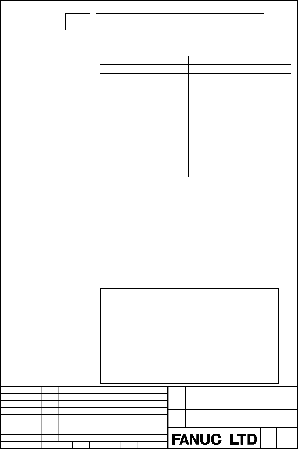
1620
Time constant T or T
1
used for linear acceleration/deceleration or bell-
shaped acceleration/deceleration in rapid traverse for each axis
[Data type] Word axis
[Unit of data] msec
[Valid data range]
Type of acc./dec. in rapid traverse Valid data range
Non linear type 0 ~ 4000msec
Linear type
(with a constant inclination)
0 ~ 4000msec
Linear type
(with a constant time)
0 ~ 4096msec
• Total setting time of each axis
• In case of bell-shaped acc./dec.,
total setting time of (T
1
+ T
2
)
should be less than 4096msec.
Linear type
(with a constant time)
In case that this option is applied.
• Linear type acc./dec.
0 ~ 2048msec
• Bell-shaped type acc./dec.
T
1
= 0 ~ 1536msec
T
2
= 0 ~ 512msec
Specify a time constant used for acceleration/deceleration in rapid traverse.
(When the optional function of bell-shaped acceleration/deceleration in rapid
traverse is provided, bell-shaped acceleration/deceleration is applied in rapid
traverse. If the function is not provided, linear acceleration/deceleration is
applied.)
(1) When bell-shaped acceleration/deceleration in rapid traverse is provided, set
this parameter to time constant T
1
used in bell-shaped
acceleration/deceleration in rapid traverse, and set parameter No.1621 to
time constant T
2
.
(2) When bell-shaped acceleration/deceleration in rapid traverse is not provided,
specify a time constant used in linear acceleration/deceleration.
Note
1 When parameter No.1621 (time constant T
2
used for bell-shaped
acceleration/deceleration in rapid traverse) is set to 0, linear
acceleration/deceleration is applied in rapid traverse even if bell-
shaped acceleration/deceleration in rapid traverse is provided. In
this case, this parameter stands for a time constant used in
linear acceleration/deceleration in rapid traverse.
2 According to the setting of time constant, the axis may move at a
little slower speed than the rapid traverse speed during a certain
time when acceleration ends. In order to avoid this phenomenon,
please set the multiple of 8 to this parameter.
Contents Summary of Series 16i/18i/21i Additional Manual
- Page 1FANUC Series 16i /18i /21i – MB FANUC Series 18i – MB5 Optimal acc/dec decision at positioning Specification - Contents - 1 OUTLINE............................................................................................................................ 2 2 SPECIFICATIONS..........................
- Page 21 Outline Usually, the linear type positioning (G00) is used at the rapid traverse of an extract motion when machining, especially drilling and tapping machining, on the tilted plane. At the linear type positioning, in order to keep the straight line, it is necessary to use a constant time acc./dec.
- Page 32 Specifications When the following parameter settings, an acceleration/deceleration with keeping the straight line is done at an optimal time constant calculated by the rapid traverse feedrate and commanded movement value for each axis even if the different time constant is set for each axis. Examp
- Page 4(2) In case that this function is valid. At every rapid traverse block, the time constant of the axis specified by the program is automatically calculated to use the maximum acceleration ability of each axis, and the time constants are changed for the axes with parameter LRTx (No.1610#3)=1. Therefor
- Page 5And during AI/AI nano high precision contour control and 5-axis machining function with RISC processor, when the rapid traverse with acc./dec. after interpolation (parameter FRP (No.19501#5)=0) is used, it is not possible to use linear type positioning with a constant time. In this case, please use
- Page 63 Parameters #7 #6 #5 #4 #3 #2 #1 #0 1610 LRT [Data type] Bit axis LRTx Optimal acc./dec. decision at positioning is 0 : Invalid. 1 : Valid. Note 1. This parameter is valid when both parameter LRP (No.1401#1) and RPT (No.1603#4) are “1”. 2. Set this parameter for all axes, which are commanded at G00
- Page 7Time constant T or T1 used for linear acceleration/deceleration or bell- 1620 shaped acceleration/deceleration in rapid traverse for each axis [Data type] Word axis [Unit of data] msec [Valid data range] Type of acc./dec. in rapid traverse Valid data range Non linear type 0 ~ 4000msec Linear type 0
- Page 8Set the value when the rapid traverse override is 100%. The value of T1 is determined from the torque of motor. Usually set the value of T2 to 24ms or 32ms. Time constant T2 used for bell-shaped acceleration/deceleration in rapid 1621 traverse for each axis [Data type] Word axis [Unit of data] msec
- Page 94 Notes (1) This function is invalid for the following feeds. - Cutting feed - Manual rapid traverse - Positioning command of manual numerical control - Positioning command of PMC axis control - Positioning command of chopping function (2) This function is invalid when the following function is atta