Series 16i/18i/21i/160i/180i/210i-Model A Startup Guide Page 31
Startup Guide
B-63003EN-2/01 Chapter 1 Assembling the 16i/18i/21i 1 - 27
1
Connecting the E-Stop and Main Power Control Signal
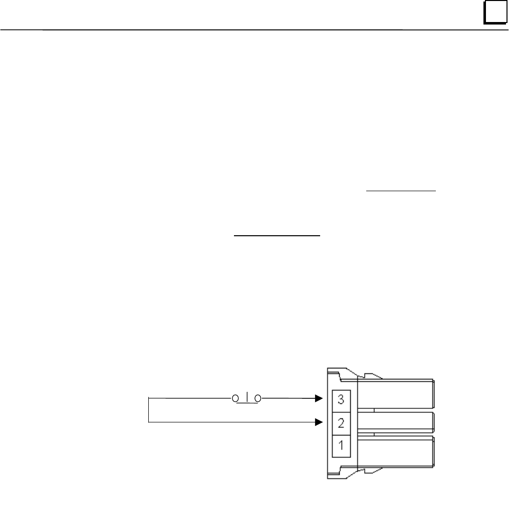
Connecting the machine emergency stop
Figure 1-13 below illustrates the connection of the machine emergency stop to the power
supply module. You must supply the cable for this connection. Connectors are supplied with
the servo amplifier.
1. Locate the 3-pin connector identified by FANUC part #
A02B-0120-K321
.
2. Connect the machine emergency stop device across pins 2 and 3 of the connector
using a normally closed contact. Assemble the connector just like you see it in the
diagram below using a 16 gauge (1.25 mm
2
) wire.
3
.
Connect the wired connector into the slot labeled
CX4 ESP
on the face of the power
supply module.
Note
If a normally closed contact is not connected between pins 2 and 3 on
connector
CX4 ESP
, the amplifier will not energize the motor and an alarm
will be initiated. If no E-stop switch is used, you must make this connection
with a wire jumper.
Figure 1 - 13. Connecting the machine emergency stop signal
+24V
Machine E-STOP Device(s)
Normally Closed
*ESP
CX4 ESP
connector pin layout
Contents Summary of Series 16i/18i/21i/160i/180i/210i-Model A Startup Guide
- Page 1GE Fanuc Automation Computer Numerical Control Products Series 16i / 18i / 160i / 180i – Model A Series 21i / 210i – Model A Startup Guide B-63003EN-2/02 May 2000
- Page 2Preface Thank you for choosing the GE Fanuc i-series for your precision machine tool control applications. Before you begin assembling the control system, please take your time to unpack the control components while keeping the following things in mind: • Hold on to all documentation and shipping pa
- Page 3Contents Chapter 1 Assembling the 16i/18i/21i ................................................................................................................. 1-1 Section 1 Layout of Connectors ...................................................................... 1-2 The 16i/18i/21i Control ......
- Page 4Contents Machine Control .................................................................................................................... 3-2 The Ladder Diagram .............................................................................................................. 3-3 PMC Addresses.......
- Page 5Chapter Assembling the 16i/18i/21i 1 This chapter describes power connections, grounding requirements, and the essential cabling between the separate devices in a 16i/18i/21i control system. Please remember to keep in mind the following guidelines while assembling your system: • Always make sure con
- Page 61 Section 1 Layout of Connectors Before beginning, take time to familiarize yourself with the connector layouts on the next several pages. It might help to make copies and spread them out in front of you to keep from having to constantly flip back and forth through the pages. The 16i/18i/21i Control
- Page 71 Bottom Side View Figure 1-2 below identifies the connectors as seen from the bottom of the control. As you can see, the connector labeled COP10A is hidden behind the yellow casing on the control and may be tricky to find. LCD - front side of control Figure 1 - 2. Layout of connectors as seen from
- Page 81 The Servo Power Supply Module Figure 1-3 below identifies the connectors located on the front panel of a typical power supply module: L+ L- CX1A CX1B CX2B CX2A JX1B CX3 CX4 MCC ESP L1 L2 L3 Figure 1 - 3. Layout of connectors on the face of a typical power supply module 1-4 16i/18i/21i Startup Guid
- Page 91 The Servo Amplifier Module Figure 1-4 below identifies the connectors located on the front panel of a 3-axis servo amplifier module. GE Fanuc servo amplifiers also come in 1-axis and 2-axis models. L+ L- CX2B CX2A JX5 JX1A JX1B ENC1 JF1 ENC2 JF2 ENC3 JF3 COP10B COP10A UL VL UM VM UN VN WL WM WN Fi
- Page 101 The Spindle Amplifier Module Figure 1-5 below identifies the connectors located on the front panel of a typical spindle amplifier module : L+ L- CX1A CX1B CX2B CX2A JX4 JX1A JX1B JY1 JA7B JA7A JY2 JY3 JY4 JY5 L1 L2 L3 Figure 1 - 5. Layout of connectors on the face of a typical spindle amplifier 1-
- Page 111 I/O Unit Model A The Model A I/O unit consists of a base unit, interface module, and I/O modules. Five-slot and ten-slot base units are available as well as vertical and horizontal modules. Figure 1-6 below identifies the different units and the connectors located on the interface module. Interfac
- Page 121 GE Fanuc Operator’s Panel for i-Series Figure 1-7a to 1 – 7e below show the font panel of the main and sub panels for i-series. ON and OFF push-buttons are provided to switch 24V DC power for the control and other machine devices. Figure 1 - 7a. GE Fanuc Main Panel B A02B-0236-C231 Figure 1 - 7b.
- Page 131 Figure 1 - 7d. GE Fanuc Main Panel B + Sub Panel B Figure 1 - 7e. GE Fanuc Main Panel B + Sub Panel C B-63003EN-2/01 Chapter 1 Assembling the 16i/18i/21i 1-9
- Page 141 Section 2 Connection Diagram The block diagram below is meant to give to you an overall perspective of the main connections involved in a GE Fanuc 16i/18i/21i machine tool control system. Although it illustrates typical connections encountered in most applications, this diagram does not address ev
- Page 151 Section 3 Making the Connections To make this section easier to read, all part numbers have been underlined and all connector names written in bold. Connecting the Control to the MDI Unit The MDI unit is the manual data input device. Basically, it is the keyboard used to input data such as program
- Page 161 Power Connections to the Power Supply Module Connecting the 3φ φ motor power line Follow this procedure to connect power to the power supply module: 1. You must supply the cable to connect 200V AC to the power supply module. See Table 1-1 below to determine the required cable gauge for your power
- Page 171 Connecting the control power to the power supply module In order to connect 1φ 200V AC to the power supply module, follow these steps: 1. Locate the cable you are using to connect control power to the power supply module. This connection requires a 16 gauge (1.25 mm2) wire. 2. Locate the 3-pin con
- Page 181 Connecting the Control to the Servo Amplifiers The control is connected to the servo amplifiers by a single optical cable known as the FANUC Serial Servo Bus (FSSB). There is only one connection between the control and the servo amplifiers regardless of the number of controlled axes. Follow this p
- Page 191 Figure 1 - 82. The optical cable for servo amplifier connections B-63003EN-2/01 Chapter 1 Assembling the 16i/18i/21i 1 - 15
- Page 201 Connecting the Control to the Spindle Amplifiers We will discuss the serial spindle connection in this startup guide. If your setup involves an analog spindle, please refer to: Chapter 7.8 in the 16i /18i / 160i / 180i - Model A Connection Manual Chapter 6.2 in the 21i / 210i - Model A Connection
- Page 211 Connecting the Power Supply Module to the Amplifiers The Module Interface Connection The modules are consecutively attached, or “daisy chained”, to one another through the module interface connectors (JX..B resp. CX..B for output and JX..A resp. CX..A for input) located on each power supply module
- Page 221 The 200V AC Connection to the Spindle Amplifiers Note Before you continue, remember that this following connection is only made between the power supply module and connecting spindle amplifier modules. The servo amplifier does not require this connection. 1. The cable LX660-2077-T202/L… connects t
- Page 231 Connecting the Motor Encoder to the Servo Amplifier To connect the motor encoder to the servo amplifier, follow this procedure: 1. Remove the plastic protective cap from the connector on the motor and locate the cable for your motor. Look up your encoder cable part # on the table below Table 1 - 2
- Page 241 1. Find the cable which connects the motor to the servo amplifier. Look up your cable part on the table below: Table 1 - 3. Cross reference of motor power cables GE Fanuc Cables Description Application LX660-8077-T200/L3R003 3m LX660-8077-T200/L4R003 4m LX660-8077-T200/L5R003 5m LX660-8077-T200/L6
- Page 251 GE Fanuc Cables Description Application LX660-8077-T202/L3R003 3m LX660-8077-T202/L4R003 4m LX660-8077-T202/L5R003 5m LX660-8077-T202/L6R003 6m LX660-8077-T202/L7R003 7m LX660-8077-T202/L8R003 8m Power cable for Connection LX660-8077-T202/L10R03 10m Servo Power between Alpha amplifier LX660-8077-T
- Page 261 GE Fanuc Cables Description Application LX660-8077-T205/L3R003 3m LX660-8077-T205/L4R003 4m LX660-8077-T205/L5R003 5m LX660-8077-T205/L6R003 6m LX660-8077-T205/L7R003 7m Power cable for Connection LX660-8077-T205/L8R003 8m Servo Power between Alpha amplifier LX660-8077-T205/L10R03 10m Supply Cable
- Page 271 GE Fanuc Cables Description Application LX660-4078-T024/L3R003 3m LX660-4078-T024/L4R003 4m LX660-4078-T024/L5R003 5m LX660-4078-T024/L6R003 6m LX660-4078-T024/L7R003 7m Power cable for Connection LX660-4078-T024/L8R003 8m Servo Power between Beta amplifier LX660-4078-T024/L10R03 10m Supply Cable
- Page 281 GE Fanuc Cables Description Application LX660-8077-T213/L3R003 3m LX660-8077-T213/L4R003 4m LX660-8077-T213/L5R003 5m LX660-8077-T213/L6R003 6m LX660-8077-T213/L7R003 7m Power cable for Connection LX660-8077-T213/L8R003 8m Servo Power between Alpha amplifier LX660-8077-T213/L10R03 10m Supply Cable
- Page 291 Connecting the Motor Pulse Generator to the Spindle Amplifier This procedure assumes that you purchased the connection cable from GE Fanuc. If you bought the connector only (FANUC part A06B-6078-K212) and chose to make this connection yourself, please refer to Section 9.3.3 in the GE Fanuc Control
- Page 301 V, W, and Ground. The bottom terminal block on the spindle amplifier module which consists of these four connectors is labeled TB2 on Figure 1-8. 3. Remove the square plastic cover on the spindle motor. Find the terminal screws labeled U, V, W, and Ground and screw the other end of the four wires
- Page 311 Connecting the E-Stop and Main Power Control Signal Connecting the machine emergency stop Figure 1-13 below illustrates the connection of the machine emergency stop to the power supply module. You must supply the cable for this connection. Connectors are supplied with the servo amplifier. 1. Locat
- Page 321 Connecting the main power control signal Main power to the servo drives is controlled by an external magnetic contactor (MCC) which turns on to allow the motors to be driven. This connection enables this control signal. 1. Locate the 3-pin connector identified by FANUC part # A06B-6089-K201. 2. Yo
- Page 331 Connecting the Control to the I/O Link This section contains an example of a connection on the GE Fanuc I/O link. Since it would be impossible to take a look at all of the possible setup combinations, we will concentrate on the recommended GE Fanuc operator’s panel for i-series controls and the I/
- Page 341 The GE Fanuc Operator’s Panel for i-series Controls The GE Fanuc Operator’s Panel is identified by GE Fanuc, see Chapter 1 page 8. Follow these steps to connect the operator’s panel (see Figure 1-15 on the previous page for a complete connection diagram for the operator’s panel). Note that all of
- Page 351 Insert one end of this cable into the connector labeled JD1A on the back of the control. 4. Insert the other end of the cable into the connector labeled JD1B on the operator’s panel connection board. 5. Next, locate the two flat gray ribbon cables which have been provided for wiring the operator’s
- Page 361 Specification Length Remarks Application LX660-8018-T011/L500R0 0.5 m LX660-8018-T011/L1R003 1m LX660-8018-T011/L2R003 2m LX660-8018-T011/L3R003 3m Connector LX660-8018-T011/L4R003 4m A02B-0120-K301 And cable lugs For 3 MPG LX660-8018-T011/L5R003 5m Cable material LX66L-0002-0312 LX660-8018-T011/L
- Page 371 connector side view soldering side view (front) (back) 20 18 16 14 12 10 9 8 7 6 5 4 3 2 1 10 8 6 4 2 20 18 16 14 12 9 7 5 3 1 Figure 1 - 17. Pin layout on the MPG connector I/O Unit Model A Follow these steps to connect the I/O Unit Model A to your GE Fanuc operator’s panel. 1. Two I/O link conne
- Page 381 2. This connection consists of two lines. Connect the +24V line to pin 1 of the connector. Connect the 0V line to pin 2 of the connector. 3. When you have completed wiring the connector, insert it into the slot labeled CP32 on the face of the I/O module. 4. On the other end, connect the +24V line
- Page 391 Connecting 24V DC Power to the Control & Operator’s Panel Since the i-series controls do not have built-in power switching capabilities, the new GE Fanuc operator’s panel for i-series is equipped with ON/OFF push-buttons for easy power switching. In order to take advantage of this feature, we reco
- Page 401 In order to connect the 24V DC power to your control and operator’s panel connection unit, follow these steps: 1. Locate the green four-pin connector which is inserted in connector PD1 on the printed circuit board on the back of the operator’ s panel. Go ahead and pull this out. Note that the pins
- Page 411 Grounding the 16i/18i/21i Machine Tool Control System The control system must be properly grounded. The following three ground systems are provided for the CNC machine tool (see Figure 1-19 below): 1. The signal ground system supplies the reference voltage (0V) of the electrical signal system. 2.
- Page 42Chapter Configuring the 16i/18i/21i 2 The GE Fanuc i-series CNC is a high-performance control with an extensive set of features and can be adapted to many different lathe and machining center applications. You can easily make adjustments to alter or improve your system using data registers in the co
- Page 432 Section 1 Setting the Initial Parameters Once you have confirmed that the supplied cables have been attached to the appropriate connectors, you can go ahead and power up the control by pushing the ON button on the operator’s panel. When the control comes up, you will see a list of alarm messages d
- Page 442 Entering Parameter Values from the MDI Panel First, let’s briefly go over the notation used in this manual. Hard keys are those keys which are located on the MDI panel. They will be designated by square brackets [ ]. Soft keys, meanwhile, are located in a single row directly beneath the LCD. They
- Page 452 Parameter Write Enable (PWE) Before you can begin entering any parameter values, you must turn on the Parameter Write Enable(PWE) bit. PWE is the built-in software write protect feature which prevents any accidental changes to you parameter values once they have been set. In order to turn on PWE,
- Page 462 Removing the Alarms Now that we know how to set parameters, we can enter values for only the most important ones and those needed to remove the alarms. Using the procedure described above, set the following parameters beginning on the next page. For detailed information on each parameter, please r
- Page 472 Axis Names Defines the axis letters referenced in the motion program. Replace the default values with the desired letter name for each axis using the following conversions. 65 = A 85 = U 88 = X 66 = B 86 = V 89 = Y 67 = C 87 = W 90 = Z 1020 AXIS NAME 1 88 2 90 3 67 Reference Position Return Not Re
- Page 482 Servo Axis Number Enter the value -128 for each individual axis. This suppresses servo alarms when the control is run without servo amplifiers and motors hooked up. 1023 SERVO AXIS NUM. X -128 Z -128 C -128 Positive Stroke Check For all axes, set the parameter value to -1. This parameter must be s
- Page 492 CVR Set CVR to prevent servo alarm 404 VRDY ON. 1800 TRC RBK FFR OZR CVR 0 0 0 0 0 0 1 0 Servo Gain Set the servo loop gain for each axis to 3000. This is the standard setting. 1825 SERVO LOOP GAIN X 3000 Z 3000 C 3000 Positioning Deviation Limit - Moving State Set this to a high value to prevent
- Page 502 Hardware Overtravel Set OTH to have hardware overtravels ignored. 3004 OTH 0 0 1 0 0 0 0 0 Servo Setting Screen Enable Set this bit to enable the servo setting screen. We will be using the servo setting screen to set important servo parameters. 3111 NPA OPS OPM SVP SPS SVS 0 0 0 0 0 0 0 1 ISI Set
- Page 512 Section 2 The Servo Setting Screen The servo setting screen is a grouping of the most important servo parameters conveniently located on a single display. It offers a way to enter these servo parameter values without having to search for and set each individual parameter as we did in the previous
- Page 522 Determining the Motor ID Number For proper setup, the control needs information that is provided by the model number of each motor. The motor model number is located on a tag affixed to the motor and should look like this: A06B-xxxx-Byzz these four digits determine the motor ID To find the correct
- Page 532 Setting CMR and the Flex Feed Gear Before we set the values for CMR and the flex feed gear, we will take a look at what exactly they do. DETECT UNITS Command Pulse Interpolator CMR Motor DETECT UNITS N REFERENCE M COUNTER Feedback Pulse Encoder Figure 2 - 3. Semi-closed servo control loop block di
- Page 542 The Equation CMR and N M are calculated according to the following equation: number of command pulses number of feedback pulses N × CMR = Pulse Count = × eq. 1 distance commanded distance moved M This equation might seem intimidating at first, but if we look at it carefully, it can be broken down
- Page 552 The Right Side We’ll concentrate on the right side of the equation now. The right side of the equation looks like this: number of feedback pulses N Pulse Count = × eq. 3 distance moved M The fraction N M in the equation is also known as the flex feed gear. The flex feed gear is the scaling factor
- Page 562 Example - Determining Settings for a Semi-Closed Feedback Loop Figure 2-4 illustrates how a motor could be connected to the screw. We have a 1,000,000 count built-in encoder, a 10mm screw pitch, and a 2:1 gearbox. 10mm screw pitch 1,000,000 pulses/rev 200 teeth 100 teeth } 2:1 gearbox Figure 2 - 4
- Page 572 1. Look up the detection unit and flip it over to get the pulse count. Let’s say that the customer specifies a detection unit of 0.05µm per pulse. 0.00005 mm 1 pulse 20,000 pulses Flipping over , we have = . pulse 0.00005 mm mm 2. Look up the LCI and flip it over. The customer specifies a least co
- Page 582 5. Find out the mechanics of the system ! gear ratios, screw pitches, etc. You will need to get this information from the machine tool’s specifications. It should not be determined by trial and error. Let’s say that we have the motor coupled to the screw via a 2:1 gearbox and the pitch of the scre
- Page 592 Other Parameters on the Servo Setting Screen We will continue now to set the remaining parameters on the servo setting screen. Here is a brief description of each parameter and how to set them: Initial Set Bits Bit #1 in this sequence (the second bit from the right) must be set to zero for each ax
- Page 602 Ref. Counter This quantity is defined as the number of detection units per revolution of the motor. That probably gets to be confusing, so here is an easier way to consider this value. The reference counter is the actual pulse resolution of the motor scaled down by the factor N M calculated previo
- Page 61Chapter Installing the Startup Ladder 3 By now, you should have connected the control to the entire machine tool control system and set the basic parameters. However, you still need a ladder . . . This chapter outlines the steps necessary to load the startup ladder onto your control. Caution Please
- Page 623 Section 1 Overview Before loading the ladder, here is a quick summary of machine control and the purpose of the ladder. If you are already familiar with this, feel free to skip ahead to the next section. Machine Control The 16i/18i/21i machine tool control system consists of the control, motor(s),
- Page 633 The Ladder Diagram If you look at Figure 3-1 on the previous page again, you will notice that the CNC cannot “talk” directly with the machine tool. They must communicate to each other through the PMC. For example, if a VALVE PRESSURE LOW signal were generated by the machine, the PMC must relay thi
- Page 643 PMC Addresses Understanding PMC addressing is very important in grasping how the PMC interfaces with the both the CNC and the machine tool. G address X address CNC PMC Machine Tool F address Y address Figure 3 - 3. Diagram of how addresses are related to each other If you look at this diagram care
- Page 653 PMC Instructions There are two types of PMC instructions which can be used to program your ladder logic. Basic Instructions There are 14 basic PMC instructions which the processor can be programmed to execute. They include reading from and writing to addresses, boolean functions (AND, OR, NOT), an
- Page 663 The Advantages of Ladder Language Programming Designing a sequence program begins with creating a ladder diagram and there are two program entry methods. One is the entry method with the mnemonic language (PMC instructions such as RD, AND and OR). The other is the relay symbol method in which the
- Page 673 Section 2 Installing the Startup Ladder In order to load the ladder into your control, you have to use a PCMCIA card. The ladder files we have provided are on a 3 ½” floppy disk and you must use a PC to copy the necessary file onto a card which you supply. There are two ladder files on the floppy
- Page 683 3. In order to get around the screen and make selections, you will need to use the soft keys (or in the case of a touch panel, the number keys on the MDI unit. Choose SELECT. There should be one file listed with the cursor on it. This is the file you copied from the 3 ½” floppy disk to the PCMCIA
- Page 69Chapter Powering Up the Entire System 4 Until now, we have set parameters and edited the ladder but we have done so by only powering- up the control. Now we are finally ready to set the last group of parameters which will allow you to bring up the other crucial element in our control system: the ser
- Page 704 Setting FSSB parameters Now we will go ahead and describe how to set the last grouping of parameters. When you are finished with this section, you should be able to get the servo motors turning. Servo Axis Number This is the parameter which tells the control which motor is turning which axis. Back
- Page 714 Interface Between Servo Amplifier and Servo Software In order to set FSL, there are five conditions which have to be satisfied. It can be fairly confusing, and for a startup application, it is only important that the parameter is not set incorrectly. An easy way to set this parameter is to follow
- Page 724 1st and 2nd Pulse Modules When we set parameter 1902, we mentioned that we had to manually set parameters 1936 and 1937 as well. These two parameters apply only when using separate feedback devices. Since we don’t have any in our example setup, we’ll just leave these set to their default value of
- Page 734 Powering up the Entire System Precautions The 16i/18i/21i machine tool control system is ready to be turned on now. Before continuing here, you have to turn off power to the control. Review these safety precautions first: 1. Confirm that the supplied cables are properly attached to the appropriate
- Page 744 Jogging the Servo Motors If all of procedures were performed correctly until now, your control should come up with no alarms (except for PARAMETER WRITE ENABLE maybe). You should now be able to get the motors running. Press these sequence of keys on your GE Fanuc operator’s panel: 1. Press the JOG
- Page 754 B-63003EN-2/01 Chapter 4 Powering Up the Entire System 4-7