Spindle Motor (Synchronous Motor) Mounting sensor & Starting sequence Specifications Additional Manual Page 7
Additional Manual
Rev
DATE
CONTENTS
Takahashi
Design
TITLE
DNr. A-63639-067E
FANUC
PAGE
7/8
02
2000.11.09
PRM4008#6 added Toyozawa
Synchronous Spindle Motor
Mounting Sensor/Starting sequence
Specification
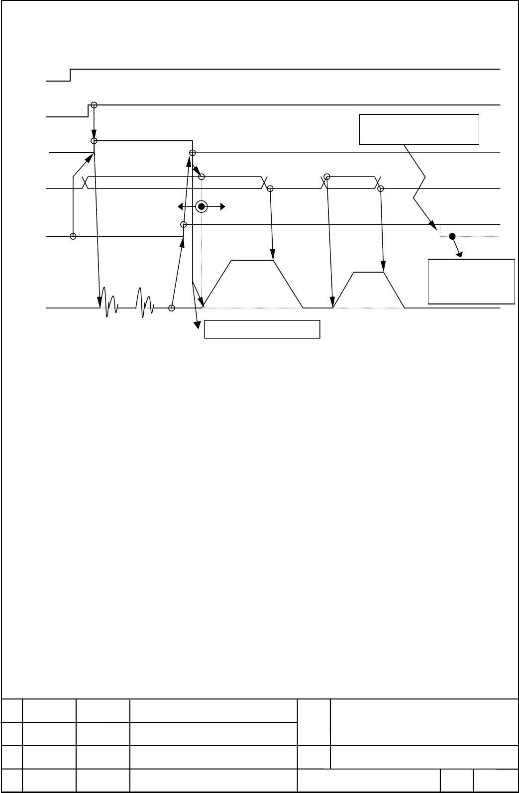
2.1.2. EPFSTR is the trigger signal case
2.1.2. EPFSTR is the trigger signal case2.1.2. EPFSTR is the trigger signal case
2.1.2. EPFSTR is the trigger signal case
Pole setting signal EPFIX and the start signal dedicated for pole detection EPFSTR is assumed to
correspond to the indicator or key respectively on the machine operator panel.
(1) Get the pole detection ready recognizing EPFIX=0 which means the indicator off.
(2) Set EPFSTR=1 to start the pole detection.
(3) The temporary pole setting is done after the motor moves at 0 and 90 degrees position and stop.
(4) The temporary pole setting turn EPFIX=1 with the indicator lit. Then turn EPFSTR=0.
(5) EPFSTR=0 run the motor with the velocity command former input. Afterward as usual.
(6) If an alarm happens which could lose the pole position already acquired, that makes EPFIX=0 of
the lost pole position. Try again the pole detection sequence from the first.
EPFSTR
Power
MRDY
& *ESP
& SFR/SRV
Velocity
command
EPFIX
Motor Velocit
y
0 position 90 position
movin
g
movin
g
Pole set
V
alid velocit
y
command
Lost pole position
Invalid velocit
y
command
P
o
l
e
d
e
t
ec
ti
o
n
co
m
p
l
e
t
e
A
larm lost pole position
ha
pp
ens
、
EPFIX=0
Lost pole pos.
Invalid velocity
command
Contents Summary of Spindle Motor (Synchronous Motor) Mounting sensor & Starting sequence Specifications Additional Manual
- Page 1Spindle Motor (Synchronous Motor) Mounting sensor & Starting sequence Specifications 1. Mounting sensor............................................................................................................................2 1.1 BZ sensor .........................................................
- Page 21. Mounting sensor The current of the synchronous motor is controlled according to the pole position of the magnet built in the motor rotor. There are two method prepared in the spindle control software in order to get the pole position. The first method uses a reference signal of BZ sensor as zero
- Page 3running out of the center moving of the ring within ±0.03mm for the detector. (7) Turn off DC supply and make certain the feedback signal correctly output. Refer to “FANUC BUILT-IN AC SPINDLE MOTOR α series specification description B-65202” as to the way of confirmation. (8) After moving the shaft
- Page 42. Starting sequence It is necessary that Spindle software recognizes the pole position of the synchronous motor to control the current. Spindle software uses BZ sensor with the synchronous motor to recognize the pole position. From now on, we abbreviate “the spindle software in Spindle module” to S
- Page 5rotation depends on initial position at the time. •Alarm 65 is issued when the rotation angle from 0 to 90 degrees position amount less than 80 degrees after confirming the stall at 90 degrees position. This might happen if the motor is locked up mechanically. If so, release it to move the motor aft
- Page 62.1.The sequence of Pole position detection The pole detection works only once after Power on or after happening of alarm that lose the pole position. The sequence of it is as (1) and (2) as described below. 2.1.1.SFR/SRV is trigger signal case Power MRDY & *ESP SFR or SRV Alarm lost pole position h
- Page 72.1.2. EPFSTR is the trigger signal case Power MRDY & *ESP Alarm lost pole position & SFR/SRV happens、EPFIX=0 EPFSTR Velocity command Lost pole position Pole set Invalid velocity command Valid velocity command EPFIX Lost pole pos. Invalid velocity command Motor Velocity 0 position 90 position Pole d
- Page 82.2.PMC signal for Pole position detection The below table summarizes the PMC signal necessary to achieve pole detection. The bold type is added this time for the synchronous motor. INPUT (PMC → CNC) FS15 FS16 #7 #6 #5 #4 #3 #2 #1 #0 G227 G070 MRDY SFR SRV G226 G071 *ESP G228 G073 EPFSTR SYMBOL MEAN