Spindle Motor (Synchronous Motor) Mounting sensor & Starting sequence Specifications Additional Manual Page 8
Additional Manual
Rev
DATE
CONTENTS
Takahashi
Design
TITLE
DNr. A-63639-067E
FANUC
PAGE
8/8
02
2000.11.09
PRM4008#6 added Toyozawa
Synchronous Spindle Motor
Mounting Sensor/Starting sequence
Specification
2.2.PMC signal for Pole position detection
2.2.PMC signal for Pole position detection2.2.PMC signal for Pole position detection
2.2.PMC signal for Pole position detection
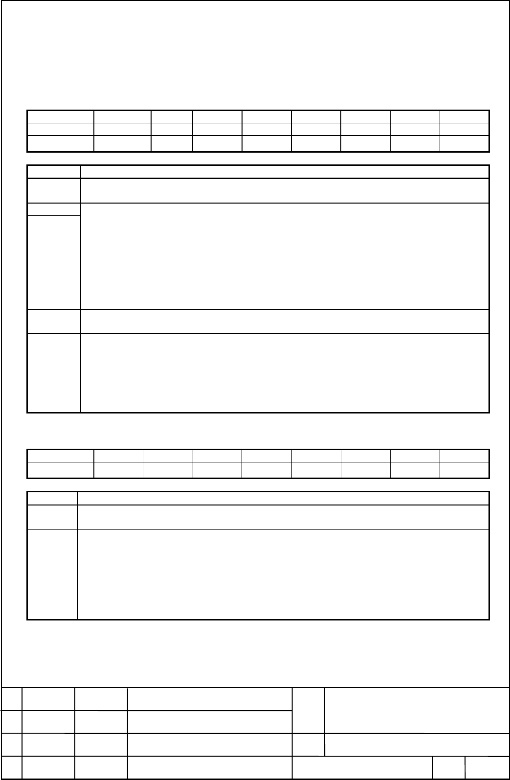
The below table summarizes the PMC signal necessary to achieve pole detection. The bold type is added
this time for the synchronous motor.
INPUT (PMC → CNC)
FS15 FS16 #7 #6 #5 #4 #3 #2 #1 #0
G227 G070 MRDY SFR SRV
G226 G071 *ESP
G228 G073
EPFST
R
SYMBOL MEANINGS & REMARKS
MRDY Machine Ready completed
Set to 1 before input the trigger of pole detection such as SFR/SRV or EPFSTR.
SFR
SRV
Forward Revolution command
Reverse Revolution command
These signal serve as both the rotation command and the trigger signal for pole
detection by inputting either SFR or SRV exclusive. Up to the temporary pole position
set, these signal have the meaning not of the direction but of the signal excites the
motor. In this case either SFR or SRV exclusive is to be turn on beforeEPFSTR=1.
As far as these signal are used to excite the motor, the velocity command is not
executed during EPFIX=0 (Lost pole position). But it becomes effective to drive the
motor as soon as EPFIX=1 (Pole position setting).
∗ESP
Emergency Stop
Set to one before the trigger signal for Pole detection.
EPFSTR
The trigger signal to start the pole detection.
This choice for the pole detection enable an operator to be conscious what he will do,
and to use together with EPFIX (Pole position state).
This signal must be turn off to zero after EPFIX set to one, because this signal make
the velocity command invalid and display Error-30 at SPM module. Besides, this signal
is not effective in case that SFR/SRV is chosen as the trigger signal for pole detection.
OUTPUT (PMC ← CNC)
FS15 FS16 #7 #6 #5 #4 #3 #2 #1 #0
F229 F045 ALM
F230 F048
EPFIX
SYMBOL MEANINGS & REMARKS
ALM Alarm status
SPM module falls in alarm state
EPFIX
Pole position status
0
00
0: means the pole position in lost state. The trigger signal starts the pole detection.
1
11
1: means on the pole position set by either temporary or fixed state. This signal reset
to zero if it is necessary to clear the pole position because of such an alarm as the
feedback disconnection. You can get an operator to be conscious the behavior of pole
detection if an indicator on machine panel is lit.
Contents Summary of Spindle Motor (Synchronous Motor) Mounting sensor & Starting sequence Specifications Additional Manual
- Page 1Spindle Motor (Synchronous Motor) Mounting sensor & Starting sequence Specifications 1. Mounting sensor............................................................................................................................2 1.1 BZ sensor .........................................................
- Page 21. Mounting sensor The current of the synchronous motor is controlled according to the pole position of the magnet built in the motor rotor. There are two method prepared in the spindle control software in order to get the pole position. The first method uses a reference signal of BZ sensor as zero
- Page 3running out of the center moving of the ring within ±0.03mm for the detector. (7) Turn off DC supply and make certain the feedback signal correctly output. Refer to “FANUC BUILT-IN AC SPINDLE MOTOR α series specification description B-65202” as to the way of confirmation. (8) After moving the shaft
- Page 42. Starting sequence It is necessary that Spindle software recognizes the pole position of the synchronous motor to control the current. Spindle software uses BZ sensor with the synchronous motor to recognize the pole position. From now on, we abbreviate “the spindle software in Spindle module” to S
- Page 5rotation depends on initial position at the time. •Alarm 65 is issued when the rotation angle from 0 to 90 degrees position amount less than 80 degrees after confirming the stall at 90 degrees position. This might happen if the motor is locked up mechanically. If so, release it to move the motor aft
- Page 62.1.The sequence of Pole position detection The pole detection works only once after Power on or after happening of alarm that lose the pole position. The sequence of it is as (1) and (2) as described below. 2.1.1.SFR/SRV is trigger signal case Power MRDY & *ESP SFR or SRV Alarm lost pole position h
- Page 72.1.2. EPFSTR is the trigger signal case Power MRDY & *ESP Alarm lost pole position & SFR/SRV happens、EPFIX=0 EPFSTR Velocity command Lost pole position Pole set Invalid velocity command Valid velocity command EPFIX Lost pole pos. Invalid velocity command Motor Velocity 0 position 90 position Pole d
- Page 82.2.PMC signal for Pole position detection The below table summarizes the PMC signal necessary to achieve pole detection. The bold type is added this time for the synchronous motor. INPUT (PMC → CNC) FS15 FS16 #7 #6 #5 #4 #3 #2 #1 #0 G227 G070 MRDY SFR SRV G226 G071 *ESP G228 G073 EPFSTR SYMBOL MEAN