Series 30i-MODEL A, Input of tool offset value measured B Additional Manual Page 8
Additional Manual
A-79344E
Title
Draw
No.
Ed. Date Design Description
Date Jan.06.’04 Design. Apprv.
6/24
page
FANUC Series 30i-MODEL A
Input of tool offset value measured B
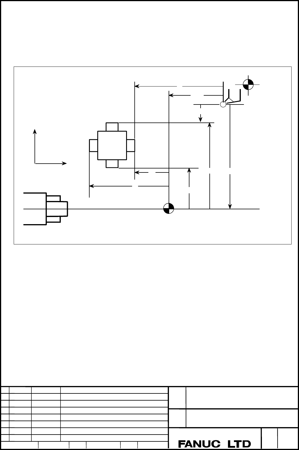
Example 2
The measuring reference point may be an imaginary point (imaginary zero point), as shown
in the figure below. The difference between the imaginary zero point and the measuring tool
nose tip position at the mechanical reference point can be set as the tool offset value of the
measuring tool, by setting the distances from the imaginary zero point to the respective
contact faces in parameters.
+X
Measuring tool nose
position at the mechani
cal reference position
(0,0)
Zt
Zm
Zp
Xp
Xm
OFSx
OFSZ
Xt
+Z
Machine zero
point
Measuring reference position
(Imaginary zero point)
When the imaginary zero position is set as the measuring reference position
・Setting the workpiece coordinate system shift amount
The workpiece coordinate system shift amount for the Z-axis can be set as follows: Bring the
tool to touch the workpiece end face. Subtract the tool geometry offset value of the tool (the
value shifted in the coordinate system by the tool geometry offset) from the machine
coordinate value (the distance from the measuring tool nose tip position at the mechanical
reference position (machine zero point) to the workpiece end face).The result is set as the
workpiece coordinate system shift value.
(Z axis workpiece coordinate system shift amount to be set
(EXOFSz) )
= (Z axis tool geometry offset value of the corresponding tool
(OFSz)) – (Z axis machine coordinate value(Zt))
Using the above methods, the workpiece coordinate system is set with the workpiece end face
(the contact point of the sensor) specified as the programmed zero point of the workpiece
coordinate system of the Z-axis.
Contents Summary of Series 30i-MODEL A, Input of tool offset value measured B Additional Manual
- Page 1TECHNICAL REPORT NO. TMN 04/020E Date :Mar .30, 2004 General Manager of Software Laboratory FANUC Series 30i-A Newly additional functions 1. Communicate this report to: Your information only GE Fanuc-N, GE Fanuc-E FANUC Robotics MILACRON Machine tool builder Sales agency End user 2. Summary for Sale
- Page 2FANUC Series30i –A newly additional functions Drawing number Functions 1 A-79227E External Data Input 2 A-79226E One Touch Macro call 3 A-79196E Temporary absolute coordinate setting 4 A-79354E System alarm 5 A-79349E Touch Panel Control 6 A-79253E Distance coded linear scale interface 7 A-79364E Li
- Page 3FANUC Series 30i-MODEL A Input of tool offset value measured B Specifications FANUC Series 30i-MODEL A Title Input of tool offset value measured B Draw A-79344E No. Ed. Date Design Description page 1/24 Date Jan.06.’04 Design. Apprv.
- Page 4General When the touch sensor is provided, the tool offset value can be automatically settable in the tool offset memory, by moving the tool to make contact with the touch sensor during manual operation. The workpiece coordinate system shift amount can also be automatically set. ・Touch sensor Either
- Page 5The tool offset value to be set differs according to the method of determining the measuring reference position. ・If touch sensor contact detection is based on a one-contact input If touch sensor contact detection is based on a one–contact input (the TS1 parameter (bit 3 of parameter No. 5004) is 1)
- Page 6Tool compensation Parameter(No.5053) number 8 10 Spindle 1 1~8 1~10 Spindle 2 9~32 11~32 Note If parameter No. 5053 for grouping tool compensation numbers is 0 or greater than the maximum allowable number of tool compensation sets, grouping is carried out as listed below. Number of tool 32 64 99 200
- Page 7Example 1 The difference between the reference tool nose tip position and the measuring tool nose tip position can be set as the tool offset value. Define the reference tool nose tip position at the mechanical reference position (machine zero position) as the measuring reference position, then set t
- Page 8Example 2 The measuring reference point may be an imaginary point (imaginary zero point), as shown in the figure below. The difference between the imaginary zero point and the measuring tool nose tip position at the mechanical reference point can be set as the tool offset value of the measuring tool
- Page 9・If the tool setter function for a one-turret/two-spindle lathe is used For the tool set function for a one–turret/two–spindle lathe, the workpiece coordinate shift amount for the Z–axis is automatically set in any of workpiece coordinate systems G54 to G59 for workpiece coordinate system memory. [Z
- Page 10Machine Zt zero point +X +Z OFSz -EXOFSz (0,0) Measuring tool no se position at the Workpiece coordinate OFSx mechanical machi system zero point ne position (programmed zero point) EXOFSz :Workpiece coordinate system shift amount to be set OFSz:Tool geometry offset value Zt:Mechanical coordinate val
- Page 11Basic procedure to set tool offset value To use the tool setter function for a one–turret/two–spindle lathe, first specify the spindle to be measured, using the S2TLS (G040.5) (spindle measurement select) signal. (1) Execute manual reference position return. By executing manual reference position re
- Page 12(9) Set the tool compensation value writing mode signal GOQSM to “0”. The writing mode is canceled and the blinking “OFST” indicator light goes off. When the tool setter function for a one–turret/two–spindle lathe is in use, the S1MES or S2MES (spindle under measurement) signal for the spindle being
- Page 13The writing mode is canceled and the blinking “WSFT” indicator light goes off. When the tool setter function for a one–turret/two–spindle lathe is in use, the S1MES or S2MES (spindle under measurement) signal, whichever is applicable, becomes 0. Signal Tool offset write mode select signal GOQSM<Gn03
- Page 14–MIT1 : Not used +MIT2 : Not used –MIT2 : Not used ・When signal GOQSM for selecting the mode for writing tool compensation is turned “1”, he manual feed interlock signal also automatically calculates the tool geometry compensation for the tool compensation number pointed to by the cursor and sets th
- Page 15Tool offset write signal +MIT1~ +MIT7<Gn132#0~ #7> -MIT1~-MIT7<Gn134#0~#7> [Classification] Input signal [Function] Each of these signals inhibits the tool from being fed along the orresponding axis during manual operation. When signal GOQSM for selecting the mode for writin g tool compensation is s
- Page 16Workpiece coordinate system shift value write mode select signal WOQSM<Gn039#6> [Classification] Input signal [Function] Selects the mode for writing the shift amount for the workpiece coordinate system. [Operation] When this signal is turned to “1” in a manual operation mode, the mode for writing t
- Page 17Signal address (Path 1) #7 #6 #5 #4 #3 #2 #1 #0 X004 -MIT2 +MIT2 -MIT1 +MIT1 SKIP5 SKIP4 SKIP3 SKIP2 (Path 2) #7 #6 #5 #4 #3 #2 #1 #0 #2 #2 #2 #2 X013 -MIT2 +MIT2 -MIT1 +MIT1 #2 #2 #2 #2 SKIP5 SKIP4 SKIP3 SKIP2 (Path 3) #7 #6 #5 #4 #3 #2 #1 #0 #3 #3 #3 #3 X011 -MIT2 +MIT2 -MIT1 +MIT1 #3 #3 #3 #3 SKI
- Page 18#7 #6 #5 #4 #3 #2 #1 #0 Gn039 GOQSM WOQSM OFN5 OFN4 OFN3 OFN2 OFN1 OFN0 #7 #6 #5 #4 #3 #2 #1 #0 Gn040 WOSET S2TLS OFN9 OFN8 OFN7 OFN6 #7 #6 #5 #4 #3 #2 #1 #0 Fn062 S2MES S1MES Parameter #7 #6 #5 #4 #3 #2 #1 #0 3003 DIT [Input type] Parameter input [Data type] Byte path #3 DIT Interlock for each axis
- Page 19Address to which the PMC axis control skip signal and measurement 3019 position arrival signals are assigned Note When this parameter is set, the power must be turned off before operation is continued. [Input type] Parameter input [Data type] Word path [Valid data range] 0 to 727 Set an X address to
- Page 20#7 #6 #5 #4 #3 #2 #1 #0 5004 TSI [Input type] Parameter input [Data type] Bit path #3 TSI When the tool offset measurement value direct input B function is used, touch sensor contact detection is based on. 0: Four-contact input 1: One-contact input #7 #6 #5 #4 #3 #2 #1 #0 5005 QNI [Input type] Param
- Page 21Number of pulse interpolation cycles memorized prior to contacting the 5021 touch sensor [Input type] Parameter input [Data type] Byte path [Valid data range] 0~8 This parameter sets the number of pulse interpolation cycles to be memorized until the operator manually touches the tool with a one–cont
- Page 225059 Distance (Z2M) between reference position and Z axis – contact surface (touch sensor 2 side) [Input type] Parameter input [Data type] Real path [Unit of data] mm, inch(input unit) [Minimum unit of data] Depend on the increment system of the applied axis [Valid data range] 0 or positive 9 digit
- Page 235020 Tool offset number used for the input of tool offset value measured B [Input type] Parameter input [Data type] Word path [Valid data range] 0 to the number of tools to be compensated. Set tool offset number used for the input of tool offset value measured B function (i.e. when workpiece coordin
- Page 245053 Bias for tool offset numbers for measured tool offset value setting [Input type] Parameter input [Data type] Word path [Valid data range] 1 to maximum tool offset count When the tool setter function for 1–turret, 2–spindle lathes is used, this parameter allocates tool offset numbers for measure
- Page 25Alarm and message Number Message Description DIRECTION CAN NOT For a one–contact input touch sensor 5195 BE JUDGED used with the tool compensation amoun t measurement value direct input B fun ction, stored pulse directions are not u nified. ・The machine is at a stop in the offset write mode. ・ The s
- Page 261.1 Notes This function is optional function. FANUC Series 30i-MODEL A Title Input of tool offset value measured B Draw A-79344E No. Ed. Date Design Description page 24/24 Date Jan.06.’04 Design. Apprv.