FANUC SERVO AMPLIFIER ßi series I/O Link option Additional Manual Page 63
Additional Manual
A
-77223E/02
図
番
名
称
ペ
|
ジ
変更内容 設計 年月日
版
FANUC SERVO AMPLIFIER βi series
I/O Link option
DESCRIPTIONS
63 /
Specifications of a recommended connector and case for cable K20 on
the βi series amplifier side
Connector : PCR-E20FS (Soldering type) (Honda Communications)
PCR-E20FA (Crimping type)
Case : PCR-V20L
Recommended cable for K20 cable
A66L-0001-0284#10P (10 twisted pair cable with a shield on the
outside)
NOTE
1 Maximum cable length: 10 m (when the above recommended
wire is used)
2 Use the same twisted wire pair for the SIN and *SIN signals.
Also use the same twisted wire pair for the SOUT and *SOUT
signals.
3 Do not make any connection to the pins other than those
shown above. Do not connect an unused conductor of the
cable.
4 Connect the shield of the cable to the ground plate of the
cabinet by using a cable clamp. Regardless of whether a β
series servo amplifier is connected with the host controller (or
the slave unit at the previous stage) or the slave unit at the
next stage, clamp and shield the cable immediately when the
cable is run into the cabinet. If the host controller is installed in
one cabinet, and a β series servo amplifier is installed in
another cabinet, shield processing is required twice for one
cable. Even if the cable is not routed outside the cabinet, be
sure to clamp and shield the cable at least one location.
5 Switch on the control power for the servo amplifier at the
same time with or before the host controller connected to the
servo amplifier through the I/O Link. When switching off the
host controller power, also switch off the servo amplifier
control power.
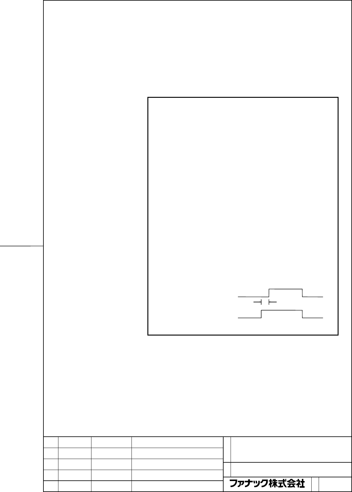
Host controller ON
Power OFF
Servo amplifier ON
control power OFF
t : 0 or more
t
Contents Summary of FANUC SERVO AMPLIFIER ßi series I/O Link option Additional Manual
- Page 1FANUC SERVO AMPLIFIER βi series I/O Link option DESCRIPTIONS FANUC SERVO AMPLIFIER βi series 名 I/O Link option 称 DESCRIPTIONS 図 A-77223E/02 01 04.03.22 Arimoto New drawing 番 ペ 版 年月日 設計 変更内容 | ジ 1 / 78
- Page 2TABLE OF CONTENTS 1 CONFIGURATION ................................................................................................. 4 1.1 SVM1-4i AND SVM1-20i ............................................................................... 5 1.2 SVM1-40i AND SVM1-80i .................................
- Page 35 TOTAL CONNECTION DIAGRAM ...................................................................... 32 5.1 CONNECTION DIAGRAM........................................................................... 33 5.1.1 SVM1-4i and SVM1-20i........................................................................
- Page 41 CONFIGURATION FANUC SERVO AMPLIFIER βi series 名 I/O Link option 称 DESCRIPTIONS 図 番 A-77223E/02 ペ 版 年月日 設計 変更内容 | ジ 4/
- Page 51.1 SVM1-4i AND SVM1-20i 4-A type, 20-A type βi SVM βi SVM 4A or 20A 4A or 20A FUSE FUSE Stabilized +24V etc Battery power supply 24V DC CXA19B CXA19A CXA19B CXA19A case I/O Link I/O Link CNC cable cable JD1B JD1A JD1B JD1A 200 to 240V AC Circuit Magnetic AC breaker contactor line CZ7 CZ7 filter Ext
- Page 61.2 SVM1-40i AND SVM1-80i 40-Atype, 80-A type βi βi SVM SVM 80A 40A FUSE FUSE Stabilized +24V etc Battery power supply CXA19B CXA19A CXA19B CXA19A case 24VDC I/O Link I/O Link CNC cable JD1B cable JD1A JD1B JD1A 3-phase 200V to 240VAC Magnetic AC Circuit breaker contactor line CZ4 CZ4 filter JA34 JA
- Page 72 SPECIFICATIONS FANUC SERVO AMPLIFIER βi series 名 I/O Link option 称 DESCRIPTIONS 図 番 A-77223E/02 ペ 版 年月日 設計 変更内容 | ジ 7/
- Page 82.1 SVM1-4i AND SVM1-20i Item Specification 3-phase 200 to 240 VAC Power supply voltage (drive) 1-phase 220 to 240 VAC Power supply voltage (control) 24VDC / 0.9A Dynamic brake Built-in FANUC SERVO AMPLIFIER βi series 名 I/O Link option 称 DESCRIPTIONS 図 番 A-77223E/02 ペ 版 年月日 設計 変更内容 | ジ 8/
- Page 92.2 SVM1-40i AND SVM1-80i Item Specification Power supply voltage (drive) 3-phase 200 to 240 VAC Power supply voltage (control) 24VDC / 0.9A Dynamic brake Built-in FANUC SERVO AMPLIFIER βi series 名 I/O Link option 称 DESCRIPTIONS 図 番 A-77223E/02 ペ 版 年月日 設計 変更内容 | ジ 9/
- Page 102.3 APPLICABLE MOTORS 0.2 0.3 0.4 0.5 1 2 4 8 12 22 α1 α2 α4 α8 α 12 α 22 αi /5000i /5000i /4000i /3000i /3000i /3000i (20A) (20A) (40A) (40A) (80A) (80A) α2 α4 α8 α 12 Motor α is /5000is /5000is /4000is /4000is (20A) (20A) (80A) (80A) β 0.2 β 0.3 β 0.4 β 0.5 β1 β2 β4 β8 β 12 β 22 β is /5000is /5000
- Page 112.4 COOLING FAN MOTORS 2.4.1 SVM1-4i AND SVM1-20i (INSTALL COOLING FAN MOTOR) The shipment of SVM1-4i and SVM1-20i in the condition that the body of SVM and the cooling fan motor were separated. The body of SVM and the cooling fan motor are able to grapple in the order of following (1), (2) and (3).
- Page 122.5 DERATING Consider derating as shown below, according to ambient temperatures. SVM1-20i Output derating for single-phase input 1200 Motor output(W) 900 0 0 35 55 Ambient temperature(℃) SVM1-80i Current derating 18.5 15.0 Motor current(A) 0 0 45 55 Ambient current(℃) FANUC SERVO AMPLIFIER βi serie
- Page 132.6 SEPARATED REGENERATIVE DISCHARGE RESISTOR 2.6.1 When No Separated Regenerative Discharge Resistor Is Needed Of SVM1-4 i and SVM1-20 i No separated regenerative discharge resistor is needed if the energy regenerated per regeneration cycle is not higher than the amount [J] of energy listed below.
- Page 14- For vertical movement (a) SI unit system −1 Q = 1.047 × 10 ⋅ Th ⋅ Vm ⋅ ta [ J ] (Expression2) Th: Upward torque that the motor applies at the time of downward rapid traverse [N・m] -1 Vm: Motor speed at rapid traverse [min ] ta : Rapid traverse acceleration/deceleration time [sec] (b) CGS unit syst
- Page 152.6.2 When a Separated Regenerative Discharge Resistor is Needed by SVM1-4 i and SVM1-20 i. If the amount of energy regenerated per regeneration cycle exceeds the maximum amount of energy that a servo amplifier can handle, a DC link over-voltage alarm occurs. In this case, a separated regenerative d
- Page 16- For vertical movement The amount of regenerative discharge (power [W]) when the operation duty for downward rapid traverse is D(%) (a) SI unit system −1 D w = 1.047 × 10 ⋅ Th ⋅ Vm × [W ] (Ecpression5) 100 Th: Upward torque that the motor applies at the time of downward rapid traverse [N・m] -1 Vm:
- Page 172.6.3 When Amplifier Models SVM-40i and SVM-80i Are Used If the amount of regenerative discharge from a servo motor exceeds the regenerative discharge capacity of the regenerative discharge resistor incorporated in the corresponding servo amplifier, a separated regenerative discharge resistor is nee
- Page 18Set-up switch (for changing the DC alarm level) Switch setting (for the SVM1-40i and SVM1-80i) The SVM1-40i and SVM1-80i each have four switches on their front panel for protecting regenerative resistors. Be sure to set these switches to the positions that match the resistors used. CAUTION An incorr
- Page 19Cautions for selecting a regenerative discharge resistor CAUTION 1 Regenerative discharge resistors may become very hot (100 to 200 °C). Be careful not to touch them. 2 Before touching a regenerative discharge resistor, for example, for maintenance purposes, turn off all power to the amplifier, wait
- Page 203 ORDERING INFORMATION Refer to the order list (B-65321EN). FANUC SERVO AMPLIFIER βi series 名 I/O Link option 称 DESCRIPTIONS 図 番 A-77223E/02 ペ 版 年月日 設計 変更内容 | ジ 20 /
- Page 214 EXTERNAL DIMENSIONS CUT-OUT DRAWINGS / MAINTENANCE / PANEL AREA FANUC SERVO AMPLIFIER βi series 名 I/O Link option 称 DESCRIPTIONS 図 番 A-77223E/02 ペ 版 年月日 設計 変更内容 | ジ 21 /
- Page 224.1 EXTERNAL DIMENSIONS 4.1.1 External Dimensions of SVM1-4i and SVM1-20i Weight: 1.3kg FANUC SERVO AMPLIFIER βi series 名 I/O Link option 称 DESCRIPTIONS 図 番 A-77223E/02 ペ 版 年月日 設計 変更内容 | ジ 22 /
- Page 234.1.2 External Dimensions of SVM1-40i and SVM1-80i Weight: 4.2kg FANUC SERVO AMPLIFIER βi series 名 I/O Link option 称 DESCRIPTIONS 図 番 A-77223E/02 ペ 版 年月日 設計 変更内容 | ジ 23 /
- Page 244.1.3 External Dimensions of Fan Unit (A06B-6134-K002) External dimensions of fan unit (A06B-6134-K002) FANUC SERVO AMPLIFIER βi series 名 I/O Link option 称 DESCRIPTIONS 図 番 A-77223E/02 ペ 版 年月日 設計 変更内容 | ジ 24 /
- Page 254.1.4 External Dimensions of Regenerative Resistor (A06B-6130-H401) FANUC SERVO AMPLIFIER βi series 名 I/O Link option 称 DESCRIPTIONS 図 番 A-77223E/02 ペ 版 年月日 設計 変更内容 | ジ 25 /
- Page 264.1.5 External Dimensions of Regenerative Resistor (A06B-6130-H402) FANUC SERVO AMPLIFIER βi series 名 I/O Link option 称 DESCRIPTIONS 図 番 A-77223E/02 ペ 版 年月日 設計 変更内容 | ジ 26 /
- Page 274.2 PANEL CUT-OUT DRAWINGS 4.2.1 SVM1-4i and SVM1-20i FANUC SERVO AMPLIFIER βi series 名 I/O Link option 称 DESCRIPTIONS 図 番 A-77223E/02 ペ 版 年月日 設計 変更内容 | ジ 27 /
- Page 284.2.2 SVM1-40i and SVM1-80i NOTE Attach the accompanying gasket around the panel cut-out to prevent oil and dust from getting into it. Reinforce the right and left sides of the panel cut-out in the power magnetics cabinet by using fittings such as L-angles to maintain satisfactory contact between th
- Page 294.3 MAINTENANCE AREA 4.3.1 Maintenance Area for the SVM1-4i and SVM1-20i FANUC SERVO AMPLIFIER βi series 名 I/O Link option 称 DESCRIPTIONS 図 番 A-77223E/02 ペ 版 年月日 設計 変更内容 | ジ 29 /
- Page 304.3.2 Maintenance Area for the SVM1-40i and SVM1-80i When no cooling fan AC motor (A06B-6134-K002) is used to cool the heat sink FANUC SERVO AMPLIFIER βi series 名 I/O Link option 称 DESCRIPTIONS 図 番 A-77223E/02 ペ 版 年月日 設計 変更内容 | ジ 30 /
- Page 31When the cooling fan AC motor (A06B-6134-K002) is used to cool the heat sink FANUC SERVO AMPLIFIER βi series 名 I/O Link option 称 DESCRIPTIONS 図 番 A-77223E/02 ペ 版 年月日 設計 変更内容 | ジ 31 /
- Page 325 TOTAL CONNECTION DIAGRAM FANUC SERVO AMPLIFIER βi series 名 I/O Link option 称 DESCRIPTIONS 図 番 A-77223E/02 ペ 版 年月日 設計 変更内容 | ジ 32 /
- Page 335.1 CONNECTION DIAGRAM 5.1.1 SVM1-4i and SVM1-20i 4-A type, 20-A type βi SVM βi SVM 4A or 20A 4A or 20A FUSE FUSE Stabilized K6 K6 Battery K9 power supply CXA19B CXA19A CXA19B CXA19A case 24VDC CNC K20 K20 JD1B JD1A JD1B JD1A 3-phase 200 to 240VAC AC K2 K2 Circuit Magnetic line CZ7 CZ7 contactor fil
- Page 34NOTE 1 Always install the circuit breakers, magnetic contactor, and AC line filter. 2 To protect the equipment from lightning surge voltages, install a lightning surge absorber across each pair of power lines and across each power line and the grounding line at the power inlet of the power magnetics
- Page 355.1.2 SVM1-40i and SVM1-80i 40-A type, 80-A type βi βi SVM SVM 80A 40A FUSE FUSE Stabilized K6 Battery CXA19B CXA19A K6 CXA19B CXA19A K9 case power supply 24VDC CNC K20 K20 JD1B JD1A JD1B JD1A 3-phase 200 to 240VAC Circuit Magnetic AC breaker contactor line CZ4 CZ4 filter K2 K2 K7 K22 External 5A CX
- Page 36NOTE 1 Always install the circuit breakers, magnetic contactor, and AC line filter. 2 To protect the equipment from lightning surge voltages, install a lightning surge absorber across each pair of power lines and across each power line and the grounding line at the power inlet of the power magnetics
- Page 375.2 CONNECTOR LOCATION 5.2.1 SVM1-4i and SVM1-20i No. Name Remarks 1 DC link charge LED 2 CZ7-1 Main power input connector (1) 3 CZ7-2 Discharge resistor connector 4 CZ7-3 Motor power connector Connector for main power MCC control (8) 5 CX29 signal (9) 6 CX30 ESP signal connection connector Regenera
- Page 385.2.2 SVM1-40i and SVM1-80i No. Name Remarks 1 DC link charge LED Connector for main power 2 CX29 MCC control signal 3 CX30 ESP signal connection connector Regenerative resistor connector 4 CXA20 (for alarms) Setting switch 5 SW (DC alarm level) 6 CZ4 Main power input connector (9) 7 CZ5 Motor power
- Page 395.2.3 Details of Cable K1 5.2.3.1 Servo motor αi , αis series, Servo motor βis series(β0.4/5000is to β22/2000is) Shield SVM Servo motor (1) SD (2) (2) *SD (1) (5) REQ (6) (6) *REQ (5) (9, 20) 5V (8, 9) (12, 14) 0V (7, 10) (7) 6V (4) Drain (16) wire FG (3) 20-pin half-pitch connector Connector (Japan
- Page 40NOTE 1 In case that the cable is prepared by MTB, total resistance of 5V and 0V must be less than 2Ω. 2 Pulsecoder side connector can accept maximum 0.5mm2 (wire construction 20/0.18 or 104/0.08, insulation outer diameter φ1.5 or less) wire and sheath diameter is φ5.7 to φ8.0. In case of using thick
- Page 415.2.3.2 Servo motor βis series(β0.2/5000is, β0.3/5000is) Shield SVM Servo motor (1) SD (A 4) (2) *SD (B 4) (5) REQ (A3) (6) *REQ (B3) (9, 20) 5V (A2, B2) (12, 14) 0V (A1, B1) (7) 6V (A5) (16) Drain wire FG (B6) 20-pin half-pitch connector Housing : 1-1318118-6 (D-2100D 12 poles) Contact : 1318107-1
- Page 42NOTE 1 The ground plate to which the shield is connected must be placed as close as possible to the servo amplifier so that distance between the ground plate and the servo amplifier becomes shortest. 2 In case that the cable is prepared by the user, the total resistance (round trip) of 5 V and 0 V m
- Page 435.2.4 Details of Cable K2 The following items related to servo amplifier input cables are explained below in the stated order. (1) Details of connectors (2) Selecting input cables (general) (3) Details of input cables FANUC SERVO AMPLIFIER βi series 名 I/O Link option 称 DESCRIPTIONS 図 番 A-77223E/02 ペ
- Page 445.2.4.1 Details of connectors (a) SVM1-4, SVM1-20 Βi Servo amplifier CZ7 (B1) L1 CZ7 (A1) L2 CZ7 (B2) L3 CZ7 (A2) [Receptacle housing] Use the following receptacle housing. Manufacturer- Specification of the key Manufacture defined model 175363-3 Incorrect-insertion prevent key Tyco Electronics AMP
- Page 45(b) SVM1-40, SVM1-80 Βi Servo amplifier CZ4 (B1) L1 CZ4 (A1) L2 CZ4 (B2) L3 CZ4 (A2) [Receptacle housing] Use the following receptacle housing. Manufacturer-defined Specification of Manufacture model the key 1-917807-2 XX Tyco Electronics AMP [Receptacle contact] Conductor Conductor Rectangle contac
- Page 465.2.4.2 Selecting cables (general) Select the cable specification by considering the following conditions for use: (1) Motor current rating or current needed in use on a real machine (2) Cable type (heat resistance temperature, etc.) (3) Environment in which the cable is installed (operating ambient
- Page 475.2.4.3 Details of input cables Select cables by taking the following conditions for use into account. [Example combinations of input cables for servo motors running with continuous-rating output (reference only)] Continuous Continuous [Example 1.] [Example 2.] current rating for current rating for
- Page 485.2.5 Details of Cable K3 The following items related to servo motor/amplifier power cables are explained below in the stated order. (1) Details of connectors (2) Selecting power cables (general) (3) Power cable for servo motor FANUC SERVO AMPLIFIER βi series 名 I/O Link option 称 DESCRIPTIONS 図 番 A-7
- Page 495.2.5.1 Details of connectors The D-3000 and -5000 connector series (manufactured by Tyco Electronics AMP.) are used for power cable connection in the βi series. The specifications of a receptacle housing and contact vary depending on the model for which they are used as stated below. (a) SVM1-4i, S
- Page 50(b) SVM1-40i, SVM1-80i βi Servo amplifier Motor CZ5 (B1) U U CZ5 (A1) V V CZ5 (B2) W W CZ5 (A2) GND (Body) [Receptacle housing] Use the following receptacle housing. Manufacturer-defined Specification of the Manufacture model key 2-917807-2 YY Tyco Electronics AMP [Receptacle contact] Conductor Cond
- Page 515.2.5.2 Details of cables (general) See Subsection 5.2.4 “Details of Cable K2.” FANUC SERVO AMPLIFIER βi series 名 I/O Link option 称 DESCRIPTIONS 図 番 A-77223E/02 ペ 版 年月日 設計 変更内容 | ジ 51 /
- Page 525.2.5.3 Power cable for servo motor A servo motor power cable assembly consists of: (a) Power cable (b) Motor-side connector (a) Power cable Examples of combining a servo motor and power cable are described below according to Subsection 5.2.4.2, “Selecting cables (general).” [Example combination of
- Page 535.2.6 Details of Cables K4 and K5 5.2.6.1 SVM1-4i and SVM1-20i When a regenerative discharge resistor is used The following regenerative discharge resistor models are available. The following housing and contact are A06B-6130-H401 connected to the resistor. The following housing and contact are A06B
- Page 54When no regenerative discharge resistor is used βi SVM CZ7(DCP) B1 Keep these pins unconnected. (Do not install a jumper between the pins.) CZ7(DCC) A1 Install a jumper between the pins. CXA20-1 (TH1) CXA20-2 (TH2) Housing : 1-1318120-3 Contact : 1318107-1 Manufacture : Tyco Electronics AMP Wire cro
- Page 555.2.6.2 SVM1-40i and SVM1-80i When a separated regenerative discharge resistor is used βi SVM Separated regenerative discharge resistor CZ6-B1 (RC) CZ6-B2 (RE) Cable specification: Two-conductor polyvinyl heavy-duty power cable (JIS C3312), Conductor size of 3.5 mm2, Crimp terminal: 5.5-4 Housing :
- Page 56When a built-in regenerative discharge resistor is used βi SVM CZ6-A1 (RC) Install a jumper between the pins. CZ6-A2 (RI) Cable specification: Two-conductor polyvinyl heavy-duty power cable (JIS C3312), Conductor size of 3.5 mm2, Crimp terminal: 5.5-4 Housing : 3-917807-2 Contact : 316041-6 Applicab
- Page 575.2.7 Details of Cable K6 βi SVM βi SVM CXA19B-A1 (24V) CXA19A –A1 (24V) CXA19B-B1 (24V) CXA19A-B1 (24V) CXA19B-A2 (0V) CXA19A –A2 (0V) CXA19B-B2 (0V) CXA19A-B2 (0V) CXA19B-A3 (ESP) CXA19A –A3 (ESP) CXA19B-B3 (BAT) CXA19A-B3 (BAT) Housing : 1-1318119-3 Housing : 1-1318119-3 Contact : 1318107-1 Conta
- Page 585.2.8 Details of Cable K7 MCC βiSVM CX29-1 Spark (RLY1) Internal Coil killer contact CX29-3 (RLY2) External power supply (must mach the coil voltage of the users equipment) Housing : 3-1318130-3 Contact : 1318107-1 Applicable wire: 0.3 to 0.85 mm2 Manufacture : Tyco Electronics AMP Internal-contact
- Page 595.2.9 Details of Cable K8 βi SVM CX30-1 (24V) CX30-3 (ESP) Housing : 2-1318120-3 Contact : 1318107-1 Applicable wire: 0.3 to 0.85mm2 Manufacture : Tyco Electronics AMP FANUC SERVO AMPLIFIER βi series 名 I/O Link option 称 DESCRIPTIONS 図 番 A-77223E/02 ペ 版 年月日 設計 変更内容 | ジ 59 /
- Page 605.2.10 Details of Cable K9 βi SVM Battery case CXA19B-A1 (24V) CXA19B-B1 (24V) CXA19B-A2 (0V) 0V CXA19B-B2 (0V) CXA19B-A3 (ESP) CXA19B-B3 (BAT) 6V Housing : 1-1318119-3 Crimp terminal : 1.25-2 Contact : 1318107-1 Applicable wire : 0.3 to 0.85mm2 Applicable wire : 0.3 to 0.85mm2 Manufacture : Tyco El
- Page 615.2.11 Details of Cable K20 (Connection of FANUC I/O LINK) 5.2.11.1 Overview The FANUC I/O Link is a serial interface for connecting a CNC, SVM, I/O Unit-A, Power Mate, and so forth to transfer I/O signals (bit data) at high-speed among those units. When multiple units are connected by using the FAN
- Page 625.2.11.2 FANUC I/O Link CONNECTION VIA ELECTRIC CABLE Details of connection of cable K20 (when a connection is made with the host controller or the slave unit at the previous stage) Host controller or slave unit at β series amplifier the previous stage JD1A1/JD1A JD1B SIN (1) (3) SOUT *SIN (2) (4) *
- Page 63Specifications of a recommended connector and case for cable K20 on the βi series amplifier side Connector : PCR-E20FS (Soldering type) (Honda Communications) PCR-E20FA (Crimping type) Case : PCR-V20L Recommended cable for K20 cable A66L-0001-0284#10P (10 twisted pair cable with a shield on the outs
- Page 645.2.11.3 FANUC I/O Link CONNECTION VIA OPTICAL CABLE By using an optical cable with an optical I/O Link adapter, the FANUC I/O Link can be extended up to 200 m. For details, refer to the manual of the host controller FANUC SERVO AMPLIFIER βi series 名 I/O Link option 称 DESCRIPTIONS 図 番 A-77223E/02 ペ
- Page 655.2.12 Details of Cable K20 (Connection of Built-in DI) 5.2.12.1 Input signal specification The DC input signals are those sent from the machine to the servo unit. They are transferred via a non-insulated interface that can be switched between sink type (24V common) and source type (0V common) excep
- Page 665.2.12.2 List of signals (1)*+OT : Setting the positive overtravel signal input (*+OT) to logical 0 disables forward movement. This signal can be made unusable by parameter setting. (2)*-OT : Setting the negative overtravel signal input (*-OT) to logical 0 disables reverse movement. This signal can
- Page 675.2.12.3 Signal connection with the Power Magnetics Cabinet SVM JA72 +24V +24V (10),(19) Interlock signal input (Deceleration signal input for reference position return) *RILK (6) Filter and receiver Positive overtravel signal input *+OT (7) Filter and receiver Negative overtravel signal input *+OT
- Page 685.2.12.4 Skip signal interface SVM JA72 HDI (15) Receiver 0V (12,14,16) High-Speed Skip Signal Input Specification Circuit configuration SVM Shield Driver Filter Receiver IiH / IiL VH / VL Absolute maximum rating Input voltage range Vin: -3.6V to +13.6V Input characteristics Item Symbol Rating Unit
- Page 695.2.13 Details of Cable K22 (External Pulse input) SVM enables operation according to externally applied pulses. As an external pulse generator, an A/B-phase pulse generator of differential type satisfying the specification or a manual pulse generator available from FANUC can be selected. When a man
- Page 705.2.13.1 Connection when an A/B-Phase pulse generator of differential type is used K22 Cable Connection K22 External Pulse SVM Generator JA34 PA (1) PA *PA (2) *PA PB (3) PB *PB (4) *PB +5V (9) +5V +5V (18) +5V +5V (20) +5V 0V (12) 0V 0V (14) 0V 0V (16) 0V Connector : FI40-2015S (Hirose Electric) Ca
- Page 715.2.13.2 Connection when a manual pulse generator available from FANUC is used K23 Cable Connection The K23 cable is a signal cable for connecting a manual pulse generator with a manual pulse generator adapter (JA54). Manual pulse generator adapter JA54 Manual pulse generator Connector : FI40-2015S
- Page 72To one manual pulse generator, multiple (up to six) units of the SVM can be connected. In this case, prepare one manual pulse generator adapter for each unit of the SVM. A unit of the SVM can be connected with a manual pulse generator adapter in the same way as described in Subsection 5.2 "K24 Cable
- Page 73K24 Cable Connection The K24 cable is a signal cable for connecting a manual pulse generator adapter (JA55) with the SVM (JA34). Manual pulse generator SVM JA55 JA34 (PCR-EV20MDT) (PCR-EV20MDT) 1 PA 11 1 PA 11 2 *PA 12 0V 2 *PA 12 0V 3 *PB 13 3 PB 13 4 *PB 14 0V 4 *PB 14 0V 5 15 K24 5 15 6 16 0V 6 1
- Page 74Manual Pulse Generator Adapter External view Weight : Approx. 100g Installation condition The manual pulse generator adapter does not have a closed structure. So, install a manual pulse generator adapter in a closed cabinet similar to a one used for the SVM. The manual pulse generator adapter has tw
- Page 75- Operating condition The maximum allowable frequency of an input signal is 100 kHz. 1) Plus-direction move command pulses PA *PA PB *PB Tp Tp Tp Tp Tcyc 2) Minus-direction move command pulses PA *PA PB *PB Tp Tp Tp Tp Tp : 1.2 µsec or more Tcyc Tcyc : 10 µsec or more 3) Sequence External input PA p
- Page 76Example of recommended circuit SVM External pulse generator SN75113 or equivalent Receiver circuit 5 4,3 PA PA 6 7 *PA 9 1,2 10 11 12,13 PB *PB 14,15 The numbers indicate the pin numbers of SN75113. 12,14,16 FANUC SERVO AMPLIFIER βi series 名 I/O Link option 称 DESCRIPTIONS 図 番 A-77223E/02 ペ 版 年月日 設計
- Page 776 HEAT DISSIPATION The amount of heat dissipation depends on the SVM model and the current that flows through the servo motor. For the current that flows through a servo motor, reference the continuous rated current of each servo motor. (For the continuous rated current of each servo motor, refer to
- Page 78(2) Residual amount of heat in the cabinet By placing the heat sink section outside the cabinet, the residual amount of heat in the cabinet can be calculated according to the expression below. Residual amount of heat in the cabinet = a + Kb1 × b1 a: Amount of heat dissipation determined by the SVM m