DeviceNet Board for FANUC Series 30i/300i, 31i/310i, 32i/320i-MODEL A Operators manual Page 77
Operators manual
B-64044EN/01 MAINTENANCE 1.HARDWARE
- 69 -
1.2 LED INDICATORS AND THEIR MEANINGS
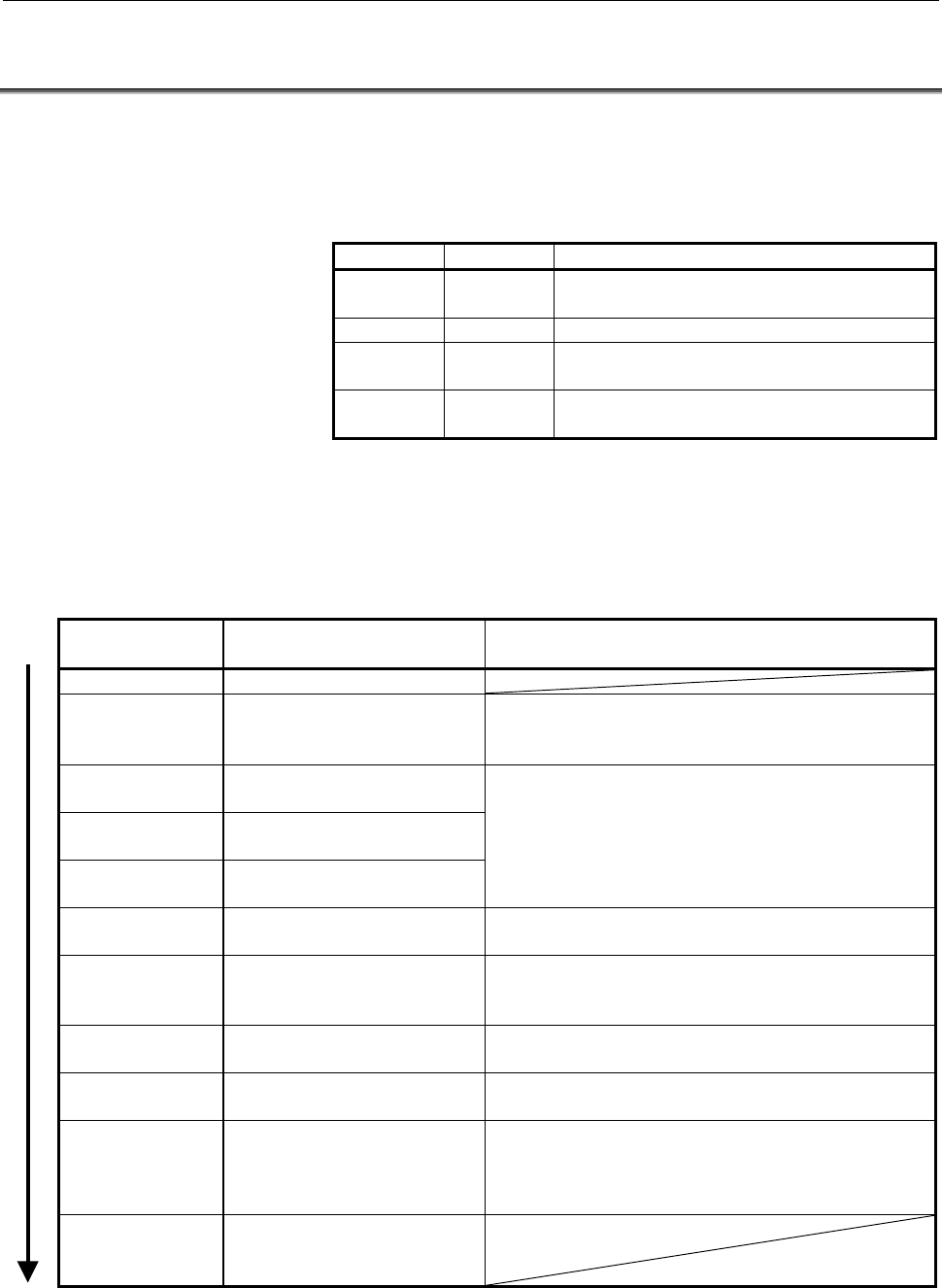
This board provides four green LEDs (STATUS) and one red LED
(ALARM) for status indication.
In addition, the internal daughter board has two LEDs that emit red
and green light.
Name Color Description
LED0 to 3 Green Indicates the activation state of the DeviceNet
software.
LEDWD Red Indicates an error on the daughter board.
MS Red/Green MS (Module Status) indicates the states of
nodes.
NS Red/Green NS (Network Status) indicates the state of the
network.
In the following explanations, the LED lighting states are expressed as
follows:
: Off : On : Blinking ◊: Don't care
LED display transition for LED0, LED1, LED2, and LED3 (during power-on)
LED indication
L3L2L1L0
State and cause when
stopped after power-on
Action when stopped after power-on
Power-off
After power-on, the DeviceNet
application software does not
start.
Store the DeviceNet application software in the flash
ROM of the CNC.
Initializing the firmware on the
daughter board.
Checking memory on the
daughter board.
Recognizing the firmware on
the daughter board.
Replace the DeviceNet master board.
Reading DeviceNet
parameters.
Enable the DeviceNet master function (software
option).
Verifying that DeviceNet
parameter "network" is set to
"online."
Set DeviceNet parameter "network" to "online."
Setting the bus parameter in
DeviceNet parameters.
Replace the DeviceNet master board.
Setting the slave parameter in
DeviceNet parameters.
Set the slave parameter in DeviceNet parameters
correctly. Or, replace the DeviceNet master board.
Checking duplicate MAC IDs. Check duplication with the MAC ID of a slave device.
Check if cables are connected correctly.
Check if power for communication is correctly supplied.
Check if slave devices are turned on.
The DeviceNet application
software has been initialized
and I/O communication starts.
Contents Summary of DeviceNet Board for FANUC Series 30i/300i, 31i/310i, 32i/320i-MODEL A Operators manual
- Page 1FANUC DeviceNet Board For FANUC Series 30*/300*, 31*/310*, 32*/320*-MODEL A OPERATOR’S MANUAL B-64044EN/01
- Page 2• No part of this manual may be reproduced in any form. • All specifications and designs are subject to change without notice. The export of this product is subject to the authorization of the government of the country from where the product is exported. In this manual we have tried as much as possi
- Page 3B-64044EN/01 SAFETY PRECAUTIONS SAFETY PRECAUTIONS “SAFETY PRECAUTIONS” describes the safety precautions related to the use of CNC units, to ensure safe operation of machines fitted with FANUC CNC units. Read this section carefully before attempting to use any function described in this manual. User
- Page 4SAFETY PRECAUTIONS B-64044EN/01 1.1 DEFINITION OF WARNING, CAUTION, AND NOTE This manual includes safety precautions for protecting the user and preventing damage to the machine. Precautions are classified into Warning and Caution according to their bearing on safety. Also, supplementary information
- Page 5B-64044EN/01 SAFETY PRECAUTIONS 1.2 GENERAL WARNINGS AND NOTES WARNING 1 Before operating the machine, thoroughly check the entered data. Operating the machine with incorrect data may result in the machine behaving unexpectedly, possibly causing damage to the workpiece and/or machine itself, or inju
- Page 6SAFETY PRECAUTIONS B-64044EN/01 CAUTION 1 Immediately after switching on the power, do not touch any of the keys on the MDI panel until the position display or alarm screen appears on the CNC unit. Some of the keys on the MDI panel are dedicated to maintenance or other special operations. Pressing a
- Page 7B-64044EN/01 TABLE OF CONTENTS TABLE OF CONTENTS SAFETY PRECAUTIONS............................................................................s-1 I. GENERAL 1 GENERAL ............................................................................................... 3 1.1 ORGANIZATION .................
- Page 8TABLE OF CONTENTS B-64044EN/01 2.3 MOUNTING ................................................................................................. 64 2.3.1 Mounting into the LCD-mounted Type Unit .........................................................64 2.3.2 Mounting into the Stand-alone Type Unit....
- Page 9I. GENERA
- Page 10
- Page 11B-64044EN/01 GENERAL 1.GENERAL 1 GENERAL This manual describes the DeviceNet functions of the FANUC Series 30i/300i, 31i/310i, 32i/320i -A. This chapter explains the organization of this manual and applied models. Trademark DeviceNet is a trademark of ODVA (Open DeviceNet Vendor Association). -3-
- Page 121.GENERAL GENERAL B-64044EN/01 1.1 ORGANIZATION This manual consists of the following parts: SAFETY PRECAUTIONS Describes the precautions which must be observed when any of the functions explained in this manual is used. I. GENERAL Describes the organization of this manual, and lists applicable mode
- Page 13B-64044EN/01 GENERAL 1.GENERAL 1.2 APPLICABLE MODELS The models covered by this manual are as follows. The abbreviations listed below may be used to refer to the corresponding models. Model name Abbreviation FANUC Series 30i-MODEL A Series 30i -A 30i –A 30i -A FANUC Series 300i-MODEL A Series 300i -
- Page 142.OVERVIEW OF DeviceNet FUNCTIONSGENERAL B-64044EN/01 2 OVERVIEW OF DeviceNet FUNCTIONS DeviceNet a field network to which CNCs, PLCs, sensors, or other control units can be connected. FANUC Series 30i-A (Master #0) DeviceNet PLC from Sensor from FANUC Series FANUC other other 16i-A Power Mate i-D c
- Page 15B-64044EN/01 GENERAL 2.OVERVIEW OF DeviceNet FUNCTIONS Specifications of the master functions Setting range of the MAC ID of the master 0 to 63 Setting range of the MAC IDs of slaves for 0 to 63 (excluding the MAC ID which communication can be made of the master) Master Maximum number of slaves for
- Page 16
- Page 17II. SETTIN
- Page 18
- Page 19B-64044EN/01 SETTING 1.DeviceNet FUNCTIONS 1 DeviceNet FUNCTIONS This part describes how to set the master functions of DeviceNet CAUTION After setting DI/DO data, make sure communication is performed correctly in a state in which security is retained. Operating the system without confirmation may c
- Page 201.DeviceNet FUNCTIONS SETTING B-64044EN/01 1.1 MASTER FUNCTION SETTING The setting screen of the DeviceNet master function consists of the BUS PARAMETRE screen and SLAVE PARAMETER screen. To perform DeviceNet communication, set the bus parameter and slave parameter. The bus parameter is required to
- Page 21B-64044EN/01 SETTING 1.DeviceNet FUNCTIONS BUS PARAMETER screen Procedure 1 Press soft key [BUS PARAM] to display the BUS PARAMETER screen (Screen 1-1). PAGE 2 On the BUS PARAMETER screen, page keys PAGE can be used to switch between pages. 3 Move the cursor to the item to set and then enter the par
- Page 221.DeviceNet FUNCTIONS SETTING B-64044EN/01 Setting item Item Description NETWORK Sets whether the DeviceNet master is removed from or added to the network. OFFLINE : Removed from the network. ONLINE : Added to the network. BAUDRATE Sets the communication rate. The communication rate is limited by th
- Page 23B-64044EN/01 SETTING 1.DeviceNet FUNCTIONS COMMON STATUS This is status information found by the DeviceNet master. The common status includes four types of status information: DeviceNet MPU status 1, DeviceNet MPU status 2, master function status 1, and slave communication states 1 to 8. The common
- Page 241.DeviceNet FUNCTIONS SETTING B-64044EN/01 Bit 8 : Failed to read the error record. Bit 9 to Bit 14 : Reserved. Bit 15 : An error record has been registered. Master function status 1 Bit 0 : A verification error has occurred. (The DI/DO size set in the bus parameter differs from that of the actual s
- Page 25B-64044EN/01 SETTING 1.DeviceNet FUNCTIONS CAUTION Keep the following in mind when setting the address and size of the common status. <1> The R address or E address can be set. For multipath PMC, the PMC address has the following format.
: For example, for the second path o - Page 261.DeviceNet FUNCTIONS SETTING B-64044EN/01 Communication cycle time This time is measured from when I/O data communication to the slave with a certain node number is processed until I/O data communication to the slave with the node number is processed again. The communication cycle time depends on w
- Page 27B-64044EN/01 SETTING 1.DeviceNet FUNCTIONS SLAVE PARAMETER screen Procedure 1 Press soft key [SLAVE TABLE] to display the SLAVE TABLE screen (Screen 1-2). The SLAVE PARAMETER screen includes 64 pages for all nodes. 2 To switch between pages on the SLAVE PARAMETER screen, PAGE use page keys PAGE , so
- Page 281.DeviceNet FUNCTIONS SETTING B-64044EN/01 Setting item Item Description COMMUNICATE Sets whether communication with the slave of this node number is enabled or disabled. DISABLE: Communication is disabled. ENABLE: Communication is enabled. DETAIL STATUS Sets the address of the PMC area in which the
- Page 29B-64044EN/01 SETTING 1.DeviceNet FUNCTIONS DETAIL STATUS ADDRESS Status information of each slave detected by the DeviceNet master. The detailed status occupies a 1-byte area beginning at the detail status address. DETAIL STATUS DETAIL STATUS ADDRESS Slave communication status details (1 byte) Slave
- Page 301.DeviceNet FUNCTIONS SETTING B-64044EN/01 DI DATA This is input data of the DeviceNet master function. Data transferred from a slave is stored in the PMC area as input data (DI data). CAUTION Keep the following in mind when setting the address and size of the DI data. <1> The R address or E address
- Page 31B-64044EN/01 SETTING 1.DeviceNet FUNCTIONS DO DATA This is output data of the DeviceNet master function. The data stored in the PMC area is transferred to a slave as output data (DO data). CAUTION Keep the following in mind when setting the address and size of the DO data. <1> The R address or E add
- Page 321.DeviceNet FUNCTIONS SETTING B-64044EN/01 1.2 MAINTENANCE SCREEN OF THE DeviceNet MASTER FUNCTION The MAINTENANCE screen of the DeviceNet master function consists of the NODE INFORMATION screen and MONITOR screen. The NODE INFORMATION screen is required to check the status of the whole DeviceNet ne
- Page 33B-64044EN/01 SETTING 1.DeviceNet FUNCTIONS NODE INFORMATION screen Procedure 1 Press soft key [NODE INFORM] to display the NODE INFORMATION screen (Screen 1-3). 2 When you move the cursor, detailed information on the selected node number (status, retry count, vendor ID, device type, and product code
- Page 341.DeviceNet FUNCTIONS SETTING B-64044EN/01 Display item Item Description NODE STATUS The statuses of nodes are listed. LIST * : Local node ○ : Node during I/O communication E : Node on which an I/O communication error occurs - : Node not added to the network NODE NO. The node number (MAC ID) is disp
- Page 35B-64044EN/01 SETTING 1.DeviceNet FUNCTIONS MONITOR screen Procedure 1 Press soft key [MONITOR] to display the MONITOR screen (Screen 1-4). 2 To switch the pages on the MONITOR screen, use page keys PAGE . PAGE Screen 1 - 4 3 Press soft key [(OPRT)] as needed and then use the following soft keys. - 2
- Page 361.DeviceNet FUNCTIONS SETTING B-64044EN/01 Display item Item Description MPU STATUS1 DeviceNet MPU status 1 is displayed. This is the same as "DeviceNet MPU status 1" included in the common status on the BUS PARAMETER screen. MPU STATUS2 DeviceNet MPU status 2 is displayed. This is the same as "Devi
- Page 37B-64044EN/01 SETTING 1.DeviceNet FUNCTIONS ERROR, RECORD RECORD, ABNORMAL CODE, DETAIL CODE An error detected by the firmware on the DeviceNet master board is saved as an error log. An error log consists of eight records and saved in sequence, starting with record 1. A record consists of an abnormal
- Page 381.DeviceNet FUNCTIONS SETTING B-64044EN/01 1.3 NOTES ON CREATING A LADDER PROGRAM The following provides notes on creating a ladder program required to construct a safety system in a system that uses DeviceNet. Input and output signals An output signal from the CNC is written by the ladder program i
- Page 39B-64044EN/01 SETTING 1.DeviceNet FUNCTIONS Input/output response time The input/output response time is the amount time required for an input signal to be input to a slave, reported to the master, processed by the ladder program, and output as an output signal from the slave. Input/output response t
- Page 401.DeviceNet FUNCTIONS SETTING B-64044EN/01 Ladder program processing time Operates in a cycle that is a multiple of 4 ms or 8 ms depending on the size of the ladder program. The actual time can be measured with SCAN TIME on the PMC STAUS screen. This value is the maximum value of Tin-out. Refreshing
- Page 41B-64044EN/01 SETTING 1.DeviceNet FUNCTIONS Ladder program processing and refreshing by the DeviceNet master function Processing by the ladder program and refreshing by the DeviceNet master function operate asynchronously with one another. Processing by the ladder program can operate independently of
- Page 421.DeviceNet FUNCTIONS SETTING B-64044EN/01 CAUTION Refreshing by the DeviceNet master function is made asynchronously with the execution of the ladder program. Therefore, keep the following in mind when creating a ladder program. <1> When a DeviceNet input signal set in the specified PMC address is
- Page 43B-64044EN/01 SETTING 1.DeviceNet FUNCTIONS Simultaneousness of data When DI data or DO data is handled with the ladder program, the simultaneousness of long data (4-byte data) and word data (2-byte data) is guaranteed (there is no data spikes) under the corresponding constraints. CAUTION If the foll
- Page 441.DeviceNet FUNCTIONS SETTING B-64044EN/01 Actions upon detection of an error It is recommended that COMMON STATUS or DETAIL STATUS be used with the ladder program to check if an error occurs. In addition, for safety operation of the system, be sure to set DI DATA IN FAILURE to specify whether DI da
- Page 45III. CONNECTIO
- Page 46
- Page 47B-64044EN/01 CONNECTION 1.CONNECTING THE DeviceNet 1 CONNECTING THE DeviceNet This chapter provides an explanation of how to connect the DeviceNet. CAUTION The following provides descriptions of the DeviceNet connection devices below, which are not supplied by FANUC. Please purchase these connection
- Page 481.CONNECTING THE DeviceNet CONNECTION B-64044EN/01 1.1 DeviceNet CABLES DeviceNet cables include thick-wire and thin-wire cables. A thick-wire cable is normally used as a long main line. Since a thin-wire cable is more flexible than a thick-wire cable, it is normally used as a branch line or can als
- Page 49B-64044EN/01 CONNECTION 1.CONNECTING THE DeviceNet 1.2 CABLE LENGTH AND TRANSFER RATE The maximum network length, branch length, and total branch length are restricted by the network configuration. These lengths are limited by the transfer rate. ■Maximum network length The maximum network length is
- Page 501.CONNECTING THE DeviceNet CONNECTION B-64044EN/01 NOTE When thick-wire cables and thin-wire cables are mixed: Thick-wire cables and thin-wire cables can be mixed for connection between two nodes that are most distant. In this case, however, the lengths of the cables must satisfy the following expre
- Page 51B-64044EN/01 CONNECTION 1.CONNECTING THE DeviceNet Branch line length The branch line length is the maximum distance between a T-branch tap on a main line from which a branch line extends and a node to which a branch line is connected. The branch line length must be 6 m or less. Another branch line
- Page 521.CONNECTING THE DeviceNet CONNECTION B-64044EN/01 1.3 TERMINATOR Both ends of a main line must have terminators to reduce the reflection of a signal and stabilize communication. The end of a branch line does not need to be terminated, so do not attach a terminator. A terminator is required only bot
- Page 53B-64044EN/01 CONNECTION 1.CONNECTING THE DeviceNet 1.4 CONNECTORS Connector DeviceNet interface connector 1 2 3 4 5 Terminal Signal Color Signal type number name code 1 V- Black Signal cable - side 2 CAN L Blue Communication data Low side 3 SHIELD Bare Shield 4 CAN H White Communication data High si
- Page 541.CONNECTING THE DeviceNet CONNECTION B-64044EN/01 1.5 CABLE CONNECTION AND GROUNDING Connect the cables to the connectors as shown in the figure below. DeviceNet board Power for communication V- V+ FG Class-3 ground Connector 1 2 3 4 5 Drain wire/shield Signal wire(CAN_L) Signal wire(CAN_H) Power w
- Page 55B-64044EN/01 CONNECTION 1.CONNECTING THE DeviceNet Drawing the ground line The ground line can be drawn: • From the connector to which the communication cable is connected. Insert the ground line into the hole to which the shield line is inserted and fix them together. • From a T-branch tap. Connect
- Page 561.CONNECTING THE DeviceNet CONNECTION B-64044EN/01 1.6 CABLE CLAMP A cable clamp has a shielding effect in addition to supporting a cable. As shown below, remove part of the cable sheath to expose the shielding conductor, and clamp the exposed shielding portion against the grounding plate with the c
- Page 57B-64044EN/01 CONNECTION 1.CONNECTING THE DeviceNet 1.7 POWER SUPPLY FOR COMMUNICATION In DeviceNet, a power supply is required for communication. The power supply must satisfy the following specifications and its AC input and DC output must be insulated. The power supply must have a capacity greater
- Page 581.CONNECTING THE DeviceNet CONNECTION B-64044EN/01 1.7.1 How to Design the Connection Layout of the Power Supply Follow the procedure below to design the connection layout of the power supply. (1) Temporarily determine the position of a power supply. (2) Calculate the sum of the power consumption of
- Page 59B-64044EN/01 CONNECTION 1.CONNECTING THE DeviceNet 1.7.2 Determining the Position of the Power Supply The power supply can be positioned as shown below. Normally, select configuration (l) or (2). If configuration (1) or (2) cannot satisfy the power supply conditions, consider configuration (3). When
- Page 601.CONNECTING THE DeviceNet CONNECTION B-64044EN/01 (4) When redundant power supplies are used Power tap Power tap Terminator Terminator Power supply Power supply for Node Node Node Node Node for communication communication NOTE When the amount of current passing through thick-wire cables are more th
- Page 61B-64044EN/01 CONNECTION 1.CONNECTING THE DeviceNet - Even when the power supply conditions are not satisfied by rough calculation by the graph, the conditions may be satisfied by calculation by the expression. In this case, the assumed power supply layout has no problem. NOTE When the power supply f
- Page 621.CONNECTING THE DeviceNet CONNECTION B-64044EN/01 1.7.3 Verification Using Rough Calculation by the Graph A voltage drop occurs when a current passes through a communication cable. The longer a communication cable is or the larger the amount of current is, the larger a voltage drop becomes. In addi
- Page 63B-64044EN/01 CONNECTION 1.CONNECTING THE DeviceNet Rough calculation by the graph Check items (1) to (3) for each of the nodes placed on the same side of the power supply. When nodes are placed on both sides of the power supply, check the items for each side. (1) For each side, calculate the sum of
- Page 641.CONNECTING THE DeviceNet CONNECTION B-64044EN/01 Maximum amount of current that can pass through a thick-wire cable obtained from the table = 1.53A Since "Total power consumption < Maximum amount of current" is satisfied, power can be supplied to all nodes. - When the power supply is placed in the
- Page 65B-64044EN/01 CONNECTION 1.CONNECTING THE DeviceNet - When there are differences in total power consumption between the left side and the right side (example 3) The following provides an example of placing the power supply for communication at a point slightly displaced from the center of a network u
- Page 661.CONNECTING THE DeviceNet CONNECTION B-64044EN/01 Maximum current obtained from the table for thick-wire cables (right side) = Approx. 2.1A (On the right side, these values are obtained by liner approximation between 100 m and 150 m.) This satisfies "Total power consumption < Maximum current" on bo
- Page 67B-64044EN/01 CONNECTION 1.CONNECTING THE DeviceNet This expression cannot be used when the same power supply is used for communication and the NC, so make another review. • Conditional expression (summation of voltage drops by main lines) Σ (Ln × Rc + Nt × 0.005) × ln ≤ 5V Ln: Distance between the p
- Page 681.CONNECTING THE DeviceNet CONNECTION B-64044EN/01 When nodes are places on both sides of the power supply (sample configuration 2) System 1 System 2 30m 20m 10m Main cable: thick-wire Terminator Power Terminator tap 50mA 30mA 50mA Node Power supply for Node Node communication Branch line: 40mA 30mA
- Page 69B-64044EN/01 CONNECTION 1.CONNECTING THE DeviceNet 1.7.6 Sharing the Power Supply with the NC Basically, the power supply for communication cannot also be used for the NC. Prepare a separate power supply for each unit. However, when it is inevitable to share one power supply for cost or space reason
- Page 702.DeviceNet BOARD CONNECTION B-64044EN/01 2 DeviceNet BOARD This chapter describes the specifications, installation, and mounting of the DeviceNet board for the Series 30i/31i/32i. - 62 -
- Page 71B-64044EN/01 CONNECTION 2.DeviceNet BOARD 2.1 SPECIFICATION Item Specification Model DeviceNet (Master) for Series 30i/31i/32i Series 30i/31i/32i –A Specification drawing A02B-0303-J301 (common to LCD-mounted number type / stand-alone type) Hardware drawing A20B-8101-0220 number 11 to 24VDC (supplie
- Page 722.DeviceNet BOARD CONNECTION B-64044EN/01 2.3 MOUNTING Only one DeviceNet board can be included in the Series 30i/31i/32i. 2.3.1 Mounting into the LCD-mounted Type Unit The board is mounted into an option slot of the control unit. It occupies one slot. The option slot does not have mounting limitati
- Page 73IV. MAINTENANC
- Page 74
- Page 75B-64044EN/01 MAINTENANCE 1.HARDWARE 1 HARDWARE This chapter provides maintenance information on the DeviceNet master board for the Series 30i/31i/32i. - 67 -
- Page 761.HARDWARE MAINTENANCE B-64044EN/01 1.1 COMPONENT LAYOUT LSI Daughter board From left to right LEDWD LED3 LED2 NS MS (LED) LED1 LED0 Outside line connector TBL Face plate Ordering information Name Specification Remarks DeviceNet Master board A20B-8101-0220 - 68 -
- Page 77B-64044EN/01 MAINTENANCE 1.HARDWARE 1.2 LED INDICATORS AND THEIR MEANINGS This board provides four green LEDs (STATUS) and one red LED (ALARM) for status indication. In addition, the internal daughter board has two LEDs that emit red and green light. Name Color Description LED0 to 3 Green Indicates
- Page 781.HARDWARE MAINTENANCE B-64044EN/01 LED indication of LEDWD LED Status Description indication Daughter board The daughter board failed. failure Replace the DeviceNet master board. LED indication of MS and NS (during normal operation) LED Status 意味 indication MS Immediately after The MPU on the d
- Page 79B-64044EN/01 MAINTENANCE 1.HARDWARE LED indication of MS and NS (during occurrence of an error) LED indication Status Error and action MS Red Daughter board The daughter board failed. NS ◊ failure Replace the DeviceNet master board. MS Red Daughter board The daughter board failed. NS failure R
- Page 80
- Page 81APPENDI
- Page 82
- Page 83B-64044EN/01 SUPPLEMENT A.USE IN A MULTI-VENDOR ENVIRONMENT A USE IN A MULTI-VENDOR ENVIRONMENT This appendix provides information required to connect a slave from another company to the FANUC DeviceNet function. - 75 -
- Page 84A.USE IN A MULTI-VENDOR ENVIRONMENT SUPPLEMENT B-64044EN/01 A.1 DEVICE PROFILE OF THE DeviceNet MASTER FUNCTION General data Applicable DeviceNet Volume I-Release 2.0 specifications Volume II-Release 2.0 Vendor ID 024FH Device type 000CH Product code 0002H Physical Network power consumption 24 VDC 5
- Page 85B-64044EN/01 SUPPLEMENT A.USE IN A MULTI-VENDOR ENVIRONMENT A.2 OBJECTS OF THE DeviceNet MASTER FUNCTION Identity object (01H) Object class Attribute Not supported. Service Not supported. Object instance Attribute ID Description GET SET Value 1 Vendor O X 591 2 Device Type O X 12 3 Product code O X
- Page 86A.USE IN A MULTI-VENDOR ENVIRONMENT SUPPLEMENT B-64044EN/01 DeviceNet object (03H) Object class Attribute ID Description GET SET Value 1 Revision O X 2 Service DeviceNet service Parameter option 14 Get_Attribute_Single None Object instance Attribute ID Description GET SET Value 1 MAC ID O X 2 Baud r
- Page 87B-64044EN/01 SUPPLEMENT A.USE IN A MULTI-VENDOR ENVIRONMENT Connection object (05H) Object class Attribute Not supported. Attribute Not supported. Maximum number of 203 instances Object instance Section Information Maximum number of instances Instance type Explicit Message 1 Production trigger Cycli
- Page 88B.SETTING EXAMPLES SUPPLEMENT B-64044EN/01 B SETTING EXAMPLES This chapter provides setting examples when a FANUC slave is connected. - 80 -
- Page 89B-64044EN/01 SUPPLEMENT B.SETTING EXAMPLES B.1 EXAMPLE OF CONFIGURING A NETWORK FANUC Series 30i-A (Master #0) DeviceNet (500Kbps) FANUC FANUC Series 16i-A Series 16i-B (Slave #1) (Slave #2) Master #0 1:R0000 14 Common status 1:R0040 1 Detailed status Slave#2 Slave#1 for Slave#1 R0000 1:R0041 Detail
- Page 90B.SETTING EXAMPLES SUPPLEMENT B-64044EN/01 Setting example for Master #0 (Series 30i-A) Make settings as shown below on the BUS PARAMETER screen. Make settings as shown below on the SLAVE PARAMETER screen. - 82 -
- Page 91B-64044EN/01 SUPPLEMENT B.SETTING EXAMPLES Setting example for Slave #1 (Series 16i-A) The following a setting example for a slave with a MAC ID of 1. - 83 -
- Page 92B.SETTING EXAMPLES SUPPLEMENT B-64044EN/01 Setting example for Slave #1 (Series 16i-B) The following a setting example for a slave with a MAC ID of 2. - 84 -
- Page 93B-64044EN/01 INDEX INDEX MOUNTING ...................................................................64 Mounting into the LCD-mounted Type Unit...................64 APPLICABLE MODELS .................................................5 Mounting into the Stand-alone Type Unit.......................
- Page 94
- Page 95Revision Record FANUC DeviceNet Board For FANUC Series 30i/300i, 31i/310i, 32i/320i-MODEL A OPERATOR’S MANUAL (B-64044EN) 01 Sep., 2004 Edition Date Contents Edition Date Contents
- Page 96