2 CPU 3-path Control Function Specifications Supplement to Manual Page 3
Supplement to Manual
FANUC Series 16i-TA
2 CPU 3-path control function
Specifications
A-63406E
08 00.09.01 T.Nakazato Modified (viii)
07 00.06.23 T.Nakazato Modified (vii) H. kochiya
01 97.04.09 T.Nakazato Newly registered T. Masuda
ED. DATE DESIG. DESCRIPTION
TITLE
DRAW.NO.
SHEET
2. Specifications
2.1 System configuration
2.1.1 Hardware
For 3-path control system, Sub CPU board and the option of 3 path control function with 2 CPU
are need.
2.1.2 Servo axis control
The maximum number of controllable axes is 4 for each path. The axis number are as following.
Main CPU board Sub CPU board
Path-1 Path-2 Path-3
Control axis 1st 2nd 3rd 4th 1st 2nd 3rd 4th 5th 6th 7th 8th
Axis number 1 2 3 4 9 10 11 12 13 14 15 16
2.1.3 Spindle motors control
The maximum number of controllable serial spindle motors is 2 for each path. The 1
st
and 2
nd
spindle
motors on Main CPU board are for Path-1. The 1
st
and 2
nd
spindle motors on Sub CPU board are for
Path-2, and the 3
rd
and 4
th
spindle motors are for Path-3.
Main CPU board Sub CPU board
Path-1 Path-2 Path-3
Control axis 1st 2nd Analog 1st 2nd Analog 3rd 4th
PMC
Path-1
Analog 1
Analog 1
RS232C
Manual pulseLCD/MDI
Sub CPU board
Main CPU board
Servo axes
4+4
Servo axes
4
Serial
Spindle
2+2
Serial
Spindle
2
9.5"LCD/10.4"LCD
Path-2
Path-3
(
iii)
(
iii)
(
iii)
Contents Summary of 2 CPU 3-path Control Function Specifications Supplement to Manual
- Page 1FANUC Series 16i-TA 2 CPU 3-path control function Specifications < Contents > 1. General.......................................................................................................................................... 2 2. Specifications .....................................................
- Page 21. General 3-path control function is the function to execute three independent machining at the same time. This function is intended for the lathe which cuts the work at the same time on three tool posts. The machining programs for each path are stored into program memories for each path. Before au
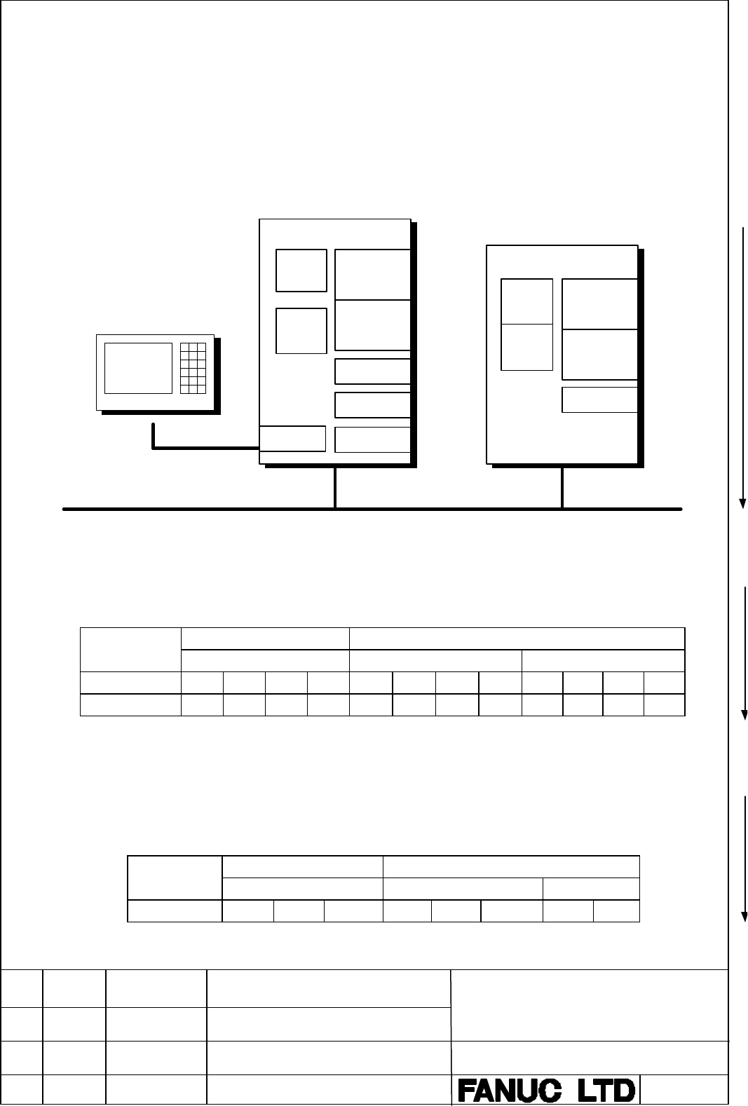
- Page 32. Specifications 2.1 System configuration 2.1.1 Hardware For 3-path control system, Sub CPU board and the option of 3 path control function with 2 CPU are need. (iii) Main CPU board PMC Servo axes Sub CPU board 4 Path-2 Servo axes Serial 4+4 9.5"LCD/10.4"LCD Path-1 Spindle 2 Path-3 Serial Spindle 2
- Page 42.1.4 DI/DO signal (1) Interface between CNC and PMC The interfaces for Path-3 between CNC and PMC are G2000∼G2255,F2000∼F2255. The interfaces for Path-1 and Path-2 are as same as two-path control. G0000∼G0255,F0000∼F0255 are for Path-1. G1000∼G1255,F1000∼F1255 are for Path-2. CNC system has one PMC
- Page 5(2) Direct DI/DO Address 7 6 5 4 3 2 1 0 (v) (vii) X000 X001 X002 X003 ESKIP -MIT2 #1 +MIT2 #1 -MIT1 #1 +MIT1 #1 ZAE #1 XAE #1 #1 X004 SKIP SKIP6 #1 SKIP5 #1 SKIP4 #1 SKIP3 #1 SKIP2 #1 SKIP8 #1 SKIP7 #1 X005 X006 X007 *DEC8 #2 *DEC7 #2 *DEC6 #2 *DEC5 #2 *DEC4 #2 *DEC3 #2 *DEC2 #2 *DEC1 #2 X008 *ESP
- Page 62.2 Programming 2.2.1 Program Programs are stored into each program memories for each path. The format of program is the FANUC standard format based on EIA format. To control 3-path system, waiting function, Synchronous/composite/superimposed control function and Spindle control function are provide
- Page 7(4) Parameters 7 6 5 4 3 2 1 0 8101 MWB [Data type] : Bit MWB A waiting M code is 0: Buffered. 1: Not buffered. Note) An M code is never buffered when the same M code is specified in the parameters 3411 to 3420 as the M code prevented from buffering. 8110 Waiting M code range (minimum value) 8111 Wa
- Page 8(6) Example When the no-wait signal (G1063.7) is set to 1 and M101 to M103 are specified as waiting M codes, the programs for each paths execute as following. Parameter setting : Parameter 8110 = 101 : Parameter 8111 = 103 Program for Path-1 Program for Path-2 Program for Path-3 O0100; O0200; O0300;
- Page 9(7) Alarms and messages No. Message Description 160 MISMATCH WAITING M-CODE (a) The commands have identical P values but different M codes. (b) The commands have identical M codes but different P values. (c) Both two-path and three-path wait are simultaneously executed. 161 ILLEGAL P OF WAITING (a)
- Page 102.2.3 Synchronous control and composite control (1) Overview 3-path control has three independent control paths. For example, it can be used to control three turrets of a multiple-turret lathe independently. Machining is performed by a path 2 program. Z2 Turret 2 X2 Workpiece 1 Workpiece 2 Z1 Z3 X1
- Page 11(2) Synchronous Control An axis in path 1 or path 2 can be synchronized with another axis in the same path or an axis in the other path. This is realized by issuing the same move commands for one axis (synchronous master axis) to another axis (synchronous slave axis). Using parameter SMRx (bit 0 of
- Page 12(3) Composite Control Move commands can be interchanged between an axis in path 1 or path 2 and an axis in the other path. In other words, when a machining program is executed for one path, actual machining can be performed with an axis in the other path. Coordinate systems can also be switched auto
- Page 13(4) Superimposed Control The superimposed control function adds the amount of movement of an axis (superimposed control master axis) to an axis (superimposed control slave axis) for which ordinary move commands are being executed. This function is similar to synchronous control but differs from it i
- Page 14(d) Feedrate Because the amount of movement of the master axis is added to that of the slave axis, the resulting speed of the slave axis may become much more larger than a normal speed (such as rapid traverse speed specified in a parameter). To solve this problem, it is necessary to set feedrates th
- Page 15(5) Signals (a) Synchronous control axis selection signals SYNC1-8
- Page 16(c) Composite control axis selection signal MIX1-8
- Page 17(e) Synchronous/composite/superimposed control under way signals SYN1O to SYN8O
- Page 18(6) Parameter 7 6 5 4 3 2 1 0 8160 NRS SPE [Data type] Bit SPE The synchronization deviation is: 0: The difference between the positioning deviation of the master axis and that of the slave axis. 1: The difference between the positioning deviation of the master axis and that of the slave axis plus t
- Page 197 6 5 4 3 2 1 0 8162 MUMx MCDx MPSx MPMx OMRx PKUx SERx SMRx [Data type] Bit axis SMRx Synchronous mirror-image control is: 0: Not applied. (The master and slave axes move in the same direction.) 1: Applied. (The master and slave axes move in opposite directions.) SERx The synchronization deviation
- Page 207 6 5 4 3 2 1 0 8163 SCDx SCMx SPSx SPMx MDXx [Data type] Bit axis MDXx In composite control, the current position (absolute/relative coordinates) display indicates: 0: Coordinates in the local system. 1: Coordinates in the other system under composite control. SPMx When synchronous control is start
- Page 217 6 5 4 3 2 1 0 8166 OVL MIX SYN (iii) [Data type] Bit SYN The interface of the synchronous control is: 0: Covered 3 paths. 1: Usual 2 paths interface. (Not covered 3rd path control) MIX The interface of the composite control is: 0: Covered 3 paths. 1: Usual 2 paths interface. (Not covered 3rd path
- Page 228181 Synchronization error limit of each axis (Synchronous or composite control) [Data type] Two-word axis [Unit of data] Unit of detection [Valid data range] 0 to 32767 When the synchronization deviation detected (SERx of bit #1 parameter No.8162 is set to 1), this parameter specifies the limit of
- Page 238184 Coordinates of reference point of an axis on the coordinate system of another composite control [Data type] Two-word axis [Unit of data] Increment system IS-A IS-B IS-C Unit Millimeter machine 0.01 0.001 0.0001 mm Inch machine 0.001 0.0001 0.00001 inch Rotation axis 0.01 0.001 0.0001 deg [Valid
- Page 248190 Rapid traverse rate of an axis under superimposed control [Data type] Two-word axis [Unit of data] [Valid data range] Valid data range Increment system Unit of data IS-A,IS-B IS-C Millimeter machine 1 mm/min 30 to 240000 30 to 100000 Inch machine 0.1 inch/min 30 to 96000 30 to 48000 Rotation ax
- Page 258193 Maximum cutting feedrate under superimposed control [Data type] Two-word [Unit of data] [Valid data range] Valid data range Increment system Unit of data IS-A,IS-B IS-C Millimeter machine 1 mm/min 30 to 240000 30 to 100000 Inch machine 0.1 inch/min 30 to 96000 30 to 48000 Rotation axis 1 deg/mi
- Page 26(7) Alarms and Messages If one of the alarms listed below occurs, it terminates synchronous, composite, and superimposed control for all axes. Number Message Description 225 Synchronous or composite control This alarm occurs under either of the following conditions(detected when synchronous, composi
- Page 272.3 Spindle speed control 2.3.1 General 3-path control has one spindle interface in each path, that is three interfaces as total. For example, (iii) a work fixed at one or two spindles can be machined by three tool posts and power tools in same time. Each spindle interfaces (first spindle, second sp
- Page 28(4) 2nd and 3rd spindle If 1st spindle is a serial spindle, 2nd and 3rd spindles are also able to use in a 3-path lathe. The 2nd and 3rd spindles are controlled by PMC signals (SIND#1,SIND2#1,SIND3#1,SIND#2,SI ND2#2,SIND3#2, SIND#3,SIND2#3,SIND3#3) or by the multi-spindle control function. If using
- Page 29(b) The relation between the path and the spindle feedback (the state in 3-spindle control and all spindles connected) SP1#1 SP2#1 SP1#2 SP2#2 SP1#3 SP2#3 PC1#1 PC2#1 PC1#2 PC2#2 PC1#3 PC2#3 Path 1 0 1 Path 2 0 1 Path 3 0 1 PC2SLC#1 PC2SLC#2 PC2SLC#3 SLPCA#1 SLPCB#1 SLPCA#2 SLPCB#2 SLPCA#3 SLPCB#3 1
- Page 30(6) Signals (a) Spindle command select signals 7 6 5 4 3 2 1 0 G0063 SLSPB#1 SLSPA#1 G1063 SLSPB#2 SLSPA#2 G2063 SLSPB#3 SLSPA#3 [Classification] Input signal [Function] Selects which spindle receives spindle command of which path. [Operation] Spindle command Spindle command Spindle command on path
- Page 31(b) Spindle feedback select signals 7 6 5 4 3 2 1 0 G0064 SLPCB #1 SLPCA #1 G1064 SLPCB #2 SLPCA #2 G2064 SLPCB #3 SLPCA #3 [Classification] Input signal [Function] Selects which spindle sends the feedback signal of the position coder to which path. [Operation] Spindles on path Spindles on path Spin
- Page 32(c) Spindle select signals 7 6 5 4 3 2 1 0 G0027 SWS3#1 SWS2#1 SWS1#1 G1027 SWS3#2 SWS2#2 SWS1#2 G2027 SWS3#3 SWS2#3 SWS1#3 [Classification] Input signal [Function] In the multi-spindle function, it is controlled that S command on CNC is output to which spindle. [Operation] SWS1#1 1: Spindle command
- Page 33(d) Spindle stop signals 7 6 5 4 3 2 1 0 G0027 *SSTP3#1 *SSTP2#1 *SSTP1#1 G1027 *SSTP3#2 *SSTP2#2 *SSTP1#2 G2027 *SSTP3#3 *SSTP2#3 *SSTP1#3 [Classification] Input signal [Function] In the multi-spindle function, each spindle on each path can be stopped individually by these signals. [Operation] *SST
- Page 34(e) 2nd position coder select signals 7 6 5 4 3 2 1 0 G0028 PC2SLC#1 G1028 PC2SLC#2 G2028 PC2SLC#3 [Classification] Input signal [Function] These signals select whether to use the feedback of the 2nd position coder. [Operation] PC2SLC#1 1: The feedback of the 2nd position coder is used on path 1. 0:
- Page 35(7) Parameter 7 6 5 4 3 2 1 0 3702 ECS ESS EAS ESI EMS [Data type] Bit EMS The Multi-spindle control function is: 0: Used. 1: Not used. ESI The Spindle positioning function is: 0: Used. 1: Not used. EAS The Spindle analog output function is: 0: Used on path 1, path 2, or path 3. 1: Not used. ESS The
- Page 367 6 5 4 3 2 1 0 3706 PCS [Data type] Bit PCS In 2-path or 3-path control, when Multi-spindle control is used on each path, the relation of the selected position coder and the signals SLPCA, SLPCB, and PC2SLC on each path is: 0: As the following table (a). 1: As the following table (b). (a) Parameter
- Page 37(b) Parameter PCS (No.3706#3)=1 SLPCA SLPCB PC2SLC#1 PC2SLC#2 PC2SLC#3 0 1 0 1 0 1 Path 1 1 0 PC1#1 PC2#1 (#1) 0 1 PC1#2 PC2#2 1 1 PC1#3 PC2#3 Path 2 1 0 PC1#1 PC2#1 (#2) 0 1 PC1#2 PC2#2 1 1 PC1#3 PC2#3 Path 3 1 0 PC1#1 PC2#1 (#3) 0 1 PC1#2 PC2#2 1 1 PC1#3 PC2#3 (PC1,2=Position coder 1,2) 2.3.3 Noti
- Page 382.4 Display and edit function 2.4.1 Path selection HEAD(G0063#0) and HEAD2(G0062#7) select which path’s screen is displayed. HEAD(G0063#0) HEAD2(G0062#7) Path 1 0 0 Path 2 1 0 Path 3 0 1 2.4.2 Common screen for whole paths Some screens exist on each path, for example, the parameter screen. And other
- Page 39(b) All position ACTUAL POSITION | | HEAD1 O12345678 N12345 |HEAD2 O12345678 N12345 |HEAD3 O12345678 N12345 (RELATIVE) (ABSOLUTE) | (RELATIVE) (ABSOLUTE) | (RELATIVE) (ABSOLUTE) U1-99999.999 X1-99999.999|U2-99999.999 X2-99999.999|U3-99999.999 X3- 99999.999 W1-99999.999 Z1-99999.999|W2-99999.999 Z2-9
- Page 40(3) Program edit screen PROGRAM | | HEAD1 O12345678 N12345 |HEAD2 O12345678 N12345 |HEAD3 O12345678 N12345 O12345678; |O12345678; |O12345678; N1 |N10 |N100 N2 |N20 |N200 N3 |N30 |N300 N4 |N40 |N400 | | | | | | | | | | | | | | | | | | | | | | | | | | EDIT **** *** *** 12:34:56 HEAD1 PROG CHK NEXT (OP
- Page 412.5 Tool post interference check 2.5.1 General Tool post interference check can decelerate and stop the two tool posts before the tool posts interfere with each other by an incorrect command. And alarms and DO signals are output. Tool post interference check is available for the interference between
- Page 42CNC checks interferenc Parallel axis e. Parallel axis 2 Parallel axis 1 Parallel axis 1 Facing axis Facing axis CNC does not check the interference of the surface which was surrounded by the dotted line in the above figure. The specifying in the surface of the dotted line is due to the setting of th
- Page 43n l (c) n s (a) Parallel axis 2 (b) Parallel axis 1 s l Facing axis The rectangular parallelepiped which composes one tool post is maximum three rectangular parallelepiped and each rectangular parallelepiped is defined by the former specifying of the rectangular parallelepiped. Therefore, in the exa
- Page 44Address #7 #6 #5 #4 #3 #2 #1 #0 F0292 ITFCA3 ITFCA2 ITFCA1 [Classification] output signals [Function] These signals indicate whether a movement command was executed that interference might occur between tool posts. [Operation] When each ITFCA* signal is 1, a movement command was executed that interf
- Page 4512504 IDRCH [Data type] Bit IDRCH The plane not to check interference is: 0: the minus side on the vertical plane of the facing axis (width axis) 1: the plus side on the vertical plane of the facing axis (width axis) 12505 Offset amount on the facing axis at the point (i) of the rectangular parallel
- Page 46[Data type] 2-word [Unit of data] Output unit [Valid data range] 0-±99999999 Setting offset amount on each axis at the pair of points ((i), (ii)) on max. 3 rectangular parallelepipeds ((a), (b), (c)) composing the tool post 1. The offset amount is the distance with signs from the machine reference p
- Page 4712580 DRCV2 DRCV1 DRCH [Data type] Bit DRCH The facing axes (width axes) of the interference check #1 (tool post 1 and 2) are: 0: same direction. 1: opposite direction. DRCV1 The parallel axes 1 (length axes) of the interference check #1 (tool post 1 and 2) are: 0: same direction. 1: opposite direct
- Page 4812581 Offset amount of the reference point on machine coordinates between the facing axes of the interference check #1 (tool post 1 and 2). 12582 Offset amount of the reference point on machine coordinates between the parallel axes 1 of the interference check #1 (tool post 1 and 2). 12583 Offset amo
- Page 492.6 Reverse function by manual handle 2.6.1 General This function enables executing a program forward or backward by manual handle in order to check the mistake of a program or the interference. (1) Checking mode (iii) For executing the forward and reverse movement by the manual handle, the mode is
- Page 502.6.2 Details (1) Control by manual handle (a) Program execution start After entering the checking mode, the program execution is begun. Then the synchronous operation of the manual handle is selected, the execution of the program in the checking mode is controlled by the pulse of the manual handle
- Page 51and it has possible to execute the program with the forward movement. If the signal to select the mode which the program is executed by handle turns off in the reverse mode, the execution of the program is changed to the forward movement and the program is executed independently of the manual handle
- Page 52(c) S and T-code A modal value of previous block is output. (5) Direction change prohibition The change of forward movement / reverse movement is prohibited. Please move the manual handle in the same direction as present direction. The direction change prohibition can be confirmed by output signal M
- Page 53Example) O0001 ; M5 S0 F0 ; G53 X0 Z0 ; (1) G1 W100 M3 S100 F1. ; (2) G0 U50. W50. ; (3) M2 ; [Forward movement] (1) G53 X0 Z0 (3) G0 U50 W50. (2) G1 W100. M3S100F1. [Reverse movement] (1) G53 X0 Z0 (3) G0 U50. W50. (2) G1 W100. M5S0F1. Therefore operate M,S,T codes in the reverse movement after con
- Page 54100% override speed. In thread cutting cycle, the manual handle is invalid at the time actually cutting thread, but in the other movements it is valid (d) Multiple command of auxiliary function Multiple command of auxiliary function can not be used with the retrace by manual handle function. The sec
- Page 556414 M-code of group A (4) 6415 M-code of group B (1) 6416 M-code of group B (2) 6417 M-code of group B (3) 6418 M-code of group B (4) 6419 M-code of group C (1) 6420 M-code of group C (2) 6421 M-code of group C (3) 6422 M-code of group C (4) 6423 M-code of group D (1) 6424 M-code of group D (2) 642
- Page 566445 M-code of group I (3) 6446 M-code of group I (4) 6447 M-code of group J (1) 6448 M-code of group J (2) 6449 M-code of group J (3) 6450 M-code of group J (4) 6451 M-code of group K (1) 6452 M-code of group K (2) 6453 M-code of group K (3) 6454 M-code of group K (4) 6455 M-code of group L (1) 645
- Page 576476 M-code of group Q (2) 6477 M-code of group Q (3) 6478 M-code of group Q (4) 6479 M-code of group R (1) 6480 M-code of group R (2) 6481 M-code of group R (3) 6482 M-code of group R (4) 6483 M-code of group S (1) 6484 M-code of group S (2) 6485 M-code of group S (3) 6486 M-code of group S (4) 648
- Page 58(b) DO signal 7 6 5 4 3 2 1 0 F0091 MRVSP MNCHG MRVMD [Classification] Input signal [Operation] MRVMD Reverse movement signal 0: The operation is forward movement. 1: The operation is reverse movement. MNCHG Direction change prohibition signal 0: Changing forward and reverse movement is available. 1
- Page 593. Specifications list for 2 CPU 3-path control Ο : Standard I : Option S : Function included in another option Item Specifications 16i-TA Controlled axis Max. controlled axes 12 axes (4 x 3path) I (Machine controlled axes are including Cs axes) Loader control - Controlled axis ( each path ) 2axes Ο
- Page 60required. Control axis detach I Least input increment 0.001mm, 0.001deg, Ο 0.0001inch Increment system 1/10 0.0001mm,0.0001deg, I 0.00001inch Flexible feed gear Optional DMR Ο Learning control - Preview repetitive control - Dual position feedback I Fine Acc. & Dec. control Ο HRV control Ο Inch/Metri
- Page 61DNC operation Reader/puncher interface is S required. Only for 1 path MDI operation Ο Schedule function Only for 1 path - Program number search Ο Sequence number search Ο Sequence number comparison and I stop Program restart I Tool retract and recover I Manual intervention and return Ο Buffer regist
- Page 62Helical interpolation Circular interpolation plus I max. 2 axes linear interpolation Hypothetical axis interpolation I Threading, synchronous cutting Ο Multiple threading Ο Threading retract I Continuous threading I Circular threading I Variable lead threading I Polygon turning I Polygon machining w
- Page 63Positioning by optimal acceleration I Linear acceleration/deceleration I after cutting feed interpolation Bell-shaped I acceleration/deceleration after cutting feed interpolation Linear acceleration/deceleration Feed per minute only I before cutting feed interpolation Feedrate override 0∼254% Ο 2nd
- Page 64Automatic coordinate system setting Ο Coordinate system shift Ο Direct input of coordinate system Ο shift Workpiece coordinate system G52 ∼ 59 I Workpiece coordinate system preset I Direct input of workpiece origin S offset value measured Manual absolute on and off Ο Direct drawing dimension I progr
- Page 65C language executor Max. 4MB I Conversational programming function for lathe Super CAP II T - Super CAP T - CAP I - CAP II - Symbolic CAP T - Auxiliary/Spindle speed function Auxiliary function M8-digit Ο 2nd auxiliary function B8-digit I Auxiliary function lock Ο High speed M/S/T/B interface Ο Wait
- Page 66Tool function/Tool compensation Tool function T7+1/T6+2 digits Ο ±6 digits 9/16 pairs Ο Tool offset pairs ±6 digits 32 pairs I ±6 digits 64 pairs I ±6 digits 99 pairs I Tool offset Ο Y-axis offset I Tool nose radius compensation I Tool geometry/wear compensation I Tool life management I Addition of
- Page 6763 Ο 125 I Number of registerable programs 200 I 400 I 1000 I Part program editing Ο Program protect Ο Background editing I Extended part program editing I Playback I Machining time stamp I Setting and display Status display Ο Clock function Ο Current position display Ο Program display Program name
- Page 68Background graphic without CAP - Optional path name display Only for 2 and 3 path Ο Servo setting screen Ο Spindle setting screen Only for serial interface S Servo waveform display Graphic display circuit is S required. Display of hardware and software Ο configuration Periodic maintenance screen Ο M
- Page 69DNC1 control Uploading/downloading a - part program,Reading/writing CNC data,Transfer of PMC data,Memory operation control,etc. DNC2 control Only for 1 path - Uploading/downloading a part program,Reading/writing CNC data,Transfer of PMC data,Memory operation control,etc. Modem card control Ο Externa