FS 16i/18i/21i-MB/TB, Expansion Tool Management Function Additional Manual Page 10
Additional Manual
2003.6.30
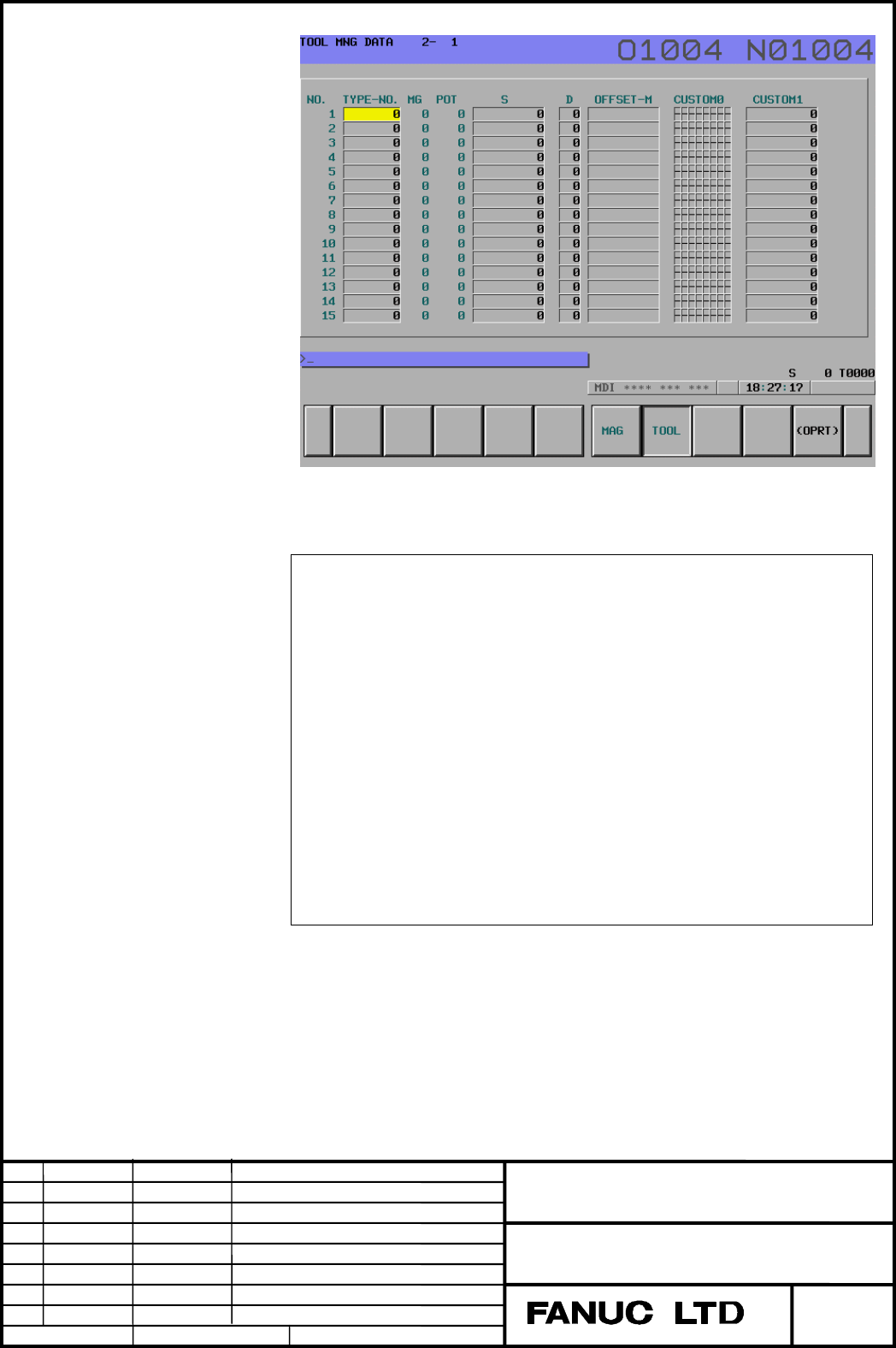
Example2 page2
3.In case of G10 reconfiguration.
(Before reconfiguration)
G10L77P3; Customization of the tool management data table
screen
N1 R1; No. 1 is No.
N2 R2; No. 2 is TYPE-NO.
N3 R3; No. 3 is MG.
N4 R4; No. 4 is POT.
N5 R-1; Terminated.
G11; Mode cancel
(After reconfiguration)
G10L77P3; Customization of the tool management data table
screen
N1 R5; No. 1 is T-INFO.
N3 R6; No. 3 is L-COUNT.
N4 R7; No. 4 is MAX-LIFE.
N5 R-1; Terminated.
G11; Mode cancel
Before reconfiguration, the screen is displayed as order of “NO., TYPE-NO.,
MG, POT”. After reconfiguration, it is displayed as order of “T-INFO, blank
column, L-COUNT, MAX-COUNT”.
Edit
10/26
Data Signature
Description
FANUC Series 16i/18i/21i-MB/TB
Expansion Tool Management Function
A-79171
Drawing No.
Title
Page
Contents Summary of FS 16i/18i/21i-MB/TB, Expansion Tool Management Function Additional Manual
- Page 1FANUC Series 16i/18i/21i-MB/TB Expansion Tool Management Function Specifications Contents 1 GENERAL .............................................................................................................................................................2 1.1 Customization of a tool management da
- Page 21 GENERAL This function adds the following feature for the tool management function. 1. Customization of a tool management data item display 2. Setting of a name of the spindle position or the wait position 3. Setting of the customizing data with a decimal point 4. Protection of a various tool manag
- Page 31.1 Customization of a tool management data item display This function realizes to specify display item (type-no, tool information, life counter etc.) and display position on the tool management data table screen by G10 command. Format Format G10L77P3; Customization mode of the tool management data
- Page 4(2) 7 soft key type : Max. 10 items 7 soft key type : soft key is (5 + 2) type · Tool management data table screen display position number(N_) Specify the position number of the tool management data table screen. ・ In case of 12 soft key type, display position number is starting from left on the too
- Page 5∙Machining center system and lathe system common items Display R Item Remarks width -1 Terminal code - 0 Blank 10 1 NO. 4 2 Type-NO. 8 3 MG 3 4 POT 4 5 T-INFO 10 6 L-COUNT 10 7 MAX-LIFE 10 8 NOTICE-L 10 9 L-STATE 10 10 S (Spindle speed) 10 11 F (Feedrate) 10 ∙Machining center system and also Machine
- Page 6∙Lathe system Display R Item Remarks width 40 TG 4 41 TW 4 42 OFFSET-X 10 43 OFFSET-Z 10 44 OFFSET-R 10 ∙Tool nose radius compensation 45 TIP 10 46 OFFSET-Y 10 Y axis offset 47 OFFSET-B 10 B axis control 48 GEOM(X) 10 ∙Tool geometry/wear compensastion 49 WEAR(X) 10 50 GEOM(Z) 10 51 WEAR(Z) 10 52 GEO
- Page 7NOTE When G10 L77 P3 is normal termination, the power must be turned off before operation is continued. Example 1.In case of 12 softkey type, tool compensasion memory A. G10L77P3; Customization of the tool management data table screen N1 R1; No. 1 is No. N2 R2; No. 2 is TYPE-NO. N3 R3; No. 3 is MG.
- Page 8Example1 page1 Example1 page2 Title FANUC Series 16i/18i/21i-MB/TB Expansion Tool Management Function Drawing No. A-79171 Page Edit Data Signature Description 8/26 2003.6.30
- Page 92.In case of 12 softkey type, tool compensasion memory A. G10L77P3; Customization of the tool management data table screen N1 R1; No. 1 is No. N2 R2; No. 2 is TYPE-NO. N3 R3; No. 3 is MG. N4 R4; No. 4 is POT. N5 R5; No. 5 is T-INFO. N6 R6; No. 6 is L-COUNT. N7 R7; No. 7 is MAX-LIFE. N8 R8; No. 8 is
- Page 10Example2 page2 3.In case of G10 reconfiguration. (Before reconfiguration) G10L77P3; Customization of the tool management data table screen N1 R1; No. 1 is No. N2 R2; No. 2 is TYPE-NO. N3 R3; No. 3 is MG. N4 R4; No. 4 is POT. N5 R-1; Terminated. G11; Mode cancel (After reconfiguration) G10L77P3; Cust
- Page 11NOTE ・ This function is enabled when the TDC(No.13201#0) is set to 1. ・ The max. setting pages is 20. ・ This function is necessary to terminal code(-1). ・ If any item required the option is specified without the option, the item is displayed as blank space in the screen. ・ The item after the termina
- Page 121.2 Setting of a name of the spindle position and the wait position The spindle position and the wait position are displayed by the number such as 11, 12, 13 etc. at MG item of the tool management data table screen. This function displays user’s setting name of any 3 characters set by G10 command. F
- Page 13Example Specify the name of the spindle position(111) is “SP1”, the name of the wait position (121) is “WT1”. G10L77P4; Setting of a name of the spindle and the wait position mode N111; Specify the spindle position 1 P1 R83; ASCII code of “S” is 53h P2 R80; ASCII code of “P” is 50h P3 R49; ASCII cod
- Page 141.3 Setting of the customizing data with the decimal point This function can set customizing data with the decimal point by G10 command Format Format G10L77P5; Specify the decimal point to the customizing data N_R_; G11; Mode cancel Meaning of command N_: Number of the customizing data( 1 to 20) R_:
- Page 15Setting 3 digits below decimal point of the customizing data1, data2 Title FANUC Series 16i/18i/21i-MB/TB Expansion Tool Management Function Drawing No. A-79171 Page Edit Data Signature Description 15/26 2003.6.30
- Page 161.4 Protection for various tool management data by the key signal This function is possible to protect tool management data by the key signal. Signal Tool management data protection signal TKEY0 to TKEY5
- Page 171.5 Selecting of the life counting cycle of tool life value This function enables the selection of each tool for life counting cycle unit (every 1 second or 8m second). Selecting of the life count cycle Selection of the life counting cycle is specified by #5 bit of tool information. Item Content Dat
- Page 181.6 Output to external device Input/output to the external devices is possible by the [ALL I/O screen] or [tool management screen] when the I/O device number is 4, 6. Select to the
screen and press soft key [ALL IO]. Press the continuous menu key some times until the above screen is display - Page 192 SYSTEM VARIABLE The following tool management data, the tool of spindle position and the next tool which is commanded by T code, is possible to read by Custom Macro. Number Item #8401 Data number #8402 Tool type number #8403 Tool life counter #8404 Maximum of tool life #8405 Previous notice tool l
- Page 20Using G10 format The address “R” can not have a value below decimal point. Therefore, in input of customizing data with decimal point by G10, the value of address “R” must be considered about the number of digits below the decimal point. Note) This restriction is G10 command only. System variables #
- Page 213 ALARM Alarm and message Warning message Contents INPUT IS REJECTED When the TIM (#1 of tool information) is 0, the REV(#5 of tool information) is specified. WRITE PROTECT Data input is invalid because of memory protect signal. Number Message Description 5312 ILLEGAL COMMAND IN The mistake is found
- Page 224 PARAMETER #7 #6 #5 #4 #3 #2 #1 #0 13201 TDB TDC [Data type] Bit TDC Customization of a tool management data screen item function is 0: Disabled 1: Enabled TDB In the tool management function, tool information is displayed by 0: Symbol notation 1: 1/0 notation. NOTE ・ When this parameter is set, th
- Page 235 Option parameter NOTE This function needs the following option functions. FANUC Series 16i/18i/21i/160i/180i/210i-MB/TB - Tool management function or Tool management function 240 pairs or Tool management function 1000 pairs - Expansion tool management function Addition condition This function need
- Page 246 PMC WINDOWS A PMC window for tool management expansion is prepared as follows. List of PMC window functions No. Function Function code Type Read/Write 1 Reading a decimal point of the customizing data 392 Low R Title FANUC Series 16i/18i/21i-MB/TB Expansion Tool Management Function Drawing No. A-7
- Page 256.1 Reading a decimal point of the customizing data [Description] This function reads a decimal point of the customizing data. The number of reading data is changed by “Additional customized data on tool management function” option. If this option exists, the number of reading data is 20. If this op
- Page 26[Output structure] 0 (Function code) 392 2 (Completion code) Refer to above description 4 (Data length) 4, 20 6 (Data number) - 8 (Data attribute) - 10 Decimal point of the customizing data1 11 Decimal point of the customizing data2 12 Decimal point of the customizing data2 13 Decimal point of the c