FANUC AC Servo Software 90B3 / 90B7 Series Angle based Learning Control Specification Manual Additional Manual Page 3
Additional Manual
Title 90B3 / 90B7 Angle Based
Learning Control Specification Manual
Draw No.
A - 63639E - 119
01 ’04.02.23 K.Maeda Newly designed Sheet 03
Edit Date Design Description / 10
2. Configuration
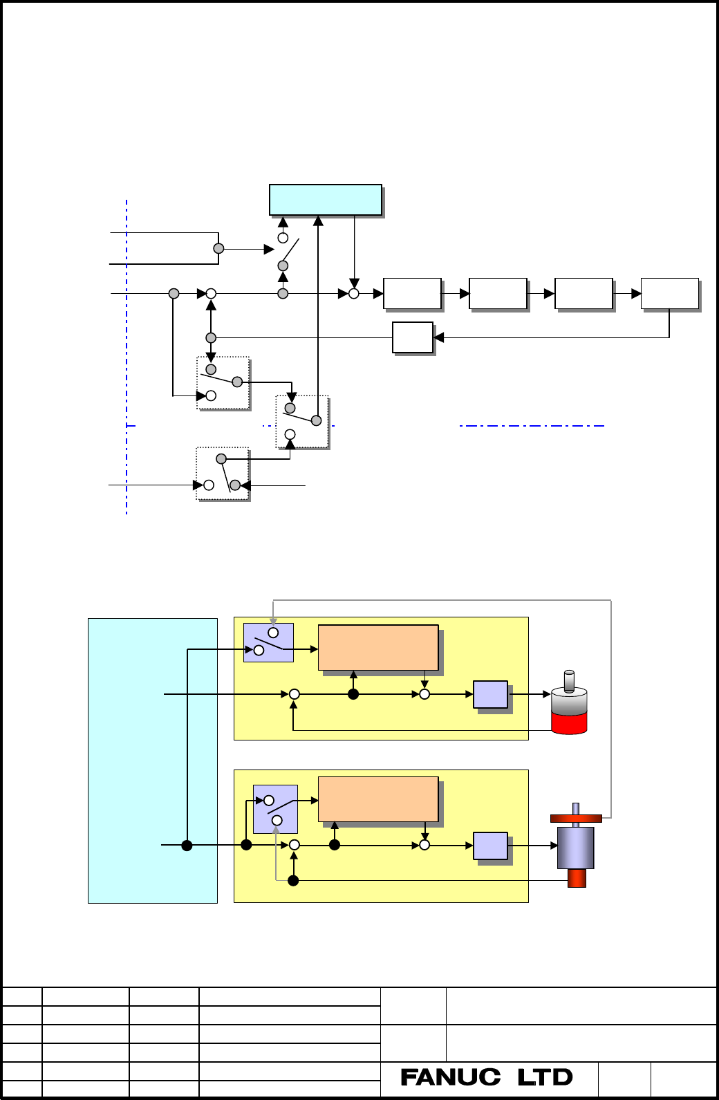
The start of Angle based Learning control are the usual way to synchronize the start of High-speed cutting
(G05) and the new way to synchronize the start of PMC signal.
It is necessary to refer to angle as a standard. You can select position feedback or position command as this
reference position. And you can select feedback or command of the other axis. In this case, it is necessary to
give feedback or command of reference axis to odd axis.
Refer to Fig.2-1 Angle based Learning control configuration diagram.
Fig.2-1 Angle based Learning control configuration diagram
2-1. Application examples
(1) Variable Spindle speed (G05)
In case of variable spindle speed with fitting linear axis amplitude, Angle based Learning control can be used.
Because linear axis refer to spindle command, you must give spindle command to the dummy axis.
Angle based
Learning control
Motor
Velocity
control
Current
control
Command
G05
PMC G320
Reference
command
Reference feedback
Reference
position
Feedback
Start
signal
CNC Servo
L-axis / M-axis select
N2227#5(M)
Command / FB select
N2227#4(L)
L-axis (odd axis)
FFG
M-axis (even axis)
+
+
−
−−
−
Position
control
+
Learning
controller
Learning
controller
Kp
Kp
Kp
Kp
Position error
Dummy
Command
Command
Rotary axis
Command
Linear axis
Rotary axis
Servo control
G05 command
Servo
Motor
Built-in
Spindle
Outer
detector
CNC
Spindle control (Cs control)
Position error
Learning
controller
Learning
controller
Contents Summary of FANUC AC Servo Software 90B3 / 90B7 Series Angle based Learning Control Specification Manual Additional Manual
- Page 1FANUC AC SERVO SOFTWARE 90B3 / 90B7 Series Angle based Learning Control Specification Manual 1. Overview 2. Configuration 3. Application servo software series / edition 4. Parameters 5. PMC signals 6. Alarm (CAUTION) The contents of this manual may be changed as a result of improvements to the servo
- Page 21. Overview We have developed Angle based Learning control to usual Time based Learning control. This function merit is the following. • This function provides not time but angle as Learning period. Therefore this function can apply to variable time period application that is difficult to realize by
- Page 32. Configuration The start of Angle based Learning control are the usual way to synchronize the start of High-speed cutting (G05) and the new way to synchronize the start of PMC signal. It is necessary to refer to angle as a standard. You can select position feedback or position command as this refe
- Page 4You can apply Spindle Learning control with angle based to rotary axis. 2) Application example in Flexible Synchronous Control Synchronous shaving machine CNC Servo control or Spindle control FSC Learning Learning Master axis controller controller Command Kp Kp Position error Gear Ratio Reference Sl
- Page 53. Application servo software series / edition • 90B7 / 13(M) or later • 90B3 / 14 (N) or later (next edition planning) 4. Parameters Function bit #7 #6 #5 #4 #3 #2 #1 #0 2008 (FS16i ) SLEN 1952 (FS15i ) SLEN (#5) Learning control is (L-axis only) 0: not available. 1: available. (Option) #7 #6 #5 #4
- Page 6♦ Relation between Angle based Learning controller and Parameters N2243 N2244 Fx Delayed Memory Convert Convert Reference Position N2246 One rotation = N2241×N2242 N2247 Gx N2248 N2249 G05 or G320 + Position error + HRV control *1 Fx : Learning band. The higher you set Leaning band, precision is hig
- Page 7We suggest that you select minimum time period as the quotient of (Angle based Learning period) divided by (delayed memory number) is integer. 2244 (FS16i ) Learning frequency band 2657 (FS15i ) (Setting range) Case of sampling 1msec, from 0 to 350 Case of sampling 0.5msec, from 0 to 700 (Setting un
- Page 82250 (FS16i ) Delay compensation 2663 (FS15i ) (Setting range) from –32767 to +32767 (Plus is forward, Minus is delay) (Setting unit) nsec When reference to M-axis (M-axis : N2227#5 = 1), one sampling is delayed. Angle based Learning controller compensates sampling delay of reference position by thi
- Page 95. PMC signal If you input the following PMC signal, Angle based Learning control starts and finishes at point of any time without G05. This function can be used in Series 16i –B with supported General purpose DI/DO. #7 #6 #5 #4 #3 #2 #1 #0 G0320 SVDI08 SVDI07 SVDI06 SVDI05 SVDI04 SVDI03 SVDI02 SVDI
- Page 106. Alarm In case that there is a problem in parameter setting, the following "PARAMETER INCORRECT" displays. Alarm Parameter No. Parameter No. derail No. (FS15i ) (FS16i ) Cause Measures 2402 2241 Case that the quotient 1) Minimum time period is 2242 which divides Angle increased. based Learning per