FS 16i/18i/21i-MB/TB Trouble Diagnosis Specifications Additional Manual Page 13
Additional Manual
A-78500E
Edit
Apprv.
Desig.
Sheet
Title
Draw
No.
12/17
Date
Design
Descri
p
tion
Date
FANUC Series 16i /18i /21i -MB/TB
Trouble Diagnosis
Specifications
2001.07.02
M.Kobayashi H.Kochiya
02 2001.10.19 Exchan
g
e Bit ma
p
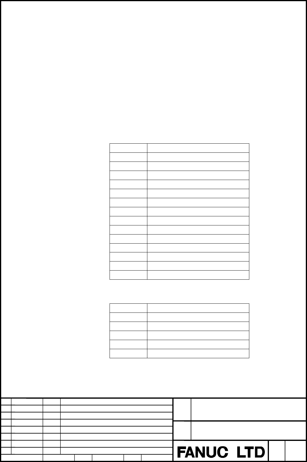
4.2.Operation
Data Setting
Move cursor by Cursor key and input number by MDI key and press input key [INPUT] to
set data.
AXIS: In case of servo axis, input control axis number.
(Example) Set "1" for first servo axis.
In case of spindle axis, input "10 + spindle number".
(Example) Set "11" for first spindle axis.
DATA KIND: Input data number value according to the following table.
- Data of Servo motor
Data number Data
1 Accumulated command pulse (pulse)
2 Accumulated feedback pulse (pulse)
3 Position error (pulse)
4 Reference counter (pulse)
5 Actual speed (min
-1
)
6 Command current (%)
7 Thermal simulation data (%)
8 Torque (%)
9 Disturbance torque (%)
10 Optional data
11 R-phase current (%)
12 Effective current (%)
13 Pulse coder AMR data
14 Optional data 2
- Data of Spindle motor
Data number Data
15 Actual speed (min
-1
)
16 Load meter (%)
17 Position error (pulse)
18 Actual speed (min
-1
) (80msec)
19 Load meter (%) (80msec)
Contents Summary of FS 16i/18i/21i-MB/TB Trouble Diagnosis Specifications Additional Manual
- Page 1TECHNICAL REPORT (MANUAL) No. TMN02/043E Date: May 8, 2002 General Manager of Software Development Center FANUC Series 16i/18i/21i-MB/TB Trouble diagnosis FANUC Series 16i/18i/21i-MB/TB Machine alarm diagnosis 1. Communicate this report to the destinations marked with ○: Your information ○ GE Fanuc-
- Page 2FANUC Series 16i/18i/21i-MB/TB Trouble Diagnosis Specifications 1. OUTLINE .......................................................................................................................................2 2. TROUBLE DIAGNOSIS GUIDANCE SCREEN ...................................................
- Page 31.Outline Investigating the cause of Servo/Spindle/CNC alarms becomes easier by diagnosis according to the guidance message. And when the thermal simulation or disturbance torque of servo axis exceeds the trouble forecast level, a trouble forecast signal can be output. Step of diagnosis 1. Answer th
- Page 43.Finaly, the guidance message in the trouble diagnosis guidance screen shows the probable cause of alarm and the method to remove the problem. FANUC Series 16i /18i /21i -MB/TB Title Trouble Diagnosis Specifications Draw No. A-78500E 02 2001.10.19 Exchange Bit map Edit Date Design Description Sheet
- Page 52.Trouble diagnosis guidance screen The trouble diagnosis guidance screen displays the guidance message to investigate the cause of an alarm. 2.1.Display Display procedure 1. Press function key [Message]. 2. Press the continuous menu key [>] and press soft key [GUIDE]. Trouble Code Contents of troub
- Page 62.2.Operation Change of Guidance [ YES ]/[ NO ] : Check contents of guidance message, and, answer by pressing soft key [ YES ] or [ NO ]. Then the next guidance message is displayed. In some cases CNC automatically checks and judges contents of guidance. In this case the next guidance message is aut
- Page 73.Trouble Diagnosis Monitor Screen Trouble Diagnosis Monitor Screen memorizes and displays servo/spindle monitor information for investigating servo/spindle alarm. Three kinds of data, "Data when the alarm occurs", "Data just before the alarm occurs", "Current data" can be selected and displayed. 3.
- Page 83.2.Data displayed in Monitor Screen Displayed data in Monitor screen is showed below. Display range is the range which can be displayed on screen and not capacity of system. 1) Data of servo motor Data (Unit) Data type Display range Required parameter Accumulated command pulse (pulse) 1 Word ±99999
- Page 91) Data of spindle motor Data (Unit) Data type Display range Required parameter Operation mode Character ***** Gear select command Character ***** Command pulse (pulse) 2 Word ±99999999 Command speed (min-1) Note 1) 1 Word -32768 - +32767 No.4020(Main) / No.4196(Sub) -1 Spindle speed (min ) 2 Word ±
- Page 103.3.Operation Display of Servo monitor data Servo monitor information is switched by pressing soft key [ NEW ]/[ OLD ]/[CURRNT]. Soft key [ NEW ] and [ OLD ] is displayed alternately. [ NEW ] : Data when the alarm occurs [ OLD ] : Data just before the alarm occurs [CURRNT] : Current data [MON_SP] :
- Page 11Display of Spindle monitor information Spindle monitor information is switched by pressing soft key [ NEW ]/[ OLD ]/[CURRNT]. Soft key [ NEW ] and [ OLD ] is displayed alternately. [ NEW ] : Data when the alarm occurs [ OLD ] : Data just before the alarm occurs [CURRNT] : Current data [MON_SV] : Ser
- Page 124.Trouble diagnosis parameter screen Data type, data unit and trouble forecast level in the trouble diagnosis graphic screen are set in Trouble Diagnosis Parameter Screen. 4.1.Display Display procedure 1. Press function key [Message]. 2. Press the continuous menu key [>] and press soft key [W.GRPH].
- Page 134.2.Operation Data Setting Move cursor by Cursor key and input number by MDI key and press input key [INPUT] to set data. AXIS: In case of servo axis, input control axis number. (Example) Set "1" for first servo axis. In case of spindle axis, input "10 + spindle number". (Example) Set "11" for first
- Page 145.Trouble Diagnosis Graphic Screen Servo/spindle data is automatically memorized for several seconds before alarm occurs and display and waveform of data can be displayed in Trouble Diagnosis Graphic Screen. Maximum 2 kinds of data are displayed in the same time. 5.1.Display Display procedure 1. Pre
- Page 155.2.Operation Change of position and magnification When Soft key [G-ADJ.] is pressed, the following soft keys appear. [<] [W.PRM ] [G-ADJ. ] [TRB_LV] [ ] [(OPRT)] [ ] ↓ [<] [ TIME→] [ TIME←] [H-DOBL] [H-HALF] [(OPRT)] [>] ↓ [<] [ CH-1↑ ] [ CH-1↓ ] [V-DOBL] [V-HALF] [(OPRT)] [>] ↓ [<] [ CH-2↑ ] [ CH-
- Page 166.Trouble Forecast Level Setting Screen (only for servo axis) Trouble forecast level is set in this screen. Two trouble forecast levels, thermal simulation and disturbance torque, can be set. 6.1.Display Display procedure 1. Press function key [Message]. 2. Press the continuous menu key [>] and pres
- Page 176.2.Operation Setting Trouble forecast level 1. Select thermal simulation or disturbance torque by page keys [Page↑]/[Page↓]. 2. Select axis by cursor keys [↑]/[↓]. 3. Input numerical value by MDI key and press [INPUT] key. Trouble forecast level is input into parameter No.8860 and 8861. Change of T
- Page 187.Parameter No. 7 6 5 4 3 2 1 0 8850 MDG Data type: bit MDG Trouble diagnosis function is: 0:Available. 1:Not available. No. 7 6 5 4 3 2 1 0 8853 TRS8 TRS7 TRS6 TRS5 TRS4 TRS3 TRS2 TRS1 Data type: bit TRS1 - TRS8 Trouble forecast is: 0:Not available. 1:Available. No. 8860 Trouble forecast level for