SYNCHRONOUS BUILT-IN SERVO MOTOR Dis series Descriptions Page 71
Descriptions
B-65332EN/01 HANDLING, DESIGN, AND ASSEMBLY 2.MECHANICAL DESIGN
- 55 -
2.1 MOUNTING MOTORS AND ENCODERS
2.1.1 Mounting Rigidity and Noise Protection
The Dis series motor is controlled using only a feedback signal from
the rotary encoder. This means that if the mounting rigidity of the
rotary encoder is insufficient, a feedback signal can pick up noise such
as mechanical vibration, resulting in a problem such as degraded
precision and uncontrollability. Be sure to mount a rotary encoder
with a high rigidity so that it does not pick up peripheral vibration. Set
the rigidity (natural frequency) of the head mounting portion to 2 kHz
or more as a guideline. Moreover, ensure that a rotary encoder is
mounted with the specified precision.
If a feedback signal from the rotary encoder picks up noise from
another electric system, a problem similar to the problems mentioned
above can occur. Ensure that the feedback signal cable is sufficiently
shielded and grounded, and that the feedback signal cable does not run
cross or along with the motor power line. a
2.1.2 Dis series motor and Rotary encoder Directions
To drive a Dis series motor normally, the positive direction of the Dis
series motor and the positive direction of the rotary encoder must
atch each other. m
CAUTION
If the direction of the Dis series motor does not
match the direction of the rotary encoder, the motor
can become uncontrollable in the worst case. In
mechanical design and assembly, ensure the
matching of the directions.
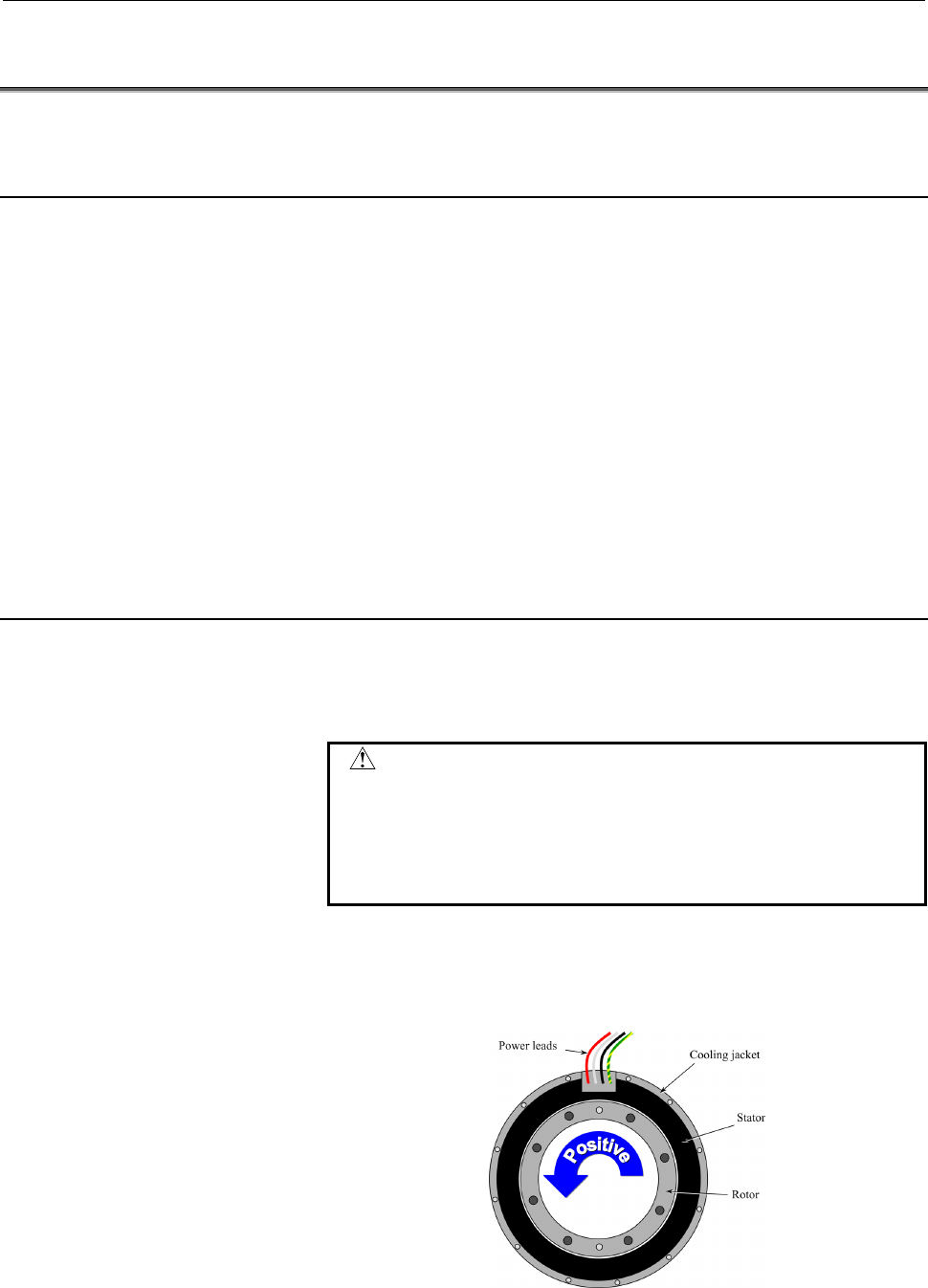
Positive direction of Dis series motor
Positive direction of Dis series motor is, counterclockwise of rotor
viewing from power leads side.
Contents Summary of SYNCHRONOUS BUILT-IN SERVO MOTOR Dis series Descriptions
- Page 1GE Fanuc Automation Europe Descriptions Manual Computer Numerical Controls Fanuc Synchronous Built-In Servo Motors Dis Series -B--65332EN/01 TECHNOLOGY AND MORE
- Page 2FANUC SYNCHRONOUS BUILT-IN SERVO MOTOR Dis series DESCRIPTIONS B-65332EN/01 © FANUC LTD, 2005
- Page 3FOR USERS Before getting started Read this manual thoroughly before using FANUC SYNCHRONOUS BUILT-IN SERVO MOTOR Dis series. It contains many important items. Do not try operation not described in this manual without permission. Otherwise, your motor may get into trouble. If it is unavoidable to ope
- Page 4B-65332EN/01 SAFETY PRECAUTIONS SAFETY PRECAUTIONS This "Safety Precautions" section describes the precautions which must be observed to ensure safety when using FANUC synchronous built-in servo motors. Users of any motor model are requested to read this manual carefully before using the synchronous
- Page 5SAFETY PRECAUTIONS B-65332EN/01 1.1 DEFINITION OF WARNING, CAUTION, AND NOTE This manual includes safety precautions for protecting the user and preventing damage to the machine. Precautions are classified into Warning and Caution according to their bearing on safety. Also, supplementary information
- Page 6B-65332EN/01 SAFETY PRECAUTIONS 1.2 WARNING WARNING - Be safely dressed when handling a motor. Wear safety shoes or gloves when handling a motor as you may get hurt on any edge or protrusion on it or electric shocks. - Any person having a medical apparatus must keep at least 30 cm away from any roto
- Page 7SAFETY PRECAUTIONS B-65332EN/01 WARNING - Do not touch a motor with a wet hand. A failure to observe this caution is vary dangerous because you may get electric shocks. - Before starting to connect a motor to electric wires, make sure they are isolated from an electric power source. A failure to obs
- Page 8B-65332EN/01 SAFETY PRECAUTIONS WARNING - Do not touch any terminal of a motor for a while (at least 5 minutes) after the power to the motor is shut off. High voltage remains across power line terminals of a motor for a while after the power to the motor is shut off. So, do not touch any terminal or
- Page 9SAFETY PRECAUTIONS B-65332EN/01 1.3 CAUTION CAUTION - Keep electronic devices and magnetic media away from any rotor. Bring an electronic device such as a personal computer, camera, or cellular phone or magnetic media such as a magnetic card or disk near a rotor may cause a failure or damage. - FANU
- Page 10B-65332EN/01 SAFETY PRECAUTIONS 1.4 NOTE NOTE - Do not step or sit on a motor. If you step or sit on a motor, it may get deformed or broken. Do not put a motor on another unless they are in packages. - When storing a motor, put it in a dry (non-condensing) place at room temperature (0 to 40 °C). If
- Page 11SAFETY PRECAUTIONS B-65332EN/01 NOTE - Do not apply a commercial power source voltage directly to a motor. Applying a commercial power source voltage directly to a motor may result in its windings being burned. Be sure to use a specified amplifier for supplying voltage to the motor. - Before using a
- Page 12B-65332EN/01 PREFACE PREFACE This manual covers information on the following models: FANUC SYNCHRONOUS BUILT-IN SERVO MOTOR Dis series D3000/150is D2100/150is D1500/200is D1200/250is D370/300is D260/600is D260/300is D110/300is D85/400is CAUTION Handling or installing the motor incorrectly may not on
- Page 13PREFACE B-65332EN/01 1.1 ORGANIZATION OF THIS MANUAL This manual is mainly divided into the following five chapters: I. SPECIFICATIONS Contains information about the specifications of synchronous built-in servo motors such as torque versus speed diagrams, external dimensions, and cooling conditions.
- Page 14B-65332EN/01 PREFACE 1.2 ACCEPTANCE AND STORAGE WARNING Mishandling a rotor may be highly dangerous, resulting in a fatal accident. Read and thoroughly understand the cautions on the next page and Part III, "HANDLING, DESIGN, and INSTALLATION," before handling the rotor and strictly observe the caut
- Page 15PREFACE B-65332EN/01 1.3 HANDLING A ROTOR (CAUTIONS) WARNING 1 Mishandling a rotor may be highly dangerous, resulting in a fatal accident. Read and thoroughly understand these cautions and Part III, "HANDLING, DESIGN, and INSTALLATION," before handling the rotor and strictly observe the cautions whe
- Page 16B-65332EN/01 PREFACE FANUC accepts no liability for any damage such as corruption or failure of an item due to magnetic fields. • Watches, cellular phones, magnetic cards, and other portable items • Magnetic tapes, floppy disks, MO disks, and other magnetic media • Cameras, personal computers, and o
- Page 17I. SPECIFICATION
- Page 18
- Page 19B-65332EN/01 SPECIFICATIONS 1.OVERVIEW 1 OVERVIEW Parts supplied by FANUC The following shows a typical system configuration of the FANUC SYNCHRONOUS BUILT-IN SERVO MOTOR Dis series. FANUC supplies the following parts according to the system configuration of your machine: - CNC system (CNC, PMC, amp
- Page 201.OVERVIEW SPECIFICATIONS B-65332EN/01 FANUC does not supply parts other than listed above. Use parts manufactured by 3rd parties as required. NOTE 1 Select a rotary encoder which meets the FANUC specifications. For details, see Part II, "CONFIGURATIONS AND SELECTION." 2 FANUC does not currently sup
- Page 21B-65332EN/01 SPECIFICATIONS 2.SPECIFICATIONS 2 SPECIFICATIONS -5-
- Page 222.SPECIFICATIONS SPECIFICATIONS B-65332EN/01 2.1 TERMS USED IN THE SPECIFICATION LIST AND SPEED DIAGRAMS - Cooling method There are the following methods for cooling a stator: Liquid cooling and no cooling. Air cooling is also applicable. - Maximum speed Maximum speed of the motor. You can run the m
- Page 23B-65332EN/01 SPECIFICATIONS 2.SPECIFICATIONS - Torque constant Torque obtained when 1 Arms flows for one phase. The following expression can be satisfied: [force constant] * [continuous current] = [continuous force]. This expression may not be satisfied due to saturated magnetic field, however. - Nu
- Page 242.SPECIFICATIONS SPECIFICATIONS B-65332EN/01 2.2 SPECIFICATION LIST *1 Model Items Unit D3000/150is D2100/150is D1500/200is D1200/250is A06B-0487-B400 A06B-0487-B300 A06B-0486-B300 A06B-0485-B500 Spec.No. - A06B-0487-B402 A06B-0487-B302 A06B-0486-B302 A06B-0485-B502 2 Cooling condition * - LC NC LC
- Page 25B-65332EN/01 SPECIFICATIONS 2.SPECIFICATIONS *1 Model Unit Items D370/300is D260/600is D260/300is D110/300is A06B-0484-B400 A06B-0484-B310 A06B-0484-B300 A06B-0484-B100 - Spec. No A06B-0484-B402 A06B-0484-B312 A06B-0484-B302 A06B-0484-B102 LC NC LC NC LC NC LC NC - Cooling condition *2 300 600 300 3
- Page 262.SPECIFICATIONS SPECIFICATIONS B-65332EN/01 *1 Model Items Unit D85/400is A06B-0483-B200 Spec. No. - A06B-0483-B202 2 Cooling condition * - LC NC 400 Max. speed min-1 (200) Upper speed for the 260 min-1 max. torque (130) 85 Rated Max. (85) torque Nm 35 17 *3 Cont. *4 (35) (17) 2.4 Rated Max. (1.2)
- Page 27B-65332EN/01 SPECIFICATIONS 2.SPECIFICATIONS 2.3 TORQUE-VERSUS-SPEED DIAGRAMS AND OUTPUT-VERSUS-SPEED DIAGRAMS D3000/150is (A06B-0487-B400/-B402, 400V) D3000/150is (A06B-0487-B400/-B402, 200V) NOTE The maximum output indicates the rated maximum output and is not data for PSM selection. For PSM selec
- Page 282.SPECIFICATIONS SPECIFICATIONS B-65332EN/01 D2100/150is (A06B-0487-B300/-B302, 400V) D2100/150is (A06B-0487-B300/-B302, 200V) NOTE The maximum output indicates the rated maximum output and is not data for PSM selection. For PSM selection, see Part II, "CONFIGURATIONS AND SELECTION." - 12 -
- Page 29B-65332EN/01 SPECIFICATIONS 2.SPECIFICATIONS D1500/200is (A06B-0486-B300/-B302, 400V) D1500/200is (A06B-0486-B300/-B302, 200V) NOTE The maximum output indicates the rated maximum output and is not data for PSM selection. For PSM selection, see Part II, "CONFIGURATIONS AND SELECTION." - 13 -
- Page 302.SPECIFICATIONS SPECIFICATIONS B-65332EN/01 D1200/250is (A06B-0485-B500/-B502, 400V) D1200/250is (A06B-0485-B500/-B502, 200V) NOTE The maximum output indicates the rated maximum output and is not data for PSM selection. For PSM selection, see Part II, "CONFIGURATIONS AND SELECTION." - 14 -
- Page 31B-65332EN/01 SPECIFICATIONS 2.SPECIFICATIONS D370/300is (A06B-0484-B400/-B402, 400V) D370/300is (A06B-0484-B400/-B402, 200V) NOTE The maximum output indicates the rated maximum output and is not data for PSM selection. For PSM selection, see Part II, "CONFIGURATIONS AND SELECTION." - 15 -
- Page 322.SPECIFICATIONS SPECIFICATIONS B-65332EN/01 D260/600is (A06B-0484-B310/-B312, 400V) D260/600is (A06B-0484-B310/-B312, 200V) NOTE The maximum output indicates the rated maximum output and is not data for PSM selection. For PSM selection, see Part II, "CONFIGURATIONS AND SELECTION." - 16 -
- Page 33B-65332EN/01 SPECIFICATIONS 2.SPECIFICATIONS D260/300is (A06B-0484-B300/-B302, 400V) D260/300is (A06B-0484-B300/-B302, 200V) NOTE The maximum output indicates the rated maximum output and is not data for PSM selection. For PSM selection, see Part II, "CONFIGURATIONS AND SELECTION." - 17 -
- Page 342.SPECIFICATIONS SPECIFICATIONS B-65332EN/01 D110/300is (A06B-0484-B100/-B102, 400V) D110/300is (A06B-0484-B100/-B102, 200V) NOTE The maximum output indicates the rated maximum output and is not data for PSM selection. For PSM selection, see Part II, "CONFIGURATIONS AND SELECTION." - 18 -
- Page 35B-65332EN/01 SPECIFICATIONS 2.SPECIFICATIONS D85/400is (A06B-0483-B200/-B202, 400V) D85/400is (A06B-0483-B200/-B202, 200V) NOTE The maximum output indicates the rated maximum output and is not data for PSM selection. For PSM selection, see Part II, "CONFIGURATIONS AND SELECTION." - 19 -
- Page 362.SPECIFICATIONS SPECIFICATIONS B-65332EN/01 2.4 EXTERNAL DIMENSIONS D3000/150is (A06B-0487-B400/-B402) D2100/150is (A06B-0487-B300/-B302) - 20 -
- Page 37B-65332EN/01 SPECIFICATIONS 2.SPECIFICATIONS D1500/200is (A06B-0486-B300/-B302) - 21 -
- Page 382.SPECIFICATIONS SPECIFICATIONS B-65332EN/01 D1200/250is (A06B-0485-B500/-B502) - 22 -
- Page 39B-65332EN/01 SPECIFICATIONS 2.SPECIFICATIONS D370/300is (A06B-0484-B400/-B402) D260/600is (A06B-0484-B310/-B312), D260/300is (A06B-0484-B300/-B302) D110/300is (A06B-0484-B100/-B102) - 23 -
- Page 402.SPECIFICATIONS SPECIFICATIONS B-65332EN/01 D85/400is (A06B-0483-B200/-B202) - 24 -
- Page 41B-65332EN/01 SPECIFICATIONS 2.SPECIFICATIONS 2.5 OTHER APPLICABLE AMPLIFIERS The FANUC SYNCHRONOUS BUILT-IN SERVO MOTOR Dis series is driven using the FANUC servo amplifier αi and βi series. CAUTION Combining Dis series motors with any amplifier other than specified may damage the motor or amplifier
- Page 422.SPECIFICATIONS SPECIFICATIONS B-65332EN/01 2.6 OTHER INFORMATION Refer to other manuals or/and technical report to get following information. - CZi Sensor (Absolute type, with Serical interface) : Now on preparation, and will be described in the manual of αi series amplifier, B-65282EN/05-08 or la
- Page 43II. CONFIGURATIONS AND SELECTIO
- Page 44
- Page 45B-65332EN/01 CONFIGURATIONS AND SELECTION 1.SYSTEM CONFIGURATION 1 SYSTEM CONFIGURATION - 29 -
- Page 461.SYSTEM CONFIGURATION CONFIGURATIONS AND SELECTION B-65332EN/01 1.1 ROTARY ENCODER SELECTION For the FANUC SYNCHRONOUS BUILT-IN SERVO MOTOR Dis series, motors are controlled using feedback signals from a rotary encoder. There are two types of rotary encoders: an incremental encoder and absolute enc
- Page 47B-65332EN/01 CONFIGURATIONS AND SELECTION 1.SYSTEM CONFIGURATION 1.2 INCREMENTAL ROTARY ENCODER SYSTEM This section explains a system in which an incremental rotary encoder is used. 1.2.1 Example of Configuration For a system in which an incremental rotary encoder is used, the following devices are
- Page 481.SYSTEM CONFIGURATION CONFIGURATIONS AND SELECTION B-65332EN/01 1.2.2 Applicable incremental rotary encoder An incremental rotary encoder to be used for the FANUC SYNCHRONOUS BUILT-IN SERVO MOTOR Dis series must satisfy the following specifications: - The output from the rotary encoder is an analog
- Page 49B-65332EN/01 CONFIGURATIONS AND SELECTION 1.SYSTEM CONFIGURATION 1.3 ABSOLUTE ROTARY ENCODER SYSTEM This section explains a system in which an absolute rotary encoder is used. 1.3.1 Example of Configuration When an absolute rotary encoder is used, the absolute position is always determined. For this
- Page 501.SYSTEM CONFIGURATION CONFIGURATIONS AND SELECTION B-65332EN/01 1.4 POLE POSITION DETECTION FUNCTION It is so difficult to meet the pole position accurately even a motor and an encoder were mounted in an ideal position, as they have some tolerance inside. Or sometimes, there is a case that the pole
- Page 51B-65332EN/01 CONFIGURATIONS AND SELECTION 1.SYSTEM CONFIGURATION 1.5 MOTOR ARRANGEMENT AND DRIVING METHODS 1.5.1 Serial Arrangement and Symmetrical Arrangement One feature of Dis series motors is that multiple motors can be installed in one axis. For example, when the torque obtained by one motor is
- Page 521.SYSTEM CONFIGURATION CONFIGURATIONS AND SELECTION B-65332EN/01 1.5.2 Driving Two Motors with One Large Amplifier With the methods introduced above, one motor is combined with one amplifier. Combining one motor with one amplifier is the best method from control and motor protection viewpoints becau
- Page 53B-65332EN/01 CONFIGURATIONS AND SELECTION 2.SELECTION METHODS 2 SELECTION METHODS - 37 -
- Page 542.SELECTION METHODS CONFIGURATIONS AND SELECTION B-65332EN/01 2.1 MOTOR SELECTION A motor should be selected according to the following items. NOTE For information related to the motor specifications, also see Part I, "SPECIFICATIONS." 2.1.1 Required Data for Motor Selection Load Inertia The load in
- Page 55B-65332EN/01 CONFIGURATIONS AND SELECTION 2.SELECTION METHODS Torque [Nm] 5,515Nm during acceleration 550 Nm during 430Nm during deceleration 430 Nm during acceleration deceleration 160 Nm during cutting at a constant feedrate 60 Nm during stop Time [seconds] 0.1s 0.1s 0.05s 5.0s 0.05s 0.5s 1 cycle
- Page 562.SELECTION METHODS CONFIGURATIONS AND SELECTION B-65332EN/01 2.1.2 Overload Duty Characteristic A Dis series motor can be used intermittently, even out of its rated continuous operating area, when the maximum torque is not exceeded. The overload duty characteristic represents the duty ratio (%) and
- Page 57B-65332EN/01 CONFIGURATIONS AND SELECTION 2.SELECTION METHODS No cooling Duty (%) On time (minutes) Liquid cooling Duty (%) On time (minutes) NOTE A drive amplifier used for the Dis series motor incorporates a thermal protection unit such as a circuit breaker or thermal circuit. In addition to the c
- Page 582.SELECTION METHODS CONFIGURATIONS AND SELECTION B-65332EN/01 2.1.3 Maximum load inertia Maximum load inertia is limited from momentum energy of axis and the capacity of servo amplifier. Moving condition should not exceed the limitation shown below. Power source Maximum speed Maximum load Model name
- Page 59B-65332EN/01 CONFIGURATIONS AND SELECTION 2.SELECTION METHODS 2.2 POWER SUPPLY MODULE (PSM) SELECTION 2.2.1 Selecting a Power Supply Module Select a power supply module (called a PSM below) required for driving the Dis series motor as follows. Simply add the value specified in the “SPECIFICATION LIS
- Page 602.SELECTION METHODS CONFIGURATIONS AND SELECTION B-65332EN/01 2.3 EXTERNAL COOLING UNIT SELECTION 2.3.1 Overview To forcibly cool a Dis series motor, an external cooling unit is required. It is desirable to use a chiller (cooler) for liquid (water) cooling. The cooling unit to be used must satisfy t
- Page 61B-65332EN/01 CONFIGURATIONS AND SELECTION 0. 2.3.2 Example of Selection The cooling unit to be used must has the capacity listed under "Cooling capacity" in the “SPECIFICATION LIST” in Part I. This value is determined under the condition that root mean square torque/rated continuous torque = 1. Unde
- Page 62
- Page 63III. HANDLING, DESIGN, AND ASSEMBL
- Page 64
- Page 65B-65332EN/01 HANDLING, DESIGN, AND ASSEMBLY 1.HANDLING THE MOTOR 1 HANDLING THE MOTOR WARNING For the Dis series motor, very powerful magnets are used. If the Dis series motor is handled incorrectly, serious accidents including fatal accidents can occur. Read this chapter carefully for thorough unde
- Page 661.HANDLING THE MOTOR HANDLING, DESIGN, AND ASSEMBLY B-65332EN/01 1.1 Stator Storing the stator The stator is an electric component. When storing stators, observe the following: - Store stators in a temperature range of 0°C to 40°C. - Store stators in an indoor environment where the stators are not e
- Page 67B-65332EN/01 HANDLING, DESIGN, AND ASSEMBLY 1.HANDLING THE MOTOR 1.2 Rotor WARNING For a rotor, many very powerful magnets are used. So, a rotor can cause medical appliances such as a pacemaker and AICD to malfunction. Ensure that persons wearing these medical appliances do not get closer to a rotor
- Page 681.HANDLING THE MOTOR HANDLING, DESIGN, AND ASSEMBLY B-65332EN/01 Transporting a rotor WARNING 1 Do not remove the corrugated cardboard and tin plates attached during packing unless the need arises. 2 Ensure that no magnetic materials (including a tool) are brought closer to the rotor and that the ro
- Page 69B-65332EN/01 HANDLING, DESIGN, AND ASSEMBLY 1.HANDLING THE MOTOR 1.3 SENSOR NOTE For the handling of a rotary encoder, contact the manufacturer of the rotary encoder. The CZi sensor and High Resolution Serial Output Circuit are precision electronic components. Handle these components carefully as wi
- Page 702.MECHANICAL DESIGN HANDLING, DESIGN, AND ASSEMBLY B-65332EN/01 2 MECHANICAL DESIGN CAUTION This chapter provides information about the mechanical design of the Dis series motor inside. The Dis series motor can become uncontrollable in the worst case when its dimensions for installation are incorrec
- Page 71B-65332EN/01 HANDLING, DESIGN, AND ASSEMBLY 2.MECHANICAL DESIGN 2.1 MOUNTING MOTORS AND ENCODERS 2.1.1 Mounting Rigidity and Noise Protection The Dis series motor is controlled using only a feedback signal from the rotary encoder. This means that if the mounting rigidity of the rotary encoder is ins
- Page 722.MECHANICAL DESIGN HANDLING, DESIGN, AND ASSEMBLY B-65332EN/01 Positive direction of a rotary encoder The positive direction of a rotary encoder is the direction in which the encoder counts up. The positive direction of a rotary encoder depends on the manufacturer and model. For details, refer to t
- Page 73B-65332EN/01 HANDLING, DESIGN, AND ASSEMBLY 2.MECHANICAL DESIGN 2.1.3 Reference Point of Dis series Motor and Encoder Reference point of Dis series motor Reference point of Dis series motor is as follows. Reference points of motor are on every magnetic pole unit. For example, in case of 40 poles mot
- Page 742.MECHANICAL DESIGN HANDLING, DESIGN, AND ASSEMBLY B-65332EN/01 2.1.4 Mounting Position of Dis series Motor and Encoder To match the magnetic pole position of motor to the encoder, the positional relationship between the motor and the encoder is predetermined, where the motor and the encoder are on
- Page 75B-65332EN/01 HANDLING, DESIGN, AND ASSEMBLY 2.MECHANICAL DESIGN 2.2 THERMOSTAT CONNECTION A stator has a built-in thermostat used to prevent the motor from overheating. The specification of the thermostat is as follows: - Actuation temperature: 90°C±5°C (temperature inside the motor) - Normal close
- Page 762.MECHANICAL DESIGN HANDLING, DESIGN, AND ASSEMBLY B-65332EN/01 When multiple Dis series motors are used, two methods of thermostat connection are available. The customer can freely choose between the two methods. Each method has an advantage and disadvantage. Serial connection of multiple thermosta
- Page 77B-65332EN/01 HANDLING, DESIGN, AND ASSEMBLY 2.MECHANICAL DESIGN 2.3 FEEDBACK CABLE CONNECTION Diagram Cable K2 - 61 -
- Page 782.MECHANICAL DESIGN HANDLING, DESIGN, AND ASSEMBLY B-65332EN/01 2.4 GROUND LEAD CONNECTION Ground lead connection is very important to safety, conformance to the European standards, and improved noise protection. A typical example of connection is shown below. NOTE 1 Connect all ground leads securel
- Page 79B-65332EN/01 HANDLING, DESIGN, AND ASSEMBLY 2.MECHANICAL DESIGN 2.5 MOTOR AND POWER LINE PROTECTION In order to obtain a desired torque, one amplifier may be used to drive multiple Dis series motors. If a motor fails or a power line is broken in such a case, a current larger than the specified level
- Page 802.MECHANICAL DESIGN HANDLING, DESIGN, AND ASSEMBLY B-65332EN/01 2.6 LIQUID COOLING 2.6.1 Coolant Water is used for water cooling. However, tap water may contain metallic ions. If tap water is used for a long time, scales (contaminant layers and lumps) build up, and can degrade heat exchange efficien
- Page 81B-65332EN/01 HANDLING, DESIGN, AND ASSEMBLY 2.MECHANICAL DESIGN 2.6.2 Checking the Normal Operation of Cooling Systems When the Dis series motor is operated using forced cooling, abnormal flow of a coolant may cause overheat or a burnout of the Dis series motor. Therefore, it is necessary to prepare
- Page 822.MECHANICAL DESIGN HANDLING, DESIGN, AND ASSEMBLY B-65332EN/01 2.7 CONSIDERATION OF ECCENTRICITY Theoretically, if the stator and the rotor had no eccentricity, no magnetic attraction force works. But if they had eccentricity, magnetic attraction force works along the direction of eccentricity as s
- Page 83B-65332EN/01 HANDLING, DESIGN, AND ASSEMBLY 2.MECHANICAL DESIGN 2.8 MAGNETIC MATERIAL CLOSING TO COIL If some magnetic material was used closing to the coil, the material may be heated because of induction. Therefore, use some non-magnetic material if it is used near the coil. Or when using magnetic
- Page 842.MECHANICAL DESIGN HANDLING, DESIGN, AND ASSEMBLY B-65332EN/01 2.9 BALNCE OF ROTOR It is unnecessary to adjust a balance of rotor as it rotates relatively lower speed. But for lower vibration and smoother rotation, sometimes it is better to adjust a balance of rotor. But even in this case, do not m
- Page 85B-65332EN/01 HANDLING, DESIGN, AND ASSEMBLY 2.MECHANICAL DESIGN 2.10 ROTOR AND STATOR FIXING 2.10.1 Rotor There are two methods to mount (fix) a rotor. Fixing with screws Fix a rotor using all taps on both side of the rotor. Strength category of screw should be 12.9 or more, and screws should be tig
- Page 862.MECHANICAL DESIGN HANDLING, DESIGN, AND ASSEMBLY B-65332EN/01 2.11 O-RING FOR COOLING JACKET O-rings are required when applying force cooling. Prepare proper O-rings according to the machine design, as O-rings are not attached to the motor. Large motors, such as D3000/150is and D2100/150is, have g
- Page 87B-65332EN/01 HANDLING, DESIGN, AND ASSEMBLY 2.MECHANICAL DESIGN 2.12 AUXILIARY BRAKE MEASURES The Dis series motor allows the dynamic brake to be applied by connecting the power line. If an object being moved weighs much or moves at high speed, a longer coasting distance is required. The motor itsel
- Page 882.MECHANICAL DESIGN HANDLING, DESIGN, AND ASSEMBLY B-65332EN/01 2.13 PROTECTION AGAINST DUST AND WATER If magnetic dust such as metallic dust is located near a rotor, the dust may be attracted to the rotor. In particular, dust larger than the air gap between the stator and rotor is caught between th
- Page 89B-65332EN/01 HANDLING, DESIGN, AND ASSEMBLY 2.MECHANICAL DESIGN 2.14 CONFORMANCE TO STANDARDS Machine design and component selection considering the following are needed to conform to the CE marking of Europe: - Machine design, cabling, and so forth conforming to Article 19 of EN60204-1 - Machine de
- Page 902.MECHANICAL DESIGN HANDLING, DESIGN, AND ASSEMBLY B-65332EN/01 2.15 NAMEPLATE ATTACHMENT AND SERIAL NUMBER MANAGEMENT One of the nameplates and a sheet for lamination are packed together with the stators of all models. For maintenance, attach the nameplate to the following location where: - The nam
- Page 91B-65332EN/01 HANDLING, DESIGN, AND ASSEMBLY 2.MECHANICAL DESIGN 2.16 INDICATION OF WARNING Be sure to indicate a warning to notify the maintenance operators of the presence of magnets on the rotor and prevent an accident from occurring. For example, attach a label or sticker that clearly indicates t
- Page 923.ASSEMBLY HANDLING, DESIGN, AND ASSEMBLY B-65332EN/01 3 ASSEMBLY WARNING For the Dis series motor, very powerful magnets are used. If the Dis series motor is handled incorrectly, serious accidents including fatal accidents can occur. Read this chapter carefully for thorough understanding, and do no
- Page 93B-65332EN/01 HANDLING, DESIGN, AND ASSEMBLY 3.ASSEMBLY 3.1 ROTOR INSTALLATION This section introduces how to install the rotor into the stator. Depending on the structure of the machine, consider the safest procedure. 3.1.1 Installation Direction of Rotor There is no installation direction of the ro
- Page 943.ASSEMBLY HANDLING, DESIGN, AND ASSEMBLY B-65332EN/01 3.1.3 Magnetic Attraction Force The rotor is strongly attracted while installing to the stator. For your safety, it is necessary to consider some safety measure and jigs. CAUTION Powerful magnetic attraction is exerted at all times until the rot
- Page 95B-65332EN/01 HANDLING, DESIGN, AND ASSEMBLY 3.ASSEMBLY Stator setting Fix the stator to the base jig not to be lifted by magnetic attraction force. And prepare the another jig to guide the inner surface of rotor. Installing Slowly drop the rotor into the stator supporting with jigs not to suddenly f
- Page 963.ASSEMBLY HANDLING, DESIGN, AND ASSEMBLY B-65332EN/01 - 80 -
- Page 97Printed at GE Fanuc Automation S.A. , Luxembourg January 200
- Page 98TECHNICAL REPORT (MANUAL) No. TMS05 / Date October 6 , 2005 General Manager of Servo Laboratory FANUC SYNCHRONOUS BUILT-IN SERVO MOTOR DiS series Parameter Description 1. Distribute this report to the destinations marked with Your information ○ GE Fanuc-N, GE Fanuc-E Fanuc Robotics-NA, Fanuc Robotic
- Page 99FANUC SYNCHRONOUS BUILT-IN SERVO MOTOR DiS series Parameter Description 1. Type of applied technical documents FANUC SYNCHRONOUS BUILT-IN SERVO MOTOR Name DiS series Description Spec. No./ Version B-65332EN/01 2. Summary of change New, Add Applicable Group Name/Outline Correct, Delete date FANUC SYN
- Page 1003. Parameters 3-1. DiS85/400 (A06B-0483-B2*) These parameters are for HRV2 and applied for the No Cooling system. FS30/31/32i FS30/31/32i αi SV-40 αi SV-40HV αi SV-40 αi SV-40HV Name FS15i FS16/18/21i Name FS15i FS16/18/21i NC NC NC NC PMi PMi 1808 2003 00001000 00001000 WKAC 1969 2076 0 0 1809 2004
- Page 1013-2. DiS110/300 These parameters are for HRV2 and applied for the No Cooling system. FS30/31/32i FS30/31/32i αi SV-80 αi SV-80HV αi SV-80 αi SV-80HV Name FS15i FS16/18/21i Name FS15i FS16/18/21i PMi NC NC PMi NC NC 1808 2003 00001000 00001000 WKAC 1969 2076 0 0 1809 2004 00000011 00000011 OSCTPL 197
- Page 1023-3. DiS260/300 These parameters are for HRV2 and applied for the No Cooling system. FS30/31/32i FS30/31/32i αi SV-80 αi SV-80HV αi SV-80 αi SV-80HV Name FS15i FS16/18/21i Name FS15i FS16/18/21i PMi NC NC PMi NC NC 1808 2003 00001000 00001000 WKAC 1969 2076 0 0 1809 2004 00000011 00000011 OSCTPL 197
- Page 1033-4. DiS260/600 These parameters are for HRV2 and applied for the No Cooling system. FS30/31/32i FS30/31/32i αi SV-160 αi SV-180HV αi SV-160 αi SV-180HV Name FS15i FS16/18/21i Name FS15i FS16/18/21i PMi NC NC PMi NC NC 1808 2003 00001000 00001000 WKAC 1969 2076 0 0 1809 2004 00000011 00000011 OSCTPL
- Page 1043-5. DiS370/300 These parameters are for HRV2 and applied for the No Cooling system. FS30/31/32i FS30/31/32i αi SV-80 αi SV-80HV αi SV-80 αi SV-80HV Name FS15i FS16/18/21i Name FS15i FS16/18/21i PMi NC NC PMi NC NC 1808 2003 00001000 00001000 WKAC 1969 2076 0 0 1809 2004 00000011 00000011 OSCTPL 197
- Page 1053-6. DiS1200/250 These parameters are for HRV2 and applied for the No Cooling system. FS30/31/32i FS30/31/32i αi SV-160 αi SV-180HV αi SV-160 αi SV-180HV Name FS15i FS16/18/21i Name FS15i FS16/18/21i PMi NC NC PMi NC NC 1808 2003 00001000 00001000 WKAC 1969 2076 0 0 1809 2004 00000011 00000011 OSCTP
- Page 1063-7. DiS1500/200 These parameters are for HRV2 and applied for the No Cooling system. FS30/31/32i FS30/31/32i αi SV-160 αi SV-180HV αi SV-160 αi SV-180HV Name FS15i FS16/18/21i Name FS15i FS16/18/21i PMi NC NC PMi NC NC 1808 2003 00001000 00001000 WKAC 1969 2076 0 0 1809 2004 00000011 00000011 OSCTP
- Page 1073-8. DiS2100/150 These parameters are for HRV2 and applied for the No Cooling system. FS30/31/32i FS30/31/32i αi SV-160 αi SV-180HV αi SV-160 αi SV-180HV Name FS15i FS16/18/21i Name FS15i FS16/18/21i PMi NC NC PMi NC NC 1808 2003 00001000 00001000 WKAC 1969 2076 0 0 1809 2004 00000011 00000011 OSCTP
- Page 1083-9. DiS3000/150 These parameters are for HRV2 and applied for the No Cooling system. FS30/31/32i FS30/31/32i αi SV-160 αi SV-180HV αi SV-160 αi SV-180HV Name FS15i FS16/18/21i Name FS15i FS16/18/21i PMi NC NC PMi NC NC 1808 2003 00001000 00001000 WKAC 1969 2076 0 0 1809 2004 00000011 00000011 OSCTP
- Page 1094.Setting of the Sensor The parameter settings in this page are example. Please refer to the detail setting the following technical report. TMS05/038 B-65270JA/05-002 4-1. Absolute αiCZ sensor 512S(A860-2142-T411) FS30/31/32i Parameter FS16/18/21i FS15i (Least increment: 0.001°) Example of the AMR s
- Page 1104-4. 23bit Absolute encoder (HEIDENHAIN RCN223 and so on) FS30/31/32i FS16/18/21i FS15i Parameter Parameter Example of the AMR setting (Least increment: 0.001°) (Least increment: 0.0001°) PMi AMRDL 2112 1705 0 0 DiS260/300: 40 poles AMR2 2138 1761 -4 -4 PLC0 2000#0 1804#0 1 1 (Table in section 4-5)
- Page 1115.Detection of an overheat alarm There are the following methods for the detection of the overheat alarm. (1) Detect the signal of thermostat via PMC ladder and Please refer to the following descriptions. FANUC SYNCHRONOUS BUILT-IN SERVO MOTOR DiS series Descriptions(B-65332EN) III. HANDLING, DESIGN