LASER C1000/C2000/C4000/C6000-MODEL E Maintenance manual Page 287
Maintenance manual
B-70315EN/02 9.LASER SOFTWARE FUNCTION
- 267 -
(2) Press the operation key "Setting" of the CNC. Then, press the
soft keys displayed at the bottom of the CNC screen as shown
below.
POWER SET DATA
STATUS MAINT.
PWR FB PWS TC
Data table for actual output estimation
PW.OFS ACT.TM ALARM
9.4.2.2 Data table structure
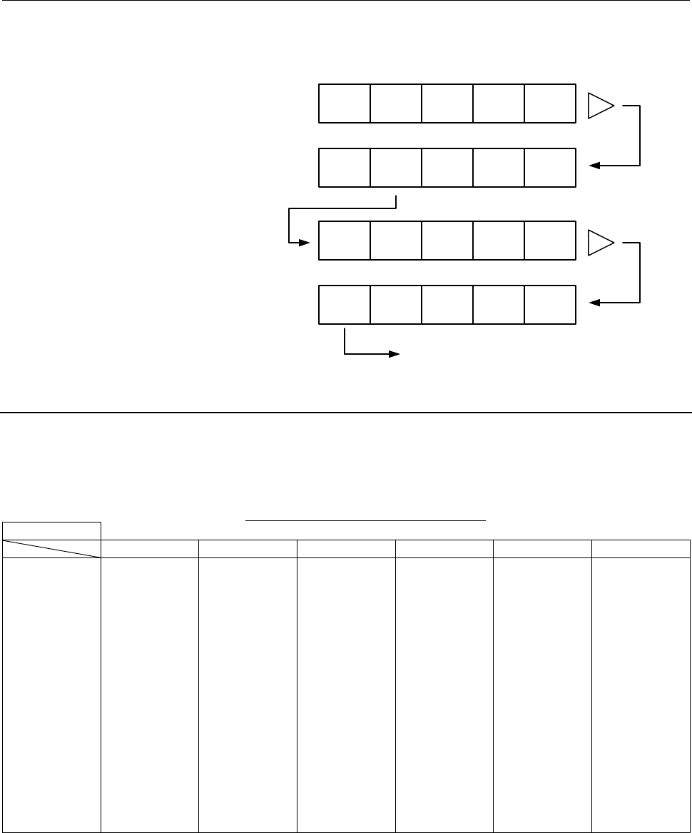
This function creates a table for each of eight specified peak powers.
For one peak power, 8 frequencies and 6 duty cycles can be set.
Frequencies and duty cycles need not be set at equal intervals.
Data table for actual output estimation
Peak power
Duty 1 Duty 2 Duty 3 Duty 4 Duty 5 Duty 6
Frequency 1 Actual output
1
Actual output
9
Actual output
17
Actual output
25
Actual output
33
Actual output
41
Frequency 2 Actual output
2
Actual output
10
Actual output
18
Actual output
26
Actual output
34
Actual output
42
Frequency 3 Actual output
3
Actual output
11
Actual output
19
Actual output
27
Actual output
35
Actual output
43
Frequency 4 Actual output
4
Actual output
12
Actual output
20
Actual output
28
Actual output
36
Actual output
44
Frequency 5 Actual output
5
Actual output
13
Actual output
21
Actual output
29
Actual output
37
Actual output
45
Frequency 6 Actual output
6
Actual output
14
Actual output
22
Actual output
30
Actual output
38
Actual output
46
Frequency 7 Actual output
7
Actual output
15
Actual output
23
Actual output
31
Actual output
39
Actual output
47
Frequency 8 Actual output
8
Actual output
16
Actual output
24
Actual output
32
Actual output
40
Actual output
48
Eight tables are prepared (for peak powers 1 to 8).
Data to be registered needs to satisfy the following conditions:
Peak power 1 < Peak power 2 < Peak power 3 . . < Peak power 8
Frequency 1 < Frequency 2 < Frequency 3 . . . < Frequency 8
Duty 1 < Duty 2 < Duty 3 . . < Duty 6
Contents Summary of LASER C1000/C2000/C4000/C6000-MODEL E Maintenance manual
- Page 1FANUC LASER C1000-MODEL E FANUC LASER C2000-MODEL E FANUC LASER C4000-MODEL E FANUC LASER C5000-MODEL E FANUC LASER C6000-MODEL E For Europe MAINTENANCE MANUAL B-70315EN/02
- Page 2Ȧ No part of this manual may be reproduced in any form. Ȧ All specifications and designs are subject to change without notice. In this manual we have tried as much as possible to describe all the various matters. However, we cannot describe all the matters which must not be done, or which cannot be
- Page 3B-70315EN/02 SAFETY PRECAUTIONS SAFETY PRECAUTIONS This manual contains precautions, which must be observed during operation and maintenance of the laser oscillator to ensure the safety of the operator and maintenance personnel and prevent damage to the oscillator. Maintenance involves a variety of
- Page 4SAFETY PRECAUTIONS B-70315EN/02 1.1 DEFINITION OF WARNING, CAUTION, AND NOTE To ensure the safety of maintenance personnel (referred to as users) and prevent damage to the machine, this manual indicates each precaution on safety with "Warning" or "Caution" according to its severity. Supplementary in
- Page 5B-70315EN/02 SAFETY PRECAUTIONS 1.2 WARNINGS AND CAUTIONS ON EXPOSURE WARNING 1 It is extremely dangerous to expose your eyes to direct, scattered, or reflected CO2 laser light. Always wear protective glasses while the laser is operating. Exposure to laser light can cause blindness. If your eyes are
- Page 6SAFETY PRECAUTIONS B-70315EN/02 WARNING 6 If there is a possibility of being exposed to CO2 laser radiation exceeding the maximum permissible exposure (MPE) level for skin, wear protective clothing. Otherwise, there is a danger of being burnt. 7 The oscillator is fitted with a red semiconductor lase
- Page 7B-70315EN/02 SAFETY PRECAUTIONS 1.3 WARNINGS AND CAUTIONS ON MAINTENANCE WARNING 1 A high voltage of 3 to 4 kV0-p is applied to some places in the laser oscillator cabinet. Therefore, do not turn the power to the oscillator on or operate the oscillator when an oscillator panel is open. Operating the
- Page 8SAFETY PRECAUTIONS B-70315EN/02 1.4 WARNINGS AND CAUTIONS ON HANDLING WARNING 1 The oscillator output mirror and focusing lens on the machining head both have a substrate made of ZnSe (zinc selenide), a toxic substance. Therefore, do not touch the mirror or lens with your bare hands if it is damaged
- Page 9B-70315EN/02 SAFETY PRECAUTIONS CAUTION 1 The oscillator is controlled according to the CNC internal parameter settings. If a numeric value different from a setting is entered and the oscillator is operated, the oscillator may malfunction. In the worst case, the oscillator may be damaged. 2 Use lase
- Page 10SAFETY PRECAUTIONS B-70315EN/02 1.5 WARNINGS AND CAUTIONS ON MACHINING WARNING 1 Do not look at the machining point without eye protection. Otherwise, your eyes may be exposed to reflected laser light, resulting in blindness. If your eyes are accidentally exposed to laser light, seek medical advice
- Page 11B-70315EN/02 PREFACE PREFACE Contents of the manual This manual consists of the following chapters and appendixes: Chapter 1 : Safety for Laser Handling Chapter 1 describes the warning labels affixed to the optical paths in the oscillator, and warnings, cautions and notes on high voltages, high temp
- Page 12PREFACE B-70315EN/02 Applicable models This manual covers the following models. The following abbreviations may be used in the text of this manual. Model Abbreviation FANUC LASER C1000-MODEL E C1000-E FANUC LASER C2000-MODEL E C2000-E FANUC LASER C4000-MODEL E C4000-E FANUC LASER C5000-MODEL E C5000
- Page 13B-70315EN/02 TABLE OF CONTENTS TABLE OF CONTENTS SAFETY PRECAUTIONS............................................................................s-1 PREFACE ....................................................................................................p-1 1 SAFETY FOR LASER HANDLING .............
- Page 14TABLE OF CONTENTS B-70315EN/02 3.2.3.2 Details of safety circuit ...................................................................................... 68 3.2.4 Inter-unit Connections............................................................................................73 3.2.4.1 Vacuum tube co
- Page 15B-70315EN/02 TABLE OF CONTENTS 5.3.3 Power Supply Cannot Be Switched On Using CRT/MDI Switch........................133 5.3.4 Laser Output Just after Switch On Is Low ...........................................................133 5.3.5 Display of Fluctuating Laser Output on CRT .....................
- Page 16TABLE OF CONTENTS B-70315EN/02 7.7.1 Checking the Parameters ......................................................................................181 7.7.2 Replacement Method............................................................................................190 7.8 EXHAUST PUMP ............
- Page 17B-70315EN/02 TABLE OF CONTENTS 7.16.1 Replacing a Fan Unit............................................................................................218 7.16.2 Attaching and Detaching a Cable to and from the Terminal Block .....................218 7.16.3 Replacing a Fan-assisted Radiator...........
- Page 18TABLE OF CONTENTS B-70315EN/02 8.4.2 Procedure..............................................................................................................249 8.5 POWER CALIBRATION METHOD............................................................ 251 8.5.1 Setting a Power Input Compensation Coeffi
- Page 19B-70315EN/02 TABLE OF CONTENTS APPENDIX A EXTERNAL VIEW OF LASER OSCILLATOR .................................... 275 B SPECIFICATIONS............................................................................... 279 C ERROR CODE LIST..................................................................
- Page 20TABLE OF CONTENTS B-70315EN/02 G INSTALLING GAS FITTINGS AND WATER FITTINGS ..................... 348 G.1 GAS FITTINGS.......................................................................................... 349 G.1.1 Tightening a Fittings ...........................................................
- Page 21B-70315EN/02 1.SAFETY FOR LASER HANDLING 1 SAFETY FOR LASER HANDLING C1000-E, C2000-E, C4000-E, C5000-E and C6000-E produce the rated output laser power of 1000W, 2000W, 4000W, 5000W and 6000W. The CO2 laser beam is the wavelength of 10.6 µm, far infrared, and is invisible to human eyes. The adequat
- Page 221.SAFETY FOR LASER HANDLING B-70315EN/02 1.1 LASER BEAM Fig.1.1(a)-(j) show the position of panel that laser beam exposure is occurred without panel. 1) Potential hazards Laser oscillator emits CO2 laser beam(10.6 µm), which is high power and invisible. • Being directly exposed to the CO2 beam could
- Page 23B-70315EN/02 1.SAFETY FOR LASER HANDLING Fig.1.1(a) Laser beam exposure is occurred without panel as operating. (C1000-E) Fig.1.1(b) Laser beam exposure is occurred without panel as operating (C2000-E) Fig.1.1(c) Laser beam exposure is occurred without panel as operating (C4000-E) -3-
- Page 241.SAFETY FOR LASER HANDLING B-70315EN/02 Fig.1.1(d) Laser beam exposure is occurred without panel as operating (C5000-E) Fig.1.1(e) Laser beam exposure is occurred without panel as operating (C6000-E) -4-
- Page 25B-70315EN/02 1.SAFETY FOR LASER HANDLING Fig.1.1(f) The position of laser beam delivery (C1000-E) -5-
- Page 261.SAFETY FOR LASER HANDLING B-70315EN/02 Fig.1.1(g) The position of laser beam delivery (C2000-E) Fig.1.1(h) The position of laser beam delivery (C4000-E) -6-
- Page 27B-70315EN/02 1.SAFETY FOR LASER HANDLING Fig.1.1(i) The position of laser beam delivery (C5000-E) Fig.1.1(j) The position of laser beam delivery (C6000-E) -7-
- Page 281.SAFETY FOR LASER HANDLING B-70315EN/02 1.2 HIGH VOLTAGE Fig.1.2(a)-(j) show the position of high voltage in oscillator. 1) Potential hazards There is RF voltage of 3 to 4kVo-p in the cabinet of the laser oscillator. There is 200 VAC power in the relay panel, be careful not to touch the high voltag
- Page 29B-70315EN/02 1.SAFETY FOR LASER HANDLING Fig.1.2(a) The position of high voltage in C1000-E (Front, maintenance side). Fig.1.2(b) The position of high voltage in C1000-E (Back side). -9-
- Page 301.SAFETY FOR LASER HANDLING B-70315EN/02 Fig.1.2(c) The position of high voltage in C2000-E (Front, maintenance side). Fig.1.2(d) The position of high voltage in C2000-E (Back side). - 10 -
- Page 31B-70315EN/02 1.SAFETY FOR LASER HANDLING Fig.1.2(e) The position of high voltage in C4000-E (Front, maintenance side). Fig.1.2(f) The position of high voltage in C4000-E (Back side). - 11 -
- Page 321.SAFETY FOR LASER HANDLING B-70315EN/02 Fig.1.2(g) The position of high voltage in C5000-E (Front, maintenance side). Fig.1.2(h)The position of high voltage in C5000-E (Back side). - 12 -
- Page 33B-70315EN/02 1.SAFETY FOR LASER HANDLING Fig.1.2(i) The position of high voltage in C6000-E (Front, maintenance side). Fig.1.2(j) The position of high voltage in C6000-E (Back side). - 13 -
- Page 341.SAFETY FOR LASER HANDLING B-70315EN/02 1.3 SAFETY ENCLOSURE (AT YOUR WORK STATION) 1) Potential hazards CO2 beam is delivery from oscillator. Direct or scattered beam is exposed. 2) Safety recommendations Mount the safety enclosure made of acrylic resin which can absorb the laser beam around the w
- Page 35B-70315EN/02 1.SAFETY FOR LASER HANDLING 1.6 HIGH TEMPERATURE Fig.1.6(a)-(j) show the position of high voltage in oscillator. 1) Potential hazards When you touch a part of high temperature, your skin burn. 2) Safety recommendations The pipes of the gas circular system are very a high temperature. Do
- Page 361.SAFETY FOR LASER HANDLING B-70315EN/02 Fig.1.6(a) The position of high temperature in C1000-E (Front, maintenance side). Fig.1.6(b) The position of high temperature in C1000-E (Back side). - 16 -
- Page 37B-70315EN/02 1.SAFETY FOR LASER HANDLING Fig.1.6(c) The position of high temperature in C2000-E (Front, maintenance side). Fig.1.6(d) The position of high temperature in C2000-E (Back side). - 17 -
- Page 381.SAFETY FOR LASER HANDLING B-70315EN/02 Fig.1.6(e) The position of high temperature in C4000-E (Front, maintenance side). Fig.1.6(f) The position of high temperature in C4000-E (Back side). - 18 -
- Page 39B-70315EN/02 1.SAFETY FOR LASER HANDLING Fig.1.6(g) The position of high temperature in C5000-E (Front, maintenance side). Fig.1.6(h) The position of high temperature in C5000-E (Back side). - 19 -
- Page 401.SAFETY FOR LASER HANDLING B-70315EN/02 Fig.1.6(i) The position of high temperature in C6000-E (Front, maintenance side). Fig.1.6(j) The position of high temperature in C6000-E (Back side). - 20 -
- Page 41B-70315EN/02 1.SAFETY FOR LASER HANDLING 1.7 WARNING LABELS The oscillator uses high voltages and laser beam radiation. Such hazards are indicated with warning labels attached to the positions shown in Fig. 1.7(a) to (j). This section describes the warning labels and their positions. Fig.1.7(a) Warn
- Page 421.SAFETY FOR LASER HANDLING B-70315EN/02 Fig.1.7(c) Warning label positions (C2000-E : front view) Fig.1.7(d) Warning label positions (C2000-E : back view) - 22 -
- Page 43B-70315EN/02 1.SAFETY FOR LASER HANDLING Fig.1.7(e) Warning label positions (C4000-E : front view) Fig.1.7(f) Warning label positions (C4000-E : back view) - 23 -
- Page 441.SAFETY FOR LASER HANDLING B-70315EN/02 Fig.1.7(g) Warning label positions (C5000-E : front view) Fig.1.7(h) Warning label positions (C5000-E : back view) - 24 -
- Page 45B-70315EN/02 1.SAFETY FOR LASER HANDLING Fig.1.7(i) Warning label positions (C6000-E : front view) Fig.1.7(j) Warning label positions (C6000-E : back view) - 25 -
- Page 461.SAFETY FOR LASER HANDLING B-70315EN/02 <1> Class indication label (C1000-E) <1> Class indication label (C2000-E,C4000-E,C5000-E,C6000-E) - 26 -
- Page 47B-70315EN/02 1.SAFETY FOR LASER HANDLING <2> Warning logotype <3> Access label <4> Label inside the access panel <5> Lifting method label - 27 -
- Page 481.SAFETY FOR LASER HANDLING B-70315EN/02 <6> Aperture label <7> Label of non-interlocked protective panel <8> Identification label - 28 -
- Page 49B-70315EN/02 1.SAFETY FOR LASER HANDLING <9> Address label <10> Discharge section label <11> Supply voltage label <12> Label of over-current protective - 29 -
- Page 501.SAFETY FOR LASER HANDLING B-70315EN/02 <13> Label of motor and transformer (C1000-E) <13> Label of motor and transformer (C2000-E) <13> Label of motor and transformer (C4000-E) - 30 -
- Page 51B-70315EN/02 1.SAFETY FOR LASER HANDLING <13> Label of motor and transformer (C5000-E,C6000-E) <14> Label of warning light <15> Maintenance label <16> Certification label - 31 -
- Page 521.SAFETY FOR LASER HANDLING B-70315EN/02 <17> Short-circuit interrupting capacity of main breaker (C1000-E) <17> Short-circuit interrupting capacity of main breaker (C2000-E, C4000-E) <17> Short-circuit interrupting capacity of main breaker (C5000-E) <17> Short-circuit interrupting capacity of main
- Page 53B-70315EN/02 1.SAFETY FOR LASER HANDLING <18> Label for regulating the atmospheric gases in the oscillator housing <19> Cooling water and gas maintenance label - 33 -
- Page 541.SAFETY FOR LASER HANDLING B-70315EN/02 1.8 HIGH-PRESSURE GAS Do not allow any dangerous or high-pressure gas to get into the oscillator housing. The oscillator cabinet has a hermetic structure (dustproof and drip-proof), it cannot be ventilated easily. Flammable gases such as oxygen can cause a fi
- Page 55B-70315EN/02 1.SAFETY FOR LASER HANDLING 1.10 SHUTTER LOCK The shutter lock is prepared because it dose not put out the laser beam by mistake. If you do not put out the beam, lock the shutter. Use the mechanical switch at shutter lock switch, not electrical component (Relay)or switching circuit (Tra
- Page 562.INTERNAL STRUCTURE B-70315EN/02 2 INTERNAL STRUCTURE - 36 -
- Page 57B-70315EN/02 2.INTERNAL STRUCTURE 2.1 OUTLINE Fig. 2.1 shows an outline of the structure of the oscillator. Fig.2.1 Outline of structure (1) Laser resonator The resonator consists of an output coupler, a rear mirror, folding mirrors, discharge tubes, a power sensor unit, etc. Several discharge tubes
- Page 582.INTERNAL STRUCTURE B-70315EN/02 (3) Laser gas circulating system A gas circulating system is configured by connecting the resonator and the fan (turbo blower) with a circulating pipe. Laser gas runs through the discharge tubes at a speed of 200 m/s or higher. In this circulating system, a water-co
- Page 59B-70315EN/02 2.INTERNAL STRUCTURE 2.2 INTERNAL STRUCTURE This section describes the internal structure of the oscillator more specifically. Fig.2.2(a) to (j) are internal structural drawing. Fig.2.2(a) Internal structural drawing (C1000-E : front view) Fig.2.2(b) Internal structural drawing (C1000-E
- Page 602.INTERNAL STRUCTURE B-70315EN/02 Fig.2.2(c) Internal structural drawing (C2000-E : front view) Fig.2.2(d) Internal structural drawing (C2000-E : rear view) - 40 -
- Page 61B-70315EN/02 2.INTERNAL STRUCTURE Fig.2.2(e) Internal structural drawing (C4000-E : front view) Fig.2.2(f) Internal structural drawing (C4000-E : rear view) - 41 -
- Page 622.INTERNAL STRUCTURE B-70315EN/02 Fig.2.2(g) Internal structural drawing (C5000-E : front view) Fig.2.2(h) Internal structural drawing (C5000-E : rear view) - 42 -
- Page 63B-70315EN/02 2.INTERNAL STRUCTURE Fig.2.2(i) Internal structural drawing (C6000-E : front view) Fig.2.2(j) Internal structural drawing (C6000-E : rear view) - 43 -
- Page 642.INTERNAL STRUCTURE B-70315EN/02 (1) Output coupler A transmitting/reflecting mirror, which outputs the laser beam after it, has been amplified inside the resonator. The output coupler consists of a ZnSe (zinc selenide) substrate with a curvature on the surface and coated with dielectric. ZnSe is h
- Page 65B-70315EN/02 2.INTERNAL STRUCTURE (9) Matching box The matching box contains a matching circuit, which ensures that power is effectively input to the discharge tubes. (10) Turbo blower This fan circulates the laser gas in the gas circulating system at high speed. It rotates at a high speed of 60,000
- Page 662.INTERNAL STRUCTURE B-70315EN/02 (18) Exhaust control unit (C2000-E, C4000-E) The exhaust control unit is capable of controlling the flow rate of the gas to be exhausted. (19) Exhaust pump This pump is used to vacuum-exhaust laser gas from the gas circulating system such that its pressure falls to
- Page 67B-70315EN/02 2.INTERNAL STRUCTURE (27) Interface PCB This PCB communicates with the CNC via the FANUC I/O LINK (serial interface). (28) Stabilized power supply This unit supplies DC power (24 VDC) to the interface PCB and various units. (29) Dew sensor This sensor is mounted to the output coupler ho
- Page 683.INSTALLATION B-70315EN/02 3 INSTALLATION - 48 -
- Page 69B-70315EN/02 3.INSTALLATION 3.1 INSTALLATION PROCEDURE Use the following procedure to make adjustments and checks during installation. As soon as the oscillator is delivered, loosen the clamps of the resonator described in (2) below. CAUTION If the clamps of the resonator are left fastened for a lon
- Page 703.INSTALLATION B-70315EN/02 Fig.3.1(b) Clamp locations (C2000-E) Fig.3.1(c) Clamp locations (C4000-E) - 50 -
- Page 71B-70315EN/02 3.INSTALLATION Fig.3.1(d) Clamp locations (C5000-E) Fig.3.1(e) Clamp locations (C6000-E) - 51 -
- Page 723.INSTALLATION B-70315EN/02 Mirror holder Safety cover Shutter unit Space <2> between beam flange and beam cover pipe Bolt <1> Beam Beam cover pipe Flange Beam cover pipe Fig.3.1(f) Safety cover for shutter unit Fig.3.1(g) The details of Safety cover (3) Check the safety cover of shutter unit The be
- Page 73B-70315EN/02 3.INSTALLATION (4) Check the outsides of units installed in the oscillator as follows: Check items 1 Check whether any printed circuit boards are loose or removed. Check whether any cables are damaged (such as damaged 2 sheathing). 3 Check whether any connectors are loose or detached. 4
- Page 743.INSTALLATION B-70315EN/02 (9) Check the supply gas pressure. Check that the secondary pressure of the gas regulator is 0.175±0.025 MPa. (10) Turn on the power, then check the operation of the fan motors in the housing. The fan motors installed in the oscillator start turning as soon as the power t
- Page 75B-70315EN/02 3.INSTALLATION (13) Conduct an oscillator vacuum leakage test. Check the oscillator for any internal leakage. When performing the leakage check, use the automatic leakage check function described in Subsection 3.3.4. If there is internal leakage, locate the leakage according to the leak
- Page 763.INSTALLATION B-70315EN/02 3.2 OSCILLATOR CONNECTIONS The oscillator has connections for laser gas piping, cooling water piping, and power and signal cables. For details of the electrical connections for the CNC and machine, refer to the corresponding connection manual. 3.2.1 Laser Gas 3.2.1.1 Lase
- Page 77B-70315EN/02 3.INSTALLATION 3.2.1.3 Leakage in external piping After installing the piping, see Subsection 3.3.2, and be sure to conduct a clamp test to check for gas leakage. If the rate of change in primary pressure over eight hours exceeds 5%, or if the rate of change in secondary pressure over e
- Page 783.INSTALLATION B-70315EN/02 3.2.2 Cooling Water 3.2.2.1 Specification of the cooling water The quality of cooling water is specified in the table below. Use pure water or tap water passed through an ion exchanger. pH (25°C) 6.0 to 8.0 Conductivity (25°C) 200µS/cm or less Standard Chlorine ion Cl- 20
- Page 79B-70315EN/02 3.INSTALLATION 3.2.2.4 Anticorrosive Add the following anticorrosive to cooling water immediately after installation to prevent problems due to corroding cooling water and to decrease the frequency of replacement of cooling water. Consult the chiller manufacturer for use of the anticorr
- Page 803.INSTALLATION B-70315EN/02 3.2.2.6 Antifreezing solution If the chiller is used in a cold district, it should be provided with an antifreezing function. When the air temperature falls, the water supply pump should be kept running. In a very cold district, incorporate a heater into the chiller to pr
- Page 81B-70315EN/02 3.INSTALLATION 3.2.3 Electrical Connections 3.2.3.1 NC-to-oscillator connection and power supply cable connection Connect the cables to the laser oscillator as described below. (1) Power cable U (R), V (S), W (T) Recommended power cables (a) If placing the cable in the duct If laying th
- Page 823.INSTALLATION B-70315EN/02 (b) If not placing the cable in the duct If not placing the power cable in the duct between the power board and the laser oscillator, you can use a heavy-duty power cord cable. OSC Recommendation Cross Section Diameter Current Type Layout C1000-E 2 4 Core Hitachi Cable :
- Page 83B-70315EN/02 3.INSTALLATION (e) Tightening torque for terminal Tightening torque of mounting screws is as follows. OSC Torque C1000-E 5.5 to 7.5N⋅m C2000-E 15N⋅m C4000-E 15N⋅m C5000-E 8 to 13N⋅m C6000-E 10 to 15N⋅m (2) Ground cable There are two grounding locations. One of the locations is for calss
- Page 843.INSTALLATION B-70315EN/02 Fig.3.2.3.1(a) Cable connection (C1000-E) Fig.3.2.3.1(b) Cable connection of (C2000-E) - 64 -
- Page 85B-70315EN/02 3.INSTALLATION Fig.3.2.3.1(c) Cable connection (C4000-E) Fig.3.2.3.1(d) Cable connection (C5000-E) - 65 -
- Page 863.INSTALLATION B-70315EN/02 Fig.3.2.3.1(e) Cable connection (C6000-E) Fig.3.2.3.1(f) Location and Signal assignment of CNL1 L1 L2 L3 Power cable terminal Fig.3.2.3.1(g) Power cable terminal of C6000-E - 66 -
- Page 87B-70315EN/02 3.INSTALLATION 4) CNL1 terminal B8 PF2 A8 PF1 B7 OFI2 A7 OFI1 B6 A2 A6 A1 B5 EMS2 A5 EMS1 B4 RUN2 A4 RUN1 B3 SHL2 A3 SHL B2 A2 SC B1 IB2 A1 IB1 CNL1 pin arrangement (as viewed from the wiring surface) a) PF1 and PF2 These terminals are for QF1 voltage tripping. Connect +24 VDC and 0 V t
- Page 883.INSTALLATION B-70315EN/02 3.2.3.2 Details of safety circuit The figure shows the safety circuit for each oscillator. Fig.3.2.3.2(a) Safety circuit of C1000-E - 68 -
- Page 89B-70315EN/02 3.INSTALLATION Fig.3.2.3.2(b) Safety circuit of C2000-E - 69 -
- Page 903.INSTALLATION B-70315EN/02 Fig.3.2.3.2(c) Safety circuit of C4000-E - 70 -
- Page 91B-70315EN/02 3.INSTALLATION Fig.3.2.3.2(d) Safety circuit of C5000-E - 71 -
- Page 923.INSTALLATION B-70315EN/02 Fig.3.2.3.2(e) Safety circuit of C6000-E - 72 -
- Page 93B-70315EN/02 3.INSTALLATION 3.2.4 Inter-unit Connections The C1000-E has an oscillator section and exhaust pump section. Inter-unit connections include 1. vacuum tube connection and 2. power cable connection. Before making connections, check the following: (a) Check for any foreign particles in comp
- Page 943.INSTALLATION B-70315EN/02 3.2.4.1 Vacuum tube connection Prepare the following parts: • Pt screwed pipe fittings (elbow) : (included in the fittings kit (A04B-0816-K354)) • Tube : (included in the connection kit (A04B-0816-K130)) • Union : (included in the fittings kit (A04B-0816-K354)) • Adapter
- Page 95B-70315EN/02 3.INSTALLATION 3.3 DETAILS OF CHECKING 3.3.1 Power Supply Checking 3.3.1.1 Checking the power supply Check whether the power supply satisfies the following specifications: 200VAC +10%, -15%, 50/60Hz ±1Hz, 3φ or 220VAC +10%, -15%, 60Hz±1Hz, 3φ 3.3.1.2 Phase rotation Connect input termina
- Page 963.INSTALLATION B-70315EN/02 Fig.3.3.1.4(a) IF PC board (2) Stabilized power supply unit : See Fig.3.3.1.4(b). This unit supplies +24 V to the IF PC board. Specification : A20B-1005-0124 Fuse : FU :A60L-0001-0175#3.2 3.2A (2 pieces are used.) Fuse Fig.3.3.1.4(b) Stabilized power supply - 76 -
- Page 97B-70315EN/02 3.INSTALLATION 3.3.1.5 Checking the jumper pins Jumper pin Setting Enables communication with the CNC via a JD1 metal cable (When connector JD1B is used for connection) LINK1 Enables communication with the CNC via an COP optical fiber cable (When connector COP1B is used for connection)
- Page 983.INSTALLATION B-70315EN/02 3.3.2 External Laser Gas Piping Leakage Check (Clamp Test) When you have installed or modified laser gas piping, conduct a clamp test that checks for any leakage by sealing laser gas inside the piping and observing the pressure change after a specified period of time. (1)
- Page 99B-70315EN/02 3.INSTALLATION 3.3.3 Checking Cooling Water (1) Turn off the main circuit breaker of the oscillator and the power supply. (2) Check that the water piping is connected to the water inlet (IN) and outlet (OUT) of the oscillator in the correct direction. (3) Completely open the water pipin
- Page 1003.INSTALLATION B-70315EN/02 3.3.4 Check for Leakage within the Oscillator (1) Using the automatic leakage check function Usually, use this method to check for leakage. For how to conduct this check see Section 9.3. (2) Manual check method To investigate the leakage status in detail, follow the proce
- Page 101B-70315EN/02 3.INSTALLATION 3.3.5 Locating Internal Leakage When gas leakage is present inside the oscillator, use a helium leakage detector or liquid leakage checker to locate the leakage. CAUTION Because the turbo blower is not designed to withstand pressure increase, do not increase pressure beyo
- Page 1023.INSTALLATION B-70315EN/02 3.3.6 Discharge Aging If the oscillator is left unused for a long time (three days or more), or if the laser gas circulating system has been opened to the atmosphere (for example, to clean the mirrors or replace gas system components), aging is required. This involves war
- Page 103B-70315EN/02 3.INSTALLATION 3.3.7 Oscillation Characteristics (1) Modify the parameters listed below. PRM No.15000.4bit 1 (enables power correction) (2) Turn on the oscillator start switch to place the oscillator in the discharge state. (3) When the oscillator starts discharge, power correction is p
- Page 1043.INSTALLATION B-70315EN/02 3.3.9 Power Supply Margin Check (Pulse Check) (1) Modify the parameters listed below. PRM No.15000.2bit 1 (Use of assist gas is disabled at beam-on.) PRM No.15000.3bit 1 (Internal discharge is enabled in manual mode.) PRM.No.15008.6bit 0 (Automatic aging is disabled.) PRM
- Page 105B-70315EN/02 3.INSTALLATION 3.3.10 Beam Mode Check CAUTION A beam mode deviation may occur depending on the transportation method and storage condition. When installing the oscillator, be sure to perform this step. A mode deviation does not mean a failure. Perform alignment by following the procedur
- Page 1063.INSTALLATION B-70315EN/02 (5) Set the conditions of the beam output program as follows: Output = Rated output Duty = 100 % Duration = See the following table. Perform internal discharge with a rated output specified. If actual output Pa differs from the specified output, mode shape comparison beco
- Page 107B-70315EN/02 3.INSTALLATION 3.4 PREPARATION PRIOR TO SHIPMENT For shipment and transportation, follow the steps explained below. (1) Disconnect all CNC connecting cables. (2) Disconnect the power cable and ground cable. Cover the cable inlet holes with tape or the like. (3) Remove the laser gas pipe
- Page 1083.INSTALLATION B-70315EN/02 3.4.1 Packing for Transportation Prior to shipment and transportation, the packing and checking operations described below must be performed. (1) External dimensions : See the Appendix A. (2) Weight of product : Model Weight C1000-E Approx. 350kg + Approx. 30kg (Exhaust p
- Page 109B-70315EN/02 3.INSTALLATION 3.4.2 Removing Cooling Water Remove cooling water according to the procedure below. (1) Open the cooling water inlet (IN) and outlet (OUT), and leave both open. (2) Once the cooling water has stopped draining, connect a compressed air hose to the cooling water inlet (IN).
- Page 1104.MAINTENANCE B-70315EN/02 4 MAINTENANCE In FANUC LASER C1000/C2000/C4000/C5000/C6000-MODEL E, periodic inspection items have been reduced, and adjustments have been made easy. To keep the oscillator in a satisfactory operating condition over a long period, however, it is necessary to carry out peri
- Page 111B-70315EN/02 4.MAINTENANCE 4.1 DAILY INSPECTION Table 4.1 lists daily inspection items. Inspect the FANUC LASER C1000/C2000/C4000/C5000/C6000-MODEL E according to this table. When parts (including oil) have been used for a prescribed period, replace them quickly. Table 4.1 Daily inspection items for
- Page 1124.MAINTENANCE B-70315EN/02 4.2 PERIODIC MAINTENANCE The laser oscillator contains consumables that must be replaced periodically. Table 4.2(a) or (b) lists such consumables and the related periodic maintenance work. Perform periodic maintenance as well as daily inspection described in Section 4.1 by
- Page 113B-70315EN/02 4.MAINTENANCE 4.3 DETAILS OF MAINTENANCE When opening the panels and doors during maintenance, keep the power turned off. Before replacing oil, be sure to check that purging is completed. Fig.4.3(a) Oil gauge of turbo blower and exhaust pump (C1000-E) A B Fig.4.3(b) Oil gauge of turbo b
- Page 1144.MAINTENANCE B-70315EN/02 A B Fig.4.3(c) Oil gauge of turbo blower and exhaust pump (C4000-E) B A A Fig.4.3(d) Oil gauge of turbo blower and exhaust pump (C5000-E) - 94 -
- Page 115B-70315EN/02 4.MAINTENANCE A A B Fig.4.3(e) Oil gauge of turbo blower and exhaust pump (C6000-E) - 95 -
- Page 1164.MAINTENANCE B-70315EN/02 4.3.1 Turbo Blower Oil (1) Check method Check the amount of oil in the turbo blower while referring to the figure below. The oil level should be between graduations H and L. This check should be made when the oscillator is at a rest. When the turbo blower is running, it is
- Page 117B-70315EN/02 4.MAINTENANCE NOTE Execute discharge aging after changing turbo blower oil. Fig.4.3.1 Turbo blower oil check points NOTE 1 Use turbo blower oil within an expiratio date. 2 If the container is opened, use the oil in that within 6 months. 3 Use a clean supply tube when you pour the oil an
- Page 1184.MAINTENANCE B-70315EN/02 4.3.2 Exhaust Pump Oil (1) Check method Watch the oil gauge, and check that the oil level is between graduations L and H. Also check whether the oil is dark. If the oil level is below L, add oil to the turbo blower or replace the oil in it. If the oil level is above H, dra
- Page 119B-70315EN/02 4.MAINTENANCE 4.3.3 Exhaust Pump Filter (1) Replacement method Replace the filter every 3000 hours, or when the exhaust power has degraded. If the filter gets clogged, the pump output becomes low. Fig. 4.3.3 shows where the filter of a exhaust pump is located. 1) Stop the oscillator, an
- Page 1204.MAINTENANCE B-70315EN/02 4.4 MAINTENANCE PARTS The maintenance parts are listed below. Refer to the following tables for maintenance unit and parts specification information. CONSUMABLES Quantity No. Item Specifications C1000-E C2000-E C4000-E C5000-E C6000-E 1 Output coupler A98L-0003-0045 1 0 0
- Page 121B-70315EN/02 4.MAINTENANCE Quantity No. Item Specifications C1000-E C2000-E C4000-E C5000-E C6000-E Temperature switch 43 A57L-0001-0095/B080 0 0 1 1 1 for absorber Temperature switch 44 A57L-0001-0095/B090 0 0 0 1 1 for absorber Temperature switch 45 A57L-0001-0057/080 0 1 0 0 0 for shutter mirror
- Page 1224.MAINTENANCE B-70315EN/02 Quantity No. Item Specifications C1000-E C2000-E C4000-E C5000-E C6000-E 1 1 1 76 Breaker A60L-0001-0391/V030 0 0 QF3 QF4 QF6 1 2 2 77 Breaker A60L-0001-0308/X010 0 0 QF4 QF5,6 QF7,8 1 78 Breaker A60L-0001-0308/V005 0 0 0 0 QF5 5 7 79 Breaker A60L-0001-0423/Q050 0 0 0 QF2-
- Page 123B-70315EN/02 4.MAINTENANCE Quantity No. Item Specifications C1000-E C2000-E C4000-E C5000-E C6000-E 110 Photo catalytic element A290-4514-V170 2 0 0 0 0 111 Photo catalytic element A290-4523-V170 0 2 0 0 0 112 Photo catalytic element A290-4540-V170 0 0 2 2 0 113 Photo catalytic element A290-4562-V17
- Page 1244.MAINTENANCE B-70315EN/02 REPAIRABLE PARTS Quantity No. Item Specifications C1000-E C2000-E C4000-E C5000-E C6000-E 1 Laser PSU unit A14B-0082-B209 (1) (2) (4) 0 0 2 Laser PSU unit A14B-0082-B211 1 2 4 4 6 3 Matching box A14B-0082-B316 1 0 0 0 0 4 Matching box A14B-0082-B311 0 2 0 0 0 5 Matching bo
- Page 125B-70315EN/02 4.MAINTENANCE Quantity No. Item Specifications C1000-E C2000-E C4000-E C5000-E C6000-E 51 Water distributor A04B-0813-C420 0 1 0 0 0 52 Water distributor A04B-0815-C420 0 0 1 0 0 53 Water distributor A04B-0817-C421 0 0 0 1 0 54 Water distributor A A290-4562-V800 0 0 0 0 1 55 Water distr
- Page 1265.TROUBLESHOOTING B-70315EN/02 5 TROUBLESHOOTING - 106 -
- Page 127B-70315EN/02 5.TROUBLESHOOTING 5.1 TROUBLESHOOTING PROCEDURE The troubleshooting procedure to be applied depends on the failure occurrence status as indicated below. Perform checking according to the items listed below. (1) Action in response to alarm screen display (See Section 5.2.) (2) Major faul
- Page 1285.TROUBLESHOOTING B-70315EN/02 5.2 RESPONDING TO ALARM MESSAGES ON THE SCREEN Alarm numbers, as well as DGN and PRM Nos., are those of the FS16i-L. See the conceptual diagram of alarm processing and a list of alarms in an appendix of this manual. ALM No.4061 A/D CONVERTER–1 Alarm output condition Th
- Page 129B-70315EN/02 5.TROUBLESHOOTING ALM No.4063 RF POWER SUPPLY / LASER GAS This message appears when the laser power supply unit becomes abnormal or performs protective operation. The power supply unit performs protective operation even if an error occurs in other than the power supply unit itself. This
- Page 1305.TROUBLESHOOTING B-70315EN/02 No. Check item Cause of trouble, Solution 6 Checking the 1) Check whether the laser gas composition is laser gas correct, and replace the laser gas with the one that satisfies the specifications. 2) Check for gas leakage in the external laser gas piping, investigate th
- Page 131B-70315EN/02 5.TROUBLESHOOTING No. Phenomenon Presumption cause 6 The RF voltage of all the units is high and Internal leakage of the laser power is low. The discharge is oscillator tends to disappear. (DCI alarm) Internal leakage of Even though the purge is repeatedly water of the oscillator perfor
- Page 1325.TROUBLESHOOTING B-70315EN/02 See the following table, and check the operation status. [Open] command [Close] command DGN No.973 #0=1 DGN No.973 #0=0 Shutter open state signal 1 1 0 0 1 1 0 0 DGN No.961 #4 Shutter close state signal 0 1 0 1 0 1 0 1 DGN No.961 #5 Normal/Abnormal O X X X X X X O No.
- Page 133B-70315EN/02 5.TROUBLESHOOTING No. Cause of trouble Solution 4 Leakage in vacuum Locate the leakage, and replace the system or water defective part. leakage 5 The gas flow control Adjust the gas flow control valve to obtain valve is closed the specified gas flow rate. 6 Matching box Replace the matc
- Page 1345.TROUBLESHOOTING B-70315EN/02 Alarm output condition This alarm is issued when the actual laser output is in one of the following conditions at the time of beam output: (1) The actual laser output is higher than the average command power (power × duty) by more than the value set in parameter No. 15
- Page 135B-70315EN/02 5.TROUBLESHOOTING No. Cause of trouble Solution 3 Anomaly of power unit of IF See Subsection 3.3.1.4 for details of the PCB (A16B-2100-0142) normal supply voltage. If the allowable voltage range is exceeded, replace the IF PCB. 4 Laser oscillator main circuit Check whether the main circ
- Page 1365.TROUBLESHOOTING B-70315EN/02 No. Cause of trouble Solution 2 Poor connection Check the connection between the assist gas supply unit and CNC. ALM No.4072 CHILL FLOW This alarm appears when the water shortage takes place. Alarm output condition This alarm is issued if the cooling water amount signa
- Page 137B-70315EN/02 5.TROUBLESHOOTING No. Cause of trouble Solution 1 Tool low supply Adjust the secondary pressure at the regulator on pressure of laser the gas cylinder so that the pressure of laser gas gas supplied to the laser oscillator is 0.175MPa±0.025MPa (rating) as measured at the entry of the osc
- Page 1385.TROUBLESHOOTING B-70315EN/02 ALM No.4076 LASER POWER DOWN This alarm is issued if the monitored laser output is lower than the specified laser output by at least the allowable value. Alarm output condition This alarm is issued when the actual laser output level is lower than the average command po
- Page 139B-70315EN/02 5.TROUBLESHOOTING ALM No.4077 ABSORBER TEMP. This alarm is issued if the temperature absorber exceeds the allowable value. In the usual operation, this beam absorber is irradiated by the rated output only during the laser output compensation conducted after the start of the oscillator.
- Page 1405.TROUBLESHOOTING B-70315EN/02 No. Cause of trouble Solution 1 Anomaly of parameter Check whether the values of PRM NO. setting of gas pressure 15000/bit1,15244,15245,15246 are set as control indicated in the attached parameter table. If a different value is set, set the value specified in the data
- Page 141B-70315EN/02 5.TROUBLESHOOTING Alarm output condition Turning the oscillator start switch on causes exhaust to start. This alarm is issued if the laser gas pressure does not reach the setting of parameter No. 15240 when the time set in parameter No.15259 has elapsed. Related parameters PRM.15240 Eva
- Page 1425.TROUBLESHOOTING B-70315EN/02 No. Cause of trouble Solution 5 Anomaly of exhaust If the above checks do not reveal any pump abnormality, the performance of the exhaust pump has deteriorated. Check the following items. 1) Check whether specified oil is provided at an appropriate level. Supply specif
- Page 143B-70315EN/02 5.TROUBLESHOOTING No. Cause of trouble Solution 3 Anomaly of supply laser Adjust the secondary pressure at the gas pressure regulator on the gas cylinder so that the pressure of laser gas supplied to the laser oscillator is 0.175MPa±0.025MPa (rating) as measured at the entry of the osci
- Page 1445.TROUBLESHOOTING B-70315EN/02 Alarm output condition This alarm is issued when the power compensation coefficient exceeds the power compensation limit during execution of power compensation. Power compensation coefficient = (Pc/Pa) × 1024 Pc : Parameter No. 15200 or 15201 Pa : Actual laser output R
- Page 145B-70315EN/02 5.TROUBLESHOOTING ALM No.4088 LASER VOLTAGE DOWN This alarm is issued, if the voltage applied to the discharge tube drops largely. Alarm output condition 1) Immediately before the oscillation ready state (LSTR) is established, the RF voltage of the power supply with the smallest number
- Page 1465.TROUBLESHOOTING B-70315EN/02 ALM No.4090 LASER NOT GENERATE This alarm is issued if an attempt is made to radiate a laser beam when the laser is not in the oscillation ready (LSTR) state. Alarm output condition This alarm is issued if the oscillation ready (LSTR) state is not established during be
- Page 147B-70315EN/02 5.TROUBLESHOOTING Alarm output condition When the integral value of gas pressure control is preset and the pressure is increased from the from the gas pressure at the start of discharge to the gas pressure during oscillation, this alarm is issued if the actual gas pressure has not incre
- Page 1485.TROUBLESHOOTING B-70315EN/02 No. Cause of trouble Solution 1 Invalid parameter Check whether the values of PRM Nos. 15240, setting 15241, and 15242 are set as indicated in the attached parameter table. If a different value is set, set the value specified in the data sheets. 2 Anomaly of turbo Repl
- Page 149B-70315EN/02 5.TROUBLESHOOTING ALM No.4105 TURBO TEMP. 1 This alarm is issued, if the temperature of the turbo blower motor winding becomes higher than the permissible level. Alarm output condition This alarm is issued if the turbo temperature signal becomes "0" after the start of the oscillator and
- Page 1505.TROUBLESHOOTING B-70315EN/02 No. Cause of Solution trouble 4 Insufficient turbo When the temperature of the turbo blower motor blower cooling section is high, check whether the cooling water path is clogged. This alarm is issued also when the cooling water in the turbo blower becomes insufficient.
- Page 151B-70315EN/02 5.TROUBLESHOOTING ALM No.4124 OVER COOL The oscillator has a low temperature sensor on the side of resonator plate to measure the temperature of cooling water. Alarm output condition This alarm is issued if the cooling water temperature becomes less than 20℃ after laser warm-up driving.
- Page 1525.TROUBLESHOOTING B-70315EN/02 5.3 MAJOR FAULTS 5.3.1 Laser Power Supply Alarm Display (1) If an alarm is issued to indicate the occurrence of a power supply fault, check the diagnosis screen to determine which power supply unit issued that alarm signal. The bit corresponding to the power supply uni
- Page 153B-70315EN/02 5.TROUBLESHOOTING Type of Upper Condition Causes alarm limit This alarm is issued if a high RF current flows through the discharge Abnormal RFI 5.45A tube when the oscillator is operating in feedback circuit CW/pulse mode. If the power supply unit fails just because the high-speed diode
- Page 1545.TROUBLESHOOTING B-70315EN/02 5.3.5 Display of Fluctuating Laser Output on CRT First check if PRM No. 15216 is taking the value of 60, which is a standard. In case the fluctuation continues with this value used, read the laser output monitor value indicated in DGN=906. Its range of fluctuation is s
- Page 155B-70315EN/02 5.TROUBLESHOOTING No. Cause of trouble Solution 7 Loosened terminal of Fix it tightly. connecting cable 8 Vane damaged Replace the exhaust pump. 5.3.8 Main Breaker Trips Possible causes are listed below. Take appropriate action. No. Cause of trouble Solution 1 Damaged circuit breaker Ch
- Page 1565.TROUBLESHOOTING B-70315EN/02 5.3.10 Inverter Alarm Display (1) Cause of alarm When an inverter alarm is issued, a message as shown below appears on the digital panel of the inverter. The causes of the inverter alarms are listed below. Display : Exx.z Exx : Cause of alarm (Message) z : Status of in
- Page 157B-70315EN/02 5.TROUBLESHOOTING Status of inverter when the alarm was issued Indication Status Indication Status Operation command is 0 Reset 5 input with frequency 0. 1 Stopped 6 Being started. 2 Being decelerated. 7 DC current damping state 3 Constant speed 8 Under overload control 4 Being accelera
- Page 1585.TROUBLESHOOTING B-70315EN/02 Display method d081 (Function/FUNC keys) (1) E01.3 (Up/Down keys) (2) 1000 (Up/Down keys) (3) 28.0 (Up/Down keys) (4) 280 (Up/Down keys) (5) 15 (Up/Down keys) (6) 18 (Up/Down keys) - 138 -
- Page 159B-70315EN/02 6.OSCILLATOR CONNECTIONS 6 OSCILLATOR CONNECTIONS - 139 -
- Page 1606.OSCILLATOR CONNECTIONS B-70315EN/02 6.1 ELECTRICAL CONNECTIONS Fig.6.1(a) Electrical connection diagram (C1000-E) - 140 -
- Page 161B-70315EN/02 6.OSCILLATOR CONNECTIONS Fig.6.1(b) Electrical connection diagram (C2000-E) - 141 -
- Page 1626.OSCILLATOR CONNECTIONS B-70315EN/02 Fig.6.1(c) Electrical connection diagram (C4000-E) - 142 -
- Page 163B-70315EN/02 6.OSCILLATOR CONNECTIONS Fig.6.1(d) Electrical connection diagram (C5000-E) - 143 -
- Page 1646.OSCILLATOR CONNECTIONS B-70315EN/02 Fig.6.1(e) Electrical connection diagram (C6000-E) - 144 -
- Page 165B-70315EN/02 6.OSCILLATOR CONNECTIONS 6.2 COOLING WATER PIPING Fig.6.2(a) Water flow system diagram (C1000-E) - 145 -
- Page 1666.OSCILLATOR CONNECTIONS B-70315EN/02 Fig.6.2(b) Water flow system diagram (C2000-E) - 146 -
- Page 167B-70315EN/02 6.OSCILLATOR CONNECTIONS Fig.6.2(c) Water flow system diagram (C4000-E) - 147 -
- Page 1686.OSCILLATOR CONNECTIONS B-70315EN/02 Fig.6.2(d) Water flow system diagram (C5000-E) - 148 -
- Page 169B-70315EN/02 6.OSCILLATOR CONNECTIONS Fig.6.2(e) Water flow system diagram (C6000-E) - 149 -
- Page 1706.OSCILLATOR CONNECTIONS B-70315EN/02 6.3 GAS PIPING Figs.6.3(a) shows the flow of supply gas and exhaust gas in the laser oscillator. Figs.6.3(b) to (f) are system diagrams showing the piping in the laser oscillator. Fig.6.3(a) Schematic diagram of laser gas flow (1/2) - 150 -
- Page 171B-70315EN/02 6.OSCILLATOR CONNECTIONS Fig.6.3(a) Schematic diagram of laser gas flow (2/2) - 151 -
- Page 1726.OSCILLATOR CONNECTIONS B-70315EN/02 Fig.6.3(b) Gas flow system diagram (C1000-E) Fig.6.3(c) Gas flow system diagram (C2000-E) - 152 -
- Page 173B-70315EN/02 6.OSCILLATOR CONNECTIONS Fig.6.3(d) Gas flow system diagram (C4000-E) - 153 -
- Page 1746.OSCILLATOR CONNECTIONS B-70315EN/02 Fig.6.3(e) Gas flow system diagram (C5000-E) - 154 -
- Page 175B-70315EN/02 6.OSCILLATOR CONNECTIONS Fig.6.3(f) Gas flow system diagram (C6000-E) - 155 -
- Page 1767.UNITS B-70315EN/02 7 UNITS - 156 -
- Page 177B-70315EN/02 7.UNITS 7.1 INPUT UNIT The input unit consists of a power magnetics cabinet, interface PCB, and stabilized power supply. The power magnetics cabinet is configured as described below: C1000-E Input unit (C1000-E) QF1 QF2 KM1 PSU No. 1 Thermal Relay Thermal KM2 Inverter Turbo QF3 Relay bl
- Page 1787.UNITS B-70315EN/02 Fig.7.1(b) Layout of input unit (1/2) (C1000-E) Fig.7.1(c) Layout of input unit (2/2) (C1000-E) - 158 -
- Page 179B-70315EN/02 7.UNITS C2000-E Input unit (C2000-E) QF1 QF2 KM1 PSU No. 1 Thermal Relay PSU QF3 KM2 No. 2 QF4 KM3 Inverter Turbo blower QF5 KM4 AC FAN Thermal Exhaust Hour QF6 KM5 pump Relay meter Transformer Magnetic valve QF7 QF8 Stabilized PSU unit IF PCB CNC INPUT UNIT AS ALARM SHORT POWER OFF Whe
- Page 1807.UNITS B-70315EN/02 C4000-E Input unit (C4000-E) QF1 PSU QF2 KM1 No. 1 Thermal Relay PSU QF3 KM2 No. 2 KM3 PSU QF4 No. 3 PSU QF5 KM4 Inverter No. 4 KM5 Inverter Turbo QF6 blower Thermal Exhaust Hour QF7 Relay KM6 pump meter QF9 Intermediate unit Magnetic valve Transformer QF10 Stabilized PSU IF PCB
- Page 181B-70315EN/02 7.UNITS Fig.7.1(g) Layout of input unit (C4000-E) - 161 -
- Page 1827.UNITS B-70315EN/02 C5000-E Input unit (C5000-E) QF1 PSU QF2 KM1 No. 1 Thermal Relay PSU QF3 KM2 No. 2 KM3 PSU QF4 No. 3 PSU QF5 KM4 Inverter No. 4 KM5 Inverter Turbo QF6 blower Thermal Exhaust Hour QF7 Relay KM6 pump meter QF9 Intermediate unit Magnetic valve Transformer QF10 Stabilized PSU IF PCB
- Page 183B-70315EN/02 7.UNITS Fig.7.1(i) Layout of input unit (1/2) (C5000-E) Fig.7.1(j) Layout of input unit (2/2) (C5000-E) - 163 -
- Page 1847.UNITS B-70315EN/02 C6000-E Input unit (C6000-E) QF1 PSU QF2 KM1 No. 1 Thermal Relay PSU QF3 KM2 No. 2 KM3 PSU QF4 No. 3 PSU QF5 KM4 Inverter No. 4 KM5 PSU QF6 No. 5 PSU QF7 QF5 KM6 KM4 Inverter No. 6 KM7 Inverter Turbo QF8 blower Thermal Exhaust Hour QF9 Relay KM8 pump meter Magnetic valve QF11 Tr
- Page 185B-70315EN/02 7.UNITS Fig.7.1(l) Layout of input unit (1/2) (C6000-E) Fig.7.1(m) Layout of input unit (2/2) (C6000-E) - 165 -
- Page 1867.UNITS B-70315EN/02 7.2 LASER POWER SUPPLY UNIT 7.2.1 Replacement Method 7.2.1.1 Replacing the power supply unit (1) Turn off the power to the CNC, and turn off the main circuit breaker of the oscillator. Turn off the power to the chiller unit. (2) Remove the water fittings, and power and signal ca
- Page 187B-70315EN/02 7.UNITS (4) After replacing the power supply unit with a new one, tighten the mounting bolts, and attach the water fittings and the power and signal cables. When attaching the water fittings, loosen portion A shown in the figure, determine the orientation of the fittings, tighten portio
- Page 1887.UNITS B-70315EN/02 Fig. 7.2.1 Layout of diodes and FET module PCBs 7.2.1.3 Replacing an FET module PCB (1) Turn off the power to the CNC, and turn off the main circuit breaker of the oscillator. (2) Remove the water fittings, and power and signal cables. (3) Remove the mounting screws on the top p
- Page 189B-70315EN/02 7.UNITS 7.2.2 Adjustment Method The power supply is adjusted by adjusting the base discharge with trimmer VR11 and adjusting the maximum power supply output with trimmer VR13. For the base discharge adjustment, it is important to have main discharge of a discharge tube disappear and imp
- Page 1907.UNITS B-70315EN/02 (b) Then, check that all discharge tubes are continuously discharging. If a discharge tube stops discharging, turn VR11 of the power supply corresponding to the discharge tube clockwise until it turns on. (c) Adjust VR11 of the power supply unit so that only one of the four disc
- Page 191B-70315EN/02 7.UNITS (i) When the base discharge state is entered, record the RFI value. -------------------------------------------------------------(A) (3) Base discharge adjustment (C4000-E) (a) Start the oscillator, and wait until the gas pressure is stabilized in the base discharge state. (b) T
- Page 1927.UNITS B-70315EN/02 (g) Turn off the discharge start signal (HV ON), then reset the bias command value in PRM 15223 to the original value. (h) When the base discharge state is entered, record the RFI value. -------------------------------------------------------------(A) 7.2.2.3 Maximum output adju
- Page 193B-70315EN/02 7.UNITS NOTE 1 RFI value recording and adjustment If the CNC monitor is located in a place distant from the oscillator, and you have no assistant, record and adjust the RFI monitor voltage value on the CN18 connector for RFV and RFI monitoring on the power supply unit instead of the RFI
- Page 1947.UNITS B-70315EN/02 7.3 MATCHING BOX 7.3.1 Replacement Method (1) Turn off the power to the CNC, then turn off the power to the laser oscillator. In addition, open the main circuit breaker for the laser oscillator. (2) Disconnect the power, signal, fan cables from the matching box. (3) Remove the r
- Page 195B-70315EN/02 7.UNITS 7.4 DISCHARGE TUBE 7.4.1 Placement Numbers The identification numbers of the discharge tubes when viewed from the maintenance side of the oscillator are indicated below. Fig.7.4.1(a) Identification numbers (C1000-E) Fig.7.4.1(b) Identification numbers (C2000-E) Fig.7.4.1(c) Iden
- Page 1967.UNITS B-70315EN/02 7.4.2 Replacement Method (1) Turn off the power to the CNC, then turn off the power to the laser oscillator. (2) Remove the top cover of the oscillator. (3) Detach the cable and feeder connecting the discharge tube with the matching box, by loosening the thumbscrew. Remove all t
- Page 197B-70315EN/02 7.UNITS 7.5 TRIGGER ELECTRODE 7.5.1 Replacement Method (1) Turn off the power to the CNC, then turn off the main circuit breaker and power supply for the laser oscillator. (2) Remove the cable connected to the trigger electrode. (3) The mounting screw of the trigger electrode is made of
- Page 1987.UNITS B-70315EN/02 7.6 TURBO BLOWER When the turbo blower is replaced, the gas circulating system is open to the atmosphere for a long time. Pay particular attention to the immediate surroundings to ensure that dust and other contaminants do not enter the gas circulating system. Clean the flanges
- Page 199B-70315EN/02 7.UNITS (12) Attach the cooling water tube, gas tube, cable connector, and ground cable. Connect the cooling water tube, gas tube, power cable connector, and ground cable. If the sleeve or ferrule of the cooling water tube or gas tube is deformed, replace it with the attached sleeve or
- Page 2007.UNITS B-70315EN/02 7.6.2 Leakage Check and Discharge Aging (1) See the oil window of the turbo blower to check whether the oil level is in the 3/4 position between Hi and Low. (2) Check for leakage. (3) Perform discharge aging. 7.6.3 Adjusting the Oil Level Detection Signal Follow the procedure be
- Page 201B-70315EN/02 7.UNITS 7.7 INVERTER 7.7.1 Checking the Parameters With the digital operator's panel attached to the inverter, all parameters can be set and checked. Operate the digital operator's panel with the power to the oscillator turned on. The parameters of an inverter purchased by FANUC are set
- Page 2027.UNITS B-70315EN/02 (2) Method of operation (a) Method of displaying the monitor mode, basic setting mode, and extended function mode Monitor (4-digit LED display) <1> Display of set monitor state <5> The code No. of the monitor mode is (In the initial state, 0.00 is displayed.) displayed. (d001 is
- Page 203B-70315EN/02 7.UNITS (b) Function setting method Change the operation command destination (operator → control terminal). <1> The extended function mode is displayed. <5> The extended function mode is displayed. (A--- is (A--- is displayed.) displayed.) Display "A---" according to the display method
- Page 2047.UNITS B-70315EN/02 (c) Function code setting method The code No. of the monitor mode, basic setting mode, or extended function monitor can be directly entered instead of using the scroll method. An example of changing from monitor mode code No. d001 to function code No. A029 is indicated below. <1
- Page 205B-70315EN/02 7.UNITS (d) Parameter settings Initial Setting Code Name of function Remarks value value d001 Output frequency monitor - - Hz d002 Output current monitor - - A d003 Rotation direction monitor - - F (forward rotation)/o (stop)/r (reverse rotation) d004 PID feedback monitor - - d005 Intel
- Page 2067.UNITS B-70315EN/02 Initial Setting Code Name of function Remarks value value 00: Free run at JG stop time (disabled during operation), 01: Gradual stop at JG stop time (disabled during operation), 02: Multistage Direct current damping at JG stop time (disabled during speed A039 Jogging selection 0
- Page 207B-70315EN/02 7.UNITS Initial Setting Code Name of function Remarks value value A101 01 start 0.00Hz 0.00Hz 0.00 to 1500 A102 01 end 0.00Hz 0.00Hz A103 01 start ratio 20% 20% 0 to 100 External A104 01 end ratio 100% 100% frequency A105 01 start selection 01 01 00: External start frequency, 01: 0 Hz a
- Page 2087.UNITS B-70315EN/02 Initial Setting Code Name of function Remarks value value C001 Intelligent input terminal 1 selection 18 18 01: RV (reverse rotation), 02: CF1 (multistage speed 1), 03: CF2 (multistage speed 2), 04: CF3 (multistage 3), 05: CF4 C002 Intelligent input terminal 2 selection 16 15 (m
- Page 209B-70315EN/02 7.UNITS Initial Setting Code Name of function Remarks value value b034 Run time/power ON time level 0hr 0hr 0. to 9999.(0 to 99990hr)/1000 to 6553(100000 to 655300)hr 00: Forward and reverse rotation enabled, 01: Forward b035 Operation direction limitation selection 00 02 rotation only
- Page 2107.UNITS B-70315EN/02 7.7.2 Replacement Method (1) Turn off the power to the CNC, then turn off the main circuit breaker and power supply for the laser oscillator. (2) Detach the cable connected to the connector (CN138) located under the inverter. (3) Remove the front cover (by removing the set screw
- Page 211B-70315EN/02 7.UNITS Fig.7.7 Inverter replacement procedure - 191 -
- Page 2127.UNITS B-70315EN/02 7.8 EXHAUST PUMP 7.8.1 Replacement Method (1) Turn off the power to the CNC, then turn off the main circuit breaker and power supply for the laser oscillator. Turn off the power to the chiller unit. (2) Drain the cooling water from the oscillator, then disconnect the two water t
- Page 213B-70315EN/02 7.UNITS 7.9 GAS CONTROL UNIT (C1000-E, C5000-E, C6000-E) 7.9.1 Configuration The gas control unit consists of an charge unit, exhaust unit, pressure sensors, and so on. Fig. 7.9 shows an installation photo of the gas control unit. The following outlines the functions of components shown
- Page 2147.UNITS B-70315EN/02 (12) Bypass valve This valve connects the motor chamber of the turbo blower to the exhaust pump. When the oscillator starts, this valve opens to release laser gas from the motor section. During normal operation, this valve is closed, and a constant amount of gas is released thro
- Page 215B-70315EN/02 7.UNITS 7.9.2 Replacement Method 7.9.2.1 Replacing the charge unit (1) Turn off the power to the CNC, then turn off the main circuit breaker and power supply for the laser oscillator. (2) Close the valve of the external laser gas supply (for example, a gas cylinder). (3) Disconnect all
- Page 2167.UNITS B-70315EN/02 7.9.3 Adjustment Method 7.9.3.1 Setting the gas supply pressure sensor The gas supply pressure sensor is a sensor labeled PSW1 in the gas controller. (1) Turn on the power to the CNC. Never turn on the oscillator start signal (RUN). CAUTION Remove the key of the switch not never
- Page 217B-70315EN/02 7.UNITS 7.9.3.3 Operating the gas supply pressure sensor and atmospheric pressure sensor The sensors operate in one of four modes. In the measurement mode, a pressure value being measured is indicated. In the initial setting mode, basic operation is set. In the pressure setting mode, an
- Page 2187.UNITS B-70315EN/02 (2) Setting procedure When setting in each mode, follow the procedure described below. • Setting in the initial setting mode Perform basic setting for the sensor. To enter the initial setting mode, hold down the SET key for 2 to 4 seconds in the measurement mode. This setting op
- Page 219B-70315EN/02 7.UNITS • Setting in the pressure setting mode Perform operating pressure setting for the sensor. Note that different values are set for the gas supply pressure sensor and atmospheric pressure sensor. List of settings (Unit: MPa) Gas supply pressure Atmospheric pressure sensor sensor (P
- Page 2207.UNITS B-70315EN/02 • Zero clear Clear the initial offset value of the sensor. This setting can be made in the measurement mode. Set the atmospheric pressure sensor only. Check that the measurement mode is set. Detach the tube. Press and simultaneously. Set the indication to 0. To the measurement m
- Page 221B-70315EN/02 7.UNITS 7.9.3.4 Adjusting the exhaust unit (adjusting the laser gas consumption) (1) Detach the tube from the filter of the gas controller, and attach a gas flowmeter with laser gas specifications. (2) Set 30 in parameter No. 15260, and start the oscillator. Air entered when the oscilla
- Page 2227.UNITS B-70315EN/02 7.10 PRESSURE CONTROL UNIT (C2000-E, C4000-E) 7.10.1 Configuration Fig. 7.10 (a) and (b) show the pressure control unit. Fig. 7.10 (a) shows the old type, and Fig. 7.10 (b) does the new type. The difference is pressure sensor PSW1 and PSW2. The following outlines the functions o
- Page 223B-70315EN/02 7.UNITS Pressure control valve Pressure sensor (PS) Atmospheric (CV1) pressure sensor Intermediate PCB A (PSW2) Filter 2 (F2) Gas distributor Gas supply sensor (PSW1) Filter 1 (F1) External pipe exhaust Purge valve Gas supply valve (V1) Valve (V6) (V2) Fig.7.10 (a) Pressure control unit
- Page 2247.UNITS B-70315EN/02 7.10.2 Adjustment Method Refer to 7.9 for the new type pressure control unit. This section shows adjustment method for the old type. 7.10.2.1 Setting the gas supply pressure sensor (1) Turn the CNC on. Never turn on the oscillator start signal (RUN) at this stage. CAUTION Remove
- Page 225B-70315EN/02 7.UNITS 7.11 EXHAUST CONTROL UNIT (C2000-E, C4000-E) 7.11.1 Configuration (1) Exhaust flow rate adjustment valve This valve adjusts the flow rate of laser gas released from the oscillator during normal operation. (2) Exhaust valve When the oscillator starts, this valve opens to allow la
- Page 2267.UNITS B-70315EN/02 7.11.2 Replacement Method (1) Turn off the power to the CNC, then turn off the main circuit breaker and power supply for the laser oscillator. (2) Remove the connected tubes and cables. (3) Remove the screws fastening the unit, and remove the unit to replace it with a new one. (
- Page 227B-70315EN/02 7.UNITS 7.12 REPLACING THE WATER DISTRIBUTION UNIT 7.12.1 Replacement Method Replace the water distributor unit as follows. The IN side and OUT side of the distribution unit of C1000-E, C5000-E, and C6000-E are separated from each other, and a different specification number is assigned
- Page 2287.UNITS B-70315EN/02 Fig.7.12(b) Detail of water distributor unit (C2000-E) Fig.7.12(c) Detail of water distributor unit (C4000-E) - 208 -
- Page 229B-70315EN/02 7.UNITS Fig.7.12(d) Detail of water distributor unit (C5000-E) Fig.7.12(e) Detail of water distributor unit (C6000-E) - 209 -
- Page 2307.UNITS B-70315EN/02 Fig.7.12(f) Detail of water distributor unit (C6000-E) - 210 -
- Page 231B-70315EN/02 7.UNITS 7.12.2 Adjusting the Flow Sensor 7.12.2.1 For C1000-E The operation point of the water flow sensor for the C1000-E depends on the pressure at the cooling water inlet of the oscillator. So, note that the alarm operation point may slightly shift if the length of piping from the ch
- Page 2327.UNITS B-70315EN/02 Adjustment screw - + Flow rate indicator (4) Remove the packing at the top of the water flow sensor, then adjust the flow rate setting screw to find the position where the flow rate sensor is placed in the conduction state (on). (5) From the found position, turn the flow rate se
- Page 233B-70315EN/02 7.UNITS 7.12.2.2 For C2000-E, C4000-E, C5000-E and C6000-E CAUTION Remove the key of the switch not never to turn on the start signal (RUN). (1) Turn the CNC on. Never turn on the oscillator start signal (RUN) at this stage. Therefore, drive the chiller unit in the manual operation. (2)
- Page 2347.UNITS B-70315EN/02 7.13 SHUTTER UNIT 7.13.1 Replacement Method 7.13.1.1 Replacing the shutter unit (1) Turn off the power to the CNC, then turn off the main circuit breaker and power supply for the laser oscillator. (2) Disconnect the cables from intermediate PCB B. (3) Remove the bolts which secu
- Page 235B-70315EN/02 7.UNITS 7.13.1.3 Replacing the shutter switch (thermal and photoelectric switches) (1) Remove connector CN52B and CN54B from intermediate PCB B, then disconnect its cable. (2) The shutter thermal switch and photoelectric switch are integrated into a sensor unit. So, remove both switches
- Page 2367.UNITS B-70315EN/02 7.14 BEAM ABSORBER 7.14.1 Replacement Method (1) Turn off the power to the CNC, then turn off the main circuit breaker and power supply for the laser oscillator. Turn off the power to the chiller unit. (2) Drain the water from the oscillator, then disconnect the water pipes. (3)
- Page 237B-70315EN/02 7.UNITS 7.15 GUIDE LASER (SEMICONDUCTOR LASER) 7.15.1 Replacement Method (1) Turn off the power to the CNC, then turn off the main circuit breaker and power supply for the laser oscillator. (2) Remove connector CN59 from intermediate PCB B, then disconnect the cable. (3) Remove the thre
- Page 2387.UNITS B-70315EN/02 7.16 FAN UNIT There are two major types of fan unit in the oscillator. (1) Fan unit Consists of several fans and a terminal block. (2) Fan-assisted radiator Consists of a water-cooled radiator, several fans, and a terminal block. 7.16.1 Replacing a Fan Unit (1) Turn off the powe
- Page 239B-70315EN/02 7.UNITS (8) Operate the chiller unit manually to circulate the cooling water. Check that no water leaks from the fittings that were disconnected during the replacement. After checking, restore the original chiller setting. (9) Close the main circuit breaker, turn on the power to the osc
- Page 2407.UNITS B-70315EN/02 7.19 PCB 7.19.1 Replacing the IF PCB (1) Turn off the power to the CNC, then turn off the main circuit breaker and power supply for the laser oscillator. (2) Disconnect all cables from the IF PCB. (3) Remove the screws or edge supports, then remove the interface PCB. (4) Mount a
- Page 241B-70315EN/02 7.UNITS 7.19.4 Replacing the Turbo PCB (1) Turn off the power to the CNC, then turn off the main circuit breaker and power supply for the laser oscillator. (2) Disconnect all cables from the turbo PCB. (3) Remove the four edge supports, then remove the turbo PCB. (4) Mount a new PCB by
- Page 2427.UNITS B-70315EN/02 7.20 OIL MIST DECOMPOSING ELEMENT 7.20.1 Replacement Method (1) Turn off the power to the CNC, then turn off the main circuit breaker and power supply for the laser oscillator. (2) Remove the mounting screws, pull out the element while tilting it. (3) Insert a new element in the
- Page 243B-70315EN/02 7.UNITS 7.21 GAS DUST COLLECTOR UNIT 7.21.1 Cleaning (1) Turn off the power to the CNC, then turn off the main circuit breaker and power supply for the laser oscillator. (2) Remove the mounting screws, and remove the dust box. (3) Detach the dust box blades and wipe them with a clean cl
- Page 2447.UNITS B-70315EN/02 7.22 LOW TEMPERATURE SENSOR UNIT 7.22.1 Replacement Method (1) Turn off the power to the CNC, then turn off the main circuit breaker and power supply for the laser oscillator. (2) Disconnect the cable from the connector on the unit. (3) Remove the screws securing the unit, then
- Page 245B-70315EN/02 8.LASER OPTICAL SYSTEM 8 LASER OPTICAL SYSTEM - 225 -
- Page 2468.LASER OPTICAL SYSTEM B-70315EN/02 8.1 LASER OPTICAL PARTS Table 8.1 lists the optical parts and their features. Table 8.1 Optical parts and their features Substrat Color Markin Name Specification e Application (front/rear) g material 1 A98L-0003-0045 C1000-E 2 A98L-0001-0960 C2000-E 3 A98L-0003-00
- Page 247B-70315EN/02 8.LASER OPTICAL SYSTEM 8.2 CLEANING AND REPLACING THE OPTICAL PARTS The output coupler, rear mirror, and folding mirrors of the laser oscillator must be cleaned or replaced periodically. Similarly, if the laser output or beam mode becomes abnormal, the optical parts must be cleaned or r
- Page 2488.LASER OPTICAL SYSTEM B-70315EN/02 8.2.1 Cleaning and Replacing the Output Coupler and Rear Mirror (1) For output coupler (a) Turn off the power to the CNC, then turn off the main circuit breaker and power supply for the laser oscillator. (b) Before starting cleaning, wipe away any foreign matter f
- Page 249B-70315EN/02 8.LASER OPTICAL SYSTEM (j) Repeat Steps (g) through (i) until all dirt on the mirror surface is removed. Finally, clean the mirror surface with ethyl alcohol. (k) Clean the back surface of the mirror similarly. (l) Wipe the mirror holder and O-rings with ethyl alcohol. (m) An arrow mark
- Page 2508.LASER OPTICAL SYSTEM B-70315EN/02 (c) When the pressure of the vacuum system of the oscillator is lower than the atmospheric pressure, the rear mirror may be sucked, making it difficult to remove the rear mirror. Check that the oscillator is in the purge state, and loosen the blind joint on the to
- Page 251B-70315EN/02 8.LASER OPTICAL SYSTEM (m) An arrow mark is provided on the side of the rear mirror, and a line is drawn above the mark with a felt-tipped marker. If the line has disappeared, look for a mark-off line. Place the rear mirror on the holder. At this time, ensure that the reflecting plane (
- Page 2528.LASER OPTICAL SYSTEM B-70315EN/02 8.2.2 Cleaning and Replacing the Folding Mirrors (1) Turn off the power to the CNC, then turn off the main circuit breaker and power supply for the laser oscillator. (2) Before starting cleaning, wipe away any foreign matter from around the mirror holder. (3) Loos
- Page 253B-70315EN/02 8.LASER OPTICAL SYSTEM Fig.8.2.2(b) Exploded view of the holding mirror (C2000-E,C4000-E,C5000-E,C6000-E) (4) Gently blow clean air by using a camera blower across the mirror surface to remove dust and dirt. (5) Drip ethyl alcohol or lens cleaner onto the mirror surface, and gently wipe
- Page 2548.LASER OPTICAL SYSTEM B-70315EN/02 (11) Place the mirror in its holder, and blow warm air onto the holder to warm it by using a drier. This will soften the vacuum grease and bond the mirror onto the holder. Check for excessive vacuum grease, if any, around the mirror. If the mirror is dirty, clean
- Page 255B-70315EN/02 8.LASER OPTICAL SYSTEM (6) Place lens cleaning paper on the mirror, then spray ethyl alcohol or lens cleaner over the paper and mirror. Then, move the lens cleaning paper horizontally to and fro across the mirror. (7) Remove any fiber dust by blowing clean air with a camera blower. (8)
- Page 2568.LASER OPTICAL SYSTEM B-70315EN/02 8.3 ALIGNMENT OF THE RESONATOR The theory of alignment is such that while monitoring the laser output signal with a tester, you adjust the angle of each mirror to obtain a maximum output power. Once this adjustment is made, all mirrors are set for maximum output.
- Page 257B-70315EN/02 8.LASER OPTICAL SYSTEM Fig.8.3(b) Position of adjustment micrometer for alignment (C2000-E) - 237 -
- Page 2588.LASER OPTICAL SYSTEM B-70315EN/02 Fig.8.3(c) Position of adjustment micrometer for alignment (C4000-E) - 238 -
- Page 259B-70315EN/02 8.LASER OPTICAL SYSTEM Fig.8.3(d) Position of adjustment micrometer for alignment (C5000-E) - 239 -
- Page 2608.LASER OPTICAL SYSTEM B-70315EN/02 Fig.8.3(e) Position of adjustment micrometer for alignment (C6000-E) CAUTION Close the shutter when working in the vicinity of the accessible Class IV laser path. And, confirm that there are no persons in the vicinity of the accessible Class IV laser path before s
- Page 261B-70315EN/02 8.LASER OPTICAL SYSTEM 8.3.1 Alignment Procedure for Adjusting All Mirrors This subsection describes the procedure for readjusting a laser oscillator already installed and adjusted using an old method, to restore its maximum output state. Use this procedure in the following cases: • To
- Page 2628.LASER OPTICAL SYSTEM B-70315EN/02 (c) Obtain a maximum power based on FM1 by using the R.M. as the reference. (d) Collect a burn pattern. If the mode is good, end this procedure. If not, start all over again from step (a). At this time, collect a burn pattern in each step. If the mode is finally g
- Page 263B-70315EN/02 8.LASER OPTICAL SYSTEM (f) Collect a burn pattern. If the mode is good, end this procedure. If not, start all over again from step (a). At this time, collect a burn pattern in each step. If the mode is finally good, end this procedure. (5) For C6000-E (a) Obtain a maximum power based on
- Page 2648.LASER OPTICAL SYSTEM B-70315EN/02 8.3.2 Alignment Procedure during Installation after Transportation Misalignment can occur due to transportation or storage state (as in the case where a clamp is not removed). Be sure to make an alignment according to the procedure described in this subsection at
- Page 265B-70315EN/02 8.LASER OPTICAL SYSTEM (3) For C4000-E (a) Obtain a maximum power based on FM4. (b) Obtain a maximum power based on FM4 by using R.M. as the reference. (c) Obtain a maximum power based on FM4 by using O.C. as the reference. (d) Obtain a maximum power based on FM2 by using O.C. as the re
- Page 2668.LASER OPTICAL SYSTEM B-70315EN/02 (5) For C6000-E (a) Obtain a maximum power based on FM1. (b) Obtain a maximum power based on FM4. (c) Obtain a maximum power based on FM1 by using FM4 as the reference. (d) Obtain a maximum power based on FM1 by using O.C. as the reference. (e) Obtain a maximum po
- Page 267B-70315EN/02 8.LASER OPTICAL SYSTEM 8.3.3 Alignment Procedure at Mirror Cleaning Time When cleaning or replacing mirrors of a laser oscillator already adjusted using the maximum power method, use the alignment procedure described in this subsection. All folding mirrors need not be cleaned each time.
- Page 2688.LASER OPTICAL SYSTEM B-70315EN/02 (3) For C4000-E (a) Clean the O.C. and R.M. mirrors. (b) Obtain a maximum power based on O.C. by using R.M. as the reference. (c) Clean the FM3 and FM4 mirrors. (d) Obtain a maximum power based on FM4. (e) Clean the FM1, FM2, FM5, and FM6 mirrors. (f) Obtain a max
- Page 269B-70315EN/02 8.LASER OPTICAL SYSTEM 8.4 OBTAINING A MAXIMUM POWER 8.4.1 Preparation (1) Using the conditions Pc = rated output, Duty cycle = 15%, and Frequency = 100 Hz, adjust the duty cycle to determine the actual conditions for internal discharge. If a large output is used, the mode present when
- Page 2708.LASER OPTICAL SYSTEM B-70315EN/02 5 15 Initial setting of A = 7.590 10 5 Power Clockwise B is adjusted to obtain a maximum power. (1) (4) (5) (2) Same state as (1) (3) In (3), the power is decreased, indicating that the direction is wrong. A maximum power is obtained based on B. So, in (5), the ad
- Page 271B-70315EN/02 8.LASER OPTICAL SYSTEM 8.5 POWER CALIBRATION METHOD 8.5.1 Setting a Power Input Compensation Coefficient After replacing the rear mirror of the laser oscillator or replacing the power sensor unit, check and set the power input compensation coefficient. A laser beam is directly measured.
- Page 2728.LASER OPTICAL SYSTEM B-70315EN/02 8.5.2 Using the Power Probe (1) Start up the oscillator after modifying the following parameters: PRM.15000 bit4 → 0 (to disable power compensation) PRM.15208 4096 (or 6144) → 0 (to disable power feedback) (2) Specify an irradiation output and start internal disch
- Page 273B-70315EN/02 8.LASER OPTICAL SYSTEM (9) Find the average of three probe measurement values. Let Pr be this average. Apply this value to the following expression to find an actual output: Actual output Pr' = Pr × (probe coefficient) (10) Upon completion of the work above, return the parameters to the
- Page 2748.LASER OPTICAL SYSTEM B-70315EN/02 8.6 ALIGNMENT OF THE BEAM FOLDING UNIT (C2000-E, C4000-E SHORT OPTICAL PATH LENGTH TYPE) The beam folding unit has two mirrors. One mirror is fixed, on which laser beams from the output coupler are reflected first. The other is movable. (1) Start the oscillator an
- Page 275B-70315EN/02 8.LASER OPTICAL SYSTEM A slant movement can be made with the adjustment screws. Fig.8.6(b) Beam folding unit adjustment position (C4000-E) - 255 -
- Page 2768.LASER OPTICAL SYSTEM B-70315EN/02 8.7 ALIGNMENT OF THE GUIDE LASER Make an adjustment so that the center of the CO2 laser beam is aligned with the center of the guide laser beam. (1) Attach an acrylic plate at about 3 to 10 m away from the beam outlet of the laser oscillator, and collect the burn
- Page 277B-70315EN/02 9.LASER SOFTWARE FUNCTION 9 LASER SOFTWARE FUNCTION - 257 -
- Page 2789.LASER SOFTWARE FUNCTION B-70315EN/02 9.1 MAINTENANCE SCREEN 9.1.1 Overview The maintenance screen displays maintenance information for preventive maintenance and troubleshooting of the laser oscillator. (1) Compensation coefficient history display The compensation coefficient for power compensatio
- Page 279B-70315EN/02 9.LASER SOFTWARE FUNCTION 9.1.3 Display Information 9.1.3.1 Compensation coefficient history display When the power compensation coefficient setting function is operated, a power compensation coefficient and the current RFV1 value and date/time are preserved. Up to 30 items of data can
- Page 2809.LASER SOFTWARE FUNCTION B-70315EN/02 • Methods of entering a set time and resetting an operation time In this normal state, this screen prohibits the entry of data so that data such as operation times is not deleted by mistake. To enter data, first set bit 1 of parameter No. 15610 (MDS) to 1. To e
- Page 281B-70315EN/02 9.LASER SOFTWARE FUNCTION • Actual output • Power compensation coefficient • Power supply data (RFV, RFI, DCV, DCI, DCW) (2) Data preserved when an alarm is issued • Alarm issue date • Alarm issue time • Issued alarm number • Sequence number at the time of alarm issue • Elapsed time aft
- Page 2829.LASER SOFTWARE FUNCTION B-70315EN/02 9.2 AUTOMATIC AGING 9.2.1 Overview The automatic aging function automatically performs aging (warmed-up gas operation) according to the halt period of the laser oscillator. The date and time (year/month/day/time) when the oscillator was previously stopped is re
- Page 283B-70315EN/02 9.LASER SOFTWARE FUNCTION (4) Aging operation is performed as many times as the number of aging operations set in parameter No. 15334. In aging, warmed-up gas operation (internal discharge) is performed at low gas pressure and low power. (5) The oscillator is started up at low pressure,
- Page 2849.LASER SOFTWARE FUNCTION B-70315EN/02 9.3 AUTOMATIC LEAKAGE CHECK 9.3.1 Overview In order to check the vacuum system for a leakage, all valves are closed automatically and the intra-tube pressure is measured at intervals of a certain time period. Measured data is preserved. From data recorded on th
- Page 285B-70315EN/02 9.LASER SOFTWARE FUNCTION VEN : Exhaust valve TWV : Three-way valve PCV : Gas pressure control valve (3) When all valves are closed, the pressure in the discharge tube (DGN905) is sampled, and sampled data is preserved as diagnosis information in DGN954 through DGN957. The pressure in t
- Page 2869.LASER SOFTWARE FUNCTION B-70315EN/02 9.4 POWER FEEDBACK FUNCTION BASED ON THE ACTUAL OUTPUT ESTIMATION METHOD 9.4.1 Overview Based on specified output conditions, this function estimates an actual output by using the data table in which the relationships between the specified output conditions and
- Page 287B-70315EN/02 9.LASER SOFTWARE FUNCTION (2) Press the operation key "Setting" of the CNC. Then, press the soft keys displayed at the bottom of the CNC screen as shown below. POWER SET DATA STATUS MAINT. PW.OFS ACT.TM ALARM PWR FB PWS TC Data table for actual output estimation 9.4.2.2 Data table struc
- Page 2889.LASER SOFTWARE FUNCTION B-70315EN/02 9.4.3 Compensation for Power Sensor Response Speed To improve the response delay of the power sensor, the monitored value of the power sensor to be returned in response to an output command value is estimated, and feedback control is exercised according to the
- Page 289B-70315EN/02 9.LASER SOFTWARE FUNCTION (2) Press the operation key "Setting" of the CNC. Then, press the soft keys displayed at the bottom of the CNC screen as shown below. POWER SET DATA STATUS MAINTE. PW.OFS ACT.TM ALARM PWR FB PWS TC Time constant measurement screen (3) Start a measurement by pre
- Page 2909.LASER SOFTWARE FUNCTION B-70315EN/02 9.4.4 Bell-shaped Filter for Power Feedback Gain To suppress output command value variation due to power feedback at the time of output command value switching, a bell-shaped filter can be applied to the power feedback gain. (1) Filter setting method Set PRM No
- Page 291B-70315EN/02 9.LASER SOFTWARE FUNCTION 9.5 TRIGGER PULSE COMMAND CONTROL FUNCTION 9.5.1 Overview To simultaneously turn on all discharge tubes when a beam output command is issued to the laser oscillator, this function increases the command value by a certain value for a certain time on the rising e
- Page 2929.LASER SOFTWARE FUNCTION B-70315EN/02 9.6 WARMING-UP FUNCTION 9.6.1 Overview The warm up function detects the temperature in the laser oscillator when the laser oscillator is started. And this function is executed the warm up of the laser oscillator when the temperature of the laser oscillator is t
- Page 293APPENDI
- Page 294
- Page 295B-70315EN/02 APPENDIX A.EXTERNAL VIEW OF LASER OSCILLATOR A EXTERNAL VIEW OF LASER OSCILLATOR Fig.A(a) External view of laser oscillator (C1000-E) - 275 -
- Page 296A.EXTERNAL VIEW OF LASER OSCILLATOR APPENDIX B-70315EN/02 Fig.A(b) External view of laser oscillator (C2000-E : short optical path length type) Fig.A(c) External view of laser oscillator (C2000-E : long optical path length type) - 276 -
- Page 297B-70315EN/02 APPENDIX A.EXTERNAL VIEW OF LASER OSCILLATOR Fig.A(d) External view of laser oscillator (C4000-E : short optical path length type) Fig.A(e) External view of laser oscillator (C4000-E : long optical path length type) - 277 -
- Page 298A.EXTERNAL VIEW OF LASER OSCILLATOR APPENDIX B-70315EN/02 Fig.A(f) External view of laser oscillator (C5000-E) Fig.A(g) External view of laser oscillator (C6000-E) - 278 -
- Page 299B-70315EN/02 APPENDIX B.SPECIFICATIONS B Item SPECIFICATIONS Contents Model C1000-E C2000-E C4000-E C5000-E C6000-E Principle RF discharge excited fast axial gas flow CO2 laser Oscillator and Structure Vacuum pump Integrated type (oscillator and power supply) unit separated Rated laser output 1,000
- Page 300C.ERROR CODE LIST APPENDIX B-70315EN/02 C Number ERROR CODE LIST Message Alarm handling level 4061 A/D CONVERTER–1 Up to a purge 4062 A/D CONVERTER–2 Up to a purge 4063 RF POWER SUPPLY / LASER GAS Up to LRDY 4065 SHUTTER ACTION Up to LRDY 4066 DISCHARGING Up to LRDY 4067 LASER CABINET OH Up to a pur
- Page 301B-70315EN/02 APPENDIX C.ERROR CODE LIST PURGE : Completion state RESET ALARM? MONITOR RUN ON LRDY : Discharge ready state ALARM MONITOR RESET ALARM? 1 HV ON= ALARM MONITOR ON MONITOR 2 LSTR : Discharge ready /TREAT Alarm treatment of FANUC LASER C1000/C2000/C4000/C5000/C6000-MODEL E - 281 -
- Page 302D.DIAGNOSIS SCREEN INFORMATION APPENDIX B-70315EN/02 D DIAGNOSIS SCREEN INFORMATION If a fault occurs, it is necessary to determine in which of the CNC, machine, and laser oscillator the fault occurred. In cases other than faults in which the machine seems to be faulty because it does not operate du
- Page 303B-70315EN/02 APPENDIX D.DIAGNOSIS SCREEN INFORMATION D.1 INFORMATION DISPLAYED ON THE DIAGNOSIS SCREEN With the diagnosis function, the information below can be displayed. [CNC←PMC status display] #7 #6 #5 #4 #3 #2 #1 #0 G220 *DU16 *DU8 *DU4 *DU2 *DU1 *DU1 to *DU16 Duty override signals #7 #6 #5 #4
- Page 304D.DIAGNOSIS SCREEN INFORMATION APPENDIX B-70315EN/02 [CNC→PMC status display] #7 #6 #5 #4 #3 #2 #1 #0 F220 MWRM SHTONL SHTOFL MWRM Output decrease alarm signal SHTONL Shutter on state signal SHTOFL Shutter off state signal #7 #6 #5 #4 #3 #2 #1 #0 F221 BEAM LSTR RFHV CLON WAIT PURGE LRDY LARM BEAM Be
- Page 305B-70315EN/02 APPENDIX D.DIAGNOSIS SCREEN INFORMATION #7 #6 #5 #4 #3 #2 #1 #0 F487 WMUP CLNT WMUP Laser warm-up driving 0 : Discontinued 1 : Continuing CLND Coolant water temperature 0 : Normal level 1 : Leakage check mode - 285 -
- Page 306D.DIAGNOSIS SCREEN INFORMATION APPENDIX B-70315EN/02 D.2 LASER OSCILLATOR STATUS DISPLAY 900 LASER POWER COMMAND Displays a value specified in a laser output power command and sent to the D/A converter. 901 LASER BIAS COMMAND Displays a value specified in a base discharge command and sent to the D/A
- Page 307B-70315EN/02 APPENDIX D.DIAGNOSIS SCREEN INFORMATION 908 LASER SEQUENCE No. Contents No. Contents Wait for change to discharge 10 Purge completion state 23 start gas pressure 12 Purge being executed 26 Start of discharge in progress 14 75-s wait 27 Base discharge set waiting state Power compensation
- Page 308D.DIAGNOSIS SCREEN INFORMATION APPENDIX B-70315EN/02 925 DC VOLTAGE 1 926 DC CURRENT 1 927 DC VOLTAGE 2 928 DC CURRENT 2 929 DC VOLTAGE 3 930 DC CURRENT 3 931 DC VOLTAGE 4 932 DC CURRENT 4 933 DC VOLTAGE 5 934 DC CURRENT 5 935 DC VOLTAGE 6 936 DC CURRENT 6 937 DC VOLTAGE 7 938 DC CURRENT 7 939 DC VO
- Page 309B-70315EN/02 APPENDIX D.DIAGNOSIS SCREEN INFORMATION 955 LCKMD INT. PRES. 2 Pressure at the time 1/3 of the leakage judgment time has elapsed Display range: 0 to 900 956 LCKMD INT. PRES. 3 Pressure at the time 2/3 of the leakage judgment time has elapsed Display range: 0 to 900 957 LCKMD INT. PRES.
- Page 310D.DIAGNOSIS SCREEN INFORMATION APPENDIX B-70315EN/02 #7 #6 #5 #4 #3 #2 #1 #0 961 *ABT *SHT SOF SON *RAL *WT1 *CAT *MVW *MVW Cooling water amount 0 : Abnormal 1 : Normal *CAT Chamber temperature 0 : Abnormal 1 : Normal *WT1 Condensation 0 : Abnormal 1 : Normal *RAL Exhaust pump alarm 0 : Abnormal 1 :
- Page 311B-70315EN/02 APPENDIX D.DIAGNOSIS SCREEN INFORMATION #7 #6 #5 #4 #3 #2 #1 #0 966 *PSA08 *PSA07 *PSA06 *PSA05 *PSA04 *PSA03 *PSA02 *PSA01 *PSA01 to *PSA08 Displays the operating states of power supply units No. 1 to 8. #7 #6 #5 #4 #3 #2 #1 #0 968 ACS PLS SL4 SL3 SL2 SL1 SL0 SL0 to SL4 Select signals
- Page 312D.DIAGNOSIS SCREEN INFORMATION APPENDIX B-70315EN/02 PTL Flashing light 0 : Off 1 : On BPV Bypass valve 0 : Closed 1 : Open TWV Three-way valve 0 : Air release 1 : Open #7 #6 #5 #4 #3 #2 #1 #0 973 LSC OPV FW IB *PCL OFS SOP SOP Shutter open command 0 : Closed 1 : Open OFS Off sequence 0 : OFF 1 : ON
- Page 313B-70315EN/02 APPENDIX D.DIAGNOSIS SCREEN INFORMATION 980 GAS PRES. SENSOR ALM 981 A/D CONV-1 ALM 982 A/D CONV-2 ALM 983 VOLTAGE DOWN 984 POWER DOWN 985 BEAM REFLECTION 986 LASER EFFICIENCY 987 GAS BOTTLE CHANGE 111 : Cylinder replacement request 0 : Cylinder replaced 988 MIXING ABNORMAL 111 : Abnorm
- Page 314E.PARAMETER LIST APPENDIX B-70315EN/02 E PARAMETER LIST This appendix describes the parameters for the Series 16i-L. - 294 -
- Page 315B-70315EN/02 APPENDIX E.PARAMETER LIST E.1 PARAMETERS FOR ENABLING/DISABLING VARIOUS FUNCTIONS #7 #6 #5 #4 #3 #2 #1 #0 15000 FLT CLB BMO AGA LGC LPC [Data type] Bit LPC Power control function 0: Invalid (standard) 1: Valid LGC Two stage gain selection of intra-tube pressure control 0: Invalid 1: Val
- Page 316E.PARAMETER LIST APPENDIX B-70315EN/02 LHC 0: Does not control the oscillator with external signals (standard). 1: Controls the oscillator with external signals. In the automatic operation mode, external signals are used to turn on and off the shutter and beam output. #7 #6 #5 #4 #3 #2 #1 #0 15002 P
- Page 317B-70315EN/02 APPENDIX E.PARAMETER LIST C60 The number of discharge tubes is: 0: Based on the ordinary specification. 1: 16. #7 #6 #5 #4 #3 #2 #1 #0 15004 CWY ECH EDG SPB STC AGC [Data type] Bit AGC 0: Uses the "G32 P_;" command (when Q, T, and R are not specified) as the flow pattern command. 1: Use
- Page 318E.PARAMETER LIST APPENDIX B-70315EN/02 DLY 0: Disables the beam output condition delay function. 1: Enables the beam output condition delay function. #7 #6 #5 #4 #3 #2 #1 #0 15006 PCN PCL PIN TRM NCC [Data type] Bit NCC 0: Displays the processing condition setting screen. 1: Does not display the pro
- Page 319B-70315EN/02 APPENDIX E.PARAMETER LIST #7 #6 #5 #4 #3 #2 #1 #0 15008 RMP EGE DCW SOC TAL GPC MST [Data type] Bit MST 0: When a reference displacement amount is specified with a plus sign (+) in the trace command, the nozzle approaches the workpiece. When a reference displacement amount is specified
- Page 320E.PARAMETER LIST APPENDIX B-70315EN/02 #7 #6 #5 #4 #3 #2 #1 #0 15009 TEM BCG BEM AFZ BS2 BS1 AS2 AS1 [Data type] Bit AS1, AS2, BS1, BS2 Parameters for the laser gas mixing function. This function stores and monitors the operating status of the mixer. These parameters need not be set manually because
- Page 321B-70315EN/02 APPENDIX E.PARAMETER LIST #7 #6 #5 #4 #3 #2 #1 #0 15011 OPV ST2 CSC LVE EDS [Data type] Bit EDS 0: Uses the conventional conditions as the cutting conditions during execution of edge machining or start-up processing for a return. 1: Uses the piercing operating conditions in edge machini
- Page 322E.PARAMETER LIST APPENDIX B-70315EN/02 #7 #6 #5 #4 #3 #2 #1 #0 15013 ZCM IVA [Data type] Bit IVA Evacuation is performed: 0: Only when RUN is turned off after the LSTR state is set (conventional). 1: At all times when RUN is turned off. ZCM If a command is issued to a trace axis during automatic ope
- Page 323B-70315EN/02 APPENDIX E.PARAMETER LIST E.2 DISCHARGE TUBE SELECTION #7 #6 #5 #4 #3 #2 #1 #0 15025 PS8 PS7 PS6 PS5 PS4 PS3 PS2 PS1 #7 #6 #5 #4 #3 #2 #1 #0 15026 PS16 PS15 PS14 PS13 PS12 PS11 PS10 PS9 [Data type] Bit PS1 to PS16 Power supply selection when half of the discharge tubes are used Set the
- Page 324E.PARAMETER LIST APPENDIX B-70315EN/02 E.3 PARAMETERS FOR CONTOURING CONDITIONS 15040 Power output setting [Data type] Word [Unit of data] W [Valid data range] 0 to 7000 15041 Pulse frequency setting [Data type] Word [Unit of data] Hz [Valid data range] 5 to 2000 15042 Pulse duty ratio setting [Data
- Page 325B-70315EN/02 APPENDIX E.PARAMETER LIST E.4 PARAMETERS FOR EDGE MACHINING CONDITIONS 15050 Edge detection angle [Data type] Word [Unit of data] deg [Valid data range] 0 to 180 A corner is assumed to be present when the angle formed by two blocks is smaller than the specified angle. 15051 Peak piercin
- Page 326E.PARAMETER LIST APPENDIX B-70315EN/02 15056 Type of piercing assist gas [Data type] Word [Unit of data] [Valid data range] 0 to 7 Set a type of assist gas to be used for piercing. 15057 Return distance [Data type] 2-word [Unit of data] Increment system IS-A IS-B IS-C Unit Metric input 0.01 0.001 0.
- Page 327B-70315EN/02 APPENDIX E.PARAMETER LIST 15062 Reference displacement during edge machining operation [Data type] Word [Unit of data] 0.001mm [Valid data range] Parameters No.15531 to No.15532 Set a return duty cycle to be applied when machining proceeds from a corner summit to the next block. - 307 -
- Page 328E.PARAMETER LIST APPENDIX B-70315EN/02 E.5 PARAMETERS FOR PIERCING CONDITIONS 15070 Piercing power [Data type] Word [Unit of data] W [Valid data range] 0 to 7000 Set the piercing power. 15071 Piercing frequency [Data type] Word [Unit of data] Hz [Valid data range] 5 to 2000 Set the piercing frequenc
- Page 329B-70315EN/02 APPENDIX E.PARAMETER LIST E.6 PARAMETERS FOR HIGH-SPEED PIERCING CONDITIONS 15080 High-speed piercing power [Data type] Word [Unit of data] W [Valid data range] 0 to 7000 Set the high-speed piercing power. 15081 Initial high-speed piercing frequency [Data type] Word [Unit of data] Hz [V
- Page 330E.PARAMETER LIST APPENDIX B-70315EN/02 15086 Number of high-speed piercing steps [Data type] Word [Unit of data] [Valid data range] 0 to 32767 Set the number of high-speed piercing steps 15087 High-speed piercing end time [Data type] 2-word [Unit of data] msec [Valid data range] 0 to 99999999 Set th
- Page 331B-70315EN/02 APPENDIX E.PARAMETER LIST E.7 PARAMETERS FOR POWER CONTROL #7 #6 #5 #4 #3 #2 #1 #0 15088 IPC [Data type] Bit (Power-off) IPC The power control mode is: 0: Specified by using the format where S and F are specified in the same block. 1: Specified with G63 or by using the format where the
- Page 332E.PARAMETER LIST APPENDIX B-70315EN/02 15093 Power control constant [Data type] Word [Unit of data] % [Valid data range] 0 to 100 Set the power control constant. 15094 Power control filter time constant [Data type] Word [Unit of data] msec [Valid data range] 0 to 32767 Set the power control filter t
- Page 333B-70315EN/02 APPENDIX E.PARAMETER LIST FOV If the feedrate override is changed in the power control mode: 0: The new override after the change is used as the reference feedrate for power control. 1: The reference feedrate for power control remains unchanged. SDB Specifies how to specify an allowable
- Page 334E.PARAMETER LIST APPENDIX B-70315EN/02 E.8 PARAMETERS FOR ASSIST GAS PRESSURE AND TIME SETTING 15100 Selection of assist gas [Data type] Word [Unit of data] [Valid data range] 0 to 7 Select a type of assist gas. 15101 Selection of flow pattern [Data type] Word [Unit of data] [Valid data range] 1 to
- Page 335B-70315EN/02 APPENDIX E.PARAMETER LIST 15120 Processing flow pressure 1 15121 Processing flow pressure 2 15122 Processing flow pressure 3 [Data type] Word [Unit of data] 0.01MPa or 0.1 kg/cm2 [Valid data range] 0 to 255 Set the assist gas processing flow pressure. 15126 After flow pressure 1 15127 A
- Page 336E.PARAMETER LIST APPENDIX B-70315EN/02 15138 Assist gas pressure for piercing [Data type] Word [Unit of data] 0.01MPa or 0.1 kg/cm2 [Valid data range] 0 to 255 Set a desired assist gas pressure for piercing. 15139 Assist gas stop time [Data type] Word [Unit of data] 10msec [Valid data range] 0 to 32
- Page 337B-70315EN/02 APPENDIX E.PARAMETER LIST E.9 PARAMETERS FOR LASER MAINTENANCE TIMING INDICATION FUNCTIONS 15150 Laser RUN ON time [Data type] 2-word [Unit of data] 0.1 hour [Valid data range] 0 to 99999999 A cumulative RUN ON time is automatically set. 15151 Exhaust pump operation time [Data type] 2-w
- Page 338E.PARAMETER LIST APPENDIX B-70315EN/02 #7 #6 #5 #4 #3 #2 #1 #0 15160 MDS MNT [Data type] Bit MNT 0: Does not display the laser maintenance screen. 1: Displays the laser maintenance screen. When the value indicating that the laser maintenance screen is not displayed is specified, the compensation fac
- Page 339B-70315EN/02 APPENDIX E.PARAMETER LIST E.10 PARAMETERS FOR THE OSCILLATOR Power used for power compensation factor determination when half of the 15200 discharge tubes are used [Data type] Word [Unit of data] W [Valid data range] 0 to 32767 Set a power to find the power compensation factor when half
- Page 340E.PARAMETER LIST APPENDIX B-70315EN/02 15206 Time constant for the power sensor input filter [Data type] Word [Unit of data] msec [Valid data range] 8 to 32767 This time constant is used when the laser power monitor value input from the power sensor is multiplied by the primary delay filter. 15207 M
- Page 341B-70315EN/02 APPENDIX E.PARAMETER LIST 15212 Maximum specifiable power when the duty ratio is not clamped [Data type] Word [Unit of data] W [Valid data range] 0 to 32767 If PRM No. 15213 does not clamp the duty ratio to 50%, and a specified power after power compensation and power feedback processin
- Page 342E.PARAMETER LIST APPENDIX B-70315EN/02 15217 Beam stop delay time [Data type] Word [Unit of data] msec [Valid data range] 0 to 32767 Set the time between the in-position check and stop of the beam. 15219 Beam output condition delay time [Data type] Byte [Unit of data] 8msec [Valid data range] 0 to 8
- Page 343B-70315EN/02 APPENDIX E.PARAMETER LIST E.11 PARAMETERS FOR DISCHARGE 15220 Discharge start command value [Data type] Word [Unit of data] mV [Valid data range] 0 to 32767 Set a command value to start discharge. 15221 Discharge start decision voltage [Data type] Word [Unit of data] V [Valid data range
- Page 344E.PARAMETER LIST APPENDIX B-70315EN/02 15231 Power feedback mask time in the case of power command variation [Data type] Word [Unit of data] msec [Valid data range] 0 to 65535 If a power command value variation is detected, power feedback control is stopped for the time set in this parameter. 15232
- Page 345B-70315EN/02 APPENDIX E.PARAMETER LIST E.12 PARAMETERS FOR GAS CONTROL (1) 15240 Negative pressure in exhaust completion [Data type] Word [Unit of data] (1=13Pa) [Valid data range] 0 to 32767 This pressure is used for evacuating the discharge tubes in laser start-up sequence. 15241 Intra-tube pressu
- Page 346E.PARAMETER LIST APPENDIX B-70315EN/02 15246 Pressure control integration gain [Data type] Word [Unit of data] [Valid data range] 0 to 32767 This is feedback integration gain for gas pressure control. 15247 Pressure control integral element preset value [Data type] Word [Unit of data] [Valid data ra
- Page 347B-70315EN/02 APPENDIX E.PARAMETER LIST 15256 RUN OFF evacuation time [Data type] Word [Unit of data] sec [Valid data range] 600 to 32767 When bit 2 of parameter No. 15003 (GVW) is set 1 and the oscillator start signal (G222#6 RUN) is set to "0," evacuation is performed according to this time setting
- Page 348E.PARAMETER LIST APPENDIX B-70315EN/02 E.13 PARAMETERS FOR HIGHLY REFLECTIVE MATERIAL ALARMS 15265 Maximum allowable power increase [Data type] Word [Unit of data] W [Valid data range] 0 to 32767 If the difference between the specified power and actual output power is greater than this value, beam r
- Page 349B-70315EN/02 APPENDIX E.PARAMETER LIST E.14 PARAMETERS FOR LASER POWER / VOLTAGE DROP 15270 Discharge tube voltage in normal operation [Data type] Word [Unit of data] V [Valid data range] 0 to 32767 Set the discharge tube voltage during normal base discharge. This parameter is automatically rewritte
- Page 350E.PARAMETER LIST APPENDIX B-70315EN/02 E.15 PARAMETERS FOR POWER TABLE SETTING 15280 Table interval when half of the discharge tubes are used 15281 Table interval when all discharge tubes are used [Data type] Word [Unit of data] [Valid data range] 0 to 32767 [Standard setting value] Refer to the par
- Page 351B-70315EN/02 APPENDIX E.PARAMETER LIST 15300 Power command 0 when all discharge tubes are used 15301 Power command 1 when all discharge tubes are used 15302 Power command 2 when all discharge tubes are used 15303 Power command 3 when all discharge tubes are used 15304 Power command 4 when all discha
- Page 352E.PARAMETER LIST APPENDIX B-70315EN/02 E.16 AUTOMATIC AGING FUNCTION 15320 Command power for power compensation coefficient calculation [Data type] Word [Unit of data] W [Valid data range] 0 to 7000 15321 Oscillation frequency command for power compensation coefficient [Data type] Word [Unit of data
- Page 353B-70315EN/02 APPENDIX E.PARAMETER LIST 15328 Pulse duty cycle command for aging [Data type] Word [Unit of data] % [Valid data range] 0 to 100 15329 Power command time for aging [Data type] Word [Unit of data] sec [Valid data range] 0 to 32767 15330 Gas pressure setting (50 Hz) for aging [Data type]
- Page 354E.PARAMETER LIST APPENDIX B-70315EN/02 15336 Time data 2 when the HV is turned off after LSTR [Data type] 2-word [Unit of data] Month [Valid data range] 1 to 12 (0 to 99999999) (Automatically set by the CNC) 15337 Time data 3 when the HV is turned off after LSTR [Data type] 2-word [Unit of data] Day
- Page 355B-70315EN/02 APPENDIX E.PARAMETER LIST E.17 POWER CONTROL (2) 15450 Allowable variation in power control speed [Data type] Word [Unit of data] mm/min [Valid data range] 0 to 32767 [Standard setting value] 4 Set the amount by which the power control speed is allowed to vary. When this parameter is se
- Page 356E.PARAMETER LIST APPENDIX B-70315EN/02 E.18 LASER GAS MIXER FUNCTION 15710 Wait time for checking the remaining amount in the gas cylinder [Data type] Word [Unit of data] sec [Valid data range] 0 to 32767 [Standard setting value] Wait time when the remaining amount in the gas cylinder is checked 157
- Page 357B-70315EN/02 APPENDIX E.PARAMETER LIST 15715 Vacuum criteria gas pressure [Data type] Word [Unit of data] (1=13Pa) [Valid data range] 0 to 32767 [Standard setting value] This value is used for determining the degree of vacuum of the laser gas pressure in the gas mixer. If the laser gas pressure does
- Page 358E.PARAMETER LIST APPENDIX B-70315EN/02 E.19 PARAMETERS FOR GAS PRESSURE CONTROL (2) #7 #6 #5 #4 #3 #2 #1 #0 15800 TPC [Data type] Bit TPC The control function of driving the turbo blower with a constant power 0: Invalid 1: Valid Maximum internal pressure when the control function of driving the turb
- Page 359B-70315EN/02 APPENDIX E.PARAMETER LIST E.20 POWER FEEDBACK BASED ON THE ACTUAL OUTPUT ESTIMATION METHOD #7 #6 #5 #4 #3 #2 #1 #0 29000 PTC PTB PFB [Data type] Bit PFB Power feedback control based on the actual output estimation method is: 0: Disabled. 1: Enabled. PTB On the data table screen for actu
- Page 360E.PARAMETER LIST APPENDIX B-70315EN/02 29003 Peak power in power sensor time constant measurement [Data type] Word [Unit of data] W [Valid data range] 0 to 32767 [Standard setting value] Set a peak power in measurement of the time constant of the power sensor. Usually, set the rated output of the os
- Page 361B-70315EN/02 APPENDIX F.CONTROL SEQUENCES IN LASER OSCILLATOR F CONTROL SEQUENCES IN LASER OSCILLATOR - 341 -
- Page 362F.CONTROL SEQUENCES IN LASER OSCILLATOR APPENDIX B-70315EN/02 F.1 OUTLINE OF LASER OSCILLATION SEQUENCES SEQ 0 PURGE = 0 POWER OFF state LRDY = 0 PTLP = 0 LSTR = 0 CNC POWER = ON CNC POWER = OFF SEQ 10 PURGE = 1 LRDY = 0 INITIAL PTLP = 0 LSTR = 0 (WAIT=1) (START KEY) (START KEY) RUN = ON RUN = OFF S
- Page 363B-70315EN/02 APPENDIX F.CONTROL SEQUENCES IN LASER OSCILLATOR [SQ20] READY OF DISCHARGING state When oscillator start switch is turned on, evacuation is carried on and then gas pressure control begins. When the gas pressure reaches the set pressure, the discharge preparation completion state (LRDY)
- Page 364F.CONTROL SEQUENCES IN LASER OSCILLATOR APPENDIX B-70315EN/02 F.2 INTRA-TUBE GAS PRESSURE CONTROL SEQUENCES Gas pressure control is exercised as shown below. GAS PRESSURE : COMMAND : REAL PRM15249 PRM15242 15243 ±2torr PRM15241 PRM15240 PRM15250 PRM15205 PRM15256 70sec SQ16 SQ26 SQ17 SQ18 SQ20 SQ27
- Page 365B-70315EN/02 APPENDIX F.CONTROL SEQUENCES IN LASER OSCILLATOR [SQ16, 17, 18] Setting the laser start switch to ON starts evacuation, which continues until the pressure designated by PRM No. 15240 is reached. After evacuation up to the value set in PRM No. 15240, gas pressure control starts. Then, th
- Page 366F.CONTROL SEQUENCES IN LASER OSCILLATOR APPENDIX B-70315EN/02 F.3 TUBE VOLTAGE CONTROL SEQUENCES The control of tube voltage is done simultaneously with that of gas pressure as shown in Fig. E.3 in the following sequences. GAS PRESSURE PRM15242, 15243 PRM15241 SQ20 SQ26 SQ27 SQ28 SQ30 H.V.ON LSTR LS
- Page 367B-70315EN/02 APPENDIX F.CONTROL SEQUENCES IN LASER OSCILLATOR [SQ291] When the discharge start switch (HVON) is turned on, a high voltage is applied to the discharge tube, and voltage control is started. The command induces discharge by changing the command value in a ramp manner to the value set in
- Page 368G.INSTALLING GAS FITTINGS AND WATER FITTINGSAPPENDIX B-70315EN/02 G INSTALLING GAS FITTINGS AND WATER FITTINGS - 348 -
- Page 369B-70315EN/02 APPENDIXG.INSTALLING GAS FITTINGS AND WATER FITTINGS G.1 GAS FITTINGS G.1.1 Tightening a Fittings (1) Cut the end face of the tube at right angles, then install a box nut, back ferrule, and front ferrule on the tube as shown below. At this time, pay attention to their directions. (2) In
- Page 370G.INSTALLING GAS FITTINGS AND WATER FITTINGSAPPENDIX B-70315EN/02 G.2 WATER FITTINGS G.2.1 Tightening a Fittings (1) Cut the end face of the tube at right angles, then install a box nut and sleeve on the tube as shown below. At this time, pay attention to their directions. (2) Insert the tube throug
- Page 371B-70315EN/02 APPENDIXG.INSTALLING GAS FITTINGS AND WATER FITTINGS G.3 FITTINGS AND TUBE ORDERING INFORMATION The ordering information of the fittings, ferrules, sleeve, and box nut is provided below. (A sleeve and box nut are delivered together with a fittings.) Gas fittings Tube Screw Ordering info
- Page 372G.INSTALLING GAS FITTINGS AND WATER FITTINGSAPPENDIX B-70315EN/02 Water fittings (Material: Brass) Tube Screw Ordering information diameter section Nipple 6mm 1/8” A97L-0200-0651#N-06A-B 1/4” A97L-0200-0651#N-06B-B 8mm 1/4” A97L-0200-0651#N-08B-B 3/8” A97L-0200-0651#N-08C-B 10mm 1/4” A97L-0200-0651#
- Page 373B-70315EN/02 APPENDIX H.EXTERNAL GAS LEAKAGE RECORDING TABLE H EXTERNAL GAS LEAKAGE RECORDING TABLE - 353 -
- Page 374H.EXTERNAL GAS LEAKAGE RECORDING TABLE APPENDIX B-70315EN/02 External Gas Leakage Recording Table Date: / / Customer Name Customer Staff in Charge Record necessary data according to the procedure below. Secondary Primary pressure gage pressure gage (D) (C) Main cylinder valve (B) To laser oscillator
- Page 375B-70315EN/02 APPENDIX H.EXTERNAL GAS LEAKAGE RECORDING TABLE Decision Whether there is a leakage can be determined from the results of measurement as described below. If you send your recording table via FAX to the FANUC service center, the service center will check if there is a leakage. (1) Leakag
- Page 376I.GLOSSARY APPENDIX B-70315EN/02 I Name GLOSSARY Meaning Part of the protective housing or enclosure that, when removed or moved, will permit Access panel exposure to laser radiation or collateral radiation beyond an allowable value. AEL : Accessible Maximum accessible emission level set up for each
- Page 377B-70315EN/02 APPENDIX I.GLOSSARY Name Meaning Maximum radiation power or maximum radiation energy per pulse that a laser product Maximum output outputs in all directions where there is a hazard of exposure in view of operational capacity in every area at any point of time after the production of the
- Page 378
- Page 379B-70315EN/02 INDEX INDEX Cleaning agent.................................................................59 Cleaning and Replacing the Beam Folding Unit ...........234 Adjusting the exhaust unit (adjusting the laser gas Cleaning and Replacing the Folding Mirrors ................232 consumption)..
- Page 380INDEX B-70315EN/02 EXTERNAL GAS LEAKAGE RECORDING
TABLE.......................................................................... 353 LASER BEAM..................................................................2 External Laser Gas Piping Leakage Check Laser Gas................................... - Page 381B-70315EN/02 INDEX
PREFACE ......................................................................p-1 Packing for Transportation.............................................. 88 Preparation .................................... 169, 241, 244, 247, 249 PARAMETER LIST ...............................
- Page 382INDEX B-70315EN/02 Setting the gas supply pressure sensor .......................... 204 SHUTTER LOCK........................................................... 35 SHUTTER UNIT .......................................................... 214 Specification of the cooling water..........................
- Page 383Revision Record FANUC LASER C1000/C2000/C4000/C5000/C6000-MODEL E MAINTENANCE MANUAL (B-70315EN) 02 Feb., 2005 - Addition of LASER C5000-E and C6000-E 01 May, 2001 Edition Date Contents Edition Date Contents
- Page 384