Super CAPi-M Data Setting Handbook Operation and maintenance handbook Page 89
Operation and maintenance handbook
Contents Summary of Super CAPi-M Data Setting Handbook Operation and maintenance handbook
- Page 1GE Fanuc Automation Europe Computer Numerical Controls Super CAPi - M Data Setting Series 16i/18i/21i - MA 160i/180i/210i-MA Handbook GFKE-0041A-EN/01 TECHNOLOGY AND MORE�
- Page 2GFKE-0041A-EN TABLE OF CONTENTS Table of Contents - 1 1 SYSTEM CONFIGURATION . . . . . . . . . . 1 1. 1 Super CAP Delivery . . . . . . . . . . . . 1 1. 2 CNC / CAP - Functions . . . . . . . . . . . . 1 1. 3 Macro Executer . . . . . . . . . . . . 2 1. 4 Control System for Super CAPi M . . . . . . . .
- Page 3TABLE OF CONTENTS GFKE-0041A-EN Table of Contents - 2 7 Workpiece Material Names . . . . . . . . . . 41 7. 1 Tool Names . . . . . . . . . . . . 41 7. 2 Workpiece Material Names . . . . . . . . . . . . 41 7. 2. 1 Workpiece Material Names Setting . . . . . . . . . 41 7. 2. 2 Parameter for Material Nam
- Page 4GFKE-0041A-EN TABLE OF CONTENTS Table of Contents - 3 8. 3. Machining Condition (MILL) . . . . . . . . . . . . 66 8. 3. 1 Machining Condition (MILL-FACE MILL) : 1 . . . 66 8. 3. 2 Machining Condition (MILL-FACE MILL) : 2. . . . 67 8. 3. 3 Machining Condition (MILL-END MILL) : 1 . . . . 68 8. 3. 4 Ma
- Page 5TABLE OF CONTENTS GFKE-0041A-EN APPENDIX A . . . . . . . . . . 1 A PROGRAMMING EXAMPLES . . . . . . . . . 1 A. 1 Example . . . . . . . . . . . . .1 A. 2 Example . . . . . . . . . . . . .2 A. 3 Example . . . . . . . . . . . . .3 A. 4 Example . . . . . . . . . . . . .4 A. 5 Example . . . . . . . . . .
- Page 6GFKE-0041A-EN TABLE OF CONTENTS B DETAILED PROGRAMMING EXAMPLES . . 1 B. 1. 1 Example . . . . . . . . . . . . 2 B. 1. 2 Example . . . . . . . . . . . . 3 B. 2. 1 Example . . . . . . . . . . . . 4 B. 2. 2 Example . . . . . . . . . . . . 5 B. 2. 3 Example . . . . . . . . . . . . 6 B. 3. 1 Example . .
- Page 7GFKE-0041A-EN Configuration 1 SYSTEM CONFIGURATION 1. 1 Super CAP Delivery ’Super CAPi M’ will be delivered as Macro Library, divided in CAP system software and Macro files. The machine tool builder can modify these macros according to the needs of the machine tool or other reasons. ’Compile’ --> ’C
- Page 8Configuration GFKE-0041A-EN 1) Display unit: 10.4" LCD 2) ’Super CAPi M’ can be used in one path machining center only 3) Screens are the same as former specification (up to 16-B/C), Screens for S-CAPi-M are new for VGA 4) In case of using PC function, Super CAPi M can be used by CNC screen display
- Page 9GFKE-0041A-EN Foreword 1. 5 FOREWORD The usefulness and effectivness of modern machine tools is substan- tially marked by CNC controls. The operation of the machines in general and the programming possibilities are determined by the ’character’ of the CNC control. The programming of the DIN/ISO Stan
- Page 10Foreword GFKE-0041A-EN Particular entry Here you should enter particular tasks which concern CAP-setting, for example the actual stand of data protection, if one or more settings are available for ’Tools’, ’Pre Tools’ or ’Cutting conditions’ and how they are stored on a diskette or other external eq
- Page 11GFKE-0041A-EN Parameter 2 GENERALITIES Workshop-Dialogue-Programming with CAP C.A.P. = Conversational Automatic Programming 2. 1 CAP Requirements CAP is a highly comfortable programming system that offers the CAP users the greatest possible ease and support on installation of a workable working prog
- Page 12Parameter GFKE-0041A-EN 3 PARAMETER FOR CAP The CNC controls 16i/18i/21i-MA would be delivered in different hardware configurations. Among others are those with different ope- rational fields, horizontal or vertical and 10.4" LCD colour display. Please study the operation manual of the machine manuf
- Page 13GFKE-0041A-EN Parameter 3. 1. 1 Interface RS 232C To function, the interface ’RS 232 C’ must first be connected and configured. Afterwards data can be transferred from a data unit (i.e. floppy, etc.) to the CNC control. After entering all required data do not forget to save them. R S 2 32 C I nt er
- Page 14Parameter GFKE-0041A-EN 3. 1. 2 Parameter for CAP This is the recommended basic parameter setting from FANUC to make the system ’workable’. The paramameter setting for the rele- vant machine must first be undertaken by the manufacturer of the machines. The applications for the actual user operation
- Page 15GFKE-0041A-EN Parameter P ar a me t e r f or C A P No. #7 #6 #5 #4 #3 #2 #1 #0 9001 0 9002 0 9101 9927 9102 9 9103 1 9104 9 9105 2 9106 1 1 1 9107 1 1 1 0 0 0 0/1 9108 0 9109 9974 9110 1 9111 6 9112 9 9113 0 9114 0 9115 0 9116 9 9117 4 9118 0 9119 0 9120 0 1 0/1 9121 0 9122 600 9123 3 9124 300 9125
- Page 16Parameter GFKE-0041A-EN P ar a me t e r f or C A P No. #7 #6 #5 #4 #3 #2 #1 #0 9139 0 9140 0 9141 0 9142 0 9143 0 9144 0/1 9200 0 0 1 1 0 1 1 1 9201 0 1 1 1 0 1 1 0 9202 0 0 0 1 0 0 0 1 9203 0 1 0 1 0 1 0 1 9204 9205 9206 9207 9208 0 0 9209 9210 0 0 9211 1 1 9212 9213 9214 1 0 9215 9216 1 0/1 0 0 1
- Page 17GFKE-0041A-EN Parameter P ar a me t e r f or C A P No. #7 #6 #5 #4 #3 #2 #1 #0 9237 9238 1 1 9300 0 0 1 1 1 1 0 0 9301 0 0 0 0 0 0 0 0 9302 0 0 0 0 0 0 0 0 9303 0 0 0 0 0 0 0 0 9304 2 9305 0 9306 8 9307 7 9308 7 9309 0 9310 7 9311 7 9312 7 9313 0 9314 0 9315 0 9316 0 9317 0 9318 0 9319 0 9320 2 9321
- Page 18Parameter GFKE-0041A-EN P ar a me t e r f or C A P No. #7 #6 #5 #4 #3 #2 #1 #0 9340 0 9341 0 9342 0 9343 0 9344 0 9400 0/1 0 0 9401 0 9402 50 9403 3 9404 0 9405 0 9406 100000 9407 4 9408 9 9409 0 9410 0 9411 5 9412 8 9413 0 9414 0 9415 5 9416 9 9417 0 9418 0 9419 0 9420 0 9421 0 9422 0 9423 0 9424 1
- Page 19GFKE-0041A-EN Parameter P ar a me t e r f or C A P No. #7 #6 #5 #4 #3 #2 #1 #0 9437 0 9438 0 9439 0 9440 0 9441 0 9442 0 9443 0 9444 0 9445 0 9446 9447 9448 9449 9450 9451 9452 9453 9454 9455 9456 9457 9458 9459 9460 9461 9462 1 0 9463 2000 9464 9465 9466 9467 9468 9469 9470 9471 100 9472 100 9473 2
- Page 20Parameter GFKE-0041A-EN • Attention After all the data are set and verified, the ’SETTING (HANDY)’ parameter PARAMETER WRITE = 0 ’DISABLE’ must be reset to ’0’. Notes GEF # FL / escap-01-012000 - 14 -
- Page 21GFKE-0041A-EN Default File List 4 DEFAULT FILE LIST 4. 1 Default values for CAP The values of this table makes CAP - Programming easier. The ’Default File List’ contains data to preset repetive entries. This reduces the amount of input considerably. Example: • R-Level in drilling • Approach and esca
- Page 22Default File List GFKE-0041A-EN 4. 1. 2 Selection of ’Default File’ When the Soft Key ’DEF. FILE’ is pressed, the following list appears. DEFAULT FILE : 1 DEF. NO. DATA NO. DATA NO. DATA NO. DATA FILE #6101 2.000 #6117 0.000 #6133 1.000 #6149 0.000 #6102 1.000 #6118 0.000 #6134 0.000 #6150 0.000 #61
- Page 23GFKE-0041A-EN Default File List D ef au lt Fi le L is t f or CA P System Standar d- Contents, Default display variables value #6108 3 1 1) Start position for copy (ZI06,ZI08,ZL11,ZF09,ZS11,ZP09) 2 2) " 3 3) " 4 4) " #6109 0 Angle (ZI06,ZI08,ZL02 - ZL08,ZL11,ZF02,ZF02,ZF03 ZF06,ZF09,ZS02,ZS03,ZS06, -
- Page 24Default File List GFKE-0041A-EN D ef au lt Fi le L is t f or CA P System Standar d- Contents, Default display variables value #6135 54 Additional work coordinate system (not available) #6136 Specification of peck cycle (ZH06) #6137 0 Specification of shift direction (ZH04, ZH05) not used, see also P
- Page 25GFKE-0041A-EN Tool File 5 TOOL FILE The ’Tool File’ must be adjusted to the corresponding machine tools (function and size of the tools) and must be functionable for the present manufacturing range. Therfore it would be useful to create the ’Tool File’ with the help of the end users. The described ’
- Page 26Tool File GFKE-0041A-EN 5. 1. 1 ’Coding’ of the ID-Number The max. ’4-digit ID-NUMBER’ suits well the grou- ping of tools. With the size of tool using the last 3 digits of ’ID-No’. ID - NO. = 0001 to 9999 Example: 1 * * * Tool-Diameter Tool, e.g. DRILL 1 068 Drill 6.80 1 175 Drill 17.50 16.0 0016 0
- Page 27GFKE-0041A-EN Tool File 5. 2 Tools for drilling 1 2 Spot drill 90° Spot drill 120° 3 4 Drill U / Drill 5 6 Tap Reamer 7 8 Boring Boring 9 10 Back Boring Counter Boring Cutter © GEF FL# / WZK-BOHR GEF # FL / escap-03-012000 - 21 -
- Page 28Tool File GFKE-0041A-EN 5. 3 Tools for milling 1 2 Slot Mill End Mill 3 4 Chamfer Tool Dove Tail 5 6 Chamfer Tool Thread Cutter 7 8 Face Mill 90° Face Mill 45° 9 10 © GEF FL# / WZK-FRAE GEF # FL / escap-03-012000 - 22 -
- Page 29GFKE-0041A-EN Tool File 5. 4 Tool File Example This ’TOOL FILE’ is not final. It is also not for universal utilisation. It depends on the machine tools concerned, on the kind and on the diameter range needed. T O O L F I LE F O R ’S U P E R C A P M’ FILE ID - Tool Tool name C ode Offs.- L O ffs.-R N
- Page 30Tool File GFKE-0041A-EN T O O L F I LE F O R ’S U P E R C A P M’ FILE ID - Tool Tool name C ode Offs.- L O ffs.-R N r. No. Ø T H D 35 1350 35 Drill 36 1400 40 Drill 37 1450 45 Drill 38 1500 50 Drill 39 40 41 2003 M3 Tap 42 2004 M4 Tap 43 2005 M5 Tap 44 2006 M6 Tap 45 2008 M8 Tap 46 2010 M10 Tap 47 2
- Page 31GFKE-0041A-EN Tool File T O O L F I LE F O R ’S U P E R C A P M’ FILE ID - Tool Tool name C ode Offs.- L O ffs.-R N r. No. Ø T H D 75 4039 39.7 Bore 76 4040 40 Bore 77 4049 49.7 Bore 78 4050 50 Bore 79 4059 59.7 Bore 80 4060 60 Bore 81 4069 69.7 Bore 82 4070 70 Bore 83 4079 79.7 Bore 84 4080 80 Bore
- Page 32Tool File GFKE-0041A-EN T O O L F I LE F O R ’S U P E R C A P M’ FILE ID - Tool Tool name C ode Offs.- L O ffs.-R N r. No. Ø T H D 115 7020 20 Endmill 116 7025 25 Endmill 117 7032 32 Endmill 118 7040 40 Endmill 119 7050 50 Endmill 120 121 7920 20 Carbide Endmill 122 7925 25 Carbide Endmill 123 7932
- Page 33GFKE-0041A-EN Tool File T O O L F I LE F O R ’S U P E R C A P M’ FILE ID - Tool Tool name C ode Offs.- L O ffs.-R N r. No. Ø T H D 153 154 155 156 9016 16 Endmill chamfering 157 9020 20 Endmill chamfering 158 9025 25 Endmill chamfering 159 160 GEF # FL / escap-03-012000 - 27 -
- Page 34Tool File GFKE-0041A-EN Notes on ’Tool File’ GEF # FL / escap-03-012000 - 28 -
- Page 35GFKE-0041A-EN Pre Tool File 6 PRE TOOL FILE Often used tools combination can be defined in the ’Pre Tool File’, for instance: • Spot-drills • Drills for tapping • Tap Fig. 6. 1 You only need to state ’FINL TOOL’ the ’Pre Tools’ and all the other relevant datas would be provided automatically by the
- Page 36Pre Tool File GFKE-0041A-EN P RE T O O L - F IL E Aux-Tool Fin-Tool Pre-T 1 Pre-T 2 Pre-T 3 Pre-T 4 Pre-T 5 Pre-T 6 Pre-T 7 Pre-T 8 1 Tool No 2003 1024 0006 T-name Tap D rill S pot-dr . Nom. dia M6 2.40 6.00 Tool No T-name Nom. dia 2 Tool No 2004 1032 0006 T-name Tap D rill S pot-dr . Nom. dia M4 10
- Page 37GFKE-0041A-EN Pre Tool File P RE T O O L - F IL E Aux-Tool Fin-Tool Pre-T 1 Pre-T 2 Pre-T 3 Pre-T 4 Pre-T 5 Pre-T 6 Pre-T 7 Pre-T 8 10 Tool No. T-name Nom. dia Tool No. T-name Nom. dia 11 Tool No. T-name Nom. dia Tool No. T-name Nom. dia 12 Tool No. T-name Nom. dia Tool No. T-name Nom. dia 13 Tool N
- Page 38Pre Tool File GFKE-0041A-EN P RE T O O L - F IL E Aux-Tool Fin-Tool Pre-T 1 Pre-T 2 Pre-T 3 Pre-T 4 Pre-T 5 Pre-T 6 Pre-T 7 Pre-T 8 19 Tool 3010 1097 1085 0020 No. R eamer D rill Dr ill Spot- dr. T-name Nom. dia 10.00 9.75 8.50 20.00 Tool No. T-name Nom. dia 20 Tool 3012 1117 1105 0020 No. R eamer D
- Page 39GFKE-0041A-EN Pre Tool File P RE T O O L - F IL E Aux-Tool Fin-Tool Pre-T 1 Pre-T 2 Pre-T 3 Pre-T 4 Pre-T 5 Pre-T 6 Pre-T 7 Pre-T 8 Tool No. T-name Nom. dia 28 Tool No. T-name Nom. dia Tool No. T-name Nom. dia 29 Tool No. T-name Nom. dia Tool No. T-name Nom. dia 30 Tool No. T-name Nom. dia Tool No.
- Page 40Pre Tool File GFKE-0041A-EN P RE T O O L - F IL E Aux-Tool Fin-Tool Pre-T 1 Pre-T 2 Pre-T 3 Pre-T 4 Pre-T 5 Pre-T 6 Pre-T 7 Pre-T 8 36 Tool 4050 4049 No. B ore B ore T-name Nom. dia 50.00 49.75 Tool No. T-name Nom. dia 37 Tool 4060 4059 No. B ore B ore T-name Nom. dia 60.00 59.75 Tool No. T-name Nom
- Page 41GFKE-0041A-EN Pre Tool File P RE T O O L - F IL E Aux-Tool Fin-Tool Pre-T 1 Pre-T 2 Pre-T 3 Pre-T 4 Pre-T 5 Pre-T 6 Pre-T 7 Pre-T 8 45 Tool No. T-name Nom. dia Tool No. T-name Nom. dia 46 Tool No. T-name Nom. dia Tool No. T-name Nom. dia 47 Tool No. T-name Nom. dia Tool No. T-name Nom. dia 48 Tool N
- Page 42Pre Tool File GFKE-0041A-EN P RE T O O L - F IL E Aux-Tool Fin-Tool Pre-T 1 Pre-T 2 Pre-T 3 Pre-T 4 Pre-T 5 Pre-T 6 Pre-T 7 Pre-T 8 54 Tool No. T-name Nom. dia Tool No. T-name Nom. dia 55 Tool No. T-name Nom. dia Tool No. T-name Nom. dia 56 Tool No. T-name Nom. dia Tool No. T-name Nom. dia 57 Tool 9
- Page 43GFKE-0041A-EN Pre Tool File P RE T O O L - F IL E Aux-Tool Fin-Tool Pre-T 1 Pre-T 2 Pre-T 3 Pre-T 4 Pre-T 5 Pre-T 6 Pre-T 7 Pre-T 8 Tool No. T-name Nom. dia 63 Tool 9020 7050 7963 No. Chamfe Endmill Car -mill T-name Nom. dia 20.00 50.00 63.00 Tool No. T-name Nom. dia 64 Tool No. T-name Nom. dia Tool
- Page 44Pre Tool File GFKE-0041A-EN P RE T O O L - F IL E Aux-Tool Fin-Tool Pre-T 1 Pre-T 2 Pre-T 3 Pre-T 4 Pre-T 5 Pre-T 6 Pre-T 7 Pre-T 8 Tool No. T-name Nom. dia 72 Tool No. T-name Nom. dia Tool No. T-name Nom. dia 73 Tool 9100 8051 No. Face Face T-name Nom. dia 100.00 50.00 Tool No. T-name Nom. dia 74 T
- Page 45GFKE-0041A-EN Pre Tool File 6. 2 Important Points It is also possible to enter a certain combination of ’Pre Tools’ in the ’Pre Tool File’ during the program input, using the ’window function’. Further more it’s possible to change the combination in the ’Pre Tool File’ during program input, using th
- Page 46Pre Tool File GFKE-0041A-EN Notes GEF # FL/ escap-04-012000 - 40 -�
- Page 47GFKE-0041A-EN Cutting Conditions 7 Workpiece Material Names 7. 1 Tool Names For every 8 workpiece materials, the following types of tools can be used. The tool names are fixed in system software. • DRILL, CENTER DRILL, TAP, REAMER, BORE • FACE MILL, END MILL • CHAMFER 7. 2 Workpiece Material Names U
- Page 48Cutting Conditions GFKE-0041A-EN 7. 2. 2 Parameter for Material Name Setting No. #0 Name Softkey No. #0 Name Softkey 9500 1 9503 1 9504 77 M MILD 9540 9505 73 I ST 9541 9506 76 L 9542 9507 68 D 9543 9508 9544 9509 9545 9510 83 S 9546 9511 84 T 9547 9512 9548 9513 9549 9514 9550 9515 9551 9516 9552 9
- Page 49GFKE-0041A-EN Cutting Conditions No. #0 Name Softkey No. #0 Name Softkey 9576 9588 9577 9589 9578 9590 9579 9591 9580 9592 9581 9593 9582 9594 9583 9595 9584 9596 9585 9597 9586 9598 9587 9599 Notes GEF #FL / escap-55-012000 - 43 -�
- Page 50Cutting Conditions GFKE-0041A-EN 7. 3 CUTTING CONDITIONS The cutting conditions are divided in F.S.-Parameters and F.S.- File. F.S.-Parameters are used to define data, additional to the cutting conditions, like data for ’cutting speed’ and ’feedrate’ for 3 tool materials and up to 8 workpiece materi
- Page 51GFKE-0041A-EN Cutting Conditions F.S. Parameters from 1 to 448 not used CU T T IN G S P E E D Tool material carbide Tool material carbide Workpiece mater ial = 1 Wor kpiece material = 2 No. V = m/min No. V = m/min 1 448 GEF #FL / escap-55-012000 - 45 -�
- Page 52Cutting Conditions GFKE-0041A-EN 7. 3. 2 Additional parameters As complimentary to the actual cutting data parameters, further parameters would be definded here, which are required for the calculation of the cutting values or are very closely related to them. 7. 3. 3 Maximum tool type spindle speed
- Page 53GFKE-0041A-EN Cutting Conditions 7. 3. 4 Various parameters These parameters have different significance (see the following explanation table). Note: Parameter marked with ( * ) are not used with New FS-File V A R IO U S P A R A ME T E R N o. V al ue E x pl an at io n Default Custom 465 200 * Factor
- Page 54Cutting Conditions GFKE-0041A-EN 7. 3. 5 Clearance distances This parameters offer the possiblity to automatically provide, tools related, the often needed clearance distances. CL E A RA N CE DI S T A NC E S N o. mm E xplanation see Par a.468 481 20 R - Level 482 20 R - Level 483 50 R - Level 484 30
- Page 55GFKE-0041A-EN Cutting Conditions CL E A RA N CE DI S T A NC E S N o. mm E xplanation see Par a.468 497 30 Cutting depth of center drill 498 50 free 499 50 free 500 0 free 501 0 free 502 0 free 503 0 free 504 50 Overshoot of preliminary drilling in back boring 505 50 Overshoot of preliminary boring a
- Page 56Cutting Conditions GFKE-0041A-EN 8 F.S. File (Cutting Conditions) The ’New F.S.-File’ is selected by pushing softkey in C.A.P. Basic Fig. 8. 1 Sreen. 4 Items can be selected by softkey: • 1. Machining Condition Hole • 2. Machining Condition Mill • 3. Machining Condition Special • 4. Machining Condit
- Page 57GFKE-0041A-EN Cutting Conditions 8. 1 Machining Coefficient (4) 8. 1. 1 Machining Condition (COEFFICIENT) : 1 This screen should be selected first. All types of tools can be set to a diameter range. This is, to calculate automatically different feed for different diameter with the same basic feedrat
- Page 58Cutting Conditions GFKE-0041A-EN 8. 1. 2 Machining Condition (COEFFICIENT) : 2 Pushing the PAGE key selects the next list with TAP data. Fig. 8. 3 Data input in this screen: TAP • Cutting Speed will be influenced Tap diameter set to groups, please see page before (Drill) All data can be modified, ev
- Page 59GFKE-0041A-EN Cutting Conditions 8. 1. 3 Machining Condition (COEFFICIENT) : 3 Pushing the PAGE key selects the next list with REAMER data. Fig. 8. 4 Data input in this screen: REAMER • Feedrate will be influenced Reamer diameter set to groups, please see pages before (Drill) All data can be modifie
- Page 60Cutting Conditions GFKE-0041A-EN 8. 1. 4 Machining Condition (COEFFICIENT) : 4 Pushing the PAGE key, selects the next list with BORE (Roughing) data. Fig. 8. 5 Data input in this screen: BORE Roughing • Feedrate will be influenced Bore diameter set to groups, please see page before (Drill) All data
- Page 61GFKE-0041A-EN Cutting Conditions 8. 1. 5 Machining Condition (COEFFICIENT) : 5 Pushing the PAGE key, selects the next list with BORE (Finishing) data. Fig. 8. 6 Data input in this screen: BORE Finishing • Feedrate will be influenced Bore diameter set to groups, please see page before (Drill) All dat
- Page 62Cutting Conditions GFKE-0041A-EN 8. 1. 6 Machining Condition (COEFFICIENT) : 6 Pushing the PAGE key selects the next list with FACE MILL (Roughing) data. Fig. 8. 7 Data input in this screen: FACE MILL Roughing • Feedrate will be influenced Tap diameter set to groups, please see page before (Drill) A
- Page 63GFKE-0041A-EN Cutting Conditions 8. 1. 7 Machining Condition (COEFFICIENT) : 7 Pushing the PAGE key selects the next list with FACE MILL (Finishing) data. Fig. 8. 8 Data input in this screen: FACE MILL Finishing • Feedrate will be influenced Tap diameter set to groups, please see page before (Drill)
- Page 64Cutting Conditions GFKE-0041A-EN 8. 1. 8 Machining Condition (COEFFICIENT) : 8 Pushing the PAGE key selects the next list with END MILL (Roughing) data. Fig. 8. 9 Data input in this screen: END MILL Roughing • Feedrate will be influenced Tap diameter set to groups, please see page before (Drill) All
- Page 65GFKE-0041A-EN Cutting Conditions 8. 1. 9 Machining Condition (COEFFICIENT) : 9 Pushing the PAGE key selects the next list with END MILL (Finishing) data. Fig. 8. 10 Data input in this screen: END MILL Finishing • Feedrate will be influenced Tap diameter set to groups, please see page before (Drill)
- Page 66Cutting Conditions GFKE-0041A-EN 8. 2 Machining Condition (HOLE) 8. 2. 1 Machining Condition (HOLE-DRILL) : 1 After setting data in the ’Coefficient’ data table, cutting conditions are input for DRILLING tools. Pushing Softkey (1), Machining Condition table (HOLE) is selected. In this table softkeys
- Page 67GFKE-0041A-EN Cutting Conditions 8. 2. 2 Machining Condition (HOLE-TAP) : 1 Pushing the Softkey (TAP), the Machining Condition table (TAP) is selected. In this table Cutting speed only, according to different workpiece materials and tool materials can be input. The feedrate will be calculated automa
- Page 68Cutting Conditions GFKE-0041A-EN 8. 2. 3 Machining Condition (HOLE-REAMER) : 1 Pushing the Softkey (REAMER), Machining Condition table (REA- MER) is selected. Pushing the softkey (REAMER), cutting speed and feedrates for REAMER tools, according to different workpiece ma- terials and tool materials c
- Page 69GFKE-0041A-EN Cutting Conditions 8. 2. 4 Machining Condition (HOLE-BORE) : 1 Pushing the Softkey (BORE), the Machining Condition table (BORE) is selected. Pushing the softkey (BORE), cutting speed and feedrates for BORING tools, according to different workpiece materials and tool materials can be in
- Page 70Cutting Conditions GFKE-0041A-EN 8. 2. 5 Machining Condition (HOLE-BORE) : 2 Pushing the Softkey (BORE), the Machining Condition table (BORE) is selected. Pushing the softkey (BORE), cutting speed and feedrates for BORING tools, according to different workpiece materials and tool materials can be in
- Page 71GFKE-0041A-EN Cutting Conditions 8. 3. Machining Condition (MILL) 8. 3. 1 Machining Condition (MILL-FACE MILL) : 1 After setting data in the ’Coefficient’ data table, cutting conditions are input for the FACE MILL tools. Pushing the Softkey (2), Machi- ning Condition table (FACE MILL) is selected. I
- Page 72Cutting Conditions GFKE-0041A-EN 8. 3. 2 Machining Condition (MILL-FACE MILL) : 2. Pushing the Softkey (FACE MILL), the machining condition table (FACE MILL) is selected. Pushing the softkey (FACE MILL), cutting speed and feedrates for FACE MILL tools, according to different workpiece materials and
- Page 73GFKE-0041A-EN Cutting Conditions 8. 3. 3 Machining Condition (MILL-END MILL) : 1 Pushing the Softkey (END MILL), the machining condition table (END MILL) is selected. Pushing the softkey (END MILL), cutting speed and feedrates for END MILL tools, according to different workpiece materials and tool m
- Page 74Cutting Conditions GFKE-0041A-EN 8. 3. 4 Machining Condition (MILL-END MILL) : 2 Pushing the Softkey (END MILL), the machining condition table (END MILL) is selected. Pushing the softkey (END MILL), cutting speed and feedrates for END MILL tools, according to different workpiece materials and tool m
- Page 75GFKE-0041A-EN Cutting Conditions 8. 4. Machining Condition (SPECIAL) 8. 4. 1 Machining Condition (SPECIAL-CHAMFER) : 1 For SPECIAL tools no setting table ’Coefficient’ is available. Cutting conditions are input for CHAMFER tools. Pushing Softkey (3), the machining condition table (SPECIAL) is select
- Page 76Cutting Conditions GFKE-0041A-EN NOTES GEF #FL / escap-55-012000 - 70 -�
- Page 77GFKE-0041A-EN Data back up 9 GRAPHIC SIMULATION There are 2 different Graphic systems available, Path Graphic and Solid Graphic. Both Graphics needs MEM mode to operate or the option ’Background Graphic’. In case of ’Background Graphic’ the graphic simulation can be used in any mode (Option). 9. 1.
- Page 78Data back up GFKE-0041A-EN 9. 2 Solid Graphic Fig. 9. 2 9. 2. 1 Solid Graphic Parameter Using Soft Key ’GRAPH PARAM’, the Operator can select different settings: • Blank Form • Blank Position • Blank Dimension • Tool Raduis • Too Length • **** • + (plus, select next page) • Example: Blank with ’Gray
- Page 79GFKE-0041A-EN Data back up NOTES GEF #FL / escap-06-012000 - 73 -�
- Page 80Data back up GFKE-0041A-EN 10 DATA BACK - UP All CAP data can be saved in an external data unit of your choice. In CAP a special display page is therefore provided. DATA I / O - READ READ DATA I / O PARAM GUIDE - PUNCH EXEC I / O CHANNEL = 0 I / O DEVICE NO. = 0 OR - ALL CAP DATA - DEFAULT DATA PUNC
- Page 81GFKE-0041A-EN Data back up NOTES GEF #FL / escap-06-012000 - 75 -�
- Page 82GFKE-0041A-EN Programming Examples APPENDIX A PROGRAMMING EXAMPLES Following pages shows Programming Examples for ’Self-Training’. A. 1 Example 100 R10 R25 80 R20 30 R18 © CTS - FL / ZBF-005 150 GEF #FL / escap-07-012000 - A 1 -
- Page 83Programming Examples GFKE-0041A-EN A. 2 Example 10 15 30 160 164 100 200 © CTS - FL / ZBF-002 20 164 200 GEF #FL / escap-07-012000 - A 2 -
- Page 84GFKE-0041A-EN Programming Examples A. 3 Example 10 15 30 R12 160 164 100 200 © CTS - FL / ZBF-001 20 164 200 GEF #FL / escap-07-012000 - A 3 -
- Page 85Programming Examples GFKE-0041A-EN A. 4 Example = ? 20 180 70 140 130 40 85 260 © CTS - FL / ZBF-008 300 GEF #FL / escap-07-012000 - A 4 -
- Page 86GFKE-0041A-EN Programming Examples A. 5 Example M6 80 8 22 25 40 50H7 6H7 65 100 80 120 140 200 100 R20 130 330 © CTS - FL / ZBF-007 430 GEF #FL / escap-07-012000 - A 5 -
- Page 87Programming Examples GFKE-0041A-EN A. 6 Example 380 190 140 60 40 80 M12 M8 75 350 120 160 75 H7 20 8 80 90 150 50 80 30 30 270 230 © CTS - FL / ZBF-010 550 GEF #FL / escap-07-012000 - A 6 -
- Page 88GFKE-0041A-EN Programming Examples A. 7 Example M10 M8 M8 325 175 © CTS / ZBF - 011 95 165 100 130 70 110 15 18 R 3/4 140 90 65 220 15 80 350 120 GEF #FL / escap-07-012000 - A 7 -
- Page 89Programming Examples GFKE-0041A-EN A. 8 Example 10 16 36 10 100 25 60 12 H7 M8 50 R5 6x5 4 10 x 5 65 40 30 50 80 110 R10 30 70 20 85 © CTS - FL / ZBF-006 130 GEF #FL / escap-07-012000 - A 8 -
- Page 90GFKE-0041A-EN Programming Examples A. 9 Example 50 10 10 R5 R20 R5 80 40 © CTS - FL CAP-001 R10 60 100 GEF #FL / escap-07-012000 - A 9 -
- Page 91Programming Examples GFKE-0041A-EN A. 10 Example 90 10 5 © CTS - FL CAP-002 40 80 25 10 15 20 15 53 GEF #FL / escap-07-012000 - A 10 -
- Page 92GFKE-0041A-EN Programming Examples A. 11 Example 60 60 60 200 60 120 80 70 © CTS - FL CAP-003 20 90 90 160 320 GEF #FL / escap-07-012000 - A 11 -
- Page 93Programming Examples GFKE-0041A-EN A. 12 Example 0 10 © CTS - FL /CAP-004 30 160 150 5 4 35 6 R110 3 60 50 80 R20 60 Ø6.8 40 35 R20 7 8 1 2 0 0 10 25 50 75 100 125 180 200 GEF #FL / escap-07-012000 - A 12 -
- Page 94GFKE-0041A-EN Programming Examples A. 13 Example GEF #FL / escap-07-012000 - A 13 -�
- Page 95Programming Examples GFKE-0041A-EN A. 14 Example R4 30 45 R 10 R8 20 GEF #FL / escap-07-012000 - A 14 -�
- Page 96GFKE-0041A-EN Programming Examples A. 15 Example 74 20 23 15° 30 R R 10 5° 10 R M R5 M 32 R A 5 A 81 70 R8 61 63 R 63 27 27 120 GEF #FL / escap-07-012000 - A 15 -
- Page 97Programming Examples GFKE-0041A-EN A. 16 Example 10 R 50 R 24 5 5 R 1, R 44 30 R6 R 10 6 R 5 R4 12 0 44 R 90 R 50 65 110 69 GEF #FL / escap-07-012000 - A 16 -�
- Page 98GFKE-0041A-EN Programming Examples A. 17 Example 92 70 45° 32° ,5 11 R R 2 0 R R5 38 R 34 5 160 R 10 ° 105 10 90 R R 52 60 R8 0 0 R 30 R1 R1 10 10 R 10 20 35 60 120 150 182 GEF #FL / escap-07-012000 - A 17 -
- Page 99Programming Examples GFKE-0041A-EN A. 18 Example GEF #FL / escap-07-012000 - A 18 -�
- Page 100GFKE-0041A-EN Programming Examples A. 19 Example GEF #FL / escap-07-012000 - A 19 -�
- Page 101Programming Examples GFKE-0041A-EN A. 20 Example GEF #FL / escap-07-012000 - A 20 -�
- Page 102GFKE-0041A-EN Programming Examples A. 21 Example GEF #FL / escap-07-012000 - A 21 -�
- Page 103GFKE-0041A-EN Detailed Programming Examples B DETAILED PROGRAMMING EXAMPLES Following pages show Programming Examples for ’Self-Training’. All input data for a.m. examples are based on the ’Tool File’ and ’Pre Tool File’ described before in chapters 5 ’TOOL FILE’ and 6 ’PRE TOOL FILE’ GEF #FL / esca
- Page 104GFKE-0041A-EN Detailed Programming Examples B. 1. 1 Example 100 Sample01 AUXILIARY : INITIAL SETTING 1/2 R10 MATERIAL : Q= GRAUGUSS X AXIS : X= * WORK SHAPE : C= VIERCK PAR COOLANT : M= COOLNT M8 Y AXIS : Y= * MAT X CO-ORD:YA= -10 R25 Z SAFTY LMT: I= 50 .Z AXIS : Z= * MAT Y CO-ORD:YB= -10 COORDINATE
- Page 105GFKE-0041A-EN Detailed Programming Examples B. 1. 2 Example 100 CORNER R APPROACH R= 10. A= CIR.TAN-R R10 X= 0. Y= 0. Y= 30. R25 F= 200. D= RIGHT CORNER R 80 R= 30. R= 20. R20 X= 150. X= 0. 30 R18 GEF #FL/ZBF-005 CORNER R Y= 80. R= 18. 150 CORNER R X= 0. Y= 0. R= 25. ESCAPE Q= 100. A= CIR.TAN-R F= 3
- Page 106GFKE-0041A-EN Detailed Programming Examples 10 B. 2. 1 Example AUXILIARY : INITIAL SETTING 1/2 15 30 MATERIAL : Q= GRAUGUSS X AXIS : X= * WORK SHAPE : C= RECT PAR COOLANT : M= COOLNT M8 Y AXIS : Y= * MAT X CO-ORD:YA= -100 Z SAFTY LMT: I= 50. Z AXIS : Z= * MAT Y CO-ORD:YB= -100 COORDINATES: W= WORK C
- Page 107GFKE-0041A-EN Detailed Programming Examples B. 2. 2 Example 10 SIDE CUTTING :SIDE PREP.03CIRC. OUTSIDE 1/2 15 30 GROUP COPY :YB= UNUSED SIDE PITCH : I= 10. BOTTOM FINSH: Y= 0. R POINT : R= 2. SIDE FINISH : X= 0.5 FINISH PITCH: K= * Z POINT : Z= -15 BOTTOM REMOV: V= 15. CHAMFER REMV: C= 0.5 SIDE REMO
- Page 108GFKE-0041A-EN Detailed Programming Examples 10 B. 2. 3 Example POCKET/GROOV :SQUARE POCKET 15 30 COORDINATES: W= * U LENGTH : U= 100. START POINT : B= (1) WAY OF CUTN:YA= DOWN CUT V LENGTH : V= 100. X CO-ORD : X= 0. CORNER-RAD. : R= 12. Y CO-ORD : Y= 0. ANGLE : A= 0. PROCESS END HOLE : REAMING GROUP
- Page 109GFKE-0041A-EN Detailed Programming Examples B. 3. 1 Example AUXILIARY : INITIAL SETTING 1/2 50 MATERIAL : Q= GRAUGUSS X AXIS : X= * WORK SHAPE : C= RECT PAR 10 COOLANT : M= COOLNT M8 Y AXIS : Y= * MAT X CO-ORD:YA= -10.0 Z SAFTY LMT: I= 50. Z AXIS : Z= * MAT Y CO-ORD:YB= -10.0. COORDINATES: W= WORK C
- Page 110GFKE-0041A-EN Detailed Programming Examples APPROACH B. 3. 2 Example 50 A= CIR.TAN-L CIRCLE 10 X= 0. R= 20. Y= 0. I= 60. F= 200. J= 40. 10 D= LEFT R= 30. CORNE R R R= 5. Y= 80. R5 LINE CHAMFER C X= 100. I= 10. Y= 0. R20 R5 I= 50. (5.) 80 X= 50. J= -80. (-8.) CORNE R R COMPONENT 40 I= 50. (5) R= 10.
- Page 111GFKE-0041A-EN Detailed Programming Examples B. 4. 1 Example 90 AUXILIARY : INITIAL SETTING 1/2 10 5 MATERIAL : Q= GRAUGUSS X AXIS : X= * WORK SHAPE : C= RECT PAR COOLANT : M= COOLNT M8 Y AXIS : Y= * MAT X CO-ORD:YA= -10 G E F # FL C A P -0 0 2 Z SAFTY LMT: I= 50. Z AXIS : Z= * MAT Y CO-ORD:YB= -10 C
- Page 112GFKE-0041A-EN Detailed Programming Examples APPROACH B. 4. 2 Example 90 A= CIR.TAN-L LINE 10 5 X= 0. J/K= 25. Y= 0. TANGENT F= 20. G E F # F L C A P -0 0 2 D= LEFT R= 30. CIRCLE I= 53. Y= 80. J= 20. 40 TANGENT CHAMFER C I= 10. LINE X= 90. X= 15. 80 25 10 Y= 0. CHAMFER C X= 0. I= 5. Y= 0. 15 Q= 40. 2
- Page 113GFKE-0041A-EN Detailed Programming Examples B. 5. 1 Example AUXILIARY : INITIAL SETTING 1/2 MATERIAL : Q= GRAUGUSS X AXIS : X= * WORK SHAPE : C= RECT PAR 60 COOLANT : M= COOLNT M8 Y AXIS : Y= * MAT X CO-ORD:YA= 0 Z SAFTY LMT: I= 50. Z AXIS : Z= * MAT Y CO-ORD:YB= 0 COORDINATES: W= WORK CO 1 B AXIS :
- Page 114GFKE-0041A-EN Detailed Programming Examples B. 5. 2 Example START OF POCKET WALL CIRCLE R= 60. H= RIGHT Q= UPCUT I=250. F= 100. J= 70. 60 POINT 2 START POINT X= 10. Y= 20. POINT 2 60 60 200 Y= 70. 60 CIRCLE 120 CIRCLE R= 60. R= 60. I= 70. 80 I= 70. 70 J= 70. J= 70. X= 10. GEF # FL CAP-003 Y= 70. 20
- Page 115GFKE-0041A-EN Detailed Programming Examples B. 6. 1 Example AUXILIARY : INITIAL SETTING 1/2 0 10 MATERIAL : Q= GRAUGUSS X AXIS : X= * WORK SHAPE : C= RECT PAR GEF # FL /“ CAP-004 COOLANT : M= COOLNT M8 Y AXIS : Y= * MAT X CO-ORD:YA= 0 30 Z SAFTY LMT: I= 50. Z AXIS : Z= * MAT Y CO-ORD:YB= 0 COORDINAT
- Page 116GFKE-0041A-EN Detailed Programming Examples B. 6. 2 Example 0 APPROACH LINE 10 A= CIR.TAN-R X= 10. GEF # FL /“ CAP-004 X= 10 Y= 60. 30 J/K= 55 Y= 8 F= 100 D= RIGHT 160 LINE 150 LINE Y= 8. X= 180. 35 CORNER R ESCAPE R= 20.0 A= CIR.TAN-R F= 30. R110 LINE R= 30. 50 60 80 I= 10. Y= R20 60 CONTOUR END 6.
- Page 117GFKE-0041A-EN Detailed Programming Examples AUXILIARY : INITIAL SETTING 1/2 B. 7. 1 Example MATERIAL : Q= GRAUGUSS X AXIS : X= * WORK SHAPE : C= RECT PAR 10 COOLANT : M= COOLNT M8 Y AXIS : Y= * MAT X CO-ORD:YA= -65 16 Z SAFTY LMT: I= 50. Z AXIS : Z= * MAT Y CO-ORD:YB= -55 36 COORDINATES: W= WORK CO
- Page 118GFKE-0041A-EN Detailed Programming Examples B. 7. 2 Example 10 SIDE CUTING :SQUARE O-SIDE 16 COORDINATES: W= * U LENGTH : U= 85. APPROACH :YC= 5. 36 WAY OF CUTN:YA= DOWN CUT V LENGTH : V= 65. X CO-ORD : X= 0. CORNER-RAD. : R= 5. Y CO-ORD : Y= 0. ANGLE : A= 0. PROCESS END : 10 100 POCKET/GROOV :POCKE
- Page 119GFKE-0041A-EN Detailed Programming Examples B. 7. 3 Example 10 HOLE PATERN: PARALLELOGRM 1/2 16 36 COORDINATES: W= * V LENGTH : V= 80. U-V ANGLE : C= 90. X CO-ORD : X= -50. U NUMBER : D= 2. OMIT POINT 1:YF= * Y CO-ORD : Y= -40. V NUMBER : E= 2. OMIT POINT 2:YG= * U LENGTH : U= 100. X-U ANGLE : A= 0.
- Page 120GFKE-0041A-EN Detailed Programming Examples HOLE PATERN: PARALLELOGRM 1/2 B. 7. 4 Example 10 16 COORDINATES: W= * V LENGTH : V= 40. U-V ANGLE : C= 90. 36 X CO-ORD : X= -50. U NUMBER : D= 2. OMIT POINT 1:YF= * Y CO-ORD : Y= -20. V NUMBER : E= 2. OMIT POINT 2:YG= * U LENGTH : U= 100. X-U ANGLE : A= 0.
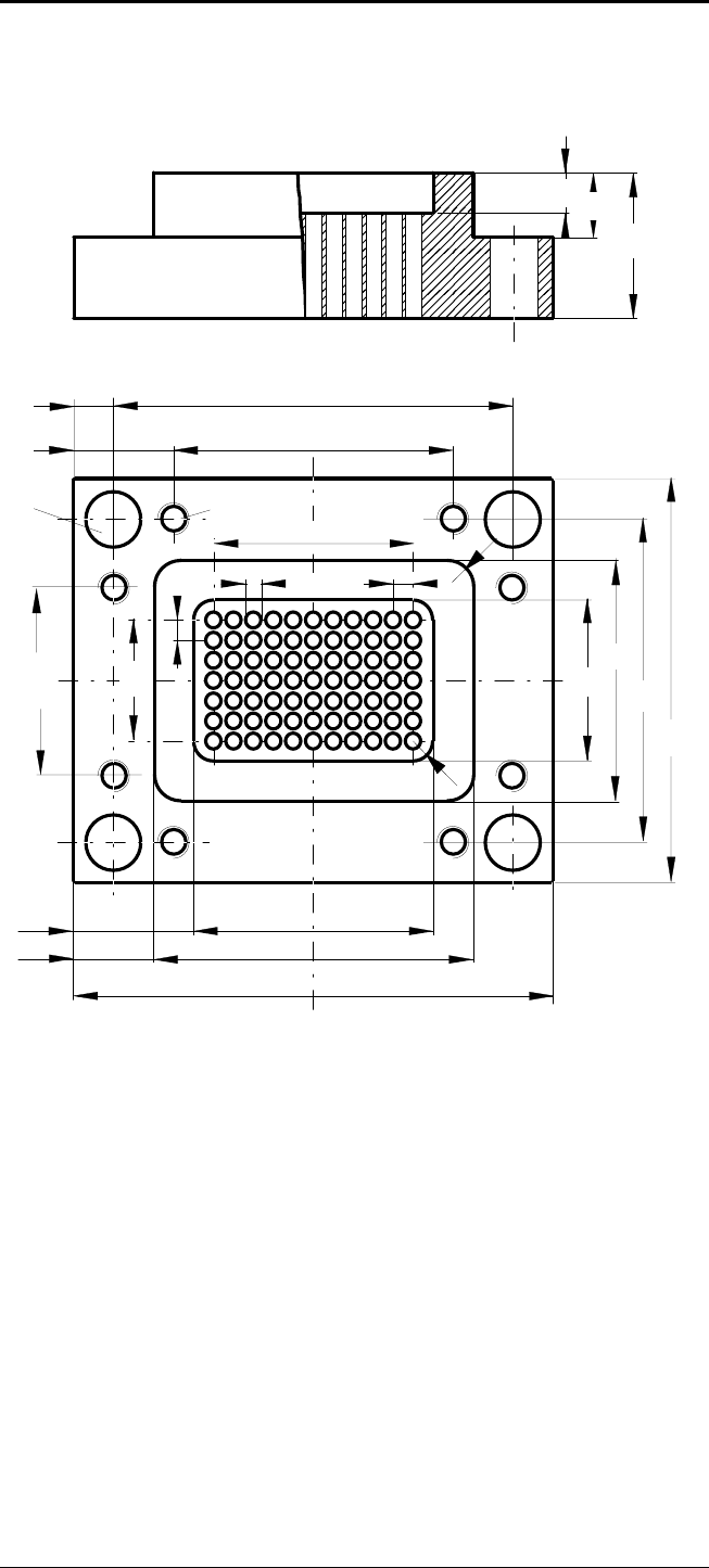
- Page 121GFKE-0041A-EN Detailed Programming Examples B. 8. 1 Example AUXILIARY : INITIAL SETTING 1/2 198 MATERIAL : Q= GRAUGUSS X AXIS : X= * WORK SHAPE : C= VIERCK PAR COOLANT : M= COOLNT M8 Y AXIS : Y= * MAT X CO-ORD:YA= -105 Endpunkt Z SAFTY LMT: I= 50 .Z AXIS : Z= * MAT Y CO-ORD:YB= -95 R20 COORDINATES:
- Page 122GFKE-0041A-EN Detailed Programming Examples CONTOUR FORM (APPROACH) TANG B. 8. 2 Example B = R = 86 A = CIR.TAN-R 198 I = 0 X = 0 J = 0 Y = -86 CIRCLE END X = 0 Endpunkt D = RIGHT-R = 30 R20 CIRCLE END Y/K = 86 I = 30 POINT 2 B = 172 R = 86 + 55 I = 0 SYMET- X = 0 J = 0 TRY CO Y = 0 10 TANG START PO
- Page 123GFKE-0041A-EN Detailed Programming Examples B. 8. 3 Example Important detail X99 Y-10 define as circle end point Center not known TANGENT Startpunkt GEF #FL / escapm-08-012000 - B 21 -�
- Page 124
- Page 125Revision Record SUPER CAP i-M DATA SETTING MANUAL (GFKE-0041A-EN) 01 Jan.,2000 Edition Date Contents Edition Date Contents
- Page 126EUROPEAN HEADQUARTERS – BELGIUM / NETHERLANDS GRAND-DUCHÉ DE LUXEMBOURG GE Fanuc Automation Europe S.A. GE Fanuc Automation Europe S.A. - Netherlands Branch - Zone Industrielle Postbus 7230 - NL-4800 GE Breda L-6468 Echternach Minervum 1603A - NL-4817 ZL Breda ( (+352) 727979 - 1 ( (+31) 76-5783 201
- Page 127• No part of this manual may be reproduced in any form. • All specifications and designs are subject to change without prior notice. The export of this product is subject to the authorization of the government of the country from where the product is exported. In this manual we have tried as much as