DIGITAL SERVO ADAPTER Maintenance manual Page 78
Maintenance manual
2. HARDWARE
B–63465EN/01
62
Generally, noise is generated by electrostatic coupling, electromagnetic
induction, and ground looping, and introduced to the Digital Servo
Adapter. However, it is difficult to measure the level and frequency of
noise quantitatively, and noise has many uncertain factors. It is important
to prevent both noise from being generated and generated noise from
being introduced into the Digital Servo Adapter. This precaution
improves the stability of the Digital Servo Adapter machine system.
The Digital Servo Adapter component units are often installed close to the
parts generating noise in the power magnetics cabinet. Possible noise
sources into the Digital Servo Adapter are capacitive coupling,
electromagnetic induction, and ground loops.
When designing the power magnetics cabinet, guard against noise in the
machine as described in the following section.
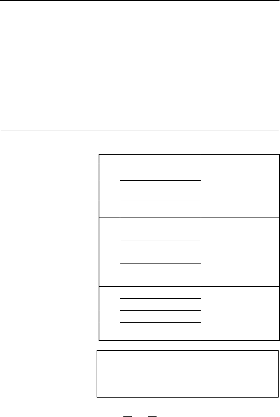
The cables used for the machine are classified as listed in the following table:
Process the cables in each group as described in the action column.
Group Signal line Action
Primary AC power line
Bind the cables in group A
Secondary AC power line
separately (Note 1) from groups B
A
AC/DC power lines (containing the
power lines for the servo and
spindle motors)
and C, or cover group A with an
electromagnetic shield (Note 2).
See Section 2.11.4 and connect
AC/DC solenoid
spark killers or diodes with the
solenoid and relay.
AC/DC relay
solenoid and relay.
DC solenoid (24VDC)
Connect diodes with DC solenoid
and relay.
Bind the cables in group B
B
DC relay (24VDC)
separately from group A, or cover
group B with an electromagnetic
shield.
Separate group B as far from
DC power line
Separate group B as far from
Group C as possible.
It is more desirable to cover group
B with the shield.
Feedback cable
Bind the cables in group C
separately from group A, or cover
RS–232–C interface cable
separately from group A, or cover
group C with an electromagnetic
shield.
C
Cable for the battery
shield.
Separate group C as far from
Other cables to be covered with
the shield
Group B as possible.
Be sure to perform shield
processing in Section 2.11.5.
NOTE
1 The groups must be 10 cm or more apart from one another
when binding the cables in each group.
2 The electromagnetic shield refers to shielding between
groups with grounded steel plates.
2.11
ACTION AGAINST
NOISE
2.11.1
Separating Signal
Lines
Contents Summary of DIGITAL SERVO ADAPTER Maintenance manual
- Page 1MAINTENANCE MANUAL B-63465EN/01�
- Page 2Ȧ No part of this manual may be reproduced in any form. Ȧ All specifications and designs are subject to change without notice. In this manual we have tried as much as possible to describe all the various matters. However, we cannot describe all the matters which must not be done, or which cannot be
- Page 3SAFETY PRECAUTIONS This section describes the safety precautions related to the use of FANUC Digital Servo Adapter. It is essential that these precautions be observed by users to ensure the safe operation of machines equipped with a Digital Servo Adapter (all descriptions in this section assume this
- Page 4SAFETY PRECAUTIONS B–63465EN/01 1 DEFINITION OF WARNING, CAUTION, AND NOTE This manual includes safety precautions for protecting the maintenance personnel (herein referred to as the use) and preventing damage to the machine. Precautions are classified into Warnings and Cautions according to their b
- Page 5B–63465EN/01 SAFETY PRECAUTIONS 2 WARNINGS, CAUTIONS, AND NOTES RELATED TO CHECK OPERATION WARNING 1. When checking the operation of the machine with the cover removed (1) The user’s clothing could become caught in the components, thus presenting a danger of injury. When checking the operation, stan
- Page 6SAFETY PRECAUTIONS B–63465EN/01 3 WARNINGS AND NOTES RELATED TO REPLACEMENT WARNING 1. Always turn off the power to the Digital Servo Adapter and the main power to the power magnetics cabinet. If only the power to the Digital Servo Adapter is turned off, power may continue to be supplied to the serv
- Page 7B–63465EN/01 SAFETY PRECAUTIONS 4 WARNINGS AND NOTES RELATED TO PARAMETERS WARNING 1. When machining a workpiece for the first time after modifying a parameter, close the machine cover. Never use the automatic operation function immediately after such a modification. Instead, confirm normal machine
- Page 8SAFETY PRECAUTIONS B–63465EN/01 5 WARNINGS RELATED TO DAILY MAINTENANCE WARNING 1. Memory backup battery replacement When replacing the memory backup batteries, keep the power to the machine (Digital Servo Adapter) turned on, and apply an emergency stop to the machine. Because this work is performed
- Page 9B–63465EN/01 SAFETY PRECAUTIONS WARNING 2. Absolute pulse coder battery replacement When replacing the memory backup batteries, keep the power to the machine (Digital Servo Adapter) turned on, and apply an emergency stop to the machine. Because this work is performed with the power on and the cabine
- Page 10SAFETY PRECAUTIONS B–63465EN/01 WARNING 3. Fuse replacement Before replacing a blown fuse, however, it is necessary to locate and remove the cause of the blown fuse. For this reason, only those personnel who have received approved safety and maintenance training may perform this work. When replacing
- Page 11B–63465EN/01 PREFACE PREFACE Description of 1.Display and operation this manual This chapter covers those items, displayed on the screen, that are related to maintenance. A list of all supported operations is also provided at the end of this chapter. It also presents a list of operations. 2.Hardware
- Page 12PREFACE B–63465EN/01 Applicable models This manual can be used with the following models. The abbreviated names may be used. Pruduct name Abbreviation FANUC Digital Servo Adapter Digital Servo Adapter DSA Related manuals The table below lists manuals related to Digital Servo Adapter. In the table, t
- Page 13B–63465EN/01 Table of Contents SAFETY PRECAUTIONS . . . . . . . . . . . . . . . . . . . . . . . . . . . . . . . . . . . . . . . . . . . . . . . . . . . . . s–1 PREFACE . . . . . . . . . . . . . . . . . . . . . . . . . . . . . . . . . . . . . . . . . . . . . . . . . . . . . . . . . . . . . . . . . .
- Page 14TABLE OF CONTENTS B–63465EN/01 2.6.3 Mounting and Demounting DIMM Modules . . . . . . . . . . . . . . . . . . . . . . . . . . . . . . . . . . . . . . . 46 2.6.4 Methods for Dismounting and Mounting the HSSB Board . . . . . . . . . . . . . . . . . . . . . . . . . . . . 48 2.6.5 Methods for Dismountin
- Page 15B–63465EN/01 TABLE OF CONTENTS APPENDIX A. ALARM LIST . . . . . . . . . . . . . . . . . . . . . . . . . . . . . . . . . . . . . . . . . . . . . . . . . . . . . . . . . . . . . 107 A.1 LIST OF ALARM CODES . . . . . . . . . . . . . . . . . . . . . . . . . . . . . . . . . . . . . . . . . . . . . . . .
- Page 16TABLE OF CONTENTS B–63465EN/01 E.2 BACKUP USING A FLASH MEMORY CARD . . . . . . . . . . . . . . . . . . . . . . . . . . . . . . . . . . . . . . . 138 E.3 BACKUP ONTO THE HARD DISK OF THE PC . . . . . . . . . . . . . . . . . . . . . . . . . . . . . . . . . . . . . . 138 E.4 DATA BACKUP ONTO A FLOPPY
- Page 17B–63465EN/01 1. DISPLAY AND OPERATION 1 DISPLAY AND OPERATION This chapter describes how to display various screens by the function keys. The screens used for maintenance are respectively displayed. 1.1 KEYS OF DPL/MDI . . . . . . . . . . . . . . . . . . . . . . . . . . . 2 1.2 SCREENS WHEN POWER SU
- Page 181. DISPLAY AND OPERATION B–63465EN/01 1.1 KEYS OF DPL/MDI Function key / AND Date input key 9 Q Program edit key Input key Cursor move key Fig.1.1 DPL/MDI Panel (1) Function keys Function keys indicate large items like chapters in a document. Indicates the current position. Used to set and display s
- Page 19B–63465EN/01 1. DISPLAY AND OPERATION (2) Keyboard functions Table 1.1 MDI Keyboard functions Key Functions Address /numerical key Press these keys to input alphabetic, numeric, and other characters. When an address or a numerical key is pressed, the letter or the numeral is input INPUT ( ) key once
- Page 201. DISPLAY AND OPERATION B–63465EN/01 1.2 SCREENS WHEN POWER SUPPLY IS ON 1) Upon normal start DSA Digital Servo 881G–01 Adapter control software 2) When the DPL/MDI has started normally, but cannot communicate with the controller ROM PARI. OK RAM CHECK OK NOTE If nothing appears on the screen, it i
- Page 21B–63465EN/01 1. DISPLAY AND OPERATION 1.3 DISPLAYING DIAGNOSTIC PAGE 1.3.1 Procedure of (1) Press the key to select the diagnosis screen. Displaying When input signal X1000 data is displayed, operate ³ Number ³ in turn. > @0000 0 @0010 1 Following are display methods in the diagnostic screen of inpu
- Page 221. DISPLAY AND OPERATION B–63465EN/01 1.3.2 Diagnostic Data Indications RS–232C–related and If a problem arises when an RS–232C interface is used to input or output other indications parameters, the status can be determined by the following: 010 Reader/punch interface output in progress (RS–232C) 01
- Page 23B–63465EN/01 1. DISPLAY AND OPERATION #7 #6 #5 #4 #3 #2 #1 #0 201 ALD EXP When OVL of diagnostic indication No. 200 is 1: ALD 1 : The motor is overheated. 0 : The servo amplifier is overheated. When FBA of diagnostic indication No. 200 is 1: ALD EXP Alarm details 1 0 The built–in pulse coder contain
- Page 241. DISPLAY AND OPERATION B–63465EN/01 STB: A communication failure has occurred in the serial pulse coder, due to an abnormality in the pulse coder, feedback cable, or feedback receiving circuit. Replace the pulse coder, feedback cable, or servo card. PRM: An invalid–parameter alarm has been issued.
- Page 25B–63465EN/01 1. DISPLAY AND OPERATION XE0: (Reserved) XE1: Broken wire in the slave port XE2: Broken wire in the master port XE3: External EMG input #7 #6 #5 #4 #3 #2 #1 #0 330 EXT DUA ST1 ST0 #7 #6 #5 #4 #3 #2 #1 #0 332 EXT DUA ST1 ST0 : : #7 #6 #5 #4 #3 #2 #1 #0 348 EXT DUA ST1 ST0 ST0, ST1: The t
- Page 261. DISPLAY AND OPERATION B–63465EN/01 Correspondences between slave units and diagnostic indications Slave unit 01: Diagnostic indications No. 330 and No. 331 Slave unit 02: Diagnostic indications No. 332 and No. 333 Slave unit 03: Diagnostic indications No. 334 and No. 335 Slave unit 04: Diagnostic
- Page 27B–63465EN/01 1. DISPLAY AND OPERATION 1.4 LIST OF OPERATIONS (DPL/MDI) Classifi- KEY SETTING Function Function Mode Operation cation SW PWE=1 key Clear All memory clear Power ON – <7>AND<9> Parameter clear Ę Power ON – Alarm clear –
or Power OFF/ON Registra- Parameter input Ę – DGNOS/ - Page 281. DISPLAY AND OPERATION B–63465EN/01 1.5 When no setting/display unit is connected to the Digital Servo Adapter, simple maintenance operations such as the display of the status of the LIST OF Digital Servo Adapter and save and restore operation of files in a batch OPERATIONS can be performed just u
- Page 29B–63465EN/01 2. HARDWARE 2 HARDWARE This chapter describes structure of Digital Servo Adapter control section, connection of units and the functions of PCBs and modules mounted on PCBs. 2.1 TOTAL CONNECTION DIAGRAM . . . . . . . . . . . . . 14 2.2 CONFIGURATION OF THE UNIT . . . . . . . . . . . . .
- Page 302. HARDWARE B–63465EN/01 2.1 TOTAL CONNECTION DIAGRAM Base PCB JD1B JD1A 24V–IN(CP1) J30 24VDC power 24V–OUT(CP2) I/O device, and etc. JD41 RS–232–C(JD42) J146 RS–232–C I/O device JA47 (Emergency stop) J86 Built–in I/O(CB155) CB156 DPL/MDI JD1A1 Operator’s panel RS–422(JD40) 14
- Page 31B–63465EN/01 2. HARDWARE JA46 JA11 Servo card TB2 CX2A JX1A 1st axis FSSB COP10B TB2 servo motor (COP10A) SVM JF1 COP10A TB1 CX2B JX1B 2nd axis COP10B SVM servo motor COP10A 3rd axis COP10B SVM servo motor COP10A COP10B 4th axis SVM servo motor COP10A to 8th axis servo motor Separate detector interf
- Page 322. HARDWARE B–63465EN/01 2.2 CONFIGURATION OF THE UNIT 2.2.1 The control units of the Digital Servo Adapter consist of below Configuration of the components. Control Unit Table 2.2.1 Configuration of the control unit No. Name Remarks 1 Control unit 2 Fan unit 3 Back panel Connection port of the firs
- Page 33B–63465EN/01 2. HARDWARE 2.2.2 Connector Locations on the Control Unit Front Bottom face Battery Not used Not used Not used Memory card Not used Not used Not used Not used DPL/MDI Fuse diagnose display LED Left CP2 24VDC output Right CP1 24VDC input Left CB156 Unused Right CB155 Emergency step input
- Page 342. HARDWARE B–63465EN/01 2.2.3 The Digital Servo Adapter has the following LEDs and switches. LEDs and Switches on the Control Units D 7–segment LED (LEDM1) LEDM1 displays the status information of the Digital Servo Adapter. It is used along with the MTSW rotary switch and PSW pushbutton switch also
- Page 35B–63465EN/01 2. HARDWARE Front view LEDM2: Blown fuse indicator LED LEDM1: LED indicator MTSW: Rotary switch PSW: Pushbutton switch Fig. 2.2.3 LEDs and switches on the control units 19
- Page 362. HARDWARE B–63465EN/01 2.2.4 The Digital Servo Adapter is equipped with a fan unit. It is easy to Fan Unit Configuration dismount and mount. There are two fans on the fan unit. Their cables are connected to the fan connection printed–circuit board. Each fan cable connector on the fan connection pr
- Page 37B–63465EN/01 2. HARDWARE 2.2.5 The Digital Servo Adapter system software consists of the components System Software listed below: Configuration Name Specification Storage location Remark Digital Servo Adapter basic function A03B–0818–H501#881G Memory module Functions including commu- nication with t
- Page 382. HARDWARE B–63465EN/01 2.3 CONFIGURATION OF PRINTED CIRCUIT BOARD AND LED DISPLAY 2.3.1 Base Printed Circuit Board D Specification Name Specification Base printed circuit board A16B–3200–0260 22
- Page 39B–63465EN/01 2. HARDWARE D Connector and LED locations CNM1B: Memory card BAT1: Battery JD41 CPU: JA47 CPU card JD42: RS–232–C JD1A1 JA11 JA46 JD40: DPL/MDI LEDM2: Blown fuse indicator LED POS AI CP1 (lower): 24 VDC input FUS1 CP2 (upper): 24 VDC output Huse CB155 (lower): Built–in I/O CB156 Short p
- Page 402. HARDWARE B–63465EN/01 2.3.2 Card PCB D Mounting location (1) CPU card (2) Axis control card D Specification No. Name Specification Function Remarks (1) CPU card A A20B–3300–0071 Digital Servo Adapter 486DX2 control CPU card C A20B–3300–0171 MMX–Pentium (2) Axis control card A20B–3300–0121 Axis co
- Page 41B–63465EN/01 2. HARDWARE 2.3.3 Memory Module D Mounting location (1) Memory module D Specification No. Name Specification Function Remarks (1) 4M/256K A20B–3900–0080 FROM 4MB Memory module SRAM 256KB NOTE The memory module is under the axis control card. 25
- Page 422. HARDWARE B–63465EN/01 2.3.4 DRAM Module D Mounting location (2) DRAM module Connector DRAM module socket CPU card Side–B D Specification No. Name Specification Function Remarks (2) 4M SDRAM A20B–3900–0132 SDRAM 4MB For CPU card C module 4M DRAM A20B–3900–0042 DRAM 4MB For CPU card A module NOTE D
- Page 43B–63465EN/01 2. HARDWARE 2.3.5 Fan Connection Printed–circuit Board D Specification Name Specification Fan connection PCB A20B–9002–0240 D Connector locations Connector for connecting fan 1, Connector for CA39A connecting fan 2, CA39B Connector for connecting the base printed– circuit board, CN3 27
- Page 442. HARDWARE B–63465EN/01 2.3.6 Backpanel D Specification Name Specification Backpanel A20B–2002–0680 D Connector locations Test Slot 2 connector, connection, JNATP JNA1P Slot 1 Base printed– connection, circuit board JNA1P connection, JNAM 28
- Page 45B–63465EN/01 2. HARDWARE 2.3.7 High–speed Serial Bus (HSSB) Board D Specification Name Printed–circuit board specification High–speed serial bus (HSSB) board A20B–8001–0730 D Connector and LED locations LED B LED A LED 4 LED 3 LED 2 LED 1 High–speed serial bus setting switch, SW1 Connector for High–
- Page 462. HARDWARE B–63465EN/01 Green LED status display J : on and j : off 4 3 2 1 Status JJJJ The power has just been switched on. JJJj The HSSB board is being initialized. JJjJ The HSSB is waiting for the host controller to complete booting. Jjjj Start–up has been completed normally, and the regular ope
- Page 47B–63465EN/01 2. HARDWARE 2.3.8 Basic Unit of the Separate Detector Interface Unit D Specification Name Specification Basic unit of the separate detector A20B–2100–0270 interface unit D Connector and LED locations Power supply connector On the board side: CP11B On the upper side: CP11A Connector for
- Page 482. HARDWARE B–63465EN/01 2.3.9 Expansion Unit of the Separate Detector Interface Unit D Specification Name Specification Expansion unit of the separate A20B–2002–0570 detector interface unit D Connector and LED locations Connector for connection with the basic unit, Connector JF105 CNF2 JF106 JF107
- Page 49B–63465EN/01 2. HARDWARE 2.4 LIST OF UNITS AND PRINTED CIRCUIT BOARDS 2.4.1 Control Unit Name Specification Remarks Digital Servo Adapter A03B–0818–B101 basic unit CPU card C A02B–0259–H003 MMX–Pentium CPU card A A02B–0259–H002 486DX2 2 axes control card A02B–0259–H015 For high–speed response 4 axes
- Page 502. HARDWARE B–63465EN/01 2.4.4 Printed Circuit Boards of the Control Unit Type Name Specifications Remarks Base PCB Base PC board A16B–3200–0260 Card PCB CPU card A20B–3300–0171 MMX–Pentium A20B–3300–0071 486DX2 Axis control card A20B–3300–0121 2 axes/high speed A20B–3300–0120 4 axes/high speed A17B
- Page 51B–63465EN/01 2. HARDWARE 2.5 METHODS FOR WARNING DISMOUNTING AND When opening the cabinet and replacing a fan unit, be MOUNTING FAN careful not to touch the high–voltage circuits (marked and UNITS AND FANS fitted with an insulating cover). Touching the uncovered high–voltage circuits presents an ext
- Page 522. HARDWARE B–63465EN/01 (2) Put your finger on the lower section of the front surface of the fan unit, and lift it up. Lift up the fan unit. (3) Lift up the fan unit until it is tilted to about 30 degrees. (4) Dismount the fan unit by pulling it upward and toward you. (3)Lift this portion of the fa
- Page 53B–63465EN/01 2. HARDWARE (4) Push down the latch on the upper section of the fan unit to latch it. Push down the latch. Unlatched state Latched state (5) Switch on the power, and make sure that no fan alarm condition does not occur and that both fans are rotating. NOTE 1 If the fan unit has not been
- Page 542. HARDWARE B–63465EN/01 (5) Attach the cable connector of a replacement fan to the left–side connector (CA39A) on the fan connection printed–circuit board first, and place the fan at a location labeled FAN1 with the cable held to the right, then latch it. Be sure to lay the fan cable under FAN2. FA
- Page 55B–63465EN/01 2. HARDWARE 2.6 METHODS FOR WARNING DISMOUNTING AND Do not dismount or mount printed–circuit boards unless you MOUNTING have received maintenance and safety training. PRINTED–CIRCUIT When opening the cabinet and replacing a printed–circuit BOARDS board, be careful not to touch the high–
- Page 562. HARDWARE B–63465EN/01 2.6.1 Methods for Dismounting and CAUTION 1 The fan unit must be removed before the base Mounting the Base printed–circuit board can be dismounted. If you attempt to Printed–circuit Board dismount the base printed–circuit board without removing the fan unit, both the fan uni
- Page 57B–63465EN/01 2. HARDWARE Mounting procedure 1) Hold the base printed–circuit board by grabbing its handles, A and B, and insert it into the rack all the way through, then engage it with the backpanel connector. 2) Place the fan unit back into the previous location by following the mounting procedure
- Page 582. HARDWARE B–63465EN/01 Replacement procedure CAUTION 1 Before replacing the base printed–circuit board, remove the card PCBs and DIMM modules on the base printed–circuit board, and mount them on a new base printed–circuit board. As the memory module is removed, the SRAM memory contents are erased.
- Page 59B–63465EN/01 2. HARDWARE 2.6.2 Mounting and Demounting Card CAUTION 1 The base printed–circuit board must be removed before the PCBS PCB card can be dismounted and mounted. Observe the CAUTIONS in Section 2.6.1. 2 Be careful not install the PCB card in an incorrect location. Otherwise, the printed–c
- Page 602. HARDWARE B–63465EN/01 Demounting a card PCB 1) Dismount the base printed–circuit board by following the dismounting procedure described in Section 2.6.1. 2) Pull outward the claw of each of the four spacers used to secure the card PCB, then release each latch. (See Fig. a.) 3) Extract the card PC
- Page 61B–63465EN/01 2. HARDWARE Mounting a card PCB 1) Check that the claw of each of the four spacers is latched outward, then insert the card PCB into the connector. (See Fig. c.) 2) Push the claw of each spacer downward to secure the card PCB. (See Fig. d.) 3) Mount the base printed–circuit board by fol
- Page 622. HARDWARE B–63465EN/01 2.6.3 The DIMM module in the Digital Servo Adapter is either a memory or Mounting and DRAM module. Demounting DIMM The memory module is installed on the DIMM connector on the base printed–circuit board. To dismount the memory module, it is necessary Modules to remove the axi
- Page 63B–63465EN/01 2. HARDWARE Demounting a DIMM 1) Open the claw of the socket outward. (See Fig. a.) Module 2) Extract the module slantly upward. (See Fig. b.) Mounting a DIMM 1) Insert the module slantly into the module socket, with side B facing Module upward. (See Fig. b.) 2) Push the module downward
- Page 642. HARDWARE B–63465EN/01 2.6.4 Methods for Dismounting and Mounting the HSSB Board Dismounting procedure 1) To pull out the HSSB board, first detach any interfering cable. (Make sure that the detached cable is labeled the number of the mating connector.) 2) Hold the HSSB board by grabbing its handle
- Page 65B–63465EN/01 2. HARDWARE 2.6.5 Methods for Dismounting and Mounting the Backpanel Dismounting procedure 1) Remove the base printed–circuit board and HSSB board in advance by referring to Sections 2.6.1 and 2.6.4. 2) Detach latch A from the backpanel. (See Fig. 2.6.5.) 3) Detach latches B and C also.
- Page 662. HARDWARE B–63465EN/01 2.6.6 Methods for Dismounting and Mounting the Fan Connection Printed–circuit Board Dismounting procedure 1) Dismount the fan unit by following the fan unit dismounting procedure described in Section 2.5.2. 2) Detach the fan cables from the fan connection printed–circuit boa
- Page 67B–63465EN/01 2. HARDWARE 2.7 REPLACING THE WARNING FUSE Before replacing a blown fuse, it is necessary to remove the cause of the blown fuse. For this reason, only the personnel who have a working knowledge of maintenance and safety are allowed to carry out this work. When replacing a fuse with the
- Page 682. HARDWARE B–63465EN/01 Base PC board LEDM2 CPU card FUS1 Power supply connector CP1/CP2 Fuse Built–in I/O connector Axis control card Fig.2.7.1 Location of controller fuse 52
- Page 69B–63465EN/01 2. HARDWARE 2.8 BATTERY REPLACEMENT 2.8.1 The parameters are stored in the SRAM on the control unit. The power Battery for Memory to the SRAM memory is backed up by a lithium battery mounted on the front panel of the control unit. Even when the main power supply is Backup (3 VDC) turned
- Page 702. HARDWARE B–63465EN/01 Battery latch Battery connector Lithium battery (5) Remove the old battery, insert a new one into the battery holder, and attach the connector. Confirm that the battery is latched firmly. WARNING Using other than the recommended battery may result in the battery exploding. R
- Page 71B–63465EN/01 2. HARDWARE Dispose of used batteries as follows. (1) Small quantities (less than 10) Discharge the batteries and dispose of them as ordinary unburnable waste. (2) Large quantities Please consult FANUC. Replacing the alkaline (1) Prepare two new alkaline dry cells (size D). dry cells (s
- Page 722. HARDWARE B–63465EN/01 2.8.2 Replacing Batteries for Absolute Pulse Coder WARNING Absolute pulse coder battery replacement (Servo Amplifier α When replacing the memory backup batteries, keep the Series) power to the machine (servo amplifier) switched on, and hold the machine at an emergency stop.
- Page 73B–63465EN/01 2. HARDWARE WARNING Using other than the recommended battery may result in the battery exploding. Replace the battery only with the specified type (A06B–0073–K001). CAUTION 1 Replace the batteries for absolute pulse coder when servo amplifier power is ON. Replacing the batteries with po
- Page 742. HARDWARE B–63465EN/01 Procedure for replacing batteries for absolute pulse coder Procedure (1) Turn machine (servo amplifier) power ON. (2) Remove the battery case from under the β series servo amplifier module by holding the case at both sides and pulling downwards. 6V litium battery for absolut
- Page 75B–63465EN/01 2. HARDWARE 2.8.4 Prepare 4 alkaline batteries (UM–1type) commercially available in Replacing Batteries in advance. the Separate Battery Case Procedure for replacing batteries for absolute pulse coder Procedure (1) Turn machine (servo amplifier) power ON. (2) Loosen screws on the batter
- Page 762. HARDWARE B–63465EN/01 2.9 The peripheral units and the control unit have been designed on the assumption that they are housed in closed cabinets. In this manual ENVIRONMENTAL “cabinet” refers to the following: REQUIREMENTS D Cabinet for housing the control unit or peripheral units; D Operation pe
- Page 77B–63465EN/01 2. HARDWARE 2.10 The following unit requires a power supply of 24 VDC "10% (including instantaneous change and ripple). POWER SUPPLY Table 2.10 Power supply capacity and calorific value CAPACITY AND CALORIFIC VALUE Unit Power supply capacity Calorific value Control unit of 1.7 A (Anothe
- Page 782. HARDWARE B–63465EN/01 2.11 Generally, noise is generated by electrostatic coupling, electromagnetic induction, and ground looping, and introduced to the Digital Servo ACTION AGAINST Adapter. However, it is difficult to measure the level and frequency of NOISE noise quantitatively, and noise has m
- Page 79B–63465EN/01 2. HARDWARE Cabinet Servo Servo Digital amp. amp. Servo Adapter Cable of group B, C Duct To operator’s panel, motor, etc. Cable of group A Section Group A Group B, C Cover 2.11.2 The following ground systems are provided for the machine : Ground D Ground for signal The ground for signal
- Page 802. HARDWARE B–63465EN/01 2.11.3 Connect the ground terminal for signals of the Digital Servo Adapter (FG Connecting the Ground terminal) to the grounded plate of the cabinet. Terminal for Signal Cabinet FG terminals (Fastonterminals at the controller) To the other grounded plates Distribution switch
- Page 81B–63465EN/01 2. HARDWARE 2.11.4 The AC/DC solenoid and relay are used in the power magnetics cabinet. Noise Suppressor A high pulse voltage is caused by coil inductance when these devices are turned on or off. This pulse voltage induced through the cable causes the electronic circuits to be disturbe
- Page 822. HARDWARE B–63465EN/01 Diode Diode (used for direct–current circuits) – + Diode Use a diode which can withstand a DC relay voltage up to two times the applied voltage and a current up to two times the applied current. 2.11.5 If a cable connected to the Digital Servo Adapter, servo amplifier, or ot
- Page 83B–63465EN/01 2. HARDWARE ÇÇ Machine side installation ÇÇ board ÇÇ Control unit ÇÇ ÇÇ ÇÇ ÇÇ ÇÇ ÇÇ ÇÇ ÇÇ Ground plate ÇÇ ÇÇ ÇÇ Metal fittings ÇÇ ÇÇ for clamp Shield cover Fig. 2.11.5 (b) Cable clamp (2) Prepare ground plate like the following figure. Ground terminal (grounded) Hole for securing metal
- Page 842. HARDWARE B–63465EN/01 Ground 8mm plate 12mm 20mm Fig. 2.11.5 (d) Ground plate holes (Reference) Outer drawings of metal fittings for clamp. Max. 55mm 28mm 6mm 17mm Fig. 2.11.5 (e) Outer drawings of metal fittings for clamp Ordering specification for metal fittings for clamp A02B–0124–K001 (8 piec
- Page 85B–63465EN/01 3. INPUT AND OUTPUT OF DATA 3 INPUT AND OUTPUT OF DATA Once the memory module or base printed–circuit board is replaced, or the memory is cleared, it becomes necessary to re–set data in the memory. This chapter explains how to input parameters from an external I/O unit, such as a Handy
- Page 863. INPUT AND OUTPUT OF DATA B–63465EN/01 3.1 1. Set emergency stop. SETTING 2. Press the key to display the settings screen. PARAMETERS 3. Use the cursor keys to position the cursor at PWE, then press the PROCEDARE (DPL/MDI) key and the key, in that order, to enable parameters to be written. The Dig
- Page 87B–63465EN/01 3. INPUT AND OUTPUT OF DATA 3.2 The Digital Servo Adapter memorized the following data. Save a backup copy of the latest data to the flash memory card or an I/O INPUTTING/ unit beforehand, while the controller is running normally. OUTPUTTING DATA (1) Paramter 3.2.1 Be sure that data inp
- Page 883. INPUT AND OUTPUT OF DATA B–63465EN/01 3.2.2 Outputting Parameters D Procedure (DPL/MDI) 1. Set emergency stop. 2. Select the parameter display screen by key. 3. Press the key. 4. While parameter, is being output, the display appears as below. >&0001 00000000 WRITE Explanations (Output to a floppy
- Page 89B–63465EN/01 4. DIGITAL SERVO 4 DIGITAL SERVO This chapter describes servo parameters required for maintenance of digital servo and adjustment of reference position. 4.1 INITIAL SETTING SERVO PARAMETERS . . . . . . . 74 73
- Page 904. DIGITAL SERVO B–63465EN/01 4.1 This section describes how to set initial servo parameters, which is used for field adjustment of machine. INITIAL SETTING 1. Turn on power at the emergency stop condition. SERVO 2. Input data required for initial setting using the cursor and page key. PARAMETERS (1
- Page 91B–63465EN/01 4. DIGITAL SERVO For a L series servo motor Model name a L3/3000 a L6/2000 a L9/3000 a L25/3000 a L50/2000 Drawing number 0561 0562 0564 0571 0572 Format number 56 or 68 57 or 69 58 or 70 59 60 For a C series servo motor Model name a C3/2000 a C6/2000 a C12/2000 a C22/1500 Drawing numbe
- Page 924. DIGITAL SERVO B–63465EN/01 (5) Feed gear n/m 2084 n for flexible feed gear 2085 m for flexible feed gear 1) For serial pulse coder A or B, and serial a pulse coder. n Number of feedback pulses per revolution of motor = m 1000000 NOTE For serial pulse coder B, use a value not exceeding 250,000 as
- Page 93B–63465EN/01 4. DIGITAL SERVO 3. Turn off the power then back on. (8) FSSB setting Connecting the control unit to servo amplifiers via a high–speed serial bus (FANUC Serial Servo Bus, or FSSB), which uses only one fiber optics cable, can significantly reduce the amount of cabling in machine tool ele
- Page 944. DIGITAL SERVO B–63465EN/01 S When a three–axis amplifier is used, the requirement for a two–axes amplifier described above applies to the first and second axes, and the requirement for a one–axis amplifier, again described above, applies to the third axis. S When an odd number is specified for pa
- Page 95B–63465EN/01 4. DIGITAL SERVO 1910 Address conversion table value for slave 1 (ATR) 1911 Address conversion table value for slave 2 (ATR) 1912 Address conversion table value for slave 3 (ATR) 1913 Address conversion table value for slave 4 (ATR) 1914 Address conversion table value for slave 5 (ATR)
- Page 964. DIGITAL SERVO B–63465EN/01 S Examples of axis configurations and parameter settings (1) Optical cable DSA 1–axis 2–axes 2–axes M1 1–axis M2 amplifier amplifier amplifier amplifier X Y Z A B C axis axis axis axis axis axis When a connection is established as shown in the above example, the corresp
- Page 97B–63465EN/01 4. DIGITAL SERVO (2) Optical cable DSA 1–axis 2–axes 2–axes 1–axis M2 M1 amplifier amplifier amplifier amplifier X A Y Z B C axis axis axis axis axis axis When a connection is established as shown in the above example, the correspondences between parameters and settings are as follows.
- Page 984. DIGITAL SERVO B–63465EN/01 (3) Optical cable DSA 1–axis 2–axes 2–axes 1–axis M1 M2 amplifier amplifier amplifier amplifier X A Y Z B C axis axis axis axis axis axis When a connection is established as shown in the above example, the correspondences between parameters and settings are as follows.
- Page 99B–63465EN/01 4. DIGITAL SERVO (4) Optical cable DSA 1–axis 1–axis 2–axes 1–axis 1–axis amplifier amplifier amplifier amplifier amplifier X Y Z A axis axis axis axis When a connection is established as shown in the above example, the correspondences between parameters and settings are as follows. Not
- Page 1004. DIGITAL SERVO B–63465EN/01 1936 Connector number of the first pulse module 1937 Connector number of the second pulse module NOTE After these parameters have been set, the power must be turned off then back on for the settings to become effective. [Data type] Byte axis [Valid data range] 0 to 7 Wh
- Page 101B–63465EN/01 5. TROUBLESHOOTING 5 TROUBLESHOOTING This chapter describes troubleshooting procedure. 5.1 CORRECTIVE ACTION FOR FAILURES . . . . . . . . 86 5.2 POWER CANNOT BE TURNED ON . . . . . . . . . . . . 88 5.3 ALARM 85 TO 87 (READER/PUNCHER INTERFACE ALARM) . . . . . . . . . . . . . . . . . . .
- Page 1025. TROUBLESHOOTING B–63465EN/01 5.1 When a failure occurs, it is important to correctly grasp what kind of failure occured and take appropriate action, to promptly recover the CORRECTIVE machine. ACTION FOR Check for the failure according to the following procedure : FAILURES When? With what What fa
- Page 103B–63465EN/01 5. TROUBLESHOOTING 4 Other information ⋅ Is there noise origin around machine? If the failure has not occurred frequently, the cause may be external noise to the power supply or inductive noise on machinery cables. Operate other machines connected to the same power line and see if noise
- Page 1045. TROUBLESHOOTING B–63465EN/01 5.2 POWER CANNOT BE TURNED ON Points If the 7–segment LED, LEDM1, is not lit when the 24–V power is turned on, check LEDM2, the red LED on the front of the controller. When LEDM2 is lit, the fuse for the Digital Servo Adapter is blown. Causes and Remedies (1) FUS1 (fu
- Page 105B–63465EN/01 5. TROUBLESHOOTING 0V +24V CP2 CP1 7–segment LED, LEDM1 Fig. 5.2 Pins of connector CP2 89
- Page 1065. TROUBLESHOOTING B–63465EN/01 5.3 ALARM 85 TO 87 (START) (READER/PUNCHER INTERFACE ALARM) YES Alarm 85? NO · Check baud rate and other I/O pa rameters YES · I/O device is Alarm 86? faulty NO Is I/O NO parameter correct? YES Set correct parameters OFF Is power of I/O ? ON Turn on I/O device Is cabl
- Page 107B–63465EN/01 5. TROUBLESHOOTING Countermeasures (a) Parameters on reader/puncher interface are not correct. Check the following setting data and parameters:
PUNCH CODE=0 OR 1 (0: EIA,1:ISO) Select ISO or EIA according to the type of I/O device. If punch code does not match, alarm 86 will g - Page 1085. TROUBLESHOOTING B–63465EN/01 0103 Baud rete 0113 Value Baud rate 10 4800 7 600 11 9600 8 1200 12 19200 9 2400 (b) External I/O device or Host computer is in trouble (i) Check whether the setting on communication of external I/O device or host computer is the same as that of the Digital Servo Adap
- Page 109B–63465EN/01 5. TROUBLESHOOTING Cable connection (J146) Relay connector JD42 1 3 RDA RDA 2 0V DRA 3 6 DRA 0V 4 CSA 5 5 CSA 6 0V CDA 7 8 CDA 11 2 SDA SDA 0V 12 13 20 ERA ERA 14 0V 15 4 RSA RSA 0V 16 7 SG Shield 25 24V 1 FG 24–VDC power supply 24V 0V 93
- Page 1105. TROUBLESHOOTING B–63465EN/01 5.4 Digital servo parameters are abnormal. (Digital servo parameters are set incorrectly.) ALARM 417 (DIGITAL SERVO SYSTEM IS ABNORMAL) D Causes 1 Confirm the setting value of the following parameters: PRM 2020 : Motor format number PRM 2022 : Motor rotation direction
- Page 111B–63465EN/01 5. TROUBLESHOOTING 5.5 Because an ambient temperature of Digital Servo Adapter becomes high, a thermostat mounted on Digital Servo Adapter and informs an alarm. ALARM 700 (OVERHEAT AT CONTROL SIDE) Remedies (START) Check fan on the top of controller of Digital Ser- vo Adapter is operati
- Page 1125. TROUBLESHOOTING B–63465EN/01 5.6 ROM parity error occurred. ALARM 900 (ROM PARITY ERROR) Causes (1) Based PC board mounted on the base PC board or BOOT software on the CPU card is defective. Rededies Replace the memory or CPU card. Be careful about the version of the system software and boot soft
- Page 113B–63465EN/01 5. TROUBLESHOOTING 5.7 A parity error has occurred in the SRAM used for data backup. ALARM 910, 911 (SRAM PARITY ERROR) Causes and countermeasures D SRAM module is faulty. If the alarm is issued immediately after the power is turned on, turn off Stored data is faulty. the power to clear
- Page 1145. TROUBLESHOOTING B–63465EN/01 5.8 A parity error occurred in the DRAM module. ALARM 912 TO 919 (DRAM PARITY ERROR) Cause and The DRAM module on the CPU card may be faulty. Replace the DRAM countermeasure module. 5.9 Watch dog alarm or RAM parity in servo control modul has occurred in servo control
- Page 115B–63465EN/01 5. TROUBLESHOOTING 5.10 CPU error has generated. ALARM 930 (CPU ERROR) Causes and Remedies 1) Base PC board or CPU card is faulty An interrupt which will not occur during usual operation has generated. Peripheral circuit of the CPU may be abnormal. Change the base PC board or CPU card.
- Page 1165. TROUBLESHOOTING B–63465EN/01 5.11 ALARM 935 (SRAM ECC ERROR) Causes and Remedies An ECC error occurred in the SRAM that contains data such as parameters. This error occurs when the battery mounted on the faceplate of the base PC board becomes weak or when data stored in the SRAM is destroyed by a
- Page 117B–63465EN/01 5. TROUBLESHOOTING 5.12 NMI is generated in an HSSB board. ALARM 972 (NMI ALARM) Causes and Remedies (1) The HSSB board may be defective. 5.13 An unknown NMI has generated. ALARM 973 (NMI ALARM BY UNKNOWN CAUSE) Causes and Remedies 1) Base PC board or CPU board is faulty D Base PC board
- Page 1185. TROUBLESHOOTING B–63465EN/01 5.14 FSSB ALARMS FSSB alarms This section explains the following FSSB alarms: Alarm No. Alarm message Description 926 FSSB ALARM System alarm related to FSSB 462 n AXIS : SEND CNC DATA Because of an FSSB FAILED communication error, the slave cannot receive correct dat
- Page 119B–63465EN/01 5. TROUBLESHOOTING D Required action for If alarm 462 or 463 is issued, the axis number at which a problem is alarms 462 and 463 present is indicated in the alarm message. In this case, the possible faulty locations are as follows: 1) One of the optical cables or one of the slaves that
- Page 120
- Page 121APPENDI�
- Page 122
- Page 123B–63465EN/01 APPENDIX A. ALARM LIST A ALARM LIST A.1 LIST OF ALARM CODES . . . . . . . . . . . . . . . . . . . . 108 107
- Page 124A. ALARM LIST APPENDIX B–63465EN/01 A.1 LIST OF ALARM CODES 1) Program errors Number Message Contents 000 PLEASE TURN OFF POWER A parameter which requires the power off was input, turn off power. 001 TH PARITY ALARM TH alarm (A character with incorrect parity was input). Correct the program or tape.
- Page 125B–63465EN/01 APPENDIX A. ALARM LIST 2) Absolute pulse coder (APC) alarm Number Message Contents 301 APC alarm: nth–axis communication nth–axis (n=1 – 8) APC communication error. Failure in data transmission Possible causes include a faulty APC, cable, or servo interface module. 302 APC alarm: nth–ax
- Page 126A. ALARM LIST APPENDIX B–63465EN/01 D The details of serial The details of serial pulse coder alarm are displayed in the diagnosis pulse coder alarm display (No. 202 and No. 203) as shown below. #7 #6 #5 #4 #3 #2 #1 #0 202 CSA BLA PHA PCA BZA CKA SPH SPH : The serial pulse coder or feedback cable is
- Page 127B–63465EN/01 APPENDIX A. ALARM LIST Number Message Contents 417 SERVO ALARM: n–TH AXIS – This alarm occurs when the n–th axis (axis 1 to 8) is in one of the PARAMETER INCORRECT conditions listed below. (Digital servo alarm) 1) The value set in Parameter No. 2020 (motor form) is out of the specified
- Page 128A. ALARM LIST APPENDIX B–63465EN/01 Number Message Contents 442 n AXIS : CNV. CHARGE FAULT/INV. 1 PSM: The backup charge circuit for the DC link is abnormal. DB 2 PSMR: The backup charge circuit for the DC link is abnormal. 3 α series SVU: The dynamic brake circuit is abnormal. 443 n AXIS : CNV. COO
- Page 129B–63465EN/01 APPENDIX A. ALARM LIST D Details of servo The details of servo alarm are displayed in the diagnosis display (No.200, alarm No.201, and No.204) as shown below. #7 #6 #5 #4 #3 #2 #1 #0 200 OVL LV OVC HCA HVA DCA FBA OFA OFA : An overflow alarm is being generated inside of digital servo. F
- Page 130A. ALARM LIST APPENDIX B–63465EN/01 6) System alarms Number Message Contents 900 ROM PARITY A ROM parity error has occurred in the CNC or servo system. Correct the contents of the flash ROM having the displayed number. 910 SRAM PARITY : (BYTE 0) This is an SRAM parity error. Clear the memory, or rep
- Page 131B–63465EN/01 APPENDIX B. LIST OF MAINTENANCE PARTS B LIST OF MAINTENANCE PARTS Maintenance parts (virtual consumables) The term “virtual consumable” refers to a part that will be discarded after replaced. Replacement frequency rank A > B > C Name Drawing number Vendor Remark Rank Fan motor A90L–0001
- Page 132B. LIST OF MAINTENANCE PARTS APPENDIX B–63465EN/01 Maintenance parts (PCBs serviceable at FANUC) Name Drawing number Vendor Remark Rank Base printed–circuit board A16B–3200–0260 FANUC B CPU card C A20B–3300–0171 FANUC With MMX–Pentium boot software 881I series B CPU card A A20B–3300–0071 FANUC With
- Page 133B–63465EN/01 APPENDIX C. BOOT SYSTEM C BOOT SYSTEM C.1 OVERVIEW . . . . . . . . . . . . . . . . . . . . . . . . . . . . . . . . . 118 C.2 MAIN MENU SCREEN (DPL/MDI) . . . . . . . . . . . . 120 C.3 ERROR MESSAGES AND CORRECTIVE ACTIONS . . . . . . . . . . . . . . . . . . . . . . . . . . . . . . . . .
- Page 134C. BOOT SYSTEM APPENDIX B–63465EN/01 C.1 The Digital Servo Adapter system software (basic functions and servo) are stored in the FROM (flash ROM). OVERVIEW The boot system load the system software (FROM→DRAM), then starts it so that system software can be executed. The boot system provides the follo
- Page 135B–63465EN/01 APPENDIX C. BOOT SYSTEM C.1.1 In ordinary system activation, the boot system automatically transfers Starting the Boot files from FROM to DRAM in the background. The user is not aware of this operation. However, the boot system must System be operated manually, from menu screen, when ma
- Page 136C. BOOT SYSTEM APPENDIX B–63465EN/01 C.2 The MAIN MENU screen is displayed first upon the startup of the boot system. MAIN MENU SCREEN (DPL/MDI) SYSTEM MONITOR 881I–01 Once the above boot system screen is displayed, the screens below are displayed one after another by pressing the <±> key on the DPL
- Page 137B–63465EN/01 APPENDIX C. BOOT SYSTEM C.2.1 SYSTEM DATA LOADING Screen D Operating procedure When SYTEM DATA LOADING is selected, the file selection screen (DPL/MDI) below appears. The name of a file on the memory card is displayed by pressing the <±> or <°> key on the DPL. When the name of the desir
- Page 138C. BOOT SYSTEM APPENDIX B–63465EN/01 C.2.3 SYSTEM DATA DELETE Screen D Operating procedure When SYTEM DATA DELETE is selected, the file selection screen (DPL/MDI) below appears. The name of a file in the flash memory is displayed by pressing the <±> or <°> key on the DPL. When the name of the desire
- Page 139B–63465EN/01 APPENDIX C. BOOT SYSTEM C.2.5 FILE DATA BACKUP/ RESTORE Screen D Operating procedure When FILE DATA BACKUP/RESTORE is selected, the file selection (DPL/MDI) screen below appears. Press the <±> or <°> key on the DPL to select BACKUP or RESTORE. Then, press to save or restore the
- Page 140C. BOOT SYSTEM APPENDIX B–63465EN/01 C.2.7 MEMORY CARD FORMAT Screen D Operating procedure When MEMORY CARD FORMAT is selected, the confirmation screen (DPL/MDI) below appears. To start formatting, press the key on the DPL. To cancel formatting and return to the initial screen, press
. - Page 141B–63465EN/01 APPENDIX C. BOOT SYSTEM C.3 This section lists error massages and describes actions required to correct the errors. The error messages are listed in the alphabetical order. ERROR MESSAGES AND CORRECTIVE ACTIONS Message (The parenthesized messages are Meaning and action displayed on the
- Page 142C. BOOT SYSTEM APPENDIX B–63465EN/01 Message (The parenthesized messages are Meaning and action displayed on the DPL/MDI.) 5 An attempt was made to use more than 31 file name extensions. (ERROR–022) Delete unnecessary backup files from the memory card. The battery on the memory card has run down. Re
- Page 143B–63465EN/01 APPENDIX C. BOOT SYSTEM CAUTION Action to be taken when an SRAM parity error is detected during backup of SRAM in the boot system The SRAM area of each Digital Servo Adapter shipped flash ROM the factory is cleared and is free of parity errors. However, shock applied to the Digital Serv
- Page 144D. MEMORY CARD OPERATOR’S MANUAL APPENDIX B–63465EN/01 D MEMORY CARD OPERATOR’S MANUAL D.1 OUTLINE . . . . . . . . . . . . . . . . . . . . . . . . . . . . . . . . . . 129 D.2 SUPPORTED AND UNSUPPORTED CARDS . . . . 129 D.3 ADVICE FOR USE . . . . . . . . . . . . . . . . . . . . . . . . . . 130 D.4 NA
- Page 145D. MEMORY CARD OPERATOR’S B–63465EN/01 APPENDIX MANUAL D.1 FANUC–specified flash memory card and the SRAM memory card can be used as a data exchanging media for Digital Servo Adapter. OUTLINE The memory card is easy to use and a data exchanging media which can be input and output data with high spee
- Page 146D. MEMORY CARD OPERATOR’S MANUAL APPENDIX B–63465EN/01 D.3 ADVICE FOR USE D.3.1 (1) The SRAM memory card needs the battery for data backup, but does not include the battery when you get it. SRAM Memory Card Please insert the battery, according to “D.6 Change Battery”. (2) The SRAM memory card, data
- Page 147D. MEMORY CARD OPERATOR’S B–63465EN/01 APPENDIX MANUAL D.3.5 CardPro formats a flash memory card by using the flash file system by Note on Formatting a default. When using CardPro to format a flash memory card which is to be used in the boot system, format the card by issuing the following Flash Mem
- Page 148D. MEMORY CARD OPERATOR’S MANUAL APPENDIX B–63465EN/01 D.4 NAMES AND FUNCTION OF MEMORY COMPONENTS Name Function 1 Write Protect The memory card can be protected from writing data Switch into the memory card by setting of the write protect switch. Non Write Protect Write protect 2 Battery Case Incas
- Page 149D. MEMORY CARD OPERATOR’S B–63465EN/01 APPENDIX MANUAL D.5 OPERATING OF MEMORY CARD D.5.1 (1) Insert the memory card in the direction shown in the figure through the Connection of Memory memory card insertion slot. Card (2) The memory card cannot be inserted with wrong side, because the memory card
- Page 150D. MEMORY CARD OPERATOR’S MANUAL APPENDIX B–63465EN/01 D.6 BATTERY CHANGE D.6.1 CR2325 or equivalent battery can be used for the SRAM memory card. Change to CR2025 was made in May, 1997. Battery D.6.2 The battery life is as follows. Battery Life But the battery life in the table is only reference da
- Page 151D. MEMORY CARD OPERATOR’S B–63465EN/01 APPENDIX MANUAL D.6.4 The SRAM memory cards supplied by FANUC used CR2325 or BR2325 Battery batteries. These batteries are not easily available. In May 1997, therefore, FANUC changed the battery used in the SRAM memory card to the CR2025. This type easily avail
- Page 152D. MEMORY CARD OPERATOR’S MANUAL APPENDIX B–63465EN/01 D.7 Among those memory cards that are compliant with the PC Card Standard, those which are operational at 3.3 V cannot be used. SPECIFICATIONS OF D Memory cards which are operational at 3.3 V MEMORY CARDS ³ This type of memory card cannot be ins
- Page 153B–63465EN/01 APPENDIX E. DATA BACKUP E DATA BACKUP E.1 DATA IN THE Digital Servo Adapter . . . . . . . . . . . . 138 E.2 BACKUP USING A FLASH MEMORY CARD . . . 138 E.3 BACKUP ONTO THE HARD DISK OF THE PC . . 138 E.4 DATA BACKUP ONTO A FLOPPY DISK USING THE Handy File . . . . . . . . . . . . . . . .
- Page 154E. DATA BACKUP APPENDIX B–63465EN/01 E.1 Data in the Digital Servo Adapter includes the following: DATA IN THE Digital Item Storage location Servo Adapter Parameter SRAM on the memory module Data (SRAM data) stored in the SRAM on the memory module is normally backed up by battery, so the data is not
- Page 155B–63465EN/01 APPENDIX E. DATA BACKUP E.4 Data items are backed up one by one using the Handy File. For the operation method, see Chapter 3. DATA BACKUP ONTO A FLOPPY DISK USING THE Handy File E.5 SRAM data can be copied into the built–in FROM of the Digital Servo Adapter without using a memory card
- Page 156F. SETTING/DISPLAY/MAINTENANCE USING THE MAIN UNIT OF THE Digital Servo Adapter APPENDIX B–63465EN/01 F SETTING/DISPLAY/MAINTENANCE USING THE MAIN UNIT OF THE Digital Servo Adapter F.1 OVERVIEW . . . . . . . . . . . . . . . . . . . . . . . . . . . . . . . . 141 F.2 SWITCHES AND LED . . . . . . . . .
- Page 157F. SETTING/DISPLAY/MAINTENANCE USING THE MAIN UNIT OF B–63465EN/01 APPENDIX THE Digital Servo Adapter F.1 Whenever the memory module of the Digital Servo Adapter has been replaced, all–clear operation must be performed by switch operation on OVERVIEW the main unit of the Digital Servo Adapter. In ad
- Page 158F. SETTING/DISPLAY/MAINTENANCE USING THE MAIN UNIT OF THE Digital Servo Adapter APPENDIX B–63465EN/01 F.3 The status of the Digital Servo Adapter is indicated with the 7–segment LED (LEDM1) of the main unit of the Digital Servo Adapter. When no 7–SEGMENT LED alarm is generated in the Digital Servo A
- Page 159F. SETTING/DISPLAY/MAINTENANCE USING THE MAIN UNIT OF B–63465EN/01 APPENDIX THE Digital Servo Adapter F.3.2 The 7–segment LED blinks, indicating the number of an alarm type. Indication in Alarm LED indication (blinking) Meaning of alarm Condition P/S alarm 100 P/S alarm 000 P/S alarm 101 With the Di
- Page 160F. SETTING/DISPLAY/MAINTENANCE USING THE MAIN UNIT OF THE Digital Servo Adapter APPENDIX B–63465EN/01 F.3.3 When a system alarm is issued, the 7–segment LED blinks, and the Number Displayed number of the corresponding alarm type is displayed with a decimal point. When a System Alarm LED number (blin
- Page 161F. SETTING/DISPLAY/MAINTENANCE USING THE MAIN UNIT OF B–63465EN/01 APPENDIX THE Digital Servo Adapter F.3.4 7–segment LED Number on LED (stays on) Meaning Indication Status Power is not on. Change at Power–up The CPU does not operate after power–up. Start of boot system operation If the high–speed s
- Page 162F. SETTING/DISPLAY/MAINTENANCE USING THE MAIN UNIT OF THE Digital Servo Adapter APPENDIX B–63465EN/01 F.3.5 Normally, indications other than those shown above are not provided. If Other Indications such an indication is given, the hardware may be faulty. 146
- Page 163F. SETTING/DISPLAY/MAINTENANCE USING THE MAIN UNIT OF B–63465EN/01 APPENDIX THE Digital Servo Adapter F.4 SETTING/ MAINTENANCE USING THE Digital Servo Adapter MAIN UNIT F.4.1 Follow the procedure explained below to perform setting and Operation at Power–up maintenance operation by using the rotary s
- Page 164F. SETTING/DISPLAY/MAINTENANCE USING THE MAIN UNIT OF THE Digital Servo Adapter APPENDIX B–63465EN/01 Even when a setting/display unit is connected, nothing is displayed on the screen in the middle of the selection procedure explained above. The items that can be set by following the selection metho
- Page 165F. SETTING/DISPLAY/MAINTENANCE USING THE MAIN UNIT OF B–63465EN/01 APPENDIX THE Digital Servo Adapter Tertiary and Primary Secondary subsequent Explanation operation Saves data in a memory card in a batch. D The SRAM data backed up by battery are all saved in file form on a memory card. (The content
- Page 166F. SETTING/DISPLAY/MAINTENANCE USING THE MAIN UNIT OF THE Digital Servo Adapter APPENDIX B–63465EN/01 Tertiary and Primary Secondary subsequent Explanation operation Restores data from a memory card in a batch. D The SRAM data by selecting 8 as the primary selection with the rotary switch are restor
- Page 167F. SETTING/DISPLAY/MAINTENANCE USING THE MAIN UNIT OF B–63465EN/01 APPENDIX THE Digital Servo Adapter (1) Do not change the rotary switch position during the above setting operation; otherwise, the Digital Servo Adapter operation becomes unstable. (2) When the 7–segment LED blinks at low–speed, the
- Page 168B–63465EN/01 Index ƠNumberơ Copying SRAM data into the built–in FROM of the Digigtal Servo Adapter, 139 7–segment LED indication, 142 Corrective action for failures, 86 7–segment LED indication status change at power–up, 145 CRT/MDI printed–circuit board and other printed–circuit boards, 34 ƠAơ ƠDơ
- Page 169INDEX B–63465EN/01 ƠLơ ƠPơ LEDs and switches on the control units, 18 Power cannot be turned on, 88 List of alarm codes, 108 Power Supply Capacity and Calorific Value, 61 List of maintenance parts, 115 Printed circuit boards of the control unit, 34 List of Operations (DPL/MDI), 11 Procedure of batte
- Page 170Revision Record FANUC Digital Servo Adapter MAINTENANCE MANUAL (B–63465EN) 01 Dec., 2000 Edition Date Contents Edition Date Contents
- Page 171
- Page 172Notice of the new design of Digital Servo Software 90B2 series 1. Type of applied documents Name FANUC Digital Servo Adapter MAINTENANCE MANUAL Spec. No./Ver. B-63465EN/01 2. Summary of Change Group Name / Outline New, Add Applicable Correct, Del Date Basic Function 1. 90B2 series servo software is
- Page 173Notice of the update of Digital Servo Software 90B2 series We inform about newly designed servo software 90B2 series. Following contents report the features of 90B2 series. 1. Edition ROM series New edition Available CNC 90B2 B(02) Digital Servo Adapter (DSA) (with servo card equipped with C5410) *
- Page 174Attached 1. About the parameter setting for PWM distribution module. * Please refer to “ PWM distribution module descriptions (A-72562E-029)”. (1) General The PDM has the following main functions. The plural servo amplifiers on the local FSSB connected to PWM distribution module(PDM) are treated as
- Page 175(2) Applications CNC software 881G/06 and subsequent edition SERVO software 90B2/B(02) and subsequent edition CONTROL HRV2 FSSB slave number 4 / FSSB Applied slave αi series servo amplifier α(HV)i series servo amplifier Applied Motors Motor with multiple windings (4 or more windings) Tandem Linear m
- Page 176(4) Parameter setting for 16 pole servo motor Please set up the parameter for the following 16 pole servo motors about the axis which uses the following servo motor. Motor Model Ordering number α2000/2000HVis A06B-0091-B010 α3000/2000HVis A06B-0092-B010 #7 #6 #5 #4 #3 #2 #1 #0 No.2220 P16 P16(#5) 1
- Page 177TECHNICAL REPORT (MANUAL) NO.TMN 05 /035E Date: 3 Aug., 2005 General Manager of CNC Laboratory Correction of FANUC Digital Servo Adapter MAINTENANCE MANUAL (B-63465EN/01) 1. Communicate this report to: Your information GE Fanuc-N, GE Fanuc-E FANUC Robotics CINCINNATI MILACRON Machine tool builder Sa
- Page 1781. Type of applied technical documents Name FANUC Digital Servo Adapter MAINTENANCE MANUAL Spec. No./Version B-63465EN/01 2. Summary of change New, Add, Applicable Group Name / Outline Correct, Date Delete Basic Function Optional Function Unit Maintenance parts Notice Correction There is one correct
- Page 179A.1 LIST OF ALARM CODES Detaills of servo alarm Correct item "201" as follow. #7 #6 #5 #4 #3 #2 #1 #0 201 ALD EXP When OVL equal 1 in diagnostic data No.200: Amplifier ALD 0 : Motor overheating Motor 1 : Amplifier overheating When FBA equal 1 in diagnostic data No.200: TITLE FANUC Digital Servo Adap