Series 16i/160i-LB Parameter manual Page 61
Parameter manual
B–63670EN/01
4. DESCRIPTION OF PARAMETERS
55
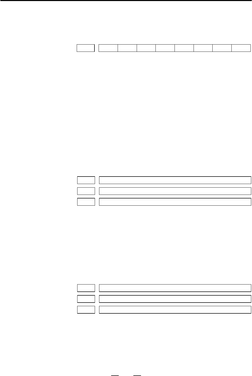
#7
15570
#6 #5 #4 #3
APE
#2
HS3
#1
HS2
#0
HS1
[Data type] Bit
HS1 Interrupts with the first manual pulse generator are:
0 : Not used for tracing control by manual pulse interrupts.
1 : Used for tracing control by manual pulse interrupts.
HS2 Interrupts with the second manual pulse generator are:
0 : Not used for tracing control by manual pulse interrupts.
1 : Used for tracing control by manual pulse interrupts.
HS3 Interrupts with the third manual pulse generator are:
0 : Not used for tracing control by manual pulse interrupts.
1 : Used for tracing control by manual pulse interrupts.
APE The acceleration control function of tracing control by manual pulse
interrupts is:
0 : Enabled only during approach operation. After the approach
operation is completed, the function does not work.
1 : Always enabled during execution.
15572 Approach completion detection width 1
15573 Approach completion detection width 2
15574 Approach completion detection width 3
[Data type] Word
[Unit of data] 0.001 mm
[Valid data range] 0 to 32767
Specify distances along axes 1 and 2 controlled under tracing control by
manual pulse interrupts. Completion of approach is determined by the
specified distances. When a move command by manual pulse interrupt
input maintains the setting or a shorter distance for at least the approach
completion interval time, manual pulse tracing control mode is entered on
the assumption that approach is completed.
15575 Approach completion interval time 1
15576 Approach completion interval time 2
15577 Approach completion interval time 3
[Data type] Word
[Unit of data] msec
[Valid data range] 0 to 32767
If the approach completion detection width or a shorter distance is
maintained for the set time or longer in tracing control by manual pulse
interrupts, approach completion is assumed.
4.25
TRACING CONTROL
BY MANUAL PULSE
INTERRUPTS
Contents Summary of Series 16i/160i-LB Parameter manual
- Page 1PARAMETER MANUAL B-63670EN/01
- Page 2Ȧ No part of this manual may be reproduced in any form. Ȧ All specifications and designs are subject to change without notice. The export of this product is subject to the authorization of the government of the country from where the product is exported. In this manual we have tried as much as possi
- Page 3B–63670EN/01 PREFACE PREFACE Applicable Models The mode covered by this manual, and their abbreviations are : Product Name Abbreviations FANUC Series 16i–LB 16i–LB FANUC Series 160i–LB 160i–LB Manuals related to The table below lists manuals related to Series 16i–LB and 160i–LB. In FANUC Series the
- Page 4PREFACE B–63670EN/01 Manuals related to FANUC SERVO MOTOR α Table 1(b) Manuals Related to the SERVO MOTOR α series series Specification Manual name number FANUC AC SERVO MOTOR α series DESCRIPTIONS B–65142E FANUC AC SERVO MOTOR α series B–65150E PARAMETER MANUAL FANUC SERVO AMPLIFIER α series DESCRI
- Page 5B–63670EN/01 Table of Contents PREFACE . . . . . . . . . . . . . . . . . . . . . . . . . . . . . . . . . . . . . . . . . . . . . . . . . . . . . . . . . . . . . . . . p–1 1. DISPLAYING PARAMETERS . . . . . . . . . . . . . . . . . . . . . . . . . . . . . . . . . . . . . . . . . . . . 1 2. SETTING PAR
- Page 6Table of Contents B–63670EN/01 4.33 STEP FEED FUNCTION AND RETURN FUNCTION . . . . . . . . . . . . . . . . . . . . . . . . . . . . . . . . . . 77 4.34 PARAMETERS RELATED TO GAS PRESSURE CONTROL (2) . . . . . . . . . . . . . . . . . . . . . . . . . 78 c–2
- Page 7B–63670EN/01 1. DISPLAYING PARAMETERS 1 DISPLAYING PARAMETERS Follow the procedure below to display parameters. (1) Press the
function key on the MDI as many times as required, or alternatively, press the function key once, then the [PARAM] section display soft key. The parameter s - Page 82. SETTING PARAMETERS FROM MDI B–63670EN/01 2 SETTING PARAMETERS FROM MDI Follow the procedure below to set parameters. (1) Place the CNC in the MDI mode or the emergency stop state. (2) Follow the substeps below to enable writing of parameters. 1. To display the setting screen, press the
- Page 9B–63670EN/01 2. SETTING PARAMETERS FROM MDI [Example] 12000 [INPUT] PARAMETER (FEEDRATE) O0001 N00010 1401 RDR JZR RPD Cursor 0 0 0 0 0 0 0 0 1402 JRV 0 0 0 0 0 0 0 0 1410 DRY RUN FEEDRATE 12000 1412 0 1420 RAPID FEEDRATE X 15000 Y 15000 Z 15000 > MDI STOP *** *** ALM 10:03:10 [NO.SRH] [ ON:1 ] [ OF
- Page 103. INPUTTING AND OUTPUTTING PARAMETERS THROUGH THE READER/PUNCHER INTERFACE B–63670EN/01 INPUTTING AND OUTPUTTING PARAMETERS THROUGH THE 3 READER/PUNCHER INTERFACE This section explains the parameter input/output procedures for input/output devices connected to the reader/puncher interface. The foll
- Page 113. INPUTTING AND OUTPUTTING PARAMETERS THROUGH B–63670EN/01 THE READER/PUNCHER INTERFACE 3.1 (1) Select the EDIT mode or set to Emergency stop. OUTPUTTING (2) To select the parameter screen, press the
function key as PARAMETERS many times as required, or alternatively press the THR - Page 123. INPUTTING AND OUTPUTTING PARAMETERS THROUGH THE READER/PUNCHER INTERFACE B–63670EN/01 3.2 (1) Place the CNC in the emergency stop state. INPUTTING (2) Enable parameter writing. PARAMETERS 1. To display the setting screen, press the
THROUGH THE function key as many times as requir - Page 13B–63670EN/01 4. DESCRIPTION OF PARAMETERS 4 DESCRIPTION OF PARAMETERS Parameters are classified by data type as follows: Table 4 Data Types and Valid Data Ranges of Parameters Data type Valid data range Remarks Bit 0 or 1 Bit axis Byte 0 to 255 In some parameters, signs are Byte axis –128 to 127 ign
- Page 144. DESCRIPTION OF PARAMETERS B–63670EN/01 4.1 SETTINGS FOR ENABLING/DISABLIN #7 #6 #5 #4 #3 #2 #1 #0 G FUNCTIONS 15000 FLT CLB BMO AGA LGC LPC [Data type] Bit LPC Power control is: 0 : Disabled. (Normal operation) 1 : Enabled. LGC The in–tube pressure control gain selection of two types is: 0 : Disa
- Page 15B–63670EN/01 4. DESCRIPTION OF PARAMETERS #7 #6 #5 #4 #3 #2 #1 #0 15002 PSH PCG ADC BMA [Data type] Bit BMA When the shutter is closed in automatic operation, beam output is: 0 : Disabled. (Normal operation) 1 : Enabled. (Maintenance) ADC AD conversion–2 data is judged with: 0 : The select signal. 1
- Page 164. DESCRIPTION OF PARAMETERS B–63670EN/01 ECH Upon reset, the active E number is: 0 : Not cleared. 1 : Cleared. CWY The oscillator of the: 0 : CO2 laser is used. 1 : CW–YAG laser is used. #7 #6 #5 #4 #3 #2 #1 #0 15005 DLY ITR GNS BPV TTD INB [Data type] Bit INB Beam output is stopped: 0 : Upon the c
- Page 17B–63670EN/01 4. DESCRIPTION OF PARAMETERS #7 #6 #5 #4 #3 #2 #1 #0 15007 STO XSC ECK ESE ESE If piercing is to be executed in edge machining, it is: 0 : Executed upon the completion of distribution. 1 : Executed after a smoothing error check is performed upon the completion of distribution. ECK In ed
- Page 184. DESCRIPTION OF PARAMETERS B–63670EN/01 #7 #6 #5 #4 #3 #2 #1 #0 15009 TEM BCG BEM AFZ BS2 BS1 AS2 AS1 [Data type] Bit These parameters are related to the laser gas mixture function, which store and monitor the operating states of the mixer. The parameters are automatically set and need not be set
- Page 19B–63670EN/01 4. DESCRIPTION OF PARAMETERS #7 #6 #5 #4 #3 #2 #1 #0 15011 OPV ST2 CSC LVE EDS [Data type] Bit EDS The cutting conditions to be assumed during the execution for the return distance in edge machining and start–up machining are: 0 : The same as usual. 1 : Not the same as usual. For the la
- Page 204. DESCRIPTION OF PARAMETERS B–63670EN/01 4.2 DISCHARGE TUBE #7 #6 #5 #4 #3 #2 #1 #0 SELECTION 15025 PS8 PS7 PS6 PS5 PS4 PS3 PS2 PS1 15026 PS16 PS15 PS14 PS13 PS12 PS11 PS10 PS9 [Data type] Bit PS1 to PS16 Discharge tube selection when half of the discharge tubes are used Four of eight discharge tub
- Page 21B–63670EN/01 4. DESCRIPTION OF PARAMETERS 4.3 CONTOURING CONDITIONS 15040 Output power [Data type] Word [Unit of data] W [Valid data range] 0 to 7000 15041 Pulse frequency [Data type] Word [Unit of data] Hz [Valid data range] 5 to 2000 15042 Pulse duty ratio [Data type] Word [Unit of data] % [Valid
- Page 224. DESCRIPTION OF PARAMETERS B–63670EN/01 4.4 EDGE MACHINING 15050 Edge detection angle CONDITIONS [Data type] Word [Unit of data] Degree [Valid data range] 0 to 180 When an angle formed by two blocks is smaller than this setting, the portion is assumed to be a corner. 15051 Piercing peak power [Dat
- Page 23B–63670EN/01 4. DESCRIPTION OF PARAMETERS 15057 Return distance [Data type] Two–word [Unit of data] Increment system Unit IS–A IS–B IS–C Metric input mm 0.01 0.001 0.0001 Inch input inch 0.001 0.0001 0.00001 [Valid data range] 0 to 65000 Specify the return distance of movement from the vertex of a c
- Page 244. DESCRIPTION OF PARAMETERS B–63670EN/01 4.5 PIERCING CONDITIONS 15080 Piercing power [Data type] Word [Unit of data] W [Valid data range] 0 to 7000 Specify a piercing power. 15081 Initial frequency of piercing [Data type] Word [Unit of data] Hz [Valid data range] 5 to 2000 Specify the initial freq
- Page 25B–63670EN/01 4. DESCRIPTION OF PARAMETERS 15086 Piercing step count [Data type] Word [Unit of data] [Valid data range] 0 to 32767 Specify the number of piercing steps. 15087 Piercing end time [Data type] Two–word [Unit of data] Millisecond [Valid data range] 0 to 99999999 Specify a piercing end time
- Page 264. DESCRIPTION OF PARAMETERS B–63670EN/01 4.6 POWER CONTROL #7 #6 #5 #4 #3 #2 #1 #0 15089 LP8 LP7 LP6 LP5 LP4 LPZ LPY LPX [Data type] Bit LP* The speed calculation of the power control function: 0 : Does not use the * axis. 1 : Uses the * axis. When nothing is specified, the system assumes that the
- Page 27B–63670EN/01 4. DESCRIPTION OF PARAMETERS This parameter specifies the width of allowable variation in power control speed. This parameter is effective when parameter No. 15450 is 0. To set a value equal to or greater than 256, use parameter No. 15450. Depending on the setting of the bit 6 (SDB) of
- Page 284. DESCRIPTION OF PARAMETERS B–63670EN/01 15097 Reference value for calculating the output inclination (output when feedrate F is 0) [Data type] Word [Unit of data] W [Valid data range] 0 to 7000 15098 Reference value for calculating the frequency inclination (frequency when feedrate F is 0) [Data t
- Page 29B–63670EN/01 4. DESCRIPTION OF PARAMETERS 4.7 SETTINGS RELATED TO ASSIST GAS PRESSURE AND TIME 15100 Assist gas selection [Data type] Word [Unit of data] [Valid data range] 0 to 7 (when bit 0 of parameter No. 15001 is set to 1) 0 to 3 (when bit 0 of parameter No. 15001 is set to 0) Specify an assist
- Page 304. DESCRIPTION OF PARAMETERS B–63670EN/01 15114 Pre–flow pressure 1 15115 Pre–flow pressure 2 15116 Pre–flow pressure 3 [Data type] Word [Unit of data] 0.01 MPa or 0.1 kg/cm2 [Valid data range] 0 to 255 Specify the pre–flow pressure of the assist gas. 15120 Machining flow pressure 1 15121 Machining
- Page 31B–63670EN/01 4. DESCRIPTION OF PARAMETERS 15136 Assist gas pressure [Data type] Word [Unit of data] 0.01 MPa or 0.1 kg/cm2 [Valid data range] 0 to 255 Specify an assist gas pressure. 15137 Stabilization time of the assist gas pressure for piercing [Data type] Word [Unit of data] 10 milliseconds [Val
- Page 324. DESCRIPTION OF PARAMETERS B–63670EN/01 4.8 LASER MAINTENANCE/ INSPECTION TIME DISPLAY FUNCTION 15150 Laser RUN–ON period [Data type] Two–word [Unit of data] 0.1 hour [Valid data range] 0 to 99999999 The total RUN–ON time is automatically specified. 15151 Vacuum pump operation period [Data type] T
- Page 33B–63670EN/01 4. DESCRIPTION OF PARAMETERS #7 #6 #5 #4 #3 #2 #1 #0 15160 MDS MNT [Data type] Bit MNT The laser maintenance screen is: 0 : Not displayed. 1 : Displayed. Even if the screen is not displayed, the storage of compensation coefficients and the totaling of operation time are performed, so th
- Page 344. DESCRIPTION OF PARAMETERS B–63670EN/01 4.9 PARAMETERS RELATED TO OSCILLATOR CONTROL 15200 Power specified for power calibration when half of the discharge tubes are used [Data type] Word [Unit of data] W [Valid data range] 0 to 32767 Specify the power to be specified to obtain a power calibration
- Page 35B–63670EN/01 4. DESCRIPTION OF PARAMETERS 15206 Time constant of power sensor input filter [Data type] Word [Unit of data] Millisecond [Valid data range] 8 to 32767 The time constant is used when the primary delay filter is applied to the laser power monitor value input from the power sensor. 15207
- Page 364. DESCRIPTION OF PARAMETERS B–63670EN/01 15212 Upper limit on power when the duty ratio is not clamped [Data type] Word [Unit of data] W [Valid data range] 0 to 32767 When the duty ratio is not clamped to 50% according to parameter No. 15213 and when the specified power exceeds this setting after p
- Page 37B–63670EN/01 4. DESCRIPTION OF PARAMETERS 15217 Beam stop delay time [Data type] Word [Unit of data] Millisecond [Valid data range] 0 to 32767 Specify the period from when an in–position check is completed until the beam stops. 15218 Power for clamping the duty ratio of the CW–YAG laser [Data type]
- Page 384. DESCRIPTION OF PARAMETERS B–63670EN/01 4.10 PARAMETERS RELATED TO 15220 Maximum specifiable bias value at the start of discharge DISCHARGE [Data type] Word [Unit of data] mV [Valid data range] 0 to 32767 Specify the maximum bias value that can be specified at the start of discharge. 15221 Dischar
- Page 39B–63670EN/01 4. DESCRIPTION OF PARAMETERS 15230 Value for determining stop of power feedback control [Data type] Word [Unit of data] W [Valid data range] 0 to 32767 If the difference in specified power value between the current block and previous block during automatic operation is the setting in th
- Page 404. DESCRIPTION OF PARAMETERS B–63670EN/01 4.11 PARAMETERS RELATED TO GAS PRESSURE CONTROL (1) 15240 Negative pressure for completing evacuation [Data type] Word [Unit of data] (1=13 Pa) [Valid data range] 0 to 32767 The negative pressure is applied to evacuate the discharge tube during the laser sta
- Page 41B–63670EN/01 4. DESCRIPTION OF PARAMETERS 15245 In–tube pressure control gain 2 [Data type] Word [Unit of data] [Valid data range] 0 to 32767 Specify a gas pressure control gain for reference discharge. This setting is valid when bit 1 (LGC) of parameter No. 15000 is set to 1. 15246 Pressure control
- Page 424. DESCRIPTION OF PARAMETERS B–63670EN/01 15255 Evacuation time at RUN start [Data type] Word [Unit of data] Second [Valid data range] 0 to 32767 Specify an evacuation time at RUN start. 15256 RUN–OFF evacuation time [Data type] Word [Unit of data] Second [Valid data range] 600 to 32767 When bit 2 (
- Page 43B–63670EN/01 4. DESCRIPTION OF PARAMETERS 4.12 HIGHLY REFLECTIVE MATERIAL ALARMS 15265 Maximum permissible output increase [Data type] Word [Unit of data] W [Valid data range] 0 to 32767 When the difference between the specified power and actual power exceeds this value, an alarm 4068 (beam reflecti
- Page 444. DESCRIPTION OF PARAMETERS B–63670EN/01 4.13 LASER POWER/VOLTAGE DECREASE 15270 Normal discharge tube voltage [Data type] Word [Unit of data] V [Valid data range] 0 to 32767 Specify a discharge tube voltage in normal reference discharge. This parameter is automatically rewritten after the discharg
- Page 45B–63670EN/01 4. DESCRIPTION OF PARAMETERS 4.14 POWER TABLE SETTINGS 15280 Power table interval when half of the discharge tubes are used 15281 Power table interval when all of the discharge tubes are used [Data type] Word [Unit of data] [Valid data range] 0 to 32767 [Standard setting] Refer to the a
- Page 464. DESCRIPTION OF PARAMETERS B–63670EN/01 15300 Value 0 when all of the discharge tubes are used 15301 Value 1 when all of the discharge tubes are used 15302 Value 2 when all of the discharge tubes are used 15303 Value 3 when all of the discharge tubes are used 15304 Value 4 when all of the discharg
- Page 47B–63670EN/01 4. DESCRIPTION OF PARAMETERS 4.15 AUTOMATIC AGING FUNCTION 15320 Laser power in normal calibration [Data type] Word [Unit of data] W [Valid data range] 0 to 7000 15321 Oscillation frequency in normal calibration [Data type] Word [Unit of data] Hz [Valid data range] 5 to 2000 15322 Pulse
- Page 484. DESCRIPTION OF PARAMETERS B–63670EN/01 15327 Oscillation frequency in aging [Data type] Word [Unit of data] Hz [Valid data range] 5 to 2000 15328 Pulse duty ratio in aging [Data type] Word [Unit of data] % [Valid data range] 0 to 100 15329 Calibration time in aging [Data type] Word [Unit of data]
- Page 49B–63670EN/01 4. DESCRIPTION OF PARAMETERS 15334 Aging count [Data type] Word [Unit of data] [Valid data range] 0 to 32767 (automatically specified by the CNC) 15335 Time data 1 at HVOFF after LSTR [Data type] Double word [Unit of data] [Valid data range] 0 to 99999999 (automatically specified by the
- Page 504. DESCRIPTION OF PARAMETERS B–63670EN/01 4.16 PARAMETERS RELATED TO THE PMC–WINDOW 15350 M code for reading a comment [Data type] Word [Unit of data] [Valid data range] 0 to 999 Specify an M code for reading the comment of function code 140. 15360 Start address of the R area of the PMC [Data type]
- Page 51B–63670EN/01 4. DESCRIPTION OF PARAMETERS 4.17 POWER CONTROL (2) 15450 Allowable variation in power control speed [Data type] Word [Unit of data] mm/min [Valid data range] 0 to 32767 [Standard setting] 4 Specify the allowable variation in power control speed. If this parameter is 0, parameter No. 15
- Page 524. DESCRIPTION OF PARAMETERS B–63670EN/01 4.18 SETTINGS RELATED TO TRACING 15500 Detection gain coefficient (DETECTION) [Data type] Word [Unit of data] [Valid data range] 0 to 32767 Specify the gain coefficient of the displacement detector in Z–axis tracing control. NOTE This parameter can be set on
- Page 53B–63670EN/01 4. DESCRIPTION OF PARAMETERS 4.19 SETTING RELATED TO TRACING (DISPLAY) #7 #6 #5 #4 #3 #2 #1 #0 15505 TAC TRS TRA EBS [Data type] Bit EBS The process of establishing the tracing displacement amount standard: 0 : Is of the conventional type. (Data is processed one word at a time.) 1 : Can
- Page 544. DESCRIPTION OF PARAMETERS B–63670EN/01 4.20 SETTINGS RELATED TO TRACING (INTEGRATION) 15510 Integral time constant [Data type] Word [Unit of data] Millisecond [Valid data range] 0 to 32767 [Standard setting] 0 The integral time constant is used for displacement integration in Z–axis tracing contr
- Page 55B–63670EN/01 4. DESCRIPTION OF PARAMETERS 4.21 SETTINGS RELATED TO TRACING (PHASE COMPENSATION) 15520 Phase compensation time constant [Data type] Word [Unit of data] Millisecond [Valid data range] 0 to 32767 [Standard setting] 0 (A value lower than 2 is invalid.) This setting is the time constant f
- Page 564. DESCRIPTION OF PARAMETERS B–63670EN/01 4.22 SETTINGS RELATED TO TRACING (DISPLACEMENT) 15530 Reference displacement [Data type] Word [Unit of data] 0.001 mm [Valid data range] Parameter No. 15531 to parameter No. 15532 The setting determines the reference distance from the tip of the quill to the
- Page 57B–63670EN/01 4. DESCRIPTION OF PARAMETERS 15535 Lower limit on gap [Data type] Word [Unit of data] 0.001 mm [Valid data range] 0 to 32767 Specify the minimum value that can be specified for the gap in tracing control. 15536 Upper limit on gap [Data type] Word [Unit of data] 0.001 mm [Valid data rang
- Page 584. DESCRIPTION OF PARAMETERS B–63670EN/01 4.23 SETTINGS RELATED TO TRACING (VELOCITY 15540 Velocity control voltage conversion factor of Z–axis tracing control COMMAND) 15541 Velocity control voltage conversion factor of W–axis tracing control [Data type] Word [Unit of data] [Valid data range] 0 to
- Page 59B–63670EN/01 4. DESCRIPTION OF PARAMETERS 4.24 SETTINGS RELATED TO TRACING (APPROACH) 15550 Approach completion detection range [Data type] Word [Unit of data] 0.001 mm [Valid data range] 0 to 32767 [Standard setting] 50 This setting is the displacement at which the completion of approach is assumed
- Page 604. DESCRIPTION OF PARAMETERS B–63670EN/01 15554 Constant for clamping Z–axis tracing speed [Data type] Word [Unit of data] [Valid data range] 0 to 32767 The setting is used as the constant for clamping the tracing speed. Specify the value obtained using the following expression: Tracing speed clamp
- Page 61B–63670EN/01 4. DESCRIPTION OF PARAMETERS 4.25 TRACING CONTROL BY MANUAL PULSE INTERRUPTS #7 #6 #5 #4 #3 #2 #1 #0 15570 APE HS3 HS2 HS1 [Data type] Bit HS1 Interrupts with the first manual pulse generator are: 0 : Not used for tracing control by manual pulse interrupts. 1 : Used for tracing control
- Page 624. DESCRIPTION OF PARAMETERS B–63670EN/01 15578 Allowable speed increase in tracing control by manual pulse interrupts 1 15579 Allowable speed increase in tracing control by manual pulse interrupts 2 15580 Allowable speed increase in tracing control by manual pulse interrupts 3 [Data type] 2–word [U
- Page 63B–63670EN/01 4. DESCRIPTION OF PARAMETERS 4.26 SETTINGS RELATED TO THREE– DIMENSIONAL AXIAL MOVEMENT #7 #6 #5 #4 #3 #2 #1 #0 15600 TDA NFX NCT RNC MIA NPC [Data type] Bit NPC During a stroke check before movement, movement in the G31 block is: 0 : Checked. 1 : Not checked. MIA During attitude contro
- Page 644. DESCRIPTION OF PARAMETERS B–63670EN/01 #7 #6 #5 #4 #3 #2 #1 #0 15601 OFC RAT PCK RDC RFD PA5 PA4 [Data type] Bit PA4 The rotation around the fourth axis is: 0 : Counterclockwise. 1 : Clockwise. PA5 The rotation around the fifth axis is: 0 : Counterclockwise. 1 : Clockwise. RFD When only the fourt
- Page 65B–63670EN/01 4. DESCRIPTION OF PARAMETERS #7 #6 #5 #4 #3 #2 #1 #0 15602 FMX ZTC OSL TGC [Data type] Bit TGC For interaction control, the rotation of the α axis is specified in a command: 0 : Using a sign different from that used for the β axis rotation command. 1 : Using the same sign as that used f
- Page 664. DESCRIPTION OF PARAMETERS B–63670EN/01 15615 Length of the first arm 15616 Length of the second arm [Data type] Two–word [Unit of data] Increment system Unit IS–A IS–B IS–C Millimeter machine mm 0.01 0.001 0.0001 Inch machine inch 0.001 0.0001 0.00001 [Valid data range] 0 to 500000 (Millimeter ma
- Page 67B–63670EN/01 4. DESCRIPTION OF PARAMETERS 15619 Nozzle length [Data type] Two–word [Unit of data] Increment system Unit IS–A IS–B IS–C Millimeter machine mm 0.01 0.001 0.0001 Inch machine inch 0.001 0.0001 0.00001 [Valid data range] Parameter No. 15616 + parameter No. 15619 x 500000 (Millimeter mach
- Page 684. DESCRIPTION OF PARAMETERS B–63670EN/01 Angle at which rotation is assumed to be only plane rotation in three–dimensional 15623 conversion [Data type] Two–word [Unit of data] 0.001 deg [Valid data range] 0 to 89999 If, in three–dimensional conversion, the difference between the inclination of the
- Page 69B–63670EN/01 4. DESCRIPTION OF PARAMETERS 4.27 PROGRAM RESUMPTION/NEIGH BORING POINT SEARCH #7 #6 #5 #4 #3 #2 #1 #0 15630 NMT NMC NSC PRT NRE NSR PRZ PRS [Data type] Bit PRS The program resume function of: 0 : The standard type is used. 1 : The laser type is used. PRZ While the program resume functi
- Page 704. DESCRIPTION OF PARAMETERS B–63670EN/01 15635 Neighboring point distance of neighboring point search [Data type] Two–word [Unit of data] Increment system Unit IS–A IS–B IS–C Metric input mm 0.01 0.001 0.0001 Inch input inch 0.001 0.0001 0.00001 [Valid data range] 0 to 99999999 Specify the neighbor
- Page 71B–63670EN/01 4. DESCRIPTION OF PARAMETERS 4.28 TEACHING BOX 15638 Start address of teaching box DI area 15639 Start address of teaching box DO area [Data type] Word [Unit of data] [Valid data range] 1 to 999 The DI/DO area can be assigned to a desired address of the internal relay area (R area). Whe
- Page 724. DESCRIPTION OF PARAMETERS B–63670EN/01 15642 Output address of transfer status from TB to extended battery–powered memory [Data type] Word [Unit of data] [Valid data range] 0 to 65528 When an R or S command is specified in the teaching box, the start address, byte count, completion code, and cont
- Page 73B–63670EN/01 4. DESCRIPTION OF PARAMETERS 4.29 SETTINGS RELATED TO MACHINING 15650 Z–axis retraction amount RESUMPTION [Data type] Two–word [Unit of data] Increment system Unit IS–A IS–B IS–C Metric input mm 0.01 0.001 0.0001 Inch input inch 0.001 0.0001 0.00001 [Valid data range] 1 to 99999999 Spec
- Page 744. DESCRIPTION OF PARAMETERS B–63670EN/01 #7 #6 #5 #4 #3 #2 #1 #0 15669 STH N2S [Data type] Bit N2S The piercing conditions for the resumed non–inverted movement are: 0 : As specified in the program. 1 : Determined by the values of parameters Nos. 15670 to 15682. STH In the machining resume function
- Page 75B–63670EN/01 4. DESCRIPTION OF PARAMETERS 15674 Incremental value of piercing duty ratio [Data type] Word [Unit of data] % [Valid data range] 0 to 100 Specify the value by which the duty ratio of piercing is incremented when the machining resume function or a skip is executed. 15675 Piercing step ti
- Page 764. DESCRIPTION OF PARAMETERS B–63670EN/01 15679 Assist gas selection [Data type] Word [Unit of data] [Valid data range] 0 to 7 (when bit 0 of parameter No. 15001 is set to 1) 0 to 3 (when bit 0 of parameter No. 15001 is set to 0) Specify the assist gas type to be selected when the machining resume f
- Page 77B–63670EN/01 4. DESCRIPTION OF PARAMETERS 4.30 CONSTANT OPTICAL PATH CONTROL #7 #6 #5 #4 #3 #2 #1 #0 15700 8 7 6 5 4 z y x [Data type] Bit X to 8 When a move command for the axis of mirror movement is calculated, the corresponding axis is: 0 : Not used. 1 : Used. NOTE Specify 0 for the bit correspon
- Page 784. DESCRIPTION OF PARAMETERS B–63670EN/01 15703 Mirror block axis selection [Data type] Byte [Unit of data] [Valid data range] 4 to 8 Specify the axis number of an axis of mirror movement. The axis must not be the X–axis, Y–axis or Z–axis. 15704 Mirror block axis reference position calibration [Data
- Page 79B–63670EN/01 4. DESCRIPTION OF PARAMETERS 4.31 LASER GAS MIXTURE FUNCTION 15710 Cylinder level check wait time [Data type] Word [Unit of data] Second [Valid data range] 0 to 32767 Specify a wait time for checking the cylinder level. 15711 Gas mixture wait time [Data type] Word [Unit of data] Minute
- Page 804. DESCRIPTION OF PARAMETERS B–63670EN/01 15715 Degree of vacuum of gas pressure [Data type] Word [Unit of data] (1=13 Pa) [Valid data range] 0 to 32767 The degree of vacuum of the laser gas pressure in the gas mixer is measured. When the laser gas pressure is below the setting, an alarm is raised.
- Page 81B–63670EN/01 4. DESCRIPTION OF PARAMETERS 4.32 THE STEP CONTROL FUNCTION 15730 Distance of a single ramp–up step [Data type] Word [Unit of data] Increment system Unit IS–A IS–B IS–C Metric input mm 0.01 0.001 0.0001 Inch input inch 0.001 0.0001 0.00001 [Valid data range] 0 to 65000 Specify the dista
- Page 824. DESCRIPTION OF PARAMETERS B–63670EN/01 15746 Laser power of ramp–down step 1 15747 Laser power of ramp–down step 2 15748 Laser power of ramp–down step 3 15749 Laser power of ramp–down step 4 15750 Laser power of ramp–down step 5 15751 Laser power of ramp–down step 6 15752 Laser power of ramp–down
- Page 83B–63670EN/01 4. DESCRIPTION OF PARAMETERS 4.33 STEP FEED FUNCTION AND RETURN FUNCTION 15770 Feedrate of step feed or return [Data type] Two–word [Unit of data, valid data range] Valid data range Increment system Unit of data IS–A, IS–B IS–C Millimeter machine system 1 mm/min 0 to 240000 0 to 100000
- Page 844. DESCRIPTION OF PARAMETERS B–63670EN/01 4.34 PARAMETERS RELATED TO GAS PRESSURE #7 #6 #5 #4 #3 #2 #1 #0 CONTROL (2) 15800 TPC [Data type] Bit TPC The turbo blower constant–power drive control function is: 0 : Disabled. 1 : Enabled. Maximum in–tube pressure when the turbo blower constant–power driv
- Page 85B–63670EN/01 Index [A] Parameters Related to Gas Pressure Control (1), 34 Parameters Related to Gas Pressure Control (2), 78 Automatic Aging Function, 41 Parameters Related to Oscillator Control, 28 Parameters Related to the PMC–WINDOW, 44 [C] Piercing Conditions, 18 Constant Optical Path Control, 7
- Page 86
- Page 87Revision Record FANUCĄSeriesĄ16i/160i – LB PARAMETER MANUAL (B–63670EN) 01 Mar., 2002 Edition Date Contents Edition Date Contents
- Page 88