Series 30i/300i/300is - Model A Descriptions Page 220
Descriptions
5.PROGRAM INPUT NC FUNCTION B-63942EN/02
- 190 -
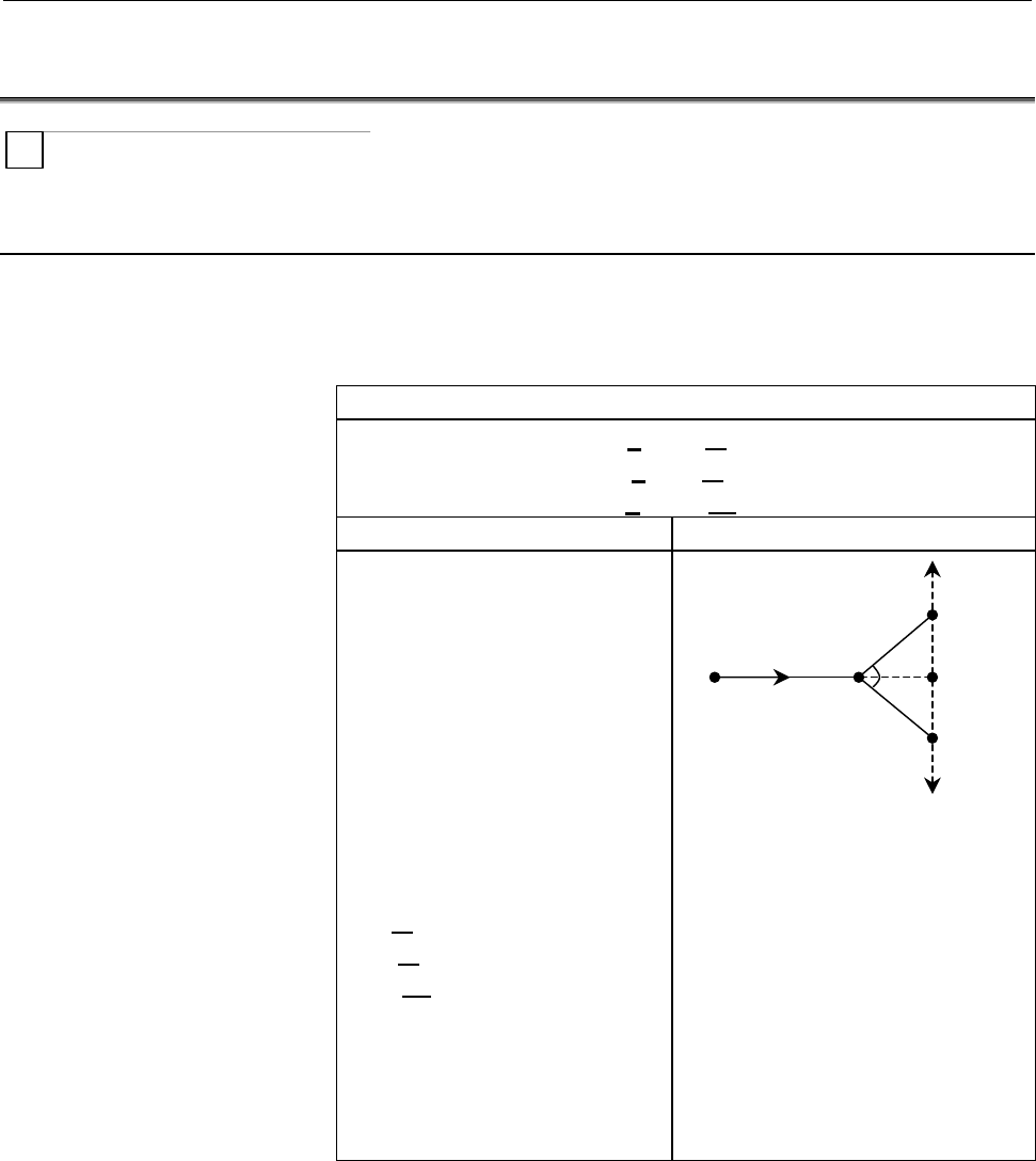
5.26 CHAMFERING AND CORNER R
T
A chamfer or corner R are can be inserted between two blocks which
intersect at a right angle as follows.
Format
- Chamfering
Plane selection 1st axis → Plane selection 2nd axis
(G17 plane : X
P
→ Y
P
, G18 plane : Z
P
→ X
P
, G19 plane : Y
P
→ Z
P
)
Format
G17 plane : G01 X
P
(U) J(C)±j ;
G18 plane : G01 Z
P
(W) I(C)±i ;
G19 plane : G01 Y
P
(V) K(C)±k ;
Description of symbols Tool movement
X
P
(U)_
Y
P
(V)_
Z
P
(W)_
I(C)±i
J(C)±j
K(C)±k
Specifies movement from
point a to point b with an
absolute or incremental
programming in the figure
on the right.
X
P
is the X-axis (basic
axis) or its parallel axis,
Y
P
is the Y-axis (basic
axis) or its parallel axis,
and Z
P
is the Z-axis
(basic axis) or its parallel
axis.
Specify the distance
between points b and c
in the right-hand figure
with address J, J, K, or
C followed by a sign.
(When bit 4 (CCR) of
parameter No. 3405 is
set to 0, use I, J, or K.
When the bit is set to1,
use C.)
Movements are made from a to d
to c.
(In the plane selection 2nd axis +
direction if the I, J, K, or C
command specifies +, or in the
plane selection 2nd axis - direction
if I, J, K, or C command specifies -)
a
Start
point
d
)
c
c
b
)
i,j,k
i,j,k
45°
45°
Plane selection 2nd axis +
direction
Plane selection 2nd
axis - direction
Contents Summary of Series 30i/300i/300is - Model A Descriptions
- Page 1FANUC Series 30*/300*/300*s-MODEL A FANUC Series 31*/310*/310*s-MODEL A5 FANUC Series 31*/310*/310*s-MODEL A FANUC Series 32*/320*/320*s-MODEL A DESCRIPTIONS B-63942EN/02
- Page 2• No part of this manual may be reproduced in any form. • All specifications and designs are subject to change without notice. The export of this product is subject to the authorization of the government of the country from where the product is exported. In this manual we have tried as much as possi
- Page 3B-63942EN/02 SAFETY PRECAUTIONS SAFETY PRECAUTIONS This section describes the safety precautions related to the use of CNC units. It is essential that these precautions be observed by users to ensure the safe operation of machines equipped with a CNC unit (all descriptions in this section assume thi
- Page 4SAFETY PRECAUTIONS B-63942EN/02 1.1 DEFINITION OF WARNING, CAUTION, AND NOTE This manual includes safety precautions for protecting the user and preventing damage to the machine. Precautions are classified into Warning and Caution according to their bearing on safety. Also, supplementary information
- Page 5B-63942EN/02 SAFETY PRECAUTIONS 1.2 GENERAL WARNINGS AND CAUTIONS WARNING 1 Never attempt to machine a workpiece without first checking the operation of the machine. Before starting a production run, ensure that the machine is operating correctly by performing a trial run using, for example, the sin
- Page 6SAFETY PRECAUTIONS B-63942EN/02 WARNING 5 The parameters for the CNC and PMC are factory-set. Usually, there is not need to change them. When, however, there is not alternative other than to change a parameter, ensure that you fully understand the function of the parameter before making any change.
- Page 7B-63942EN/02 SAFETY PRECAUTIONS NOTE Programs, parameters, and macro variables are stored in nonvolatile memory in the CNC unit. Usually, they are retained even if the power is turned off. Such data may be deleted inadvertently, however, or it may prove necessary to delete all data from nonvolatile
- Page 8SAFETY PRECAUTIONS B-63942EN/02 1.3 WARNINGS AND CAUTIONS RELATED TO PROGRAMMING This section covers the major safety precautions related to programming. Before attempting to perform programming, read the supplied User’s Manual carefully such that you are fully familiar with their contents. WARNING
- Page 9B-63942EN/02 SAFETY PRECAUTIONS WARNING 5 Constant surface speed control When an axis subject to constant surface speed control approaches the origin of the workpiece coordinate system, the spindle speed may become excessively high. Therefore, it is necessary to specify a maximum allowable speed. Sp
- Page 10SAFETY PRECAUTIONS B-63942EN/02 WARNING 11 Programmable mirror image Note that programmed operations vary considerably when a programmable mirror image is enabled. 12 Compensation function If a command based on the machine coordinate system or a reference position return command is issued in compens
- Page 11B-63942EN/02 SAFETY PRECAUTIONS 1.4 WARNINGS AND CAUTIONS RELATED TO HANDLING This section presents safety precautions related to the handling of machine tools. Before attempting to operate your machine, read the supplied User’s Manual carefully, such that you are fully familiar with their contents.
- Page 12SAFETY PRECAUTIONS B-63942EN/02 WARNING 5 Disabled override If override is disabled (according to the specification in a macro variable) during threading, rigid tapping, or other tapping, the speed cannot be predicted, possibly damaging the tool, the machine itself, the workpiece, or causing injury
- Page 13B-63942EN/02 SAFETY PRECAUTIONS WARNING 10 Manual intervention If manual intervention is performed during programmed operation of the machine, the tool path may vary when the machine is restarted. Before restarting the machine after manual intervention, therefore, confirm the settings of the manual
- Page 14SAFETY PRECAUTIONS B-63942EN/02 1.5 WARNINGS RELATED TO DAILY MAINTENANCE WARNING 1 Memory backup battery replacement When replacing the memory backup batteries, keep the power to the machine (CNC) turned on, and apply an emergency stop to the machine. Because this work is performed with the power o
- Page 15B-63942EN/02 SAFETY PRECAUTIONS WARNING 2 Absolute pulse coder battery replacement When replacing the memory backup batteries, keep the power to the machine (CNC) turned on, and apply an emergency stop to the machine. Because this work is performed with the power on and the cabinet open, only those
- Page 16SAFETY PRECAUTIONS B-63942EN/02 WARNING 3 Fuse replacement Before replacing a blown fuse, however, it is necessary to locate and remove the cause of the blown fuse. For this reason, only those personnel who have received approved safety and maintenance training may perform this work. When replacing
- Page 17B-63942EN/02 TABLE OF CONTENTS TABLE OF CONTENTS SAFETY PRECAUTIONS............................................................................s-1 I. GENERAL 1 GENERAL ............................................................................................... 3 II. NC FUNCTION 1 CONTROLLED AXIS
- Page 18TABLE OF CONTENTS B-63942EN/02 1.22 CHOPPING FUNCTION .............................................................................. 55 1.23 INCREMENT SYSTEM................................................................................ 56 1.24 FLEXIBLE FEED GEAR ...................................
- Page 19B-63942EN/02 TABLE OF CONTENTS 1.49.2 Linear Scale with Absolute Address Reference Mark Expansion..........................72 1.50 LINEAR SCALE WITH DISTANCE-CODED REFERENCE MARKS (SERIAL) ..................................................................................................... 73 1.51 A
- Page 20TABLE OF CONTENTS B-63942EN/02 2.20.2 Tool Axis Right-Angle Direction Handle Feed / Tool Axis Right-Angle Direction Jog Feed / Tool Axis Right-Angle Direction Incremental Feed.............91 2.20.3 Tool Tip Center Rotation Handle Feed / Tool Tip Center Rotation Jog Feed / Tool Tip Center Rotation In
- Page 21B-63942EN/02 TABLE OF CONTENTS 3.22 MULTIPLE THREADING ........................................................................... 121 3.23 THREADING RETRACT............................................................................ 122 3.23.1 Threading Retract (Canned Cycle).......................
- Page 22TABLE OF CONTENTS B-63942EN/02 4.12 BELL-SHAPED ACCELERATION/DECELERATION AFTER CUTTING FEED INTERPOLATION ........................................................................... 151 4.13 LINEAR ACCELERATION/DECELERATION BEFORE CUTTING FEED INTERPOLATION..........................................
- Page 23B-63942EN/02 TABLE OF CONTENTS 5.14 DIAMETER/RADIUS DYNAMIC SWITCHING........................................... 171 5.15 PLANE SELECTION.................................................................................. 172 5.16 ROTARY AXIS SPECIFICATION .............................................
- Page 24TABLE OF CONTENTS B-63942EN/02 5.30 SUB PROGRAM CALL.............................................................................. 207 5.31 CUSTOM MACRO..................................................................................... 209 5.32 ADDITION OF CUSTOM MACRO COMMON VARIABLES ...........
- Page 25B-63942EN/02 TABLE OF CONTENTS 6.2 MANUAL GUIDE i BASIC......................................................................... 261 6.3 MANUAL GUIDE i MILLING CYCLE ........................................................ 261 6.4 MANUAL GUIDE i TURNING CYCLE ........................................
- Page 26TABLE OF CONTENTS B-63942EN/02 8.7 TOOL OFFSET.......................................................................................... 290 8.8 TOOL CENTER POINT CONTROL FOR 5-AXIS MACHINING................. 292 8.9 Y-AXIS OFFSET......................................................................
- Page 27B-63942EN/02 TABLE OF CONTENTS 9.10 STRAIGHTNESS COMPENSATION......................................................... 324 9.11 INTERPOLATION TYPE STRAIGHTNESS COMPENSATION................. 325 9.11.1 Straightness Compensation 128 Points ..............................................................
- Page 28TABLE OF CONTENTS B-63942EN/02 12.14 OPTIONAL PATH NAME DISPLAY........................................................... 352 12.15 OPERATING MONITOR SCREEN............................................................ 353 12.16 SERVO SETTING SCREEN....................................................
- Page 29B-63942EN/02 TABLE OF CONTENTS 13.2 FAST DATA SERVER ............................................................................... 381 13.3 BUFFER MODE OF DATA SERVER ........................................................ 381 13.4 EXTERNAL DATA INPUT..............................................
- Page 30TABLE OF CONTENTS B-63942EN/02 16.1.9 Rewinding Signal .................................................................................................399 16.1.10 Inch Input Signal ..................................................................................................399 16.1.11 Cutting
- Page 31I. GENERA
- Page 32
- Page 33B-63942EN/02 GENERAL 1.GENERAL 1 GENERAL The FANUC Series 30i/31i/32i-MODEL A is the latest AI nano CNC that has been developed as a successor to the FANUC Series 16i/18i/21i. This CNC flexibly supports various machine tools such as automatic machines, lathes, combined machines, 5-axis machines and
- Page 341.GENERAL GENERAL B-63942EN/02 • The FANUC Series 300i/310i/320i are open CNCs that provide personal computer functions compatible with Microsoft Windows 2000/XP, as well as CNC control functions equivalent to those of the Series 30i/31i/32i. The FANUC Series 300is/310is/320is are also available,
- Page 35B-63942EN/02 GENERAL 1.GENERAL Related manuals of Series 30i/300i/300is- MODEL A Series 31i/310i/310is- MODEL A Series 31i/310i/310is- MODEL A5 Series 32i/320i/320is- MODEL A The following table lists the manuals related to Series 30i/300i/300is- A, Series 31i/310i/310is-A, Series 31i/310i/310is-A5,
- Page 361.GENERAL GENERAL B-63942EN/02 Related manuals of SERVO MOTOR αis/αi/βis/βi series The following table lists the manuals related to SERVO MOTOR αis/αi/βis/βi series Table 2 Related manuals Specification Manual name number FANUC AC SERVO MOTOR αis series FANUC AC SERVO MOTOR αi series B-65262EN DESCR
- Page 37B-63942EN/02 GENERAL 1.GENERAL Special symbols This manual uses the following symbols: - M Indicates a description or function that is valid only for the machine center system (M series) set as system control type. The term "M series" used in the text means "machining center system type". - T Indica
- Page 382.LIST OF SPECIFICATION GENERAL B-63942EN/02 2 LIST OF SPECIFICATION A : Standard B : Standard option C : Option D : Function included in another option - : Not Available Note) Some combinations of these options are restricted. M represents a machining center system. T represents a lathe system. For
- Page 39B-63942EN/02 GENERAL 2.LIST OF SPECIFICATION Series 30i-A Series 31i-A5 Series 31i-A Series 32i-A Series 300i-A Series 310i-A5 Series 310i-A Series 320i-A Item Specifications Series 300is-A Series 310is-A5 Series 310is-A Series 320is-A M T M T M T M T Max. 4 axes/8 axes C C - - - - - - Cs contouring
- Page 402.LIST OF SPECIFICATION GENERAL B-63942EN/02 Series 30i-A Series 31i-A5 Series 31i-A Series 32i-A Series 300i-A Series 310i-A5 Series 310i-A Series 320i-A Item Specifications Series 300is-A Series 310is-A5 Series 310is-A Series 320is-A M T M T M T M T Chopping C - C - C - C - Increment system IS-A,
- Page 41B-63942EN/02 GENERAL 2.LIST OF SPECIFICATION Series 30i-A Series 31i-A5 Series 31i-A Series 32i-A Series 300i-A Series 310i-A5 Series 310i-A Series 320i-A Item Specifications Series 300is-A Series 310is-A5 Series 310is-A Series 320is-A M T M T M T M T Linear scale I/F expansion with absolute C C C C
- Page 422.LIST OF SPECIFICATION GENERAL B-63942EN/02 Series 30i-A Series 31i-A5 Series 31i-A Series 32i-A Series 300i-A Series 310i-A5 Series 310i-A Series 320i-A Item Specifications Series 300is-A Series 310is-A5 Series 310is-A Series 320is-A M T M T M T M T FANUC SERVO MOTOR β Series with I/O Link C C C C
- Page 43B-63942EN/02 GENERAL 2.LIST OF SPECIFICATION Series 30i-A Series 31i-A5 Series 31i-A Series 32i-A Series 300i-A Series 310i-A5 Series 310i-A Series 320i-A Item Specifications Series 300is-A Series 310is-A5 Series 310is-A Series 320is-A M T M T M T M T Continuous threading D A D A D A D A Variable le
- Page 442.LIST OF SPECIFICATION GENERAL B-63942EN/02 Series 30i-A Series 31i-A5 Series 31i-A Series 32i-A Series 300i-A Series 310i-A5 Series 310i-A Series 320i-A Item Specifications Series 300is-A Series 310is-A5 Series 310is-A Series 320is-A M T M T M T M T Rapid traverse bell-shaped A A A A A A A A accel
- Page 45B-63942EN/02 GENERAL 2.LIST OF SPECIFICATION Series 30i-A Series 31i-A5 Series 31i-A Series 32i-A Series 300i-A Series 310i-A5 Series 310i-A Series 320i-A Item Specifications Series 300is-A Series 310is-A5 Series 310is-A Series 320is-A M T M T M T M T Horizontal and vertical Parity check A A A A A A
- Page 462.LIST OF SPECIFICATION GENERAL B-63942EN/02 Series 30i-A Series 31i-A5 Series 31i-A Series 32i-A Series 300i-A Series 310i-A5 Series 310i-A Series 320i-A Item Specifications Series 300is-A Series 310is-A5 Series 310is-A Series 320is-A M T M T M T M T Custom macro common variables Only for more than
- Page 47B-63942EN/02 GENERAL 2.LIST OF SPECIFICATION Series 30i-A Series 31i-A5 Series 31i-A Series 32i-A Series 300i-A Series 310i-A5 Series 310i-A Series 320i-A Item Specifications Series 300is-A Series 310is-A5 Series 310is-A Series 320is-A M T M T M T M T Integrated Operation guidance function MANUAL GU
- Page 482.LIST OF SPECIFICATION GENERAL B-63942EN/02 Series 30i-A Series 31i-A5 Series 31i-A Series 32i-A Series 300i-A Series 310i-A5 Series 310i-A Series 320i-A Item Specifications Series 300is-A Series 310is-A5 Series 310is-A Series 320is-A M T M T M T M T Tool function/Tool compensation Tool function T7
- Page 49B-63942EN/02 GENERAL 2.LIST OF SPECIFICATION Series 30i-A Series 31i-A5 Series 31i-A Series 32i-A Series 300i-A Series 310i-A5 Series 310i-A Series 320i-A Item Specifications Series 300is-A Series 310is-A5 Series 310is-A Series 320is-A M T M T M T M T Tool management function for Tool management C C
- Page 502.LIST OF SPECIFICATION GENERAL B-63942EN/02 Series 30i-A Series 31i-A5 Series 31i-A Series 32i-A Series 300i-A Series 310i-A5 Series 310i-A Series 320i-A Item Specifications Series 300is-A Series 310is-A5 Series 310is-A Series 320is-A M T M T M T M T 128points. Interpolation type straightness Store
- Page 51B-63942EN/02 GENERAL 2.LIST OF SPECIFICATION Series 30i-A Series 31i-A5 Series 31i-A Series 32i-A Series 300i-A Series 310i-A5 Series 310i-A Series 320i-A Item Specifications Series 300is-A Series 310is-A5 Series 310is-A Series 320is-A M T M T M T M T Setting and display Status display A A A A A A A
- Page 522.LIST OF SPECIFICATION GENERAL B-63942EN/02 Series 30i-A Series 31i-A5 Series 31i-A Series 32i-A Series 300i-A Series 310i-A5 Series 310i-A Series 320i-A Item Specifications Series 300is-A Series 310is-A5 Series 310is-A Series 320is-A M T M T M T M T English A A A A A A A A Japanese C C C C C C C C
- Page 53B-63942EN/02 GENERAL 2.LIST OF SPECIFICATION Series 30i-A Series 31i-A5 Series 31i-A Series 32i-A Series 300i-A Series 310i-A5 Series 310i-A Series 320i-A Item Specifications Series 300is-A Series 310is-A5 Series 310is-A Series 320is-A M T M T M T M T External tool offset C C C C C C C C External ma
- Page 542.LIST OF SPECIFICATION GENERAL B-63942EN/02 Series 30i-A Series 31i-A5 Series 31i-A Series 32i-A Series 300i-A Series 310i-A5 Series 310i-A Series 320i-A Item Specifications Series 300is-A Series 310is-A5 Series 310is-A Series 320is-A M T M T M T M T Others NC ready, servo ready, automatic operatio
- Page 55B-63942EN/02 GENERAL 2.LIST OF SPECIFICATION Series 30i-A Series 31i-A5 Series 31i-A Series 32i-A Series 300i-A Series 310i-A5 Series 310i-A Series 320i-A Item Specifications Series 300is-A Series 310is-A5 Series 310is-A Series 320is-A M T M T M T M T I/O Link - AS-i converter C C C C C C C C Manula
- Page 562.LIST OF SPECIFICATION GENERAL B-63942EN/02 Software of personal computer part in case of the CNC system which is Series 300i/310i-A5/310i/320i or connected with personal computer via HSSB (High Speed Serial Bus) Items Specifications Remarks ® Operating system Windows 2000/XP (*4) Microsoft Corp. E
- Page 57B-63942EN/02 GENERAL 2.LIST OF SPECIFICATION Hardware of HSSB(High Speed Serial Bus) and Required hardware of commercially available personal computer in case of the CNC system which is connected with the personal computer via HSSB(High Speed Serial Bus). Items Specifications Remarks Option board in
- Page 582.LIST OF SPECIFICATION GENERAL B-63942EN/02 Hardware of Display Unit for is series CNC used in Series 300is/310is- A5/310is/320is Items Specifications Remarks CPU RENESAS SH-4 Main memory 64MBytes or 128MBytes File memory CompactFlash™ card (*4) Built-in 10.4" color TFT LCD (640×480 dots), or 12.1"
- Page 59II. NC FUNCTIO
- Page 60
- Page 61B-63942EN/02 NC FUNCTION 1.CONTROLLED AXIS 1 CONTROLLED AXIS - 31 -
- Page 621.CONTROLLED AXIS NC FUNCTION B-63942EN/02 1.1 NUMBER OF MAXIMUM CONTROLLED AXES The number of maximum controlled axes is the sum of the number of machine controlled axes and the number of loader controlled axes. The number of Cs and PMC axes is included in the number of machine controlled axes. The
- Page 63B-63942EN/02 NC FUNCTION 1.CONTROLLED AXIS 1.3 NUMBER OF CONTROLLED PATHS A path represents a group of axes that are controlled by the same NC program. Up to 10 paths can be used, depending on the type of NC system. (A path for loader control is included as a path.) Which machine group the local pat
- Page 641.CONTROLLED AXIS NC FUNCTION B-63942EN/02 1.4 NUMBER OF CONTROLLED AXES / NUMBER OF CONTROLLED SPINDLE AXES The number of controlled axes and controlled spindle axes depends on the model, as shown below. Series 30i-A Series 31i-A5 Series 31i-A Series 32i-A Item Series 300i-A Series 310i-A5 Series 3
- Page 65B-63942EN/02 NC FUNCTION 1.CONTROLLED AXIS 1.6 AXIS CONTROL BY PMC The PMC can directly control any given axis, independent of the CNC. By specifying an amount of travel, feedrate, and so forth from the PMC, a movement can be made along an axis independently of other axes operated under CNC control.
- Page 661.CONTROLLED AXIS NC FUNCTION B-63942EN/02 1.7 Cs CONTOURING CONTROL The Cs contouring control function positions the serial spindle using the spindle motor in conjunction with a dedicated detector mounted on the spindle. The Cs contouring control function is higher in precision than spindle positio
- Page 67B-63942EN/02 NC FUNCTION 1.CONTROLLED AXIS 1.9 NAMES OF AXES 1.9.1 Names of Axes Axis names can be assigned to axes controlled by the CNC (including PMC controlled axes). An axis name can be freely selected from 'A', 'B', 'C', 'U', 'V', 'W', 'X', 'Y', and 'Z'. NOTE 1 The same name must not be set fo
- Page 681.CONTROLLED AXIS NC FUNCTION B-63942EN/02 1.9.2 Axis Name Expansion The axis name expansion function enables an axis name to be extended by up to three characters. In order to extend an axis name: (1) Enable the parameter for the axis name expansion function. (2) Set the first character ('A', 'B',
- Page 69B-63942EN/02 NC FUNCTION 1.CONTROLLED AXIS 1.10 ARBITRARY AXIS NAME SETTING When the custom macro function is enabled, an indirect command based on an axis number can be specified for an axis address by using AX[(Axis number)], instead of direct axis name specification. By using AXNUM[(Axis name)],
- Page 701.CONTROLLED AXIS NC FUNCTION B-63942EN/02 1.10.2 AXNUM Function By using AXNUM[ ], an axis number can be obtained. Format AXNUM[ (Axis name) ]; Explanation If an invalid (Axis name) is specified, an alarm is issued. Example) Suppose that there are three controlled axes and that the first axis name
- Page 71B-63942EN/02 NC FUNCTION 1.CONTROLLED AXIS 1.11 SPINDLE NAME EXPANSION A spindle name can be extended by up to three characters starting with 'S' as the first spindle name. With this function, a command can be specified for each spindle without specifying a P command. As the second and third spindle
- Page 721.CONTROLLED AXIS NC FUNCTION B-63942EN/02 1.12 SYNCHRONOUS / MIXTURE CONTROL In multi-path control, movements are usually made on the axes of a path according to a move command for the path (independent control in each path). However, the synchronous/mixture control function enables an arbitrary ax
- Page 73B-63942EN/02 NC FUNCTION 1.CONTROLLED AXIS CAUTION 1 Synchronization mentioned above means that a move command for the master axis is also specified for a slave axis at the same time. Synchronization loss compensation, which detects the positional deviation between the master axis and slave axis and
- Page 741.CONTROLLED AXIS NC FUNCTION B-63942EN/02 - Mixture control A move command for an arbitrary axis of one path and a move command for an arbitrary axis of another path can be exchanged with each other to make a movement on each axis. Example) A move command for the X1 axis of path 1 and a command for
- Page 75B-63942EN/02 NC FUNCTION 1.CONTROLLED AXIS 1.13 SUPERIMPOSED CONTROL In multi-path control, usually, movements are made on the axes of path 1 according to a move command for path 1, and movements are made on the axes of path 2 according to a move command for path 2 (independent control in each path)
- Page 761.CONTROLLED AXIS NC FUNCTION B-63942EN/02 - Superimposed Control To the travel distance on an axis (slave axis) for which an ordinary move command is executed, the travel distance on the axis (master axis) of another path is added. Superimposed control resembles synchronous control. In superimposed
- Page 77B-63942EN/02 NC FUNCTION 1.CONTROLLED AXIS 1.14 AXIS SYNCHRONOUS CONTROL When a movement is made along one axis by using two servo motors as in the case of a large gantry machine, a command for one axis can drive the two motors by synchronizing one motor with the other. Moreover, by using a feedback
- Page 781.CONTROLLED AXIS NC FUNCTION B-63942EN/02 1.15 ANGULAR AXIS CONTROL When the angular axis installed makes an angle other than 90° with the perpendicular axis, the angular axis control function controls the distance traveled along each axis according to the inclination angle as in the case where the
- Page 79B-63942EN/02 NC FUNCTION 1.CONTROLLED AXIS 1.16 INCLINED ROTARY AXIS CONTROL The conventional tilted working plane command / tool center point control function for 5-axis machining / cutter compensation for 5-axis machining / manual handle feed for 5-axis machining are used only for those machines w
- Page 801.CONTROLLED AXIS NC FUNCTION B-63942EN/02 The machine shown in following figure has rotary axis B (master) that turns around the Y-axis and rotary axis C (slave) whose Y-axis is inclined at an angle of 45 degrees on the Y-Z plane. The tilted working plane command / tool center point control functio
- Page 81B-63942EN/02 NC FUNCTION 1.CONTROLLED AXIS The machine shown in following figure has tool rotation axis B whose Y-axis is inclined at an angle of 45 degrees on the Y-Z plane and table rotation axis C that turns around the Z-axis. The tilted working plane command / tool center point control function
- Page 821.CONTROLLED AXIS NC FUNCTION B-63942EN/02 1.17 TANDEM CONTROL If a single motor cannot produce sufficient torque to move a large table, for example, this function allows two motors to be used. By means of this function, two motors can be used to perform movement along a single axis. Positioning is
- Page 83B-63942EN/02 NC FUNCTION 1.CONTROLLED AXIS 1.18 TANDEM DISTURBANCE ELIMINATION CONTROL This function suppresses vibration caused by interference between the main axis and sub-axis in position tandem control (feed axis synchronization). Disturbance Servo NC command + + + + Position Velocity fbm Veloc
- Page 841.CONTROLLED AXIS NC FUNCTION B-63942EN/02 1.19 TORQUE CONTROL For a PMC controlled axis, continuous feed based on torque control is performed. Control on a PMC controlled axis can be switched from position control to torque control, so that the servo motor outputs torque as specified by the NC. 1.2
- Page 85B-63942EN/02 NC FUNCTION 1.CONTROLLED AXIS 1.22 CHOPPING FUNCTION M When contour grinding is performed, the chopping function can be used to grind the side face of a workpiece. By means of this function, while the grinding axis (the axis with the grinding wheel) is being moved vertically, a contour
- Page 861.CONTROLLED AXIS NC FUNCTION B-63942EN/02 1.23 INCREMENT SYSTEM Five types of increment systems are available as indicated in the table below, and can be chosen from by parameter setting. Table 1.23 (a) Increment system Name of Least command Least input increment increment system increment 0.01 mm
- Page 87B-63942EN/02 NC FUNCTION 1.CONTROLLED AXIS 1.24 FLEXIBLE FEED GEAR The detection multiply (DMR) can be extended to set DMR=n/m by using two parameters n and m. 1.25 ARBITRARY COMMAND MULTIPLY When the detection unit assumes a special value, an arbitrary command multiply can be set using the ratio of
- Page 881.CONTROLLED AXIS NC FUNCTION B-63942EN/02 1.27 HRV CONTROL HRV control is a digital servo current control method, and the HRV control system includes servo HRV2, servo HRV3, and servo HRV4. By employing these control methods, even higher speed, higher precision, and higher machining speed can be ac
- Page 89B-63942EN/02 NC FUNCTION 1.CONTROLLED AXIS 1.28 INCH/METRIC CONVERSION Either inch or metric input (least input increment) can be selected by G code. Format G20 ; Inch input G21 ; Metric input Explanation This G code must be specified in an independent block before setting the coordinate system at t
- Page 901.CONTROLLED AXIS NC FUNCTION B-63942EN/02 1.29 INTERLOCK 1.29.1 Start Lock This function disables movement along axes during automatic operation (memory operation, DNC operation, or MDI operation). 1.29.2 All-axis Interlock Feed on all axes can be disabled. If all-axis interlock is applied during m
- Page 91B-63942EN/02 NC FUNCTION 1.CONTROLLED AXIS 1.30 MACHINE LOCK 1.30.1 All-axis Machine Lock The change of the position display can be monitored without moving the machine. When all-axis machine lock signal is set to 1, output pulses (move commands) to the servo motors are stopped in manual or automati
- Page 921.CONTROLLED AXIS NC FUNCTION B-63942EN/02 1.33 STORED STROKE CHECK 1 A machine movable range is set with coordinates in the machine coordinate system in parameters. If the machine attempts to move beyond the range, it is decelerated and stopped and an alarm is displayed. This function is enabled af
- Page 93B-63942EN/02 NC FUNCTION 1.CONTROLLED AXIS 1.35 STORED STROKE CHECK 2 (G22, G23) For stored stroke check 2, the outside or inside of the area specified by parameters or a program is defined as the forbidden area. As a limit position, specify a distance from the origin of the machine coordinate syste
- Page 941.CONTROLLED AXIS NC FUNCTION B-63942EN/02 1.37 STROKE LIMIT CHECK BEFORE MOVE During automatic operation, before the movement specified by a given block is started, whether the tool enters the inhibited area defined by stored stroke check 1, 2, or 3 is checked by determining the coordinate of the e
- Page 95B-63942EN/02 NC FUNCTION 1.CONTROLLED AXIS 1.38 CHUCK AND TAIL STOCK BARRIER T The chuck and tail stock barrier function prevents damage to the machine by checking whether the tool tip interferes with either the chuck or tail stock. Specify an area into which the tool may not enter (entry-prohibitio
- Page 961.CONTROLLED AXIS NC FUNCTION B-63942EN/02 Symbol Description Chuck-shape selection (0: Holding the inner face of a TY tool, 1: Holding the outer face of a tool) CX Chuck position (along X-axis) CZ Chuck position (along Z-axis) L Length of chuck jaws W Depth of chuck jaws (radius) L1 Holding length
- Page 97B-63942EN/02 NC FUNCTION 1.CONTROLLED AXIS 1.39 MIRROR IMAGE Mirror image can be applied to each axis, either by signals or by parameters (setting input is acceptable). All movement directions are reversed during automatic operation along axes to which a mirror image is applied. X B A B’ Z 0 Mirror
- Page 981.CONTROLLED AXIS NC FUNCTION B-63942EN/02 1.41 SERVO OFF / MECHANICAL HANDLE FEED Place the controlled axes in the servo off state, stop the current to the servo motor, which disables position control. However, the position detection feature functions continuously, so the current position is not lo
- Page 99B-63942EN/02 NC FUNCTION 1.CONTROLLED AXIS 1.43 INTERFERENCE CHECK FOR EACH PATH T When tool posts on individual paths machine the same workpiece simultaneously, the tool posts can approach each other very closely. If the tool posts interfere with each other due to a program error or any other setti
- Page 1001.CONTROLLED AXIS NC FUNCTION B-63942EN/02 1.44 UNEXPECTED DISTURBANCE TORQUE DETECTION FUNCTION Machine collision, defective, and damaged cutters cause a large load torque on the servo and spindle motors, compared with normal rapid traverse or cutting feed. This function detects the disturbance tor
- Page 101B-63942EN/02 NC FUNCTION 1.CONTROLLED AXIS 1.46 POSITION SWITCH Position switch signals can be output to the PMC while the machine coordinates along a controlled axes are within a parameter-specified ranges. Using parameters, specify arbitrary controlled axes and machine coordinate operating ranges
- Page 1021.CONTROLLED AXIS NC FUNCTION B-63942EN/02 1.49 LINEAR SCALE WITH ABSOLUTE ADDRESS REFERENCE MARK 1.49.1 Linear Scale Interface with Absolute Address Reference Mark With this function, an absolute position can be identified if the interval of reference marks is known, because the intervals of two re
- Page 103B-63942EN/02 NC FUNCTION 1.CONTROLLED AXIS 1.50 LINEAR SCALE WITH DISTANCE-CODED REFERENCE MARKS (SERIAL) By using High-resolution serial output circuit for the linear scale with distance-coded reference marks (serial), the CNC measures the interval of referenced mark by axis moving of short distanc
- Page 1041.CONTROLLED AXIS NC FUNCTION B-63942EN/02 1.52 TEMPORARY ABSOLUTE COORDINATE SETTING In the full closed system with an inner absolute position pulse coder (serial pulse coder) and an incremental scale, the position is set by using absolute position data from the inner absolute position pulse coder
- Page 105B-63942EN/02 NC FUNCTION 1.CONTROLLED AXIS 1.53 DUAL CHECK SAFETY Setup for machining, which includes attaching and detaching a workpiece to be machined, and moving it to the machining start point while viewing it, is performed with the protection door opened. The dual check safety function provides
- Page 1061.CONTROLLED AXIS NC FUNCTION B-63942EN/02 1.54 FUNCTION OF DECELERATION STOP IN CASE OF POWER FAILURE If a power failure occurs during an axial movement, this function stops the movement by decreasing the speed on each axis at a rate specified in parameter. This function prevents the machine from b
- Page 107B-63942EN/02 NC FUNCTION 2.OPERATION 2 OPERATION - 77 -
- Page 1082.OPERATION NC FUNCTION B-63942EN/02 2.1 OPERATION MODE 2.1.1 Automatic Operation (Memory Operation) Program registered in the memory can be executed. 2.1.2 MDI Operation Multiple blocks can be input and executed on the MDI unit. 2.1.3 DNC Operation A program can be executed while being read from th
- Page 109B-63942EN/02 NC FUNCTION 2.OPERATION 2.5 PROGRAM RESTART When the tool is broken during automatic operation, or when a machining operation interrupted by a holiday is to be restarted after the holiday, you can restart machining from a desired block by specifying the sequence number of the block or t
- Page 1102.OPERATION NC FUNCTION B-63942EN/02 : Position at which tool retract switch is turned on : Programmed position : Position at which tool is retracted by manual operation : Retract path : Manual operation (retract path) : Return path : Re-positioning Z X X Y Z Format Specify a retraction axis and dis
- Page 111B-63942EN/02 NC FUNCTION 2.OPERATION 2.7 MALFUNCTION PREVENT FUNCTIONS These functions monitor the CNC internal status and check that related data is within the allowable range. If an invalid state due to a deteriorated hardware component or noise is detected, these functions stop the machine with a
- Page 1122.OPERATION NC FUNCTION B-63942EN/02 2.8 WRONG OPERATION PREVENTION FUNCTION An improper tool offset setting or an improper operation of the machine can result in the workpiece being cut inadequately or the tool being damaged. Also, if data is lost due to an operation mistake, it takes extra time to
- Page 113B-63942EN/02 NC FUNCTION 2.OPERATION 2.9 RETRACTION FOR RIGID TAPPING When rigid tapping is stopped, either as a result of an emergency stop or a reset, the tap may cut into the workpiece. The tap can subsequently be drawn out by using a PMC signal. This function automatically stores information rel
- Page 1142.OPERATION NC FUNCTION B-63942EN/02 2.12 SINGLE BLOCK When the single block signal is set to 1 during automatic operation, the CNC enters the automatic operation stop state after executing the current block. In subsequent automatic operation, the CNC enters the automatic operation stop state after
- Page 115B-63942EN/02 NC FUNCTION 2.OPERATION 2.15 REFERENCE POSITION SETTING WITHOUT DOG This function moves the machine to around the reference position set for each axis in the jog feed mode. Then it sets the reference position for the machine in the manual reference position return mode without the decel
- Page 1162.OPERATION NC FUNCTION B-63942EN/02 2.16 REFERENCE POSITION SETTING WITH MECHANICAL STOPPER This function automates the procedure of butting the tool against a mechanical stopper on an axis to set a reference position. The purpose of this function is to eliminate the variations in reference positio
- Page 117B-63942EN/02 NC FUNCTION 2.OPERATION 2.18 REFERENCE POSITION SHIFT In reference position return operation based on the grid method, the reference position can be shifted without moving the deceleration dogs, by setting a reference position shift amount in a parameter. This function eliminates the ne
- Page 1182.OPERATION NC FUNCTION B-63942EN/02 2.19 MANUAL HANDLE FEED 2.19.1 Manual Handle Feed (1st) By rotating the manual pulse generator on the machine operator's panel in the handle mode, the axis feed corresponding to the amount of rotation can be performed. A desired axis can be selected using the han
- Page 119B-63942EN/02 NC FUNCTION 2.OPERATION 2.20 MANUAL FEED FOR 5-AXIS MACHINING This function enables the use of the following functions. • Tool axis direction handle feed/tool axis direction jog feed/tool axis direction incremental feed • Tool axis right-angle direction handle feed/tool axis right-angle
- Page 1202.OPERATION NC FUNCTION B-63942EN/02 2.20.1 Tool Axis Direction Handle Feed / Tool Axis Direction Jog Feed / Tool Axis Direction Incremental Feed This function moves the tool or table in the tool axis direction of the tool inclined by the rotation of the rotation axis, by the specified amount of tra
- Page 121B-63942EN/02 NC FUNCTION 2.OPERATION 2.20.2 Tool Axis Right-Angle Direction Handle Feed / Tool Axis Right-Angle Direction Jog Feed / Tool Axis Right-Angle Direction Incremental Feed This function moves the tool or table in a specified direction perpendicular to the tool axis of the tool inclined by
- Page 1222.OPERATION NC FUNCTION B-63942EN/02 2.20.3 Tool Tip Center Rotation Handle Feed / Tool Tip Center Rotation Jog Feed / Tool Tip Center Rotation Incremental Feed This function makes a movement along the linear axes (X-axis, Y-axis, Z-axis) by the specified amount of travel by handle feed/jog feed/inc
- Page 123B-63942EN/02 NC FUNCTION 2.OPERATION 2.20.4 Table Vertical Direction Handle Feed / Table Vertical Direction Jog Feed / Table Vertical Direction Incremental Feed This function moves the tool in the table vertical direction by the specified amount of travel by handle feed/jog feed/incremental feed. Th
- Page 1242.OPERATION NC FUNCTION B-63942EN/02 2.20.5 Table Horizontal Direction Handle Feed / Table Horizontal Direction Jog Feed / Table Horizontal Direction Incremental Feed This function moves the tool in a table horizontal direction by the specified amount of travel by handle feed/jog feed/incremental fe
- Page 125B-63942EN/02 NC FUNCTION 2.OPERATION 2.21 MANUAL HANDLE INTERRUPTION By rotating the manual pulse generator in the automatic operation mode (manual data input, DNC operation, or memory operation) or in the memory editing mode, handle feed can be superimposed on movement by automatic operation. A han
- Page 1262.OPERATION NC FUNCTION B-63942EN/02 2.24 JOG AND HANDLE SIMULTANEOUS MODE Usually, manual handle feed is enabled only when the operation mode is set to the manual handle feed mode. By parameter setting, however, manual handle feed can be performed even in the jog feed mode. Note, however, that jog
- Page 127B-63942EN/02 NC FUNCTION 3.INTERPOLATION FUNCTION 3 INTERPOLATION FUNCTION - 97 -
- Page 1283.INTERPOLATION FUNCTION NC FUNCTION B-63942EN/02 3.1 NANO INTERPOLATION As the unit of output to the servo system, the detection unit is usually used. However, this function enables output to the servo system to be performed using the detection unit multiplied by 1/1000 for improved precision in ma
- Page 129B-63942EN/02 NC FUNCTION 3.INTERPOLATION FUNCTION 3.2 POSITIONING This command moves a tool to the position in the workpiece coordinate system specified with an absolute or an incremental command at a rapid traverse rate. In the absolute command, coordinate value of the end point is programmed. In t
- Page 1303.INTERPOLATION FUNCTION NC FUNCTION B-63942EN/02 3.3 SINGLE DIRECTION POSITIONING For accurate positioning without play of the machine (backlash), final positioning from one direction is available. Overrun Start position Start position End position Temporary stop Direction positioning process An ov
- Page 131B-63942EN/02 NC FUNCTION 3.INTERPOLATION FUNCTION 3.5 TAPPING MODE When G63 is commanded, feedrate override is ignored (always regarded as 100%), and feed hold also becomes invalid. Cutting feed does not decelerate at the end of block to transfer to the next block. This G63 is valid until G61 (exact
- Page 1323.INTERPOLATION FUNCTION NC FUNCTION B-63942EN/02 3.8 LINEAR INTERPOLATION A tools move along a line to the specified position at the feedrate specified in F. The feedrate specified in F is effective until a new value is specified. It need not be specified for each block. X axis (Program example) G9
- Page 133B-63942EN/02 NC FUNCTION 3.INTERPOLATION FUNCTION 3.9 CIRCULAR INTERPOLATION Circular interpolation of optional angle from 0° to 360° can be specified. G02: Clockwise (CW) circular interpolation G03: Counterclockwise (CCW) circular interpolation Yp Xp Zp G03 G03 G03 G02 G02 G02 Xp Zp Yp G17 G18 G19
- Page 1343.INTERPOLATION FUNCTION NC FUNCTION B-63942EN/02 3.10 EXPONENTIAL INTERPOLATION Exponential interpolation exponentially changes the rotation of a workpiece with respect to movement on the rotary axis. Furthermore, exponential interpolation performs linear interpolation with respect to another axis.
- Page 135B-63942EN/02 NC FUNCTION 3.INTERPOLATION FUNCTION Format Positive rotation (ω = 0) G02. 3 X_ Y_ Z_ I_ J_ K_ R_ F_ Q_ ; Negative rotation (ω = 1) G03. 3 X_ Y_ Z_ I_ J_ K_ R_ F_ Q_ ; X_ : Specifies an end point with an absolute or incremental value. Y_ : Specifies an end point with an absolute or incr
- Page 1363.INTERPOLATION FUNCTION NC FUNCTION B-63942EN/02 3.12 POLAR COORDINATE INTERPOLATION Polar coordinate interpolation is a function that exercises contour control in converting a command programmed in a Cartesian coordinate system to the movement of a linear axis (movement of a tool) and the movement
- Page 137B-63942EN/02 NC FUNCTION 3.INTERPOLATION FUNCTION Example - Polar coordinate interpolation in a Cartesian coordinate system consisting of the X axis (a linear axis) and a hypothetical axis Hypothetical axis C axis Path after cutter compensation Program path N204 N203 N205 N202 N201 N200 X axis Tool
- Page 1383.INTERPOLATION FUNCTION NC FUNCTION B-63942EN/02 3.13 CYLINDRICAL INTERPOLATION In cylindrical interpolation, the amount of movement of a rotary axis specified by angle is converted to the amount of movement on the circumference to allow linear interpolation and circular interpolation with another
- Page 139B-63942EN/02 NC FUNCTION 3.INTERPOLATION FUNCTION 3.14 HELICAL INTERPOLATION Helical interpolation which moved helically is enabled by specifying up to two other axes which move synchronously with the circular interpolation by circular commands. A tangential velocity of an arc in a specified plane o
- Page 1403.INTERPOLATION FUNCTION NC FUNCTION B-63942EN/02 - When a feedrate along the tool path including a linear axis is specified Therefore, the tangential velocity of the arc is expressed as follows: Length of arc F× (Length of arc)2 + (Length of linear axis)2 The velocity along the linear axis is expre
- Page 141B-63942EN/02 NC FUNCTION 3.INTERPOLATION FUNCTION 3.15 HELICAL INTERPOLATION B Helical interpolation B moves the tool in a helical manner. This interpolation can be executed by specifying the circular interpolation command together with up to four additional axes. Basically, the command can be speci
- Page 1423.INTERPOLATION FUNCTION NC FUNCTION B-63942EN/02 3.16 INVOLUTE INTERPOLATION Involute curve machining can be performed by using involute interpolation. Cutter compensation can be performed. Involute interpolation eliminates the need for approximating an involute curve with minute segments or arcs,
- Page 143B-63942EN/02 NC FUNCTION 3.INTERPOLATION FUNCTION Format Involute interpolation on the Xp-Yp plane G02.2 G17 Xp_ Yp_ I_ J_ R_ F_ ; G03.2 Involute interpolation on the Zp-Xp plane G02.2 G18 Zp_ Xp_ K_ I_ R_ F_ ; G03.2 Involute interpolation on the Yp-Zp plane G02.2 G19 Yp_ Zp_ J_ K_ R_ F_ ; G03.2 G02
- Page 1443.INTERPOLATION FUNCTION NC FUNCTION B-63942EN/02 3.17 HYPOTHETICAL AXIS INTERPOLATION In helical interpolation, when pulses are distributed with one of the circular interpolation axes set to a hypothetical axis, sine interpolation is enabled. When one of the circular interpolation axes is set to a
- Page 145B-63942EN/02 NC FUNCTION 3.INTERPOLATION FUNCTION 3.18 SPIRAL INTERPOLATION, CONICAL INTERPOLATION Spiral interpolation is enabled by specifying the circular interpolation command together with a desired number of revolutions or a desired increment (decrement) for the radius per revolution. Conical
- Page 1463.INTERPOLATION FUNCTION NC FUNCTION B-63942EN/02 Format - Spiral interpolation XpYp plane G02 G17 X_ Y_ I_ J_ Q_ L_ F_ ; G03 ZpXp plane G02 G18 Z_ X_ K_ I_ Q_ L_ F_ ; G03 YpZp plane G02 G19 Y_ Z_ J_ K_ Q_ L_ F_ ; G03 X, Y, Z : Coordinates of the end point L : Number of revolutions (positive value w
- Page 147B-63942EN/02 NC FUNCTION 3.INTERPOLATION FUNCTION - Conical interpolation XpYp plane G02 G17 X_ Y_ I_ J_ Z_ Q_ L_ F_ ; G03 ZpXp plane G02 G18 Z_ X_ K_ I_ Y_ Q_ L_ F_ ; G03 YpZp plane G02 G19 Y_ Z_ J_ K_ X_ Q_ L_ F_ ; G03 X, Y, Z : Coordinates of the end point L : Number of revolutions (positive valu
- Page 1483.INTERPOLATION FUNCTION NC FUNCTION B-63942EN/02 3.19 SMOOTH INTERPOLATION Either of two types of machining can be selected, depending on the program command. • For those portions where the accuracy of the figure is critical, such as at corners, machining is performed exactly as specified by the pr
- Page 149B-63942EN/02 NC FUNCTION 3.INTERPOLATION FUNCTION 3.20 NANO SMOOTHING When a desired sculptured surface is approximated by minute segments, the nano smoothing function generates a smooth curve inferred from the programmed segments and performs necessary interpolation. The nano smoothing function inf
- Page 1503.INTERPOLATION FUNCTION NC FUNCTION B-63942EN/02 3.21 THREAD CUTTING, SYNCHRONOUS CUTTING By feeding the tool synchronizing with the spindle rotation, threading of the specified lead is performed. In addition to straight threads, taper threads and scroll threads can be cut with equal leads. L L: Le
- Page 151B-63942EN/02 NC FUNCTION 3.INTERPOLATION FUNCTION 3.22 MULTIPLE THREADING Using the Q address to specify an angle between the one-spindle- rotation signal and the start of threading shifts the threading start angle, making it possible to produce multiple-thread screws with ease. L L : Lead Format (C
- Page 1523.INTERPOLATION FUNCTION NC FUNCTION B-63942EN/02 3.23 THREADING RETRACT 3.23.1 Threading Retract (Canned Cycle) Feed hold may be applied during threading. In this case, the tool immediately retracts with chamfering and returns to the start point on the second axis (X-axis), then the first axis (Z-a
- Page 153B-63942EN/02 NC FUNCTION 3.INTERPOLATION FUNCTION 3.24 CONTINUOUS THREADING Threading blocks can be programmed successively to eliminate a discontinuity due to a discontinuous movement in machining by adjacent blocks. G32 G32 G32 Fig. 3.24 (a) Image of continuous threading - 123 -
- Page 1543.INTERPOLATION FUNCTION NC FUNCTION B-63942EN/02 3.25 VARIABLE LEAD THREADING Specifying an increment or a decrement value for a lead per screw revolution enables variable lead threading to be performed. Fig. 3.25 (a) Variable lead screw Format G34 IP_ F_ K_ Q_ ; IP_ : End point F_ : Lead in longit
- Page 155B-63942EN/02 NC FUNCTION 3.INTERPOLATION FUNCTION 3.26 CIRCULAR THREADING Using the G35 and G36 commands, a circular thread, having the specified lead in the direction of the major axis, can be machined. L L : Lead Fig. 3.26 (a) Example of circular threading Format A sample format for the G18 plane
- Page 1563.INTERPOLATION FUNCTION NC FUNCTION B-63942EN/02 3.27 POLYGON TURNING Polygon turning means machining a workpiece to a polygonal figure by rotating the workpiece and tool at a certain ratio. Tool Workpiece By changing conditions which are rotation ratio of workpiece and tool and number of cutters,
- Page 157B-63942EN/02 NC FUNCTION 3.INTERPOLATION FUNCTION Explanation A CNC controlled axis (servo axis) is assigned to the tool rotation axis. This rotary axis of tool is called Y-axis in the following description. The Y-axis is controlled by the G51.2 command, so that the ratio of the rotation speeds of t
- Page 1583.INTERPOLATION FUNCTION NC FUNCTION B-63942EN/02 3.28 POLYGON TURNING WITH TWO SPINDLES When two or more serial spindles are used, the workpiece rotation axis (master axis) and tool rotation axis (polygon synchronization axis) are synchronized at a certain speed ratio. With this function, it is als
- Page 159B-63942EN/02 NC FUNCTION 3.INTERPOLATION FUNCTION 3.29 SKIP FUNCTION 3.29.1 Skip Function Linear interpolation can be commanded by specifying axial move following the G31 command, like G01. If an external skip signal is input during the execution of this command, execution of the command is interrup
- Page 1603.INTERPOLATION FUNCTION NC FUNCTION B-63942EN/02 3.29.2 Multi-step Skip In a block specifying P1 to P4 after G31, the multi-step skip function stores coordinates in a custom macro variable when a skip signal (4- point or 8-point ; 8-point when a high-speed skip signal is used) is turned on. In the
- Page 161B-63942EN/02 NC FUNCTION 3.INTERPOLATION FUNCTION 3.29.4 Torque Limit Skip When the movement command following G31 P99 (or G31 P98) is executed with the servo motor torque limit overridden, cutting feed similar to linear interpolation (G01) can be performed. When the servo motor torque reaches the t
- Page 1623.INTERPOLATION FUNCTION NC FUNCTION B-63942EN/02 3.30 REFERENCE POSITION RETURN 3.30.1 Automatic Reference Position Return - Return to reference position (G28) With the G28 command, the commanded axis is positioned to the reference position via the commanded intermediate point. After positioning, t
- Page 163B-63942EN/02 NC FUNCTION 3.INTERPOLATION FUNCTION - Movement from reference position (G29) Based on the G29 command, the tool is positioned along the specified axis at the point specified by G29 through an intermediate point specified by G28. Automatic reference position return (G28) R (Reference po
- Page 1643.INTERPOLATION FUNCTION NC FUNCTION B-63942EN/02 3.30.3 Second, Third, and Fourth Reference Position Return The G30 command positions the tool to the 2nd, 3rd, or 4th reference position, via the specified intermediate point. Upon completion of positioning, the 2nd, 3rd, or 4th reference position re
- Page 165B-63942EN/02 NC FUNCTION 3.INTERPOLATION FUNCTION 3.30.4 Floating Reference Position Return Tools can be returned to the floating reference position. A floating reference position is a position on a machine tool, and serves as a reference position for machine tool operation. A floating reference pos
- Page 1663.INTERPOLATION FUNCTION NC FUNCTION B-63942EN/02 3.31 NORMAL DIRECTION CONTROL M The rotary axis (C axis) can be controlled by commanding the G41.1 or G42.1 so that the tool constantly faces the direction perpendicular to the advancing direction during cutting. Format G41.1 ; Normal direction contr
- Page 167B-63942EN/02 NC FUNCTION 3.INTERPOLATION FUNCTION In the cutter compensation mode, the C axis is controlled to face the normal direction relative to the tool path direction after compensation. The feedrate of rotation of C axis inserted at the starting point of each block becomes the federate set by
- Page 1683.INTERPOLATION FUNCTION NC FUNCTION B-63942EN/02 3.32 NURBS INTERPOLATION Many computer-aided design (CAD) systems used to design metal dies for automobiles and airplanes utilize non-uniform rational B- spline (NURBS) to express a sculptured surface or curve for the metal dies. This function enable
- Page 169B-63942EN/02 NC FUNCTION 3.INTERPOLATION FUNCTION Format G06.2[P_ ] K_ X_ Y_ Z_ [R_ ] [F_ ] ; K_ X_ Y_ Z_ [R_ ] ; K_ X_ Y_ Z_ [R_ ] ; K_ X_ Y_ Z_ [R_ ] ; ... K_ X_ Y_ Z_ [R_ ] ; K_ ; ... K_ ; G01 . . . G06.2 : Start NURBS interpolation mode P_ : Rank of NURBS curve XYZ : Control point R_ : Weight K_
- Page 1703.INTERPOLATION FUNCTION NC FUNCTION B-63942EN/02 3.33 THREE-DIMENSIONAL CIRCULAR INTERPOLATION Specifying an intermediate and end point on an arc enables circular interpolation in a 3-dimensional space. An arc in a 3-dimensional space is uniquely defined with its start point (current position) and
- Page 171B-63942EN/02 NC FUNCTION 3.INTERPOLATION FUNCTION 3.34 BALANCE CUTTING T When a thin workpiece is to be machined as shown below, a precision machining can be achieved by machining each side of the workpiece with a tool simultaneously; this function can prevent the workpiece from warpage that can res
- Page 1723.INTERPOLATION FUNCTION NC FUNCTION B-63942EN/02 3.35 INDEX TABLE INDEXING M By specifying indexing positions (angles) for the indexing axis (one rotary axis, A, B, or C), the index table of the machining center can be indexed. Before and after indexing, the index table is automatically unclamped o
- Page 173B-63942EN/02 NC FUNCTION 4.FEED FUNCTION 4 FEED FUNCTION - 143 -
- Page 1744.FEED FUNCTION NC FUNCTION B-63942EN/02 4.1 RAPID TRAVERSE The positioning command (G00) positions the tool by rapid traverse. Format G00 IP_ ; G00 : G code (group 01) for positioning (rapid traverse) IP_ : Dimension word for the end point In rapid traverse, the next block is executed after the spe
- Page 175B-63942EN/02 NC FUNCTION 4.FEED FUNCTION 4.3 FEED PER MINUTE After specifying G94 (G98 for lathe system) (in the feed per minute mode), the amount of feed of the tool per minute is specified by setting a number after F. G94 (G98 for lathe system) is a modal code. Once a G94 (G98 for lathe system) is
- Page 1764.FEED FUNCTION NC FUNCTION B-63942EN/02 4.4 FEED PER REVOLUTION After specifying G95 (G99 for lathe system) (in the feed per revolution mode), the amount of feed of the tool per spindle revolution is to be directly specified by setting a number after F. G95 (G99 for lathe system) is a modal code. O
- Page 177B-63942EN/02 NC FUNCTION 4.FEED FUNCTION 4.5 WITHOUT POSITION CODER FEED PER REVOLUTION Even when no position coder is attached, a command for feed per revolution can be enabled by parameter setting. (The CNC converts a command for feed per revolution to a command for feed per minute.) 4.6 WITHOUT P
- Page 1784.FEED FUNCTION NC FUNCTION B-63942EN/02 4.9 AUTOMATIC ACCELERATION/DECELERATION To prevent a shock from occurring on the mechanical system, acceleration/deceleration is automatically applied to the tool to enable smooth starting and stopping when the tool starts and ends moving. In addition, accele
- Page 179B-63942EN/02 NC FUNCTION 4.FEED FUNCTION 4.10 RAPID TRAVERSE BELL-SHAPED ACCELERATION/DECELERATION Rapid traverse bell-shaped acceleration/deceleration smoothly increases or decreases the rapid traverse rate, reducing the stress and strain imposed on the machine due to the variation in the accelerat
- Page 1804.FEED FUNCTION NC FUNCTION B-63942EN/02 4.11 OPTIMUM TORQUE ACCELERATION/DECELERATION This function enables acceleration/deceleration in accordance with the torque characteristics of the motor and the characteristics of the machines due to its friction and gravity and performs linear type positioni
- Page 181B-63942EN/02 NC FUNCTION 4.FEED FUNCTION 4.12 BELL-SHAPED ACCELERATION/DECELERATION AFTER CUTTING FEED INTERPOLATION The bell-shaped acceleration/deceleration after cutting feed interpolation provides smooth acceleration and deceleration to reduce stress and strain on the machine. Cutting feed: Bell
- Page 1824.FEED FUNCTION NC FUNCTION B-63942EN/02 4.13 LINEAR ACCELERATION/DECELERATION BEFORE CUTTING FEED INTERPOLATION Linear acceleration/deceleration can be applied to the tangential feedrate of a specified feedrate command. Thus, unlike acceleration/ deceleration after interpolation applied to each axi
- Page 183B-63942EN/02 NC FUNCTION 4.FEED FUNCTION 4.17 INVERSE TIME FEED M Feedrate of the tool can be specified by the move distance of the block and inverse time (FRN). When F0 is specified, an alarm is issued. • Linear interpolation (G01) FRN=1/Time (min) = Speed/Distance Speed: mm/ min (metric input) inc
- Page 1844.FEED FUNCTION NC FUNCTION B-63942EN/02 4.21 EXTERNAL DECELERATION The control axis is externally decelerated. The feedrate is decelerated by the external deceleration signals from the machine. The deceleration rate is set by the parameters. The external deceleration signal are provided for each ax
- Page 185B-63942EN/02 NC FUNCTION 4.FEED FUNCTION 4.23 LINEAR ACCELERATION/DECELERATION AFTER CUTTING FEED INTERPOLATION If linear acceleration/deceleration after interpolation for cutting feed is enabled, acceleration/ deceleration is performed as follows: Cutting feed : Linear acceleration/deceleration (co
- Page 1864.FEED FUNCTION NC FUNCTION B-63942EN/02 Accordingly, if the same time constant for acceleration/deceleration is used, the value of an error that occurs with linear acceleration/deceleration is 1/12 of the value of an error that occurs with exponential acceleration/deceleration when an error due to
- Page 187B-63942EN/02 NC FUNCTION 4.FEED FUNCTION 4.24 AI CONTOUR CONTROL I / AI CONTOUR CONTROL II The AI contour control I and AI contour control II functions are provided for high-speed, high-precision machining. This function enables suppression of acceleration/deceleration delays and servo delays that b
- Page 1884.FEED FUNCTION NC FUNCTION B-63942EN/02 NOTE 1 Always specify G08 and G05 in an independent block. 2 G05 can be specified only for AI contour control II. 3 The AI contour control mode is also canceled by a reset. 4 Valid functions are limited depending on the command format. For details, see the de
- Page 189B-63942EN/02 NC FUNCTION 4.FEED FUNCTION 4.25 HIGH-SPEED PROCESSING When this optional function is added to AI contour control II, up to 600 blocks can be read in advance. This function enables high-speed processing so that the interpolation period can be reduced for higher- speed and higher-precisi
- Page 1904.FEED FUNCTION NC FUNCTION B-63942EN/02 4.28 JERK CONTROL In portions in which acceleration changes largely, such as a portion where a programmed figure changes from a straight line to curve, vibration or shock on the machine may occur. Speed control with change of acceleration on each axis is a fu
- Page 191B-63942EN/02 NC FUNCTION 4.FEED FUNCTION 4.29 RIGID TAPPING BELL-SHAPED ACCELERATION/DECELERATION In rigid tapping, bell-shaped acceleration/deceleration of constant acceleration type can be applied by parameter setting. In parameters, set a time required until a maximum spindle speed is reached (li
- Page 1925.PROGRAM INPUT NC FUNCTION B-63942EN/02 5 PROGRAM INPUT - 162 -
- Page 193B-63942EN/02 NC FUNCTION 5.PROGRAM INPUT 5.1 PROGRAM CODE Either EIA code or ISO code may be used as program code. Which program code is used for an input program is automatically identified according to the first end-of-block code (EIA: CR or ISO: LF). For the usable program codes, see the list of
- Page 1945.PROGRAM INPUT NC FUNCTION B-63942EN/02 5.4 CONTROL-IN / CONTROL-OUT Any information enclosed by the control-out and control-in codes is regarded as a comment. In a comment portion, however, the reset code (ISO code: % or EIA code: ER) cannot be used. A portion ignored is referred to as a "comment
- Page 195B-63942EN/02 NC FUNCTION 5.PROGRAM INPUT 5.7 MAXIMUM COMMAND VALUES The basic addresses and specifiable value ranges are indicated below. Note, however, that the information below represents restrictions imposed by the CNC, and is totally irrelevant to the restrictions imposed by each machine. Table
- Page 1965.PROGRAM INPUT NC FUNCTION B-63942EN/02 *2 When address I, J, K, or R is used to specify the radius for circular interpolation, the specifiable range is as follows: Increment system Input in mm Input in inch IS-A ±999999999.99 mm ±99999999.999 inch IS-B ±999999999.999 mm ±99999999.9999 inch IS-C ±9
- Page 197B-63942EN/02 NC FUNCTION 5.PROGRAM INPUT 5.8 PROGRAM FILE NAME Desired file names can be given to part programs in program memory. File names can be set as follows: • File names are up to 32 characters long. • The following characters can be used in file names: Alphabetical characters (uppercase and
- Page 1985.PROGRAM INPUT NC FUNCTION B-63942EN/02 5.9 SEQUENCE NUMBER At the start of a block in a program, an 8-digit sequence number can be specified after address N. The sequence numbers of the program being executed are displayed on the screen at all times. The sequence number search function can be used
- Page 199B-63942EN/02 NC FUNCTION 5.PROGRAM INPUT 5.11 DECIMAL POINT PROGRAMMING / POCKET CALCULATOR TYPE DECIMAL POINT PROGRAMMING Numerical values can be entered with a decimal point. The decimal point can basically be used for a command value with a unit such as for distance, angle, time, or speed, and th
- Page 2005.PROGRAM INPUT NC FUNCTION B-63942EN/02 5.12 INPUT UNIT 10 TIME MULTIPLY By parameter setting, a least input increment 10 times greater than a least command increment can be set as indicated in the table below. Table 5.12 (a) Least input increments 10 times greater than least command increments Inc
- Page 201B-63942EN/02 NC FUNCTION 5.PROGRAM INPUT 5.13 DIAMETER PROGRAMMING / RADIUS PROGRAMMING When turning is performed, the cross section of a workpiece is usually a circle. The size of a circle may be specified by its diameter or radius. When the diameter is specified, it is called diameter programming
- Page 2025.PROGRAM INPUT NC FUNCTION B-63942EN/02 5.15 PLANE SELECTION A plane to be used for circular interpolation, plane to be used for cutter compensation, plane to be used for coordinate system rotation, and plane perpendicular to hole machining can be selected using G codes. G code Selected plane G17 X
- Page 203B-63942EN/02 NC FUNCTION 5.PROGRAM INPUT 5.16 ROTARY AXIS SPECIFICATION By parameter setting, a controlled axis can be set as a rotary axis that operates according to a command based on an angular displacement. Two types of rotary axes are available for selection by parameter setting as indicated be
- Page 2045.PROGRAM INPUT NC FUNCTION B-63942EN/02 5.18 POLAR COORDINATE COMMAND M The end point coordinate value can be input in polar coordinates (radius and angle). Use G15, G16 for polar coordinates command. Format G16; Polar coordinate system command starts G15; Polar coordinate system command cancel Exp
- Page 205B-63942EN/02 NC FUNCTION 5.PROGRAM INPUT 5.19 COORDINATE SYSTEM SETTING By teaching the CNC a desired tool position, the tool can be moved to the position. Such a tool position is represented by coordinates in a coordinate system. Coordinates are specified in one of following three coordinate system
- Page 2065.PROGRAM INPUT NC FUNCTION B-63942EN/02 5.19.2.1 Setting a Workpiece Coordinate System By using the following program command, a workpiece coordinate system can be set so that the current tool position is at a specified position. Format G92 IP_ ; (G50 when G code system A is used on the lathe syste
- Page 207B-63942EN/02 NC FUNCTION 5.PROGRAM INPUT When a new workpiece coordinate system is created by specifying G92, it is determined so that a given point on the tool has a given coordinate value. So, there is no need to be concerned with old workpiece coordinate systems. Particularly when the start point
- Page 2085.PROGRAM INPUT NC FUNCTION B-63942EN/02 5.19.2.3 Setting a Workpiece Coordinate System Six workpiece coordinate systems can be set. Set the distance between the machine zero point and the origin of each of the six workpiece coordinate systems (workpiece origin offset value) in advance. There are tw
- Page 209B-63942EN/02 NC FUNCTION 5.PROGRAM INPUT 5.19.3 Local Coordinate System With G52 commanded, the local coordinate system with the commanded position as zero point can be set. Once the local coordinate system is set, values specified in subsequent move commands are regarded as coordinate values on tha
- Page 2105.PROGRAM INPUT NC FUNCTION B-63942EN/02 5.20 WORKPIECE COORDINATE SYSTEM PRESET The workpiece coordinate system with its zero point away by the workpiece origin offset value from the machine coordinate system zero point is set by returning the tool to the reference position by a manual operation. A
- Page 211B-63942EN/02 NC FUNCTION 5.PROGRAM INPUT 5.21 ADDITION OF WORKPIECE COORDINATE SYSTEM PAIR Besides the six workpiece coordinate systems based on G54 to G59 (standard workpiece coordinate systems), up to 48 or 300 additional workpiece coordinate systems can be used optionally. As with the workpiece c
- Page 2125.PROGRAM INPUT NC FUNCTION B-63942EN/02 5.24 DIRECT DRAWING DIMENSION PROGRAMMING T Angles of straight lines, chamfering values, corner R values, and other dimensional values on machining drawings can be programmed by directly inputting these values. In addition, the chamfering and corner R can be
- Page 213B-63942EN/02 NC FUNCTION 5.PROGRAM INPUT 5.25 G CODE SYSTEM 5.25.1 G Code for Lathe System T With the CNC for the lathe system, the G codes listed below are available. Three types of G code systems are usable: A, B, and C. A G code system can be selected by parameter setting. In this manual, G code
- Page 2145.PROGRAM INPUT NC FUNCTION B-63942EN/02 Table 5.25.1 (a) G code list G code system Group Function A B C G22 G22 G22 Stored stroke check function on 09 G23 G23 G23 Stored stroke check function off G25 G25 G25 Spindle speed fluctuation detection off 08 G26 G26 G26 Spindle speed fluctuation detection
- Page 215B-63942EN/02 NC FUNCTION 5.PROGRAM INPUT Table 5.25.1 (a) G code list G code system Group Function A B C G43 G43 G43 Tool length compensation + G44 G44 G44 Tool length compensation - G43.1 G43.1 G43.1 Tool length compensation in tool axis direction G43.4 G43.4 G43.4 Tool center point control (type 1
- Page 2165.PROGRAM INPUT NC FUNCTION B-63942EN/02 Table 5.25.1 (a) G code list G code system Group Function A B C G70 G70 G72 Finishing cycle G71 G71 G73 Stock removal in turning G72 G72 G74 Stock removal in facing G73 G73 G75 Pattern repeating cycle G74 G74 G76 00 End face peck drilling cycle G75 G75 G77 Ou
- Page 217B-63942EN/02 NC FUNCTION 5.PROGRAM INPUT 5.25.2 G Code System for Machining Center M With the CNC for the machining center system, the G codes listed below are available. Table5.25.2 (a) G code list G code Group Function G00 Positioning (rapid traverse) G01 Linear interpolation (cutting feed) G02 Ci
- Page 2185.PROGRAM INPUT NC FUNCTION B-63942EN/02 Table5.25.2 (a) G code list G code Group Function G37 Automatic tool length measurement G38 00 Cutter or tool nose radius compensation : preserve vector G39 Cutter or tool nose radius compensation : corner circular interpolation Cutter or tool nose radius com
- Page 219B-63942EN/02 NC FUNCTION 5.PROGRAM INPUT Table5.25.2 (a) G code list G code Group Function G61 Exact stop mode G62 Automatic corner override 15 G63 Tapping mode G64 Cutting mode G65 00 Macro call G66 Macro modal call A G66.1 12 Macro modal call B G67 Macro modal call A/B cancel G68 Coordinate system
- Page 2205.PROGRAM INPUT NC FUNCTION B-63942EN/02 5.26 CHAMFERING AND CORNER R T A chamfer or corner R are can be inserted between two blocks which intersect at a right angle as follows. Format - Chamfering Plane selection 1st axis → Plane selection 2nd axis (G17 plane : XP → YP, G18 plane : ZP → XP, G19 pla
- Page 221B-63942EN/02 NC FUNCTION 5.PROGRAM INPUT - Chamfering Plane selection 2nd axis → Plane selection 1st axis (G17 plane : YP → XP, G18 plane : XP → ZP, G19 plane : ZP → YP) Format G17 plane : G01 YP(V) I(C)±i ; G18 plane : G01 XP(U) K(C)±k ; G19 plane : G01 ZP(W) J(C)±j ; Description of symbols Tool mo
- Page 2225.PROGRAM INPUT NC FUNCTION B-63942EN/02 - Corner R Plane selection 1st axis → Plane selection 2nd axis (G17 plane : XP → YP, G18 plane : ZP → XP, G19 plane : YP → ZP) Format G17 plane : G01 XP(U) R±r ; G18 plane : G01 ZP(W) R±r ; G19 plane : G01 YP(V) R±r ; Description of symbols Tool movement XP(U
- Page 223B-63942EN/02 NC FUNCTION 5.PROGRAM INPUT - Corner R Plane selection 2nd axis → Plane selection 1st axis (G17 plane : YP → XP, G18 plane : XP → ZP, G19 plane : ZP → YP) Format G17 plane : G01 YP(V) R±r ; G18 plane : G01 XP(U) R±r ; G19 plane : G01 ZP(W) R±r ; Description of symbols Tool movement XP(U
- Page 2245.PROGRAM INPUT NC FUNCTION B-63942EN/02 5.27 OPTIONAL CHAMFERING AD CORNER R M Chamfering and corner R blocks can be inserted automatically between the following: • Between linear interpolation and linear interpolation blocks • Between linear interpolation and circular interpolation blocks • Betwee
- Page 225B-63942EN/02 NC FUNCTION 5.PROGRAM INPUT 5.28 PROGRAMMABLE DATA INPUT By executing programs specified in the formats after a G10 command, various types of data as indicated in the table below can be set. Data Format Pitch error compensation G10 L50 Workpiece origin offset value G10 L2 Tool compensat
- Page 2265.PROGRAM INPUT NC FUNCTION B-63942EN/02 5.28.2 Setting the Workpiece Origin Offset Value By specifying a G10 command, a workpiece origin offset modification can be made. When G10 is specified in the absolute mode (G90), a specified workpiece origin offset becomes a new workpiece origin offset. When
- Page 227B-63942EN/02 NC FUNCTION 5.PROGRAM INPUT 5.28.3 Setting the Tool Compensation Offset Value M By specifying a G10 command, a tool compensation value setting/modification can be made. When G10 is specified in the absolute mode (G90), a specified value becomes a new tool compensation value. When G10 is
- Page 2285.PROGRAM INPUT NC FUNCTION B-63942EN/02 NOTE 1 Address R follows the increment system for tool offset values. 2 If L is omitted for compatibility with the conventional CNC format, or L1 is specified, the same operation as when L11 is specified is performed. 3 Set a imaginary tool nose number when t
- Page 229B-63942EN/02 NC FUNCTION 5.PROGRAM INPUT T By specifying a G10 command, a tool compensation value setting/modification can be made. If G code system B or C is used, a specified value becomes a new tool compensation value when G10 is specified in the absolute mode (G90). When G10 is specified in the
- Page 2305.PROGRAM INPUT NC FUNCTION B-63942EN/02 When the Series 15 program format is valid, the following format can be used in addition to the formats above: G10 L_ P_ X_ Z_ R_ Q_ Y_ ; (G code system A/B/C) or G10 L_ P_ U_ W_ C_ Q_ V_ ; (G code system A) L_ : Type of tool compensation memory L10 : Geometr
- Page 231B-63942EN/02 NC FUNCTION 5.PROGRAM INPUT 5.28.4 Setting the Tool Management Data 5.28.4.1 Registering new tool management data Tool management data can be registered. When data is output to an external device from the tool management data screen, this format is used. The specification of those items
- Page 2325.PROGRAM INPUT NC FUNCTION B-63942EN/02 5.28.4.2 Modifying tool management data Tool management data can be modified. The specification of those items that are not modified may be omitted. Format G10 L75 P2 ; N_ ; T_ C_ L_ I_ B_ Q_ H_ D_ S_ F_ J_ K_ ; P_ R_ ; N_ ; : G11 ; 5.28.4.3 Deleting tool man
- Page 233B-63942EN/02 NC FUNCTION 5.PROGRAM INPUT 5.28.4.4 Registering new cartridge management table data A tool management data number can be registered with a free pot in the cartridge management table. Format G10 L76 P1 ; N cartridge-number P pot-number R tool-management-data-number ; N cartridge-number
- Page 2345.PROGRAM INPUT NC FUNCTION B-63942EN/02 5.28.4.6 Deleting cartridge management table data Tool management data numbers can be deleted from the cartridge management table. Format G10 L76 P3 ; N cartridge-number P pot-number ; N cartridge-number P pot-number ; N cartridge-number P pot-number ; N cart
- Page 235B-63942EN/02 NC FUNCTION 5.PROGRAM INPUT 5.28.4.8 Naming tool life states The display name of a tool life state (0 to 4) can be set. Format G10 L77 P2 ; N_ ; P_ R_ ; P_ R_ ; N_ ; P_ R_ ; P_ R_ ; G11 ; N_: Tool life state (0 to 4) P_: Character No. (1 to 12) R_: Character code (ANK or shifted JIS) -
- Page 2365.PROGRAM INPUT NC FUNCTION B-63942EN/02 5.29 PROGRAMMABLE PARAMETER INPUT By programming, the values of parameters can be set. This function can be used for applications such as modification to a maximum cutting feedrate or cutting time constant due to a machining condition change. This function is
- Page 237B-63942EN/02 NC FUNCTION 5.PROGRAM INPUT 5.30 SUB PROGRAM CALL If a program contains a fixed sequence or frequently repeated pattern, such a sequence or pattern can be stored as a sub program in memory to simplify the program. M98 is used to call a sub program, and M99 is used to return from a sub p
- Page 2385.PROGRAM INPUT NC FUNCTION B-63942EN/02 - Sub program call - When a sub program with a 4-digit or shorter program number is called M98 Pxxxx xxxx ; Sub program number Number of times the sub program is called repeatedly - When a sub program with a 5-digit or longer program number is called M98 Pxxx
- Page 239B-63942EN/02 NC FUNCTION 5.PROGRAM INPUT 5.31 CUSTOM MACRO A function covering a group of instructions is stored in the memory like the sub program. The stored function is represented by one instruction and is executed by simply writing the represented instruction. The group of instructions register
- Page 2405.PROGRAM INPUT NC FUNCTION B-63942EN/02 Example r b a Bolt hole circle as shown above can be programmed easily. Program a custom macro body of a bolt hole circle; once the custom macro body is stored, operation can be performed as if the CNC itself has a bolt hole circle function. The programmer ne
- Page 241B-63942EN/02 NC FUNCTION 5.PROGRAM INPUT - Control command Program flow in the custom macro body is controlled by the following command. • If [
] GOTO n (n = sequence number) When is satisfied, the next execution is done from block with sequence number - Page 2425.PROGRAM INPUT NC FUNCTION B-63942EN/02 - Format of custom macro body The format is the same as the sub program. O Macro number ; Custom macro body M99 - Custom macro instruction • Simple call G65 P (macro number) L (times to repeat)
; A value is set to a variable by - Page 243B-63942EN/02 NC FUNCTION 5.PROGRAM INPUT • Macro call using M code Custom macros can be called by pre-determined M codes which are set by parameters. The following command N_ G65 Pxxxx
; is equivalent to the following command: N_ Myy ; The correspondence b - Page 2445.PROGRAM INPUT NC FUNCTION B-63942EN/02 • Sub program call using specific address By setting parameter, sub program can be called by specific addresses (A). When commanded: N_ G_ X_ Y_ . . . Ab ; the same operation is done as when commanded: #146=b ; N_ G_ X_ Y_ . . . M98 P9004 ; The A address b is
- Page 245B-63942EN/02 NC FUNCTION 5.PROGRAM INPUT • System variables A variable with a certain variable number has a certain value. If the variable number is changed, the certain value is also changed. The certain value are the following: - 128 DI points (for read only) - 128 DO points (for output only) - To
- Page 2465.PROGRAM INPUT NC FUNCTION B-63942EN/02 5.32 ADDITION OF CUSTOM MACRO COMMON VARIABLES Optionally, 600 common variables consisting of #100 to #199 and #500 to #999 can be used. Common variables #100 to #199 are cleared when the power is turned off. The values of common variables #500 to #999 are pr
- Page 247B-63942EN/02 NC FUNCTION 5.PROGRAM INPUT 5.34 INTERRUPTION TYPE CUSTOM MACRO When a program is being executed, another program can be called by inputting an interrupt signal (UINT) from the machine. This function is referred to as an interruption type custom macro function. Format M96 Pxxxxxxxx ; En
- Page 2485.PROGRAM INPUT NC FUNCTION B-63942EN/02 5.35 CANNED CYCLE T There are three canned cycles : the outer diameter/internal diameter cutting canned cycle (G90), the threading canned cycle (G92), and the end face turning canned cycle (G94). 5.35.1 Outer Diameter/Internal Diameter Cutting Cycle Format -
- Page 249B-63942EN/02 NC FUNCTION 5.PROGRAM INPUT - Taper cutting cycle X a xis (R ) ....R apid travers e 4(R ) (F ) ....C utting feed A 3(F ) U /2 1(R ) A’ 2(F ) R X/2 W Z Z axis G77 X(U)_ Z(W)_ R_ F_ ; (G90 with G code system A) X_,Z_ : Coordinates of the cutting end point (point A' in the above figure) in
- Page 2505.PROGRAM INPUT NC FUNCTION B-63942EN/02 5.35.2 Threading Cycle Format - Straight threading cycle X axis Z W 3(R) 4(R) A 2(F) 1(R) U/2 A’ X/2 Z axis (R) ... Rapid traverse (F).... Cutting feed L Approx. (The chamfered angle in the left figure is 45 45° degrees or less because of the delay in the r s
- Page 251B-63942EN/02 NC FUNCTION 5.PROGRAM INPUT - Taper threading cycle X axis Z W A 4(R) U/2 (R) ....Rapid traverse 3(R) 1(R) A’ (F) ....Cutting feed 2(F) R X/2 Z axis L (The chamfered angle in the left figure is 45 degrees or less because of the Approx. 45° delay in the servo system.) r Detailed chamfere
- Page 2525.PROGRAM INPUT NC FUNCTION B-63942EN/02 5.35.3 End Face Turning Cycle Format - Face cutting cycle X a xis 1 (R ) (R ) .... R a p id tra ve rs e A (F ) .... C u ttin g fe e d 2 (F ) 4 (R ) U /2 A’ 3 (F ) X /2 W Z a xis Z G79 X(U)_ Z(W)_ F_ ; (G90 with G code system A) X_,Z_ : Coordinates of the cutt
- Page 253B-63942EN/02 NC FUNCTION 5.PROGRAM INPUT - Taper cutting cycle X axis 1(R) A (R) ... Rapid traverse 2(F) 4(R) (F) ... Cutting feed U/2 A’ 3(F) X/2 R W Z axis Z G79 X(U)_ Z(W)_ R_ F_ ; (G90 with G code system A) X_,Z_ : Coordinates of the cutting end point (point A' in the above figure) in the direct
- Page 2545.PROGRAM INPUT NC FUNCTION B-63942EN/02 5.36 MULTIPLE REPETITIVE CYCLE T This function is canned cycles to make CNC programming easy. For instance, the data of the target figure (finishing shape). describes the tool path for rough machining. And also, a canned cycles for the threading is available.
- Page 255B-63942EN/02 NC FUNCTION 5.PROGRAM INPUT Explanation - Type I (R) C B A (R) ∆d (F) 45° e (F) Target figure ∆u/2 A’ +X (F): Cutting feed ∆W e: Escaping amount +Z (R): Rapid traverse - Type II (R) (F) C (R) A B ∆d (R) (F) ∆d (F) Target figure ∆u/2 A’ +X (F): Cutting feed ∆W +Z (R): Rapid traverse When
- Page 2565.PROGRAM INPUT NC FUNCTION B-63942EN/02 - Selection of type I or II When the target figure has pockets, be sure to use type II. A A’ X Z No pockets are allowed. Escaping operation after rough cutting in the direction of the first axis on the plane (Z-axis for the ZX plane) differs between types I a
- Page 257B-63942EN/02 NC FUNCTION 5.PROGRAM INPUT 5.36.2 Stock Removal in Facing This cycle is the same as G71 except that cutting is performed by an operation parallel to the second axis on the plane (X-axis for the ZX plane). Format ZpXp plane G72 W(∆d) R(e) ; G72 P(ns) Q(nf) U(∆u) W(∆w) F(f ) S(s ) T(t )
- Page 2585.PROGRAM INPUT NC FUNCTION B-63942EN/02 When a target figure passing through A, A', and B in this order is given by a program, the specified area is removed by ∆d (depth of cut), with the finishing allowance specified by ∆u/2 and ∆w left. - Selection of type I or II For G72, there are types I and I
- Page 259B-63942EN/02 NC FUNCTION 5.PROGRAM INPUT - Differences from G71 (Type II) G72 differs from G71 in the following points: (1) G72 cuts the workpiece with moving the tool in parallel with the second axis on the plane (X-axis on the ZX plane). (2) The figure need not show monotone increase or decrease i
- Page 2605.PROGRAM INPUT NC FUNCTION B-63942EN/02 5.36.3 Pattern Repeating This function permits cutting a fixed pattern repeatedly, with a pattern being displaced bit by bit. By this cutting cycle, it is possible to efficiently cut working whose rough shape has already been made by a rough machining, forgin
- Page 261B-63942EN/02 NC FUNCTION 5.PROGRAM INPUT Explanation ∆k+∆w D ∆w ∆i+∆u/2 C ∆u/2 A (R) (R) B (F) ∆u/2 A' +X ∆w Target figure (F): Cutting feed (R): Rapid traverse +Z When a target figure passing through A, A', and B in this order is given by a program, rough cutting is performed the specified number o
- Page 2625.PROGRAM INPUT NC FUNCTION B-63942EN/02 5.36.4 Finishing Cycle After rough cutting by G71, G72 or G73, the following command permits finishing. Format G70 P(ns) Q(nf) ; ns : Sequence number of the first block for the program of target figure (finishing shape) nf : Sequence number of the last block
- Page 263B-63942EN/02 NC FUNCTION 5.PROGRAM INPUT 5.36.5 End Face Peck Drilling Cycle The operation shown in the figure below is performed according to the command described below. This function enables chip breaking in outer diameter cutting. If the second axis on the plane (X-axis (U- axis) for the ZX plan
- Page 2645.PROGRAM INPUT NC FUNCTION B-63942EN/02 5.36.6 Outer Diameter / Internal Diameter Drilling Cycle The operation shown in the figure below is performed according to the command described below. This cycle is equivalent to G74 except that the second axis on the plane (X-axis for the ZX plane) changes
- Page 265B-63942EN/02 NC FUNCTION 5.PROGRAM INPUT 5.36.7 Multiple Threading Cycle The threading cycle with a constant depth of cut using a one-side cutter as shown in the figure below is executed according the command described below. Format E (R) A (R) (R) U/2 B (F) ∆d D X i k r C Z W +X +Z G76 P(m) (r) (a)
- Page 2665.PROGRAM INPUT NC FUNCTION B-63942EN/02 Tool nose B a ∆d ∆d√n 1st 2nd k 3rd nth d Fig. 5.36.7 (a) Detail of cutting - 236 -
- Page 267B-63942EN/02 NC FUNCTION 5.PROGRAM INPUT 5.37 CANNED CYCLE FOR DRILLING M The canned cycles for drilling are functions for performing machining operations such as boring, drilling, and tapping with a more simplified command. The table below indicates the relationships between positioning planes and
- Page 2685.PROGRAM INPUT NC FUNCTION B-63942EN/02 T When the canned cycles for drilling are used, a machining operation specified using several blocks can be specified using a single block including a G function, making programming much simpler. The table below indicates the relationships between positioning
- Page 269B-63942EN/02 NC FUNCTION 5.PROGRAM INPUT 5.38 CIRCULAR INTERPOLATION BY R PROGRAMMING In the case of circular interpolation command, the distance between an arc and the center of a circle that contains the arc can be specified using the radius, R, of the circle instead of I, J, and K. In this case,
- Page 2705.PROGRAM INPUT NC FUNCTION B-63942EN/02 5.39 MIRROR IMAGE FOR DOUBLE TURRET T By applying mirror image to the X-axis with a G code, a machining program for the opposite tool post can be created for symmetric cutting as if the program were created in the coordinate system on the same side. Format G6
- Page 271B-63942EN/02 NC FUNCTION 5.PROGRAM INPUT 5.40 AUTOMATIC CORNER OVERRIDE When G62 is commanded during cutter compensation, cutting feed rate is automatically overridden at corner. The cutting quantity per unit time of the corner is thus controlled not to increase. This G62 is valid till G61 (exact st
- Page 2725.PROGRAM INPUT NC FUNCTION B-63942EN/02 5.41 SCALING A programmed figure can be magnified or reduced (scaling). The magnification rate can be specified in the program. Unless specified in the program, the magnification rate specified in the parameter is applied. Two types of scaling are available,
- Page 273B-63942EN/02 NC FUNCTION 5.PROGRAM INPUT Explanation - Scaling along each axis at the same rate of magnification A move command in the scaling mode is scaled by the magnification specified by P_, with the point specified by X_Y_Z_ used as the center. Y P4 P3 P4’ P3’ P0 P1’ P2’ P1 P2 0 X P0 : Scaling
- Page 2745.PROGRAM INPUT NC FUNCTION B-63942EN/02 - Scaling center Even in incremental command (G91) mode, the scaling center coordinates IP_ specified in the G51 block are assumed those of an absolute position. If the scaling center coordinates are omitted, the position assumed when G51 is specified is assu
- Page 275B-63942EN/02 NC FUNCTION 5.PROGRAM INPUT 5.42 COORDINATE SYSTEM ROTATION A programmed shape can be rotated. By using this function it becomes possible, for example, to modify a program using a rotation command when a workpiece has been placed with some angle rotated from the programmed position on t
- Page 2765.PROGRAM INPUT NC FUNCTION B-63942EN/02 Explanation Once this function is specified, a subsequent command is rotated about the center specified by α_ β_ by the angle specified by R_. The rotation plane (G17, G18, G19) selected when G68 (G68.1) was specified is used. G17, G18, or G19 may not be spec
- Page 277B-63942EN/02 NC FUNCTION 5.PROGRAM INPUT 5.43 THREE-DIMENSIONAL COORDINATE CONVERSION Coordinate conversion about an axis can be carried out if the center of rotation, direction of the axis of rotation, and angular displacement are specified. This function is very useful in three-dimensional machini
- Page 2785.PROGRAM INPUT NC FUNCTION B-63942EN/02 5.44 TILTED WORKING PLANE COMMAND When a figure such as a hole or pocket is cut on a plane tilted relative to the reference surface of the workpiece, this function defines a coordinate system (referred to a "feature coordinate system") tied to the plane. By s
- Page 279B-63942EN/02 NC FUNCTION 5.PROGRAM INPUT The G68.2 command causes the programming coordinate system to switch to the feature coordinate system. The commands in all subsequent blocks are assumed to be specified in the feature coordinate system until G69 appears. If G68.2 specifies the relationship be
- Page 2805.PROGRAM INPUT NC FUNCTION B-63942EN/02 5.45 PROGRAMMABLE MIRROR IMAGE Mirror image can be commanded on each axis by programming. Ordinary mirror image (commanded by remote switch or setting) comes after the programmable mirror image is applied. Format - Setting of programmable mirror image Followi
- Page 281B-63942EN/02 NC FUNCTION 5.PROGRAM INPUT 5.46 FIGURE COPY Machining can be repeated after moving or rotating the figure using a sub program. Format - Rotational copy Xp-Yp plane (specified by G17) : G72.1 P_ L_ Xp_ Yp_ R_ ; Zp-Xp plane (specified by G18) : G72.1 P_ L_ Zp_ Xp_ R_ ; Yp-Zp plane (speci
- Page 2825.PROGRAM INPUT NC FUNCTION B-63942EN/02 - Linear copy Xp-Yp plane (specified by G17) : G72.2 P_ L_ I_ J_ ; Zp-Xp plane (specified by G18) : G72.2 P_ L_ K_ I_ ; Yp-Zp plane (specified by G19) : G72.2 P_ L_ J_ K_; P :Sub program number L :Number of times the operation is repeated I :Shift along the X
- Page 283B-63942EN/02 NC FUNCTION 5.PROGRAM INPUT 5.47 PROGRAM FORMAT FOR Series15 By setting a setting parameter, the following functions programmed in the Series 15 program format can be executed by memory operation: M • Sub program call (M98) • Canned cycle for drilling (G73, G74, G76, G80 to G89) T • Sub
- Page 2845.PROGRAM INPUT NC FUNCTION B-63942EN/02 5.48 MACRO EXECUTOR Some NC programs such as programs created using custom macros need not be modified once created. Others such as machining programs differ depending on the machining target. This function can convert a custom macro program created by the ma
- Page 285B-63942EN/02 NC FUNCTION 5.PROGRAM INPUT 5.49 C LANGUAGE EXECUTOR The C language executor function is used to customize screen display and implement a mechanism for user-specific operation as with the macro executor function. Instead of macro statements, application programs for display and operatio
- Page 2865.PROGRAM INPUT NC FUNCTION B-63942EN/02 5.50 ADDITION OF C LANGUAGE EXECUTOR SRAM If the SRAM area required for applications created with the C language executor exceeds the standard size, which is 63K bytes, the SRAM area can optionally be expanded to up to 255K bytes. 5.51 CUSTOM SOFTWARE SIZE Th
- Page 287B-63942EN/02 NC FUNCTION 5.PROGRAM INPUT 5.53 SMALL-HOLE PECK DRILLING CYCLE An arbor with the overload torque detection function is used to retract the tool when the overload torque detection signal (skip signal) is detected during drilling. Drilling is resumed after the spindle speed and cutting f
- Page 2885.PROGRAM INPUT NC FUNCTION B-63942EN/02 5.54 REAL TIME CUSTOM MACRO Used with an NC program, the real time custom macro function controls peripheral axes and signals. If a macro statement is used together with an NC statement, a program using the conventional custom macro function executes the macr
- Page 289B-63942EN/02 NC FUNCTION 5.PROGRAM INPUT - Variables Dedicated To Real Time Custom Macros These variables are dedicated to real time custom macros. The variables are classified as system variables and RTM variables. System variables System variables dedicated to real time custom macros Format #IOp [
- Page 2906.INTEGRATED OPERATION GUIDANCE FUNCTION NC FUNCTION B-63942EN/02 6 INTEGRATED OPERATION GUIDANCE FUNCTION - 260 -
- Page 291B-63942EN/02 NC FUNCTION 6.INTEGRATED OPERATION GUIDANCE FUNCTION 6.1 MANUAL GUIDE i MANUAL GUIDE i is an operation guidance function that supports general routine machining operations such as input and editing of machining programs, machining program check by animation, actual machining operation,
- Page 2926.INTEGRATED OPERATION GUIDANCE FUNCTION NC FUNCTION B-63942EN/02 6.5 MANUAL GUIDE i ANIMATION By means of machining simulation that can express with reality even the statuses of surfaces machined with different tool tip shapes, machining programs can be checked easily. With this function, machining
- Page 293B-63942EN/02 NC FUNCTION 7.AUXILIARY FUNCTION / SPINDLE SPEED FUNCTION 7 AUXILIARY FUNCTION / SPINDLE SPEED FUNCTION - 263 -
- Page 2947.AUXILIARY FUNCTION / SPINDLE SPEED FUNCTION NC FUNCTION B-63942EN/02 7.1 AUXILIARY FUNCTION When a numeral is specified following address M, code signal and a strobe signal are sent to the machine. The machine uses these signals to turn on or off its functions. Usually, only one M code can be spec
- Page 295B-63942EN/02 NC FUNCTION 7.AUXILIARY FUNCTION / SPINDLE SPEED FUNCTION 7.3 AUXILIARY FUNCTION LOCK The auxiliary function lock signal disables execution of a specified M, S, T, or B function. This means that the code signal and strobe signal are not output. This function is used together with the ma
- Page 2967.AUXILIARY FUNCTION / SPINDLE SPEED FUNCTION NC FUNCTION B-63942EN/02 7.4 HIGH-SPEED M/S/T/B INTERFACE The communication of execution command signal (strobe signal) and completion signal is the M/S/T/B function were simplified to realize a high-speed execution of M/S/T/B function. The time required
- Page 297B-63942EN/02 NC FUNCTION 7.AUXILIARY FUNCTION / SPINDLE SPEED FUNCTION The Fig. 7.4 (a) below shows the timing chart of these signals with the new system. For comparison, Fig. 7.4 (b) shows the timing chart of the conventional system. Next block Code signals Mxx Myy Strobe signal MF PMC side operati
- Page 2987.AUXILIARY FUNCTION / SPINDLE SPEED FUNCTION NC FUNCTION B-63942EN/02 7.5 WAITING FUNCTION Control based on M codes is used to cause one path to wait for the other during machining. When an M code for waiting is specified in a block for one path during automatic operation, the other path waits for
- Page 299B-63942EN/02 NC FUNCTION 7.AUXILIARY FUNCTION / SPINDLE SPEED FUNCTION 7.6 MULTIPLE COMMAND OF AUXILIARY FUNCTION So far, one block has been able to contain only one M code. Parameter setting makes it possible to specify up to three M codes in one block at the same time. Up to three M codes specifie
- Page 3007.AUXILIARY FUNCTION / SPINDLE SPEED FUNCTION NC FUNCTION B-63942EN/02 7.7 SPINDLE SPEED FUNCTION (S CODE OUTPUT) A numeric value following address S specifies the spindle speed. The specified value is output to the PMC in the form of 32-bit binary code. The code is maintained until another S is spe
- Page 301B-63942EN/02 NC FUNCTION 7.AUXILIARY FUNCTION / SPINDLE SPEED FUNCTION 7.9 CONSTANT SURFACE SPEED CONTROL When a surface speed (in m/min or feet/min) is specified with an S code (a numeric value following S), the spindle speed is controlled so that the surface speed is kept constant with respect to
- Page 3027.AUXILIARY FUNCTION / SPINDLE SPEED FUNCTION NC FUNCTION B-63942EN/02 7.11 ACTUAL SPINDLE SPEED OUTPUT Actual spindle speed calculated by the return signal of the position coder on the spindle is output in 16-bit binary code. 7.12 SPINDLE ORIENTATION You can perform spindle orientation simply by mo
- Page 303B-63942EN/02 NC FUNCTION 7.AUXILIARY FUNCTION / SPINDLE SPEED FUNCTION 7.15 SPINDLE SIMPLE SYNCHRONOUS CONTROL Spindles can be synchronized with each other for control. Two spindles can be combined, one as a master spindle and the other as a slave spindle, so that Cs contouring control, rigid tappin
- Page 3047.AUXILIARY FUNCTION / SPINDLE SPEED FUNCTION NC FUNCTION B-63942EN/02 7.16 MULTI SPINDLE CONTROL In addition to the first spindle, the second to fourth spindles can be controlled using an S command from the CNC. Spindle commands are specified using a single S command as conventionally done. A spind
- Page 305B-63942EN/02 NC FUNCTION 7.AUXILIARY FUNCTION / SPINDLE SPEED FUNCTION - Multi-spindle control (TYPE-A) When the first spindle is selected with the SWS1 signal, the SIND signal is used to determine whether the spindle analog voltage is controlled by the PMC or CNC; then signals R01I to R12I are used
- Page 3067.AUXILIARY FUNCTION / SPINDLE SPEED FUNCTION NC FUNCTION B-63942EN/02 - Multi spindle control: when a spindle is selected by address P This control method is basically the same as TYPE-B. The first, second, third, and fourth spindles each have their own SIND, SSIN, and SGN signals. A spindle is sel
- Page 307B-63942EN/02 NC FUNCTION 7.AUXILIARY FUNCTION / SPINDLE SPEED FUNCTION 7.17 SPINDLE POSITIONING The workpiece mounted on the spindle can be positioned at a certain angle by moving the spindle attached to the spindle motor by the certain angle. This function is called the spindle positioning function
- Page 3087.AUXILIARY FUNCTION / SPINDLE SPEED FUNCTION NC FUNCTION B-63942EN/02 7.18 RIGID TAPPING In tapping, the feed amount of drilling axis for one rotation of spindle should be equal to the pitch of screw of tapper. Namely, the following conditions must be satisfied in the best tapping: P=F/S where P :
- Page 309B-63942EN/02 NC FUNCTION 7.AUXILIARY FUNCTION / SPINDLE SPEED FUNCTION 7.19 RIGID TAPPING BY MANUAL HANDLE After a programmed command for rigid tapping is executed in MDI mode to form the rigid tapping mode, then switching to the handle mode is made, rigid tapping can be performed by moving the tapp
- Page 3107.AUXILIARY FUNCTION / SPINDLE SPEED FUNCTION NC FUNCTION B-63942EN/02 7.22 SPINDLE SPEED FLUCTUATION DETECTION With this function, an overheat alarm is raised and the spindle speed fluctuation detection alarm signal SPAL is issued when the spindle speed deviates from the specified speed due to mach
- Page 311B-63942EN/02 NC FUNCTION 8.TOOL FUNCTION / TOOL COMPENSATION FUNCTION 8 TOOL FUNCTION / TOOL COMPENSATION FUNCTION - 281 -
- Page 3128.TOOL FUNCTION / TOOL COMPENSATION FUNCTION NC FUNCTION B-63942EN/02 8.1 TOOL FUNCTION A tool can be selected by specifying a tool number of up to eight digits immediately after address T. When a T code is specified, the code signal corresponding to the tool number and the strobe signal are sent to
- Page 313B-63942EN/02 NC FUNCTION 8.TOOL FUNCTION / TOOL COMPENSATION FUNCTION 8.2 EXTENDED TOOL SELECTION FUNCTION T In lathe system machines, tools are changed mainly with the following two methods: (1) With a turret holding multiple tools, tools are changed by turning the turret (T code). (2) With an auto
- Page 3148.TOOL FUNCTION / TOOL COMPENSATION FUNCTION NC FUNCTION B-63942EN/02 8.3 TOOL OFFSET PAIRS The number of tool offset pairs used in the entire system can be selected from the list shown below. In a multi-path system, the number of tool offset pairs used in each path can be set by a parameter. The nu
- Page 315B-63942EN/02 NC FUNCTION 8.TOOL FUNCTION / TOOL COMPENSATION FUNCTION 8.4 TOOL COMPENSATION MEMORY M One of the tool compensation memory A/B/C can be selected according to the configuration of offset amount. Explanation - Tool compensation memory A There is no difference between geometry compensatio
- Page 3168.TOOL FUNCTION / TOOL COMPENSATION FUNCTION NC FUNCTION B-63942EN/02 T - Tool offset When the tool offset function is used, data that can be set in tool compensation memory is the compensation values for the X- and Z- axes. - Tool nose radius compensation When the cutter or tool nose radius compens
- Page 317B-63942EN/02 NC FUNCTION 8.TOOL FUNCTION / TOOL COMPENSATION FUNCTION 8.5 COMMON COMPENSATION MEMORY BETWEEN EACH PATH In multi-path systems, part or all of tool compensation memory provided for each path can be shared among multiple paths by parameter setting. Example) Sharing tool compensation num
- Page 3188.TOOL FUNCTION / TOOL COMPENSATION FUNCTION NC FUNCTION B-63942EN/02 8.6 TOOL LENGTH COMPENSATION M When the difference between the tool length assumed at the time of programming and the tool length of the tool actually used for machining is set in offset memory, the difference in tool length can b
- Page 319B-63942EN/02 NC FUNCTION 8.TOOL FUNCTION / TOOL COMPENSATION FUNCTION Explanation One of the following three methods is available, depending on the type of axis that can be subject to tool length compensation: • Tool length compensation A Compensates for the difference in tool length along the basic
- Page 3208.TOOL FUNCTION / TOOL COMPENSATION FUNCTION NC FUNCTION B-63942EN/02 8.7 TOOL OFFSET M The programmed travel distance of the tool can be increased or decreased by a specified tool offset value or by twice the offset value. The tool offset function can also be applied to an additional axis. Workpiec
- Page 321B-63942EN/02 NC FUNCTION 8.TOOL FUNCTION / TOOL COMPENSATION FUNCTION T Tool offset is used to compensate for the difference when the tool actually used differs from the imagined tool used in programming (usually, standard tool). Standard tool Actual tool Offset amount on X axis Offset amount on Z a
- Page 3228.TOOL FUNCTION / TOOL COMPENSATION FUNCTION NC FUNCTION B-63942EN/02 8.8 TOOL CENTER POINT CONTROL FOR 5-AXIS MACHINING On a 5-axis machine having two rotary axes that turn a tool or table, this function performs tool length compensation constantly, even in the middle of a block, and exerts control
- Page 323B-63942EN/02 NC FUNCTION 8.TOOL FUNCTION / TOOL COMPENSATION FUNCTION 8.9 Y-AXIS OFFSET T When the Y axis, one of the basic three axes, is used with a lathe system, this function performs Y axis offset. If the tool geometry / wear offset options are provided, both tool geometry offset and tool wear
- Page 3248.TOOL FUNCTION / TOOL COMPENSATION FUNCTION NC FUNCTION B-63942EN/02 8.10 CUTTER OR TOOL NOSE RADIUS COMPENSATION - Cutter compensation Use of this function can offset a programmed tool path by the tool radius set in the CNC when machining is performed. When the radius of the tool to be used for ma
- Page 325B-63942EN/02 NC FUNCTION 8.TOOL FUNCTION / TOOL COMPENSATION FUNCTION Format G40 : Cutter or tool nose radius compensation cancel G41 : Cutter or tool nose radius compensation : left G42 : Cutter or tool nose radius compensation : right Explanation - Cutter or tool nose radius compensation cancel G4
- Page 3268.TOOL FUNCTION / TOOL COMPENSATION FUNCTION NC FUNCTION B-63942EN/02 The start point or reference position in the tool nose can be set in offset memory in the same way as the tool nose radius compensation value. Tool nose setting points 2 6 1 2 6 1 7 0 5 7 0 5 3 3 8 4 2 6 2 6 1 5 7 0 5 3 8 4 3 8 4
- Page 327B-63942EN/02 NC FUNCTION 8.TOOL FUNCTION / TOOL COMPENSATION FUNCTION - Vector retention (G38) In cutter or tool nose radius compensation, specifying G38 in offset mode can maintain the compensation vector at the end point of the previous block without calculation of the intersection. - Corner circu
- Page 3288.TOOL FUNCTION / TOOL COMPENSATION FUNCTION NC FUNCTION B-63942EN/02 8.11 THREE-DIMENSIONAL CUTTER COMPENSATION M In cutter compensation, two-dimensional offsetting is performed for a selected plane. In three-dimensional cutter compensation, the tool can be shifted three-dimensionally when a three-
- Page 329B-63942EN/02 NC FUNCTION 8.TOOL FUNCTION / TOOL COMPENSATION FUNCTION - Selecting offset space The three-dimensional space where three-dimensional cutter compensation is to be executed is determined by the axis addresses specified in the startup block containing the G41 command. If Xp, Yp, or Zp is
- Page 3308.TOOL FUNCTION / TOOL COMPENSATION FUNCTION NC FUNCTION B-63942EN/02 Explanation - Three-dimensional cutter compensation vector In three-dimensional cutter compensation mode, the following three- dimensional cutter compensation vector is generated at the end of each block: Programmed path Path afte
- Page 331B-63942EN/02 NC FUNCTION 8.TOOL FUNCTION / TOOL COMPENSATION FUNCTION 8.12 CUTTING POINT INTERPOLATION FOR CYLINDRICAL INTERPOLATION The conventional cylindrical interpolation function controls the tool center so that the tool axis always moves along a specified path on the cylindrical surface, towa
- Page 3328.TOOL FUNCTION / TOOL COMPENSATION FUNCTION NC FUNCTION B-63942EN/02 8.13 TOOL GEOMETRY OFFSET AND TOOL WEAR OFFSET T Tool geometry offset and tool wear offset are possible to divide the tool offset to the tool geometry offset for compensating the tool shape or tool mounting position and the tool w
- Page 333B-63942EN/02 NC FUNCTION 8.TOOL FUNCTION / TOOL COMPENSATION FUNCTION 8.14 SECOND GEOMETRY TOOL OFFSET T This function allows use of second geometry tool offset in addition to tool offset in order to compensate for the difference in tool mounting position or in selected position. Data that can be se
- Page 3348.TOOL FUNCTION / TOOL COMPENSATION FUNCTION NC FUNCTION B-63942EN/02 8.15 TOOL MANAGEMENT FUNCTION The tool management function totally manages tool information including information about tool offset and tool life. A tool type number is specified with a T code. The tool type number is any number t
- Page 335B-63942EN/02 NC FUNCTION 8.TOOL FUNCTION / TOOL COMPENSATION FUNCTION 8.15.1 Tool Management Extension Function - Customization of tool management data display With the tool management data screen display customization function, the display positions of screen elements (type number, tool information
- Page 3368.TOOL FUNCTION / TOOL COMPENSATION FUNCTION NC FUNCTION B-63942EN/02 8.16 TOOL OFFSET VALUE COUNTER INPUT T A value displayed as a relative coordinate position can be set as an offset value in tool compensation memory by using a soft key. First, display the offset value screen. This screen also dis
- Page 337B-63942EN/02 NC FUNCTION 8.TOOL FUNCTION / TOOL COMPENSATION FUNCTION 8.18 AUTOMATIC TOOL LENGTH MEASUREMENT / AUTOMATIC TOOL OFFSET 8.18.1 Automatic Tool Length Measurement M Difference between the coordinate value of tool when tool end has reached the measuring position and coordinate value of the
- Page 3388.TOOL FUNCTION / TOOL COMPENSATION FUNCTION NC FUNCTION B-63942EN/02 The difference between the coordinate value of the tool when it reaches the measurement position and the coordinate value specified in G37 is added to the tool length compensation value currently used. 8.18.2 Automatic Tool Offset
- Page 339B-63942EN/02 NC FUNCTION 8.TOOL FUNCTION / TOOL COMPENSATION FUNCTION 8.19 TOOL LENGTH / WORKPIECE ZERO POINT MEASUREMENT M Two functions have been provided to measure the tool length: The automatic tool length measurement function automatically measures the tool length at a programmed command (G37)
- Page 3408.TOOL FUNCTION / TOOL COMPENSATION FUNCTION NC FUNCTION B-63942EN/02 8.20 DIRECT INPUT OF TOOL OFFSET VALUE MEASURED / DIRECT INPUT OF COORDINATE SYSTEM SHIFT T This is a function of setting an offset value by key-inputting a workpiece diameter manually cut and measured from the MDI keyboard. First
- Page 341B-63942EN/02 NC FUNCTION 8.TOOL FUNCTION / TOOL COMPENSATION FUNCTION 8.22 ROTARY TABLE DYNAMIC FIXTURE OFFSET M The rotary table dynamic fixture offset function saves the operator the trouble of re-setting the workpiece coordinate system when the rotary table rotates before cutting is started. With
- Page 3428.TOOL FUNCTION / TOOL COMPENSATION FUNCTION NC FUNCTION B-63942EN/02 8.23 CHANGING ACTIVE OFFSET VALUE WITH MANUAL MOVE In the following cases, this function allows a specified offset value (tool length compensation value, cutter compensation value, or workpiece origin offset value) to be changed b
- Page 343B-63942EN/02 NC FUNCTION 8.TOOL FUNCTION / TOOL COMPENSATION FUNCTION 8.24 TOOL AXIS DIRECTION TOOL LENGTH COMPENSATION When a five-axis machine that has two axes for rotating the tool is used, tool length compensation can be performed in a specified tool axis direction on a rotation axis. When a ro
- Page 3448.TOOL FUNCTION / TOOL COMPENSATION FUNCTION NC FUNCTION B-63942EN/02 - Machine configuration Tool axis direction tool length compensation can be performed for machines with the following configurations: (1) A-axis and C-axis, with the tool axis on the Z-axis (2) B-axis and C-axis, with the tool axi
- Page 345B-63942EN/02 NC FUNCTION 8.TOOL FUNCTION / TOOL COMPENSATION FUNCTION - Parameter-based rotation angle specification A tool compensation vector is found from the coordinates on the rotation axes for controlling the tool axis direction. However, the configuration of some machines is such that the too
- Page 3468.TOOL FUNCTION / TOOL COMPENSATION FUNCTION NC FUNCTION B-63942EN/02 8.25 CUTTER COMPENSATION FOR 5-AXIS MACHINING For machines having multiple rotary axes for freely controlling the orientation of a tool axis, this function calculates a tool vector from the positions of these rotary axes. The func
- Page 347B-63942EN/02 NC FUNCTION 9.ACCURACY COMPENSASION FUNCTION 9 ACCURACY COMPENSASION FUNCTION - 317 -
- Page 3489.ACCURACY COMPENSASION FUNCTION NC FUNCTION B-63942EN/02 9.1 BACKLASH COMPENSATION Function for compensating for lost motion on the machine. Set a compensation value in parameter, in detection units from 0 to ±9999 pulses for each axis. 9.2 BACKLASH COMPENSATION FOR EACH RAPID TRAVERSE AND CUTTING
- Page 349B-63942EN/02 NC FUNCTION 9.ACCURACY COMPENSASION FUNCTION 9.3 SMOOTH BACKLASH COMPENSATION In ordinary backlash compensation, backlash compensation pulses are all output at a position where the axis movement direction is inverted. (Direction Axis movement inverted) direction Total backlash compensat
- Page 3509.ACCURACY COMPENSASION FUNCTION NC FUNCTION B-63942EN/02 9.4 STORED PITCH ERROR COMPENSATION The errors caused by machine position, as pitch error of the feed screw, can be compensated. This function is for better machining precision. As the offset data are stored in the memory as parameters, compe
- Page 351B-63942EN/02 NC FUNCTION 9.ACCURACY COMPENSASION FUNCTION 9.5 INTERPOLATION TYPE PITCH ERROR COMPENSATION In stored pitch error compensation, the pitch error compensation pulse at each pitch error compensation point is output in the interval between that point and the next compensation point, as sho
- Page 3529.ACCURACY COMPENSASION FUNCTION NC FUNCTION B-63942EN/02 9.6 BI-DIRECTIONAL PITCH ERROR COMPENSATION In bi-directional pitch error compensation, different pitch error compensation amounts can be set for travel in the positive direction and that in the negative direction, so that pitch error compens
- Page 353B-63942EN/02 NC FUNCTION 9.ACCURACY COMPENSASION FUNCTION 9.9 INCLINATION COMPENSATION By compensating for those errors in tools such as feed screws that depend on the position of the machine system in detection units, machining precision can be improved and mechanical life can be prolonged. Compens
- Page 3549.ACCURACY COMPENSASION FUNCTION NC FUNCTION B-63942EN/02 9.10 STRAIGHTNESS COMPENSATION For a machine tool with a long stroke, deviations in straightness between axes may affect the machining accuracy. For this reason, when an axis moves, other axes are compensated in detection units to improve str
- Page 355B-63942EN/02 NC FUNCTION 9.ACCURACY COMPENSASION FUNCTION 9.11 INTERPOLATION TYPE STRAIGHTNESS COMPENSATION The following two functions are available: <1> Straightness compensation 128 points <2> Interpolation type straightness compensation 9.11.1 Straightness Compensation 128 Points In conventional
- Page 3569.ACCURACY COMPENSASION FUNCTION NC FUNCTION B-63942EN/02 9.12 THREE-DIMENSIONAL ERROR COMPENSATION In ordinary pitch error compensation, compensation is applied to a specified compensation axis according to the positional information of that axis. For example, pitch error compensation for the X-axi
- Page 357B-63942EN/02 NC FUNCTION 9.ACCURACY COMPENSASION FUNCTION 9.13 THERMAL GROWTH COMPENSATION ALONG TOOL VECTOR When a five-axis machine having two rotation axes is used, compensation for thermal expansion or shrinkage of the tool can be applied along the tool vector specified with the rotation axes. T
- Page 35810.ELECTRIC GEAR BOX NC FUNCTION B-63942EN/02 10 ELECTRIC GEAR BOX - 328 -
- Page 359B-63942EN/02 NC FUNCTION 10.ELECTRIC GEAR BOX 10.1 ELECTRIC GEAR BOX This function enables fabrication of high-precision gears, screws, and other components by rotating the workpiece in synchronization with a rotating tool or by moving the tool in synchronization with a rotating workpiece. The rate
- Page 36010.ELECTRIC GEAR BOX NC FUNCTION B-63942EN/02 10.2 SKIP FUNCTION FOR EGB AXIS This function enables the skip or high-speed skip signal (these signals are collectively called skip signals in the remainder of this manual) for the EBG slave axis in synchronization mode with the EGB (electronic gear box
- Page 361B-63942EN/02 NC FUNCTION 10.ELECTRIC GEAR BOX 10.3 ELECTRONIC GEAR BOX 2 PAIR The Electronic Gear Box is a function for rotating a workpiece in sync with a rotating tool, or to move a tool in sync with a rotating workpiece. With this function, the high-precision machining of gears, threads, and the
- Page 36210.ELECTRIC GEAR BOX NC FUNCTION B-63942EN/02 Format T t βj G81.5 ; P p β0 L l Amount of travel along the master axis(Tt / Pp のいずれか で指令します) Tt : Master-axis speed Pp : Master-axis pulse count Amount of travel along the slave axis(βj / β0 L1 のいずれ かで指令します) βj : β is slave-axis
- Page 363B-63942EN/02 NC FUNCTION 10.ELECTRIC GEAR BOX 10.4 ELECTRONIC GEAR BOX AUTOMATIC PHASE SYNCHRONIZATION In the electronic gear box (EGB), when synchronization start or cancellation is specified, synchronization is not started or canceled immediately. Instead, acceleration/deceleration is executed fir
- Page 36410.ELECTRIC GEAR BOX NC FUNCTION B-63942EN/02 - Acceleration/deceleration plus automatic phase synchronization type Spindle speed Synchronization Synchronization start command cancellation command kpiece- speed Automatic phase Synchronization Acceleration synchronization state Deceleration G81 T _ L
- Page 365B-63942EN/02 NC FUNCTION 11.EDITING OPERATION 11 EDITING OPERATION - 335 -
- Page 36611.EDITING OPERATION NC FUNCTION B-63942EN/02 11.1 PART PROGRAM STORAGE SIZE / NUMBER OF REGISTERABLE PROGRAMS The following lists the part program storage sizes and the numbers of programs that can be registered for these storage sizes. Number of Number of Part Number of registerable registerable p
- Page 367B-63942EN/02 NC FUNCTION 11.EDITING OPERATION 11.2 PROGRAM EDITING Following program editing operations are possible. 1 Creating new programs 2 Deleting programs • Deleting one program • Deleting specified programs at a time • Deleting all programs in a folder at a time 3 Copying and moving programs
- Page 36811.EDITING OPERATION NC FUNCTION B-63942EN/02 11.3 PROGRAM PROTECT The following functions are provided to protect programs: 1 Protection by edit/display disable attribute This function sets an edit or display disable attribute for programs and folders to disable editing or display of the contents o
- Page 369B-63942EN/02 NC FUNCTION 11.EDITING OPERATION 11.5 EXTENDED PART PROGRAM EDITING The following operations, which were enabled by the conventional extended part program editing function, can now be performed without the optional function: • Replacement of words and addresses • Cut and paste of words
- Page 37011.EDITING OPERATION NC FUNCTION B-63942EN/02 11.9 MEMORY CARD PROGRAM OPERATION/EDITING A program held in a program storage file (named "FANUCPRG.BIN") on the memory card can be selected as a main program to perform memory operation. Moreover, the contents of a program storage file can be reference
- Page 371B-63942EN/02 NC FUNCTION 12.SETTING AND DISPLAY 12 SETTING AND DISPLAY In the subsequent explanation in this chapter, the screen descriptions are provided based on a 10.4" LCD of the 12-soft-key type. - 341 -
- Page 37212.SETTING AND DISPLAY NC FUNCTION B-63942EN/02 12.1 STATUS DISPLAY The current mode, automatic operation state, alarm state, and program editing state are displayed on the bottom right on the screen allowing the operator to readily understand the operation condition of the system. If data setting o
- Page 373B-63942EN/02 NC FUNCTION 12.SETTING AND DISPLAY 12.3 CURRENT POSITION DISPLAY The current position and the remaining distance in the relative, workpiece, and machine coordinate systems are displayed. Fig. 12.3 (a) Current position (absolute coordinate) screen Fig. 12.3 (b) Current position (relative
- Page 37412.SETTING AND DISPLAY NC FUNCTION B-63942EN/02 12.4 PROGRAM DISPLAY The contents of a program being edited or executed are displayed. In addition, a list of the file names of programs registered in program memory is displayed. The list screen displays the memory size used, the remaining memory size
- Page 375B-63942EN/02 NC FUNCTION 12.SETTING AND DISPLAY During background editing, "(BG-EDIT)" appears in the upper right corner of the screen. (Part enclosed by a dotted rectangle ) Fig. 12.4 (c) Program display screen displayed during background editing Fig. 12.4 (d) Program folder screen - 345 -
- Page 37612.SETTING AND DISPLAY NC FUNCTION B-63942EN/02 12.5 PARAMETER SETTING AND DISPALY Parameter settings are displayed. Fig. 12.5 (a) Parameter screen - 346 -
- Page 377B-63942EN/02 NC FUNCTION 12.SETTING AND DISPLAY 12.6 ALARM DISPLAY The currently issued alarm number and a brief description of the alarm are displayed. Fig. 12.6 (a) Alarm screen - 347 -
- Page 37812.SETTING AND DISPLAY NC FUNCTION B-63942EN/02 12.7 ALARM HISTORY DISPLAY Information about up to 60 alarms including the latest alarm that have been issued in the CNC is stored and displayed on the screen. The following information is displayed for each alarm: (1) Date and time of alarm issuance (
- Page 379B-63942EN/02 NC FUNCTION 12.SETTING AND DISPLAY 12.9 OPERATION HISTORY DISPLAY A history of events such as operations performed by the operator, alarms issued, and external operator messages can be recorded and referenced, and history data can be output. The following data is recorded as history dat
- Page 38012.SETTING AND DISPLAY NC FUNCTION B-63942EN/02 12.10 RUN HOUR AND PARTS COUNT DISPLAY On the current position screen, operation times (run time and cycle time) and the number of machined parts are displayed. (Area indicated by ) Fig. 12.10 (a) Current position screen The cumulative value of automat
- Page 381B-63942EN/02 NC FUNCTION 12.SETTING AND DISPLAY 12.11 ACTUAL CUTTING FEEDRATE DISPLAY The actual machine federate per minute can be indicated on the current position screen and program check screen by parameter setting. (Area indicated by ) Fig. 12.11 (a) Current position screen Fig. 12.11 (b) Progr
- Page 38212.SETTING AND DISPLAY NC FUNCTION B-63942EN/02 12.12 DISPLAY OF SPINDLE SPEED AND T CODE AT ALL SCREENS The spindle speed calculated from feedback pulses from the position coder mounted on the spindle and a T code specified by program execution can always displayed by parameter setting. NOTE For a
- Page 383B-63942EN/02 NC FUNCTION 12.SETTING AND DISPLAY 12.15 OPERATING MONITOR SCREEN Load values (torque values) of spindle and servo motors are displayed in the bar graph form on the screen. In the bar graph display, the latest sampling values are indicated. By setting the rated load value of the motor c
- Page 38412.SETTING AND DISPLAY NC FUNCTION B-63942EN/02 12.16 SERVO SETTING SCREEN Necessary parameters for basic servo motor tuning and the status monitor are displayed for each axis. 12.16.1 Servo Setting Screen This screen summarizes necessary parameters for initial standard setting of servo motors. Para
- Page 385B-63942EN/02 NC FUNCTION 12.SETTING AND DISPLAY 12.16.2 Servo Motor Tuning Screen This screen summarizes necessary parameters for basic servo motor tuning and the status monitor for each axis. Fig. 12.16.2 (a) Servo motor tuning screen - 355 -
- Page 38612.SETTING AND DISPLAY NC FUNCTION B-63942EN/02 12.17 SPINDLE SETTING SCREEN Spindle-related parameters are set and displayed. Data other than parameters can also be displayed. Spindle setting, spindle tuning, and spindle monitor screens are provided. 12.17.1 Spindle Setting Screen This screen summa
- Page 387B-63942EN/02 NC FUNCTION 12.SETTING AND DISPLAY 12.17.2 Spindle Tuning Screen This screen summarizes necessary parameters for basic spindle tuning and the status monitor. Fig. 12.17.2 (a) Spindle tuning screen 12.17.3 Spindle Monitor Screen This screen summarizes spindle information. Fig. 12.17.3 (a
- Page 38812.SETTING AND DISPLAY NC FUNCTION B-63942EN/02 12.18 SERVO WAVEFORM DISPLAY Servo data (including the error amount, torque amount, and the number of distributed pulses) and the waveforms of signals transferred between the CNC and PMC can be displayed. Fig. 12.18 (a) Wave for diagnosis screen - 358
- Page 389B-63942EN/02 NC FUNCTION 12.SETTING AND DISPLAY 12.19 MAINTENANCE INFORMATION SCREEN On the maintenance information screen, a history of maintenance operations can be recorded. The following operations can be performed: • Input of alphabetical characters by MDI (En-size kana characters can be input
- Page 39012.SETTING AND DISPLAY NC FUNCTION B-63942EN/02 12.20 SOFTWARE OPERATOR'S PANEL The functions of switches on the machine operator's panel are made available by using the MDI panel. This means that functions such as a mode selection and selection of jog feedrate override can be made by operating the
- Page 391B-63942EN/02 NC FUNCTION 12.SETTING AND DISPLAY Fig. 12.20 (b) Software operator's panel screen (2/2) 12.21 SOFTWARE OPERATOR'S PANEL GENERAL PURPOSE SWITCH This function allows the user to assign arbitrary signals to general purpose switches 1 to 8 on the software operator's panel. In software oper
- Page 39212.SETTING AND DISPLAY NC FUNCTION B-63942EN/02 12.22 MULTI-LANGUAGE DISPLAY The following 15 languages are prepared as the display languages. (For languages other than English, options are required.) English, Japanese, German, French, Spanish, Italian, Chinese (traditional), Chinese (simplified), K
- Page 393B-63942EN/02 NC FUNCTION 12.SETTING AND DISPLAY 12.24 PROTECTION OF DATA AT EIGHT LEVELS Eight operation levels can be set for CNC and PMC operations, and eight protect levels can be set for various types of CNC and PMC data. When CNC and PMC data is modified or output externally, the operation leve
- Page 39412.SETTING AND DISPLAY NC FUNCTION B-63942EN/02 12.25 ERASE CRT SCREEN DISPLAY If the same characters are left displayed in the same position of the screen for an extended time, the service life of the display will be shortened. To prevent this, the CNC screen display can be erased. The screen displ
- Page 395B-63942EN/02 NC FUNCTION 12.SETTING AND DISPLAY 12.26 PARAMETER SET SUPPORTING SCREEN The parameter set supporting screen allows parameter setting and tuning for the following purposes: 1 Displaying a list of the least required parameters for machine startup so that the machine can be started easily
- Page 39612.SETTING AND DISPLAY NC FUNCTION B-63942EN/02 12.27 MACHINING CONDITION SELECTING FUNCTION In AI contour control, when speed-oriented and precision-oriented parameter sets are set, and a precision level is set according to the machining condition such as rough machining or finish machining on the
- Page 397B-63942EN/02 NC FUNCTION 12.SETTING AND DISPLAY 12.28 SYSTEM COMFIGURATION SCREEN This screen displays the necessary hardware and software configuration for CNC maintenance. The system configuration screen shows the following: - Hardware Configuration Screen - Software Configuration Screen 12.28.1 H
- Page 39812.SETTING AND DISPLAY NC FUNCTION B-63942EN/02 12.28.2 Software Configuration Screen Fig. 12.28.2 (a) Software configuration screen 1. SYSTEM Software type 2. SERIES Software series 3. EDITION Software edition - 368 -
- Page 399B-63942EN/02 NC FUNCTION 12.SETTING AND DISPLAY 12.29 HELP SCREENS Detailed information about alarms issued in the CNC and how to operate the CNC is displayed on the screen. The initial menu screen, alarm detail screen, operation method screen, and parameter table screen are provided. 12.29.1 Initia
- Page 40012.SETTING AND DISPLAY NC FUNCTION B-63942EN/02 12.29.2 Alarm Detail Screen This screen provides detailed information about alarms as reference information. The causes of alarms and the methods of releasing them are displayed. Fig. 12.29.2 Alarm detail screen 12.29.3 Operation Method Screen When you
- Page 401B-63942EN/02 NC FUNCTION 12.SETTING AND DISPLAY The operation method for an item selected on the operation method screen is displayed. Fig. 12.29.3 Operation information screen 12.29.4 Parameter Table Screen When you are uncertain about the number of the system parameter you want to set or reference
- Page 40212.SETTING AND DISPLAY NC FUNCTION B-63942EN/02 12.30 SELF-DIAGNOSIS SCREEN The current internal status of the system is indicated. Fig. 12.30 (a) Diagnosis screen - 372 -
- Page 403B-63942EN/02 NC FUNCTION 12.SETTING AND DISPLAY 12.31 PERIODIC MAINTENANCE SCREEN On the periodic maintenance screen, you can check whether the service lives of consumables that require periodic replacement (for example, the backup battery, the back light and touch panel of the LCD unit, etc.) have
- Page 40412.SETTING AND DISPLAY NC FUNCTION B-63942EN/02 12.32 SERVO AND SPINDLE INFORMATION SCREENS In the αi servo system and αi spindle system , ID information output from each of the connected units is obtained and output to the CNC screen. ID information is automatically read from each of the connected
- Page 405B-63942EN/02 NC FUNCTION 12.SETTING AND DISPLAY 12.32.1 Servo Information Screen - Displaying the servo information screen - Editing the servo information screen - 375 -
- Page 40612.SETTING AND DISPLAY NC FUNCTION B-63942EN/02 12.32.2 Spindle Information Screen - Displaying the spindle information screen - Editing the spindle information screen - 376 -
- Page 407B-63942EN/02 NC FUNCTION 12.SETTING AND DISPLAY 12.33 GRAPHIC DISPLAY The tool path of a program during machining can be drawn. So, the progress of machining and the current tool position can be checked. The following functions are available: • The current tool position in the workpiece coordinate s
- Page 40812.SETTING AND DISPLAY NC FUNCTION B-63942EN/02 12.34 TOUCH PANEL CONTROL A display unit with a touch panel enables you to operate soft keys by touching the screen. Moreover, an application using a touch panel can be created with the C language executor. - Remarks • With a CNC of LCD-mounted type, R
- Page 409B-63942EN/02 NC FUNCTION 13.DATA INPUT/OUTPUT 13 DATA INPUT/OUTPUT - 379 -
- Page 41013.DATA INPUT/OUTPUT NC FUNCTION B-63942EN/02 13.1 READER/PUNCHER INTERFACE The data shown below can be input/output through reader/puncher interface. • Program • Tool compensation value • Parameter • Pitch error compensation data • Custom macro common variable • Workpiece coordinate system setting
- Page 411B-63942EN/02 NC FUNCTION 13.DATA INPUT/OUTPUT 13.2 FAST DATA SERVER The fast data server performs machining by storing NC programs in the built-in ATA flash card. • Machining programs can be transferred between the personal computer and data server. • Memory operation using macro statements and sub
- Page 41213.DATA INPUT/OUTPUT NC FUNCTION B-63942EN/02 13.4 EXTERNAL DATA INPUT The external data input function sends data to the CNC from an external unit such as a machine to perform desired operation. The external data input function includes the following capabilities: • External tool compensation • Ext
- Page 413B-63942EN/02 NC FUNCTION 13.DATA INPUT/OUTPUT 13.4.1 External Tool Offset These signals provide for changing the tool compensation value via the PMC. When the offset number is specified by a part program, data input from the PMC is added to the offset value. The offset value can also be used as inpu
- Page 41413.DATA INPUT/OUTPUT NC FUNCTION B-63942EN/02 13.4.5 Extended External Machine Zero Point Shift The conventional external machine zero point shift value function cannot make shifts on multiple axes simultaneously. With this extended function, external machine zero point shifts can be performed on al
- Page 415B-63942EN/02 NC FUNCTION 13.DATA INPUT/OUTPUT 13.4.7 External Operator Message The external operator message function allows transfer of messages for the operator from the outside to the CNC to display them on the CNC screen. The operator messages can be cleared by external data. Up to 4 message num
- Page 41613.DATA INPUT/OUTPUT NC FUNCTION B-63942EN/02 13.5 EXTERNAL KEY INPUT (KEY INPUT FROM THE PMC) By turning input signals from the PMC to CNC on and off, code signals corresponding to keys on the MDI panel are input from the PMC to CNC. This produces the same effect as when keys on the MDI panel are o
- Page 417B-63942EN/02 NC FUNCTION 13.DATA INPUT/OUTPUT 13.8 SCREEN HARD COPY The information displayed on the screen of the display unit can be output as bit-mapped format data to the memory card. Note, however, that only freeze-screen information can be output. Bit-mapped format data created with this funct
- Page 41814.INTERFACE FUNCTION NC FUNCTION B-63942EN/02 14 INTERFACE FUNCTION - 388 -
- Page 419B-63942EN/02 NC FUNCTION 14.INTERFACE FUNCTION 14.1 EMBEDDED ETHERNET The 100-Mbps Embedded Ethernet is supported as standard. By connecting the CNC with a personal computer, NC programs can be transferred, the machine can be controlled, machine operation status can be monitored, and the machine can
- Page 42014.INTERFACE FUNCTION NC FUNCTION B-63942EN/02 14.2 FAST ETHERNET / FAST DATA SERVER • A system for controlling and monitoring the machine can be created using the i CELL and CIMPLICITY. In addition, proprietary application software can be created by directly using the FOCAS2/Ethernet function. Fast
- Page 421B-63942EN/02 NC FUNCTION 14.INTERFACE FUNCTION 14.3 FIELD NETWORKS The option board supports the field networks listed below, and DI/DO signals assigned to PMC addresses can be transferred to other CNCs and other vendors' devices that comply with the same communication standards. • PROFIBUS-DP funct
- Page 42215.PMC NC FUNCTION B-63942EN/02 15 PMC - 392 -
- Page 423B-63942EN/02 NC FUNCTION 15.PMC 15.1 FIRST/SECOND/THIRD PMC PATH Independent sequence programs of each PMC path are executed. The sequence programs of each PMC path basically have their independent memory space. The E addresses represent a memory space shared by the PMC paths and can be used as the
- Page 42415.PMC NC FUNCTION B-63942EN/02 15.2 PMC MESSAGE MULTI-LANGUAGE DISPLAY FUNCTION The PMC message multi-language display function manages the language of alarm message and operator message, switching the language according to the language setting of CNC using message data defined in various languages
- Page 425B-63942EN/02 NC FUNCTION 15.PMC 15.3 I/O Link EXPANSION SECOND/THIRD/FOURTH CHANNEL The number of DI/DO signal points that can be input/output on the I/O Link is extended. With each channel added, the number of DI signals and the number of DO signals that can be input/output can be extended by 1024
- Page 42615.PMC NC FUNCTION B-63942EN/02 15.4 NONVOLATILE PMC EXTRA RELAY FUNCTION The contents of the extension relay area (E address area) of the PMC memory are preserved. The contents of the memory are not lost even when the power to the CNC is turned off. When the multi-path PMC function is used, the E a
- Page 427B-63942EN/02 NC FUNCTION 16.OTHERS 16 OTHERS - 397 -
- Page 42816.OTHERS NC FUNCTION B-63942EN/02 16.1 STATUS OUTPUT SIGNAL 16.1.1 NC Ready Signal This signal is sent to the machine side when CNC power is on and control becomes possible. Sending of this signal will be stopped when CNC power is turned off. 16.1.2 Servo Ready Signal This signal is sent to the mac
- Page 429B-63942EN/02 NC FUNCTION 16.OTHERS 16.1.8 Distribution End Signal This signal is sent out when pulse distribution of the M, S, T, or second auxiliary function has ended, so that they can be used after move of the commanded block ends. 16.1.9 Rewinding Signal This signal shows that main program in me
- Page 43016.OTHERS NC FUNCTION B-63942EN/02 16.1.16 Axis Moving Direction Signal This signal is output to show move direction of each axis. This signal is output for each axis. 16.1.17 Rapid Traverse Signal This signal shows that the move command is done under rapid traverse. 16.1.18 Overtravel Alarm Signal
- Page 431APPENDI
- Page 432
- Page 433B-63942EN/02 APPENDIX A.RANGE OF COMMAND VALUE A Linear axis RANGE OF COMMAND VALUE - In case of millimeter input, feed screw is millimeter Increment system IS-A IS-B IS-C IS-D IS-E Least input increment (mm) 0.01 0.001 0.0001 0.00001 0.000001 Least command increment 0.01 0.001 0.0001 0.00001 0.0000
- Page 434A.RANGE OF COMMAND VALUE APPENDIX B-63942EN/02 - In case of inch input, feed screw is inch Increment system IS-A IS-B IS-C IS-D IS-E Least input increment (inch) 0.001 0.0001 0.00001 0.000001 0.0000001 Least command increment 0.001 0.0001 0.00001 0.000001 0.0000001 (inch) Max. programmable ±99,999.9
- Page 435B-63942EN/02 APPENDIX A.RANGE OF COMMAND VALUE - Rotary axis Increment system IS-A IS-B IS-C IS-D IS-E Least input increment (deg) 0.01 0.001 0.0001 0.00001 0.000001 Least command increment (deg) 0.01 0.001 0.0001 0.00001 0.000001 Max. programmable dimension ±999,999.99 ±999,999.999 ±99,999.9999 ±9,
- Page 436B.LIST OF FUNCTIONS AND PROGRAM FORMAT APPENDIX B-63942EN/02 B LIST OF FUNCTIONS AND PROGRAM FORMAT In the list, the following symbols are used: • For machining center system x : 1st basic axis (X), y : 2nd basic axis (Y), z : 3rd basic axis (Z) • For lathe system x : 1st basic axis (X), z : 2nd bas
- Page 437B-63942EN/02 APPENDIX B.LIST OF FUNCTIONS AND PROGRAM FORMAT (1/10) Functions Illustration Program format Positioning IP G00 IP_ ; (G00) Start point Linear interpolation IP G01 IP_ F_; (G01) Start point Circular interpolation • For machining center (G02, G03) Start point G02 R_ G17 X_ Y_ F_ ; G03 I_
- Page 438B.LIST OF FUNCTIONS AND PROGRAM FORMAT APPENDIX B-63942EN/02 (2/10) Functions Illustration Program format Three-dimensional circular Intermediate point G02.4 XX1 YY1 ZZ1 αα1 ββ1 ; interpolation X (X1,Y1,Z1) First block (mid-point of the arc) (G02.4, G03.4) Y XX2 YY2 ZZ2 αα2 ββ2 ; Z Start Second bloc
- Page 439B-63942EN/02 APPENDIX B.LIST OF FUNCTIONS AND PROGRAM FORMAT (3/10) Functions Illustration Program format Programmable data input • For machining center (G10) Tool compensation memory A G10 L01 P_ R_ ; Tool compensation memory B G10 L10 P_ R_ ; (Geometry offset amount) G10 L11 P_ R_ ; (Wear offset a
- Page 440B.LIST OF FUNCTIONS AND PROGRAM FORMAT APPENDIX B-63942EN/02 (4/10) Functions Illustration Program format Reference position return Reference position (G28) G28 IP_ ; (G28) 2nd Reference position return Intermediate point G30 IP_ ; (G30) IP Start point 2nd reference position(G30) Movement from refer
- Page 441B-63942EN/02 APPENDIX B.LIST OF FUNCTIONS AND PROGRAM FORMAT (5/10) Functions Illustration Program format Normal direction control Programmed G41.1 ; Normal direction control on : right (G40.1, G41.1, G42.1) C-axis path G42.1 ; Normal direction control on : left C-axis Tool G40.1 ; Normal direction
- Page 442B.LIST OF FUNCTIONS AND PROGRAM FORMAT APPENDIX B-63942EN/02 (6/10) Functions Illustration Program format Tool offset G 45 Increase • For machining center (G45 to G48) IP G45 G 46 Decrease G46 IP_ D_ ; G 47 Double increase G47 G48 G 48 IP Double decrease D : Tool offset number Offset amount Scaling
- Page 443B-63942EN/02 APPENDIX B.LIST OF FUNCTIONS AND PROGRAM FORMAT (7/10) Functions Illustration Program format Rotary table dynamic fixture Y Y • For machining center offset Y G54.2 P_ ; Fixture offset X (G54.2) F0 X P : Reference fixture offset value number F θ θ0 G54.2 P0 ; Offset cancel X Rotation axi
- Page 444B.LIST OF FUNCTIONS AND PROGRAM FORMAT APPENDIX B-63942EN/02 (8/10) Functions Illustration Program format Feature coordinate system G68.2 X_ Y_ Z_ I_ J_ K_ ; selection Feature coordinate system setting (G68.2) G69 ; Feature coordinate system setting cancel X, Y, Z : Feature coordinate system origin
- Page 445B-63942EN/02 APPENDIX B.LIST OF FUNCTIONS AND PROGRAM FORMAT (9/10) Functions Illustration Program format Chopping function • For machining center only (G81.1, G80) Point R G81.1 Z_ Q_ R_ F_ ; Starts chopping Upper dead point Z : Upper dead point Q : Distance between the upper dead point and lower d
- Page 446B.LIST OF FUNCTIONS AND PROGRAM FORMAT APPENDIX B-63942EN/02 (10/10) Functions Illustration Program format Initial point return / R point G98 • For machining center Initial level return G98_ ; (G98, G99) G99 G99_ ; R level Z point Optional chamfering/corner R • For machining center ,C_ : Chamfering
- Page 447B-63942EN/02 APPENDIX C.PROGRAM CODE LIST C PROGRAM CODE LIST ISO code EIA code Custom macro Usable as file Character name Code Code without with Character Character name (hexadecimal) (hexadecimal) custom custom macro macro Number 0 0 30 0 20 * Number 1 1 B1 1 01 * Number 2 2 B2 2 02 * Number 3 3 3
- Page 448C.PROGRAM CODE LIST APPENDIX B-63942EN/02 ISO code EIA code Custom macro Usable as file Character name Code Code without with Character Character name (hexadecimal) (hexadecimal) custom custom macro macro Space SP A0 SP 10 Absolute rewind stop % A5 ER 0B Control out (start of ( 28 (2-4-5) 1A comment
- Page 449B-63942EN/02 APPENDIX C.PROGRAM CODE LIST ISO code EIA code Custom macro Usable as file Character name Code Code without with Character Character name (hexadecimal) (hexadecimal) custom custom macro macro Lowercase letter p p F0 * Lowercase letter q q 71 * Lowercase letter r r 72 * Lowercase letter
- Page 450D.OUTLINE DRAWINGS OF UNITS APPENDIX B-63942EN/02 D OUTLINE DRAWINGS OF UNITS Outline drawings for LCD-mounted type Series 30i/31i/32i/300is/310is/320is Unit name Specification drawing Fig. number A02B-0303-B500,B502 A02B-0306-B500,B502 7.2” STN monochrome LCD A02B-0307-B500,B502 Fig. U1 A02B-0308-B
- Page 451B-63942EN/02 APPENDIX D.OUTLINE DRAWINGS OF UNITS Outline drawings for stand-alone type Series 30i/31i/32i/300i/310i/320i/300is/310is/320is Specification drawing Unit name Fig. number A02B-0303-B802 A02B-0306-B802 Series 2 slots Fig. U6 A02B-0307-B802 30i/31i/32i/ A02B-0308-B802 300i/310i/320i/ A02B
- Page 452D.OUTLINE DRAWINGS OF UNITS APPENDIX B-63942EN/02 Specification drawing Unit name Fig. number FA full keyboard (10.4” LCD type) A02B-0236-C131#EC, JC Fig. U30(a) Panel cut drawing Fig. U30(d) FA full keyboard (15” LCD type) A08B-0082-C150#EC, JC Fig. U30(b) Panel cut drawing Fig. U30(d) FA full keyb
- Page 453B-63942EN/02 APPENDIX D.OUTLINE DRAWINGS OF UNITS Fig. U1 Series 30i/31i/32i control unit - 7.2" STN monochrome LCD 0 slot 2 slots Dashed line: Area for packing attachment 7.2" unit mounting hole machining drawing (Screw the unit from the outside of the cabinet then Weight: 2.2 kg attach caps. See F
- Page 454D.OUTLINE DRAWINGS OF UNITS APPENDIX B-63942EN/02 Fig. U2 Series 30i/31i/32i control unit - 8.4" TFT color LCD 0 slot 2 slots Dashed line: Area for packing attachment 8.4" unit mounting hole machining drawing (Screw the unit from the outside of the cabinet then Weight: 2.3 kg attach caps. See Fig. U
- Page 455B-63942EN/02 APPENDIX D.OUTLINE DRAWINGS OF UNITS Fig. U3 Series 30i/31i/32i control unit - 10.4" TFT color LCD Series 300is/310is/320is control unit - 10.4" TFT color LCD 0 slot 2 slots Dashed line: Area for packing attachment 10.4" unit mounting hole machining drawing (Screw the unit from the outs
- Page 456D.OUTLINE DRAWINGS OF UNITS APPENDIX B-63942EN/02 Fig. U4 Series 30i/31i/32i control unit - 15" TFT color LCD Series 300is/310is/320is control unit - 15" TFT color LCD 8-M4 stud 8-M4 stud 0 slot 2 slots Dashed line: Area for packing attachment 15" unit mounting hole machining drawing (Mount the unit
- Page 457B-63942EN/02 APPENDIX D.OUTLINE DRAWINGS OF UNITS Fig. U5 Series 300is/310is/320is control unit - 12.1" TFT color LCD 6-M4 stud 6-M4 stud Mounted-type 0 slot Mounted-type 2 slots Dashed line: Area for packing attachment 12.1" unit mounting hole machining drawing (Mount the unit onto the outside of t
- Page 458D.OUTLINE DRAWINGS OF UNITS APPENDIX B-63942EN/02 Fig. U6 Series 30i/31i/32i/300i/310i/320i/300is/310is/320is control unit - 2 slots Memory card Weight: 1.7 kg (Unit: mm) - 428 -
- Page 459B-63942EN/02 APPENDIX D.OUTLINE DRAWINGS OF UNITS Fig. U7 Series 30i/31i/32i/300i/310i/320i/300is/310is/320is control unit - 4 slots Memory card Weight: 2.2 kg (Unit: mm) - 429 -
- Page 460D.OUTLINE DRAWINGS OF UNITS APPENDIX B-63942EN/02 Fig. U8 Series 30i/31i/32i display unit - 10.4" color LCD Dashed line: Area for packing attachment 10.4" LCD unit mounting hole machining drawing (Screw the unit from the outside of the cabinet then Weight: 2.0 kg attach caps. See Fig. U22.) (Unit: m
- Page 461B-63942EN/02 APPENDIX D.OUTLINE DRAWINGS OF UNITS Fig. U9 Series 30i/31i/32i display unit - 15" color LCD Series 300is/310is/320is display unit - 15" color LCD 8-M4 stud Dashed line: Area for packing attachment 15" LCD unit mounting hole machining drawing (Mount the unit onto the outside of the cabi
- Page 462D.OUTLINE DRAWINGS OF UNITS APPENDIX B-63942EN/02 Fig. U10 PANEL i - 10.4" color LCD Top view Front view Side view PCI card cable connection area Cable connection area Frame ground Drawing of the lower-right corner on the rear Panel cut drawing (Screw the unit from the outside of the cabinet then at
- Page 463B-63942EN/02 APPENDIX D.OUTLINE DRAWINGS OF UNITS Fig. U11 PANEL i - 15" color LCD Top view 8-M stud Side view Front view Cable connection area PCI card cable connection area Frame ground Drawing of the lower-right corner on the rear Weight: 5.1 kg Panel cut drawing (Unit: mm) Area for packing attac
- Page 464D.OUTLINE DRAWINGS OF UNITS APPENDIX B-63942EN/02 Fig. U12 Automobile manufacturer specification - PANEL i Top view (Without FDD and CD-ROM drive unit) However, this dimension is 20 mm for the screw sections of the door for the PCMCIA slot and USB interface. Top view (With FDD and CD-ROM drive unit)
- Page 465B-63942EN/02 APPENDIX D.OUTLINE DRAWINGS OF UNITS Fig. U12-2 Automobile manufacturer specification - PANEL i 14-M4 stud Rear view Dashed line: Area for packing attachment Panel cut drawing (Mount the unit onto the outside of the cabinet.) (Unit: mm) - 435 -
- Page 466D.OUTLINE DRAWINGS OF UNITS APPENDIX B-63942EN/02 Fig. U13 Series 300is/310is/320is display unit - 10.4" color LCD Dashed line: Area for packing attachment 10.4" LCD unit mounting hole machining drawing (Screw the unit from the outside of the cabinet then Weight: 2.3 kg attach caps. See Fig. U22.) (
- Page 467B-63942EN/02 APPENDIX D.OUTLINE DRAWINGS OF UNITS Fig. U14 Series 300is/310is/320is display unit - 12.1" color LCD 6-M4 stud Dashed line: Area for packing attachment 12.1" unit mounting hole machining drawing (Mount the unit onto the outside of the cabinet then secure the unit with nuts from the ins
- Page 468D.OUTLINE DRAWINGS OF UNITS APPENDIX B-63942EN/02 Fig. U15 Small MDI unit (ONG, for 7.2"/8.4") Dashed line: Area for packing attachment MDI unit mounting hole machining drawing (Screw the unit from the outside of the cabinet then attach caps. See Fig. U22.) Weight: 0.6 kg (Unit: mm) - 438 -
- Page 469B-63942EN/02 APPENDIX D.OUTLINE DRAWINGS OF UNITS Fig. U16 Standard MDI unit (ONG, for 7.2"/8.4") Dashed line: Area for packing attachment MDI unit mounting hole machining drawing (Screw the unit from the outside of the cabinet then attach caps. See Fig. U22.) Weight: 1.0 kg (Unit: mm) - 439 -
- Page 470D.OUTLINE DRAWINGS OF UNITS APPENDIX B-63942EN/02 Fig. U17 Standard MDI unit (ONG, horizontal placement) Dashed line: Area for packing attachment MDI unit mounting hole machining drawing (Screw the unit from the outside of the cabinet then attach caps. See Fig. U22.) Weight: 1.0 kg (Unit: mm) - 440
- Page 471B-63942EN/02 APPENDIX D.OUTLINE DRAWINGS OF UNITS Fig. U17-2 Standard MDI unit (ONG, horizontal placement, with backup unit) Connector Backup unit Weight: 1.5 kg (Unit: mm) - 441 -
- Page 472D.OUTLINE DRAWINGS OF UNITS APPENDIX B-63942EN/02 Fig. U18 Standard MDI unit (ONG, vertical placement) Dashed line: Area for packing attachment MDI unit mounting hole machining drawing (Screw the unit from the outside of the cabinet then attach caps. See Fig. U22.) Weight: 1.2 kg (Unit: mm) - 442 -
- Page 473B-63942EN/02 APPENDIX D.OUTLINE DRAWINGS OF UNITS Fig. U18-2 Standard MDI unit (ONG, vertical placement, with backup unit) Connector Backup unit Weight: 1.7 kg (Unit: mm) - 443 -
- Page 474D.OUTLINE DRAWINGS OF UNITS APPENDIX B-63942EN/02 Fig. U19 Standard MDI unit (QWERTY) Dashed line: Area for packing attachment MDI unit mounting hole machining drawing (Screw the unit from the outside of the cabinet then attach caps. See Fig. U22.) Weight: 1.0 kg (Unit: mm) - 444 -
- Page 475B-63942EN/02 APPENDIX D.OUTLINE DRAWINGS OF UNITS Fig. U19-2 Standard MDI unit (QWERTY, with backup unit) Connector Backup unit Weight: 1.5 kg (Unit: mm) - 445 -
- Page 476D.OUTLINE DRAWINGS OF UNITS APPENDIX B-63942EN/02 Fig. U20(a) Hard disk unit 1 Unit: mm Weight: 1.1 kg - 446 -
- Page 477B-63942EN/02 APPENDIX D.OUTLINE DRAWINGS OF UNITS Fig. U20(b) Hard disk unit 2 Unit: mm Weight: 1.2 kg Fig. U20(c) Hard disk unit 3 Unit: mm Weight: 1.2 kg - 447 -
- Page 478D.OUTLINE DRAWINGS OF UNITS APPENDIX B-63942EN/02 Fig. U22 Screw cap Screw cap for the Screw cap for the top-left and top-right and lower-right corners lower-left corners For cap type identification, a projection is provided only on type A. Pay attention to the cap direction. - 448 -
- Page 479B-63942EN/02 APPENDIX D.OUTLINE DRAWINGS OF UNITS Fig. U23 Manual pulse generator 3-M4 φ72, equally spaced Weight: 0.2 kg (Unit: mm) - 449 -
- Page 480D.OUTLINE DRAWINGS OF UNITS APPENDIX B-63942EN/02 Fig. U24 Pendant type manual pulse generator Weight: 0.4 kg (Unit: mm) - 450 -
- Page 481B-63942EN/02 APPENDIX D.OUTLINE DRAWINGS OF UNITS Fig. U25 Separate detector interface unit Weight: 0.4 kg (Unit: mm) Weight: 0.2 kg (Unit: mm) The connector names indicated in parentheses are applicable to the extension unit. The connectors CP11, JA4A, COP10A, and COP10B are not provided on the ext
- Page 482D.OUTLINE DRAWINGS OF UNITS APPENDIX B-63942EN/02 Fig. U26 Absolute pulse coder battery case for a separate detector 4-φ4.3 mounting hole Minus terminal with 3-M3 screw holes Plus terminal with 3-3M screw holes Countersink for 4-M4 Plus polarity indication Minus polarity indication Weight: 0.4 kg (c
- Page 483B-63942EN/02 APPENDIX D.OUTLINE DRAWINGS OF UNITS Fig. U27 CNC battery unit for external installation Main unit Weight: 0.9 kg (case only) Lid (Unit: mm) Mounting hole machining drawing Countersink for 4-M4 With a battery cable 14 m long - 453 -
- Page 484Mounting hole machining drawing D.OUTLINE DRAWINGS OF UNITS Fig. U28 Punch panel (stand-alone type) - 454 - APPENDIX A paint masking zone 8 mm wide is provided on the periphery of the rear of the plate. B-63942EN/02
- Page 485B-63942EN/02 APPENDIX D.OUTLINE DRAWINGS OF UNITS Fig. U29 Punch panel (for LCD-mounted type) A paint masking zone 8 mm wide is provided on the periphery of the rear of the plate. The panel cut dimensions of this punch panel are indicated below. - 455 -
- Page 486D.OUTLINE DRAWINGS OF UNITS APPENDIX B-63942EN/02 Fig. U30(a) FA full keyboard (10.4” LCD type) Weight: 3.5 kg (Unit: mm) - 456 -
- Page 487B-63942EN/02 APPENDIX D.OUTLINE DRAWINGS OF UNITS Fig. U30(b) FA full keyboard (15" LCD type) Blank panel Connector panel opening Weight: 3.9 kg The rear side is not (Unit: mm) painted in any color. - 457 -
- Page 488D.OUTLINE DRAWINGS OF UNITS APPENDIX B-63942EN/02 Fig. U30(c) FA full keyboard (15” LCD type, with a punch panel) Top view Front view Side view Weight: 3.2 kg (Unit: mm) Panel cut - 458 -
- Page 489B-63942EN/02 APPENDIX D.OUTLINE DRAWINGS OF UNITS Fig. U30(d) Panel cut drawing - For FA full keyboard of 10.4" LCD type - For FA full keyboard of 12.1" LCD type - For FA full keyboard of 15.0" LCD type Note) For the panel cut data of the basic unit and floppy disk unit, see the outline drawing of e
- Page 490D.OUTLINE DRAWINGS OF UNITS APPENDIX B-63942EN/02 Fig. U31 Independent punch panel Top view Panel cut Front view Side view Weight: 0.6 kg (Unit: mm) - 460 -
- Page 491B-63942EN/02 APPENDIX D.OUTLINE DRAWINGS OF UNITS Fig. U32 Full keyboard Full keyboard of type 101 (A86L-0001-0210) Weight: 1.4 kg (Unit: mm) Weight: 1.4 kg Full keyboard of type 106 (A86L-0001-0211) (Unit: mm) Caution) Both of type 101 and type 106 are not of dust-proof type. These types should be
- Page 492D.OUTLINE DRAWINGS OF UNITS APPENDIX B-63942EN/02 Fig. U33 Mouse Ball Cap Device name attachment position Weight: 0.2 kg (Unit: mm) Caution) This mouse is not of dust-proof type. This mouse should be used for program development and maintenance only. Use this mouse in the ambient temperature range 0
- Page 493B-63942EN/02 APPENDIX D.OUTLINE DRAWINGS OF UNITS Fig. U34 Floppy disk unit (3.5" FDD, panel mount type) Weight: 0.9 kg Side view (Unit: mm) Front view Panel cut drawing Mounting direction: When mounting this floppy disk unit onto the machine, ensure that the floppy disk unit is mounted in one of th
- Page 494D.OUTLINE DRAWINGS OF UNITS APPENDIX B-63942EN/02 Fig. U35 Floppy disk drive (single unit) Weight: 0.4 kg The tolerance with no indication is (Unit: mm) ±1.0. - 464 -
- Page 495B-63942EN/02 APPENDIX D.OUTLINE DRAWINGS OF UNITS Fig. U36 HSSB interface board on the personal computer side A20B-8101-0160 to A20B-8101-0163 Weight: 0.1 kg Unit: mm (For 1ch) (For 2ch) -0161 -0160 -0163 -0162 - 465 -
- Page 496D.OUTLINE DRAWINGS OF UNITS APPENDIX B-63942EN/02 Fig. U37 MDI key layout Fig. U37(a) Standard MDI unit (ONG Key) with lathe system (T series) Help key Reset key Address/numeric keys Edit keys Cancel (CAN) key Uppercase/lowercase switch key Input key Shift key AUX key CTRL key ALT key TAB key Page c
- Page 497B-63942EN/02 APPENDIX D.OUTLINE DRAWINGS OF UNITS Fig. U37(c) Standard MDI unit (ONG Key) with machining center system (M series) Help key Reset key Address/numeric keys Edit keys Cancel (CAN) key Uppercase/lowercase switch key Shift key Input key AUX key CTRL key ALT key TAB key Page change keys Cu
- Page 498D.OUTLINE DRAWINGS OF UNITS APPENDIX B-63942EN/02 Fig. U37(e) Standard MDI unit (QWERTY Key) common to lathe system and machining center system Help key Function keys Reset key Address keys Numeric keys Uppercase/lowercase switch key AUX key CTRL key Shift key ALT key Input key TAB key Page change k
- Page 499B-63942EN/02 APPENDIX D.OUTLINE DRAWINGS OF UNITS Connectors Fig. title Specification No. Fig. No. PCR connector (soldering type) PCR-E20FS Fig.C1(a) FI40 connector FI40-2015S Fig.C1(b) Connector case (HONDA PCR type) PCR-V20LA/PCR-V20LB Fig. C2 (a) Connector case (HIROSE FI type) FI-20-CV Fig. C2 (
- Page 500D.OUTLINE DRAWINGS OF UNITS APPENDIX B-63942EN/02 Fig.C1(a) PCR connector (soldering type) - 470 -
- Page 501B-63942EN/02 APPENDIX D.OUTLINE DRAWINGS OF UNITS Fig.C1(b) FI40 connector - 471 -
- Page 502D.OUTLINE DRAWINGS OF UNITS APPENDIX B-63942EN/02 Fig.C2(a) Connector case (HONDA PCR type) - 472 -
- Page 503B-63942EN/02 APPENDIX D.OUTLINE DRAWINGS OF UNITS Fig.C2(b) Connector case (HIROSE FI type) - 473 -
- Page 504D.OUTLINE DRAWINGS OF UNITS APPENDIX B-63942EN/02 Fig.C2(c) Connector case (FUJITSU FCN type) - 474 -
- Page 505B-63942EN/02 APPENDIX D.OUTLINE DRAWINGS OF UNITS Fig.C2(d) Connector case (HIROSE PCR type) - 475 -
- Page 506D.OUTLINE DRAWINGS OF UNITS APPENDIX B-63942EN/02 Fig.C3(a) AMP connector (1) for servo side - 476 -
- Page 507B-63942EN/02 APPENDIX D.OUTLINE DRAWINGS OF UNITS Fig.C3(b) AMP connector (2) for servo side - 477 -
- Page 508D.OUTLINE DRAWINGS OF UNITS APPENDIX B-63942EN/02 Fig.C3(c) AMP connector (3) for +24 V power supply - 478 -
- Page 509B-63942EN/02 APPENDIX D.OUTLINE DRAWINGS OF UNITS Fig.C3(d) AMP connector (4) for +24 V power supply - 479 -
- Page 510D.OUTLINE DRAWINGS OF UNITS APPENDIX B-63942EN/02 Fig.C3(e) Contact for AMP connector - 480 -
- Page 511B-63942EN/02 APPENDIX D.OUTLINE DRAWINGS OF UNITS Fig.C4(a) HONDA connector (case) - 481 -
- Page 512D.OUTLINE DRAWINGS OF UNITS APPENDIX B-63942EN/02 Fig.C4(b) HONDA connector (angled case) - 482 -
- Page 513B-63942EN/02 APPENDIX D.OUTLINE DRAWINGS OF UNITS Fig.C4(c) HONDA connector (male) - 483 -
- Page 514D.OUTLINE DRAWINGS OF UNITS APPENDIX B-63942EN/02 Fig.C4(d) HONDA connector (female) - 484 -
- Page 515B-63942EN/02 APPENDIX D.OUTLINE DRAWINGS OF UNITS Fig.C4(e) HONDA connector (terminal layout) - 485 -
- Page 516D.OUTLINE DRAWINGS OF UNITS APPENDIX B-63942EN/02 Fig.C5 Connector (Burndy Japan)(3 pins/brown) - 486 -
- Page 517B-63942EN/02 APPENDIX D.OUTLINE DRAWINGS OF UNITS Fig.C6 Connector for HIROSE flat cable - 487 -
- Page 518D.OUTLINE DRAWINGS OF UNITS APPENDIX B-63942EN/02 Fig.C7(a) Connector (Japan Aviation Electronics)(for MDI) - 488 -
- Page 519B-63942EN/02 APPENDIX D.OUTLINE DRAWINGS OF UNITS Fig.C7(b) Contact (Japan Aviation Electronics)(for MDI) - 489 -
- Page 520D.OUTLINE DRAWINGS OF UNITS APPENDIX B-63942EN/02 Fig.C8(a) Punch panel connector for reader/punch interface Fig.C8(b) Locking plate for reader/punch interface connector - 490 -
- Page 521B-63942EN/02 APPENDIX D.OUTLINE DRAWINGS OF UNITS Fig.C9 Honda connector (for distribution I/O connection printed circuit board) - 491 -
- Page 522D.OUTLINE DRAWINGS OF UNITS APPENDIX B-63942EN/02 Fig.C10 AMP connector (for loader I/O board) Fig.C11 Faston terminal - 492 -
- Page 523B-63942EN/02 INDEX INDEX AUXILIARY FUNCTION / SPINDLE SPEED FUNCTION................................................................... 263 ABSOLUTE POSITION DETECTION.......................... 73 AUXILIARY FUNCTION LOCK ................................265 ABSOLUTE PROGRAMMING / INCREMENTAL AXIS
- Page 524INDEX B-63942EN/02 COMMON COMPENSATION MEMORY BETWEEN DIRECT INPUT OF TOOL OFFSET VALUE EACH PATH ................................................................ 287 MEASURED B .............................................................310 CONSTANT SURFACE SPEED CONTROL .............. 271 DIRECT
- Page 525B-63942EN/02 INDEX External Machine Zero Point Shift................................ 383 HYPOTHETICAL AXIS INTERPOLATION ..............114 External Operator Message ........................................... 385 External Program Number Search................................. 383 I/O Link EXPANS
- Page 526INDEX B-63942EN/02 Linear Scale Interface with Absolute Address Reference MIRROR IMAGE ...........................................................67 Mark................................................................................ 72 MIRROR IMAGE FOR DOUBLE TURRET ...............240 LINEAR SCALE
- Page 527B-63942EN/02 INDEX OPTIMUM TORQUE PROGRAM PROTECT ................................................338 ACCELERATION/DECELERATION ......................... 150 PROGRAM RESTART ..................................................79 OPTIONAL BLOCK SKIP........................................... 164 PROGRA
- Page 528INDEX B-63942EN/02 SECOND AUXILIARY FUNCTION........................... 264 Spindle Setting Screen ..................................................356 SECOND FEEDRATE OVERRIDE............................. 152 SPINDLE SIMPLE SYNCHRONOUS CONTROL .....273 SECOND GEOMETRY TOOL OFFSET .................
- Page 529B-63942EN/02 INDEX THREADING RETRACT ............................................ 122 Torque Limit Skip .........................................................131 Threading Retract (Canned Cycle)................................ 122 TOUCH PANEL CONTROL........................................378 Thr
- Page 530
- Page 531Revision Record FANUC Series 30i/300i/300is-MODEL A, Series 31i/310i/310is-MODEL A5, Series 31i/310i/310is-MODEL A, Series 32i/320i/320is-MODEL A DESCRIPTIONS (B-63942EN) Addition of functions Addition of following models 02 Jun, 2004 - Series 31i /310i /310is-MODEL A5 - Series 31i /310i /310is-MODE
- Page 532
- Page 533TECHNICAL REPORT NO. TMN 05/ Date :Oct. 6, 2005 General Manager of Software Research Laboratory FANUC Series 30i/300i/300is-MODEL A FANUC Series 31i/310i/310is-MODEL A5 FANUC Series 31i/310i/310is-MODEL A FANUC Series 32i/320i/320is-MODEL A The addition of MANUAL HANDLE FEED 4/5-units FUNCTION 1. Co
- Page 534FANUC Series 30i/300i/300is-MODEL A FANUC Series 31i/310i/310is-MODEL A5 FANUC Series 31i/310i/310is-MODEL A FANUC Series 32i/320i/320is-MODEL A The addition of MANUAL HANDLE FEED 4/5-units FUNCTION (The addition of DESCRIPTIONS) 1. Type of applied technical documents Name FANUC Series 30i/300i/300i
- Page 535The following is added to “2 LIST OF SPECIFICATION” and "2.19 MANUAL HANDLE FEED" clauses. (Parts with (2) are added.) FANUC Series 30i/300i/300is-MODEL A FANUC Series 31i/310i/310is-MODEL A5 FANUC Series 31i/310i/310is-MODEL A Title FANUC Series 32i/320i/320is-MODEL A The addition of MANUAL HANDLE
- Page 5362 LIST OF SPECIFICATION Item Specifications Machining Lathe Center system system Operation Manual handle feed 1-unit 1 unit ☆ ☆ Manual handle feed 2/3-units 2 units or 3 units ☆ ☆ Manual handle feed 4/5-units 4 units or 5 units ☆ ☆ (2) Manual handle feed rate x1、x10、xm、xn * * m:0 to 2000 ; n:0 to 20
- Page 5372.19 MANUAL HANDLE FEED 2.19.1 Manual Handle Feed (1 unit) By rotating the manual pulse generator on the machine operator’s panel in handle mode, the axis feed corresponding to the amount of rotation can be performed. A desired axis can be selected using the handle axis selection switch. 2.19.2 Manu
- Page 243B-63942EN/02 NC FUNCTION 5.PROGRAM INPUT • Macro call using M code Custom macros can be called by pre-determined M codes which are set by parameters. The following command N_ G65 Pxxxx