FS 16i/18i-TB Compound Machining Function Additional Manual Page 31
Additional Manual
FANUC Series 16i/18i-TB Compound Machining Function A-78656E/01
Nov.14.2001 Edition 1
30/127
2.8
DI/DO signals
Signals ranged G000 – G255 and F000 – F255 are are used normally
for both modes.
G1000 – G1255 and F1000 – F1255 may be used specially for some
part of milling.
See the following references for the details of DI/DO signals.
FANUC Series 16
i
/18
i
/21
i
/160
i
/180
i
/21
i
-MODEL B
Connection manual (Function) B-63523
2.8.1
DI signals
DI signals are had in common in turning mode and milling mode.
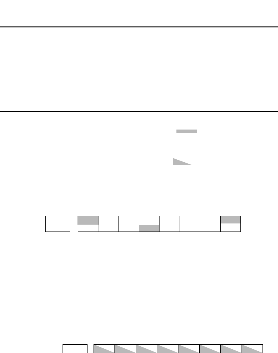
The half-tone dot meshing ( )has been described on the
non-effective signal in one side.
Please input the DI signal of the axis type based on the axis on the
turning mode.
The half-tone dot meshing ( )has been described on the
corresponding signal.
Example 1)
EXLM, *FLWU, RLSOT3, ST are common signals. STLK is the
signal of turning mode. RLSOT, RVS are the signals of milling mode.
Address 76543210
Turning
G007 RLSOT EXLM *FLWU RLSOT3 ST STLK RVS
Milling
Example 2)
The DI signal of the axis type is input based on the axis on the turning
mode.
When the same name as the motors in both modes was named as the
above-mentioned, 2
nd
axis (Z) in turning mode and 3
rd
axis (Z) in
milling mode are moved by turning +JV2 on in JOG mode.
Address #7 #6 #5 #4 #3 #2 #1 #0
G100 +JV8 +JV7 +JV6 +JV5 +JV4 +JV3 +JV2 +JV1
Turning : 1
s
t
axis X
2
nd
axis Z
3
rd
axis C
4
th
axis Y
Milling : 1
s
t
axis X
2
nd
axis Y
3
rd
axis Z
4
th
axis C
Contents Summary of FS 16i/18i-TB Compound Machining Function Additional Manual
- Page 1TECHNICAL REPORT (MANUAL) No.TMN 01/171E Date : Nov. 15, 2001 General Manager of Software Development Center FANUC Series 16i/18i-TB Compound Machining Function 1. Communicate this report to: Your information only ○ GE Fanuc-N, GE Fanuc-E FANUC Robotics MILACRON ○ Machine tool builder Sales agency E
- Page 2A-78656E/01 FANUC Series 16i/18i-TB Compound Machining Function FANUC Series 16i /18i -TB Compound Machining Function A-78656E/01 1/127 Nov.14.2001 Edition 1
- Page 3FANUC Series 16i/18i-TB Compound Machining Function A-78656E/01 Contents 1 General........................................................................................................................ 4 2 Specification ...............................................................................
- Page 4A-78656E/01 FANUC Series 16i/18i-TB Compound Machining Function 3.2.7 Signals............................................................................................................................ 65 3.3 Tool life management ......................................................................
- Page 5FANUC Series 16i/18i-TB Compound Machining Function A-78656E/01 1 General Compound machining function enables a single CNC to control turning and milling for a milling-turning compound machine. The function provides two modes, the turning and milling modes, and changes them by certain programming co
- Page 6A-78656E/01 FANUC Series 16i/18i-TB Compound Machining Function 2 Specification 5/127 Nov.14.2001 Edition 1
- Page 7FANUC Series 16i/18i-TB Compound Machining Function A-78656E/01 2.1 Command mode This function provides two modes, turning and milling modes. With changing modes, both programming command systems, T- system and M-system, are available. See the following references for the details of programming comm
- Page 8A-78656E/01 FANUC Series 16i/18i-TB Compound Machining Function In this function, it has the same restrictions as FS16i/18i -TB and FS16i /18i -MB have. Example) (1) In turning mode, X-axis and Z-axis should be assigned to the first and the 2nd axis, respectively in the following functions on 1 path
- Page 9FANUC Series 16i/18i-TB Compound Machining Function A-78656E/01 Example of CNC screen • Soft key 7 type Current mode Current displayed data T-MOD : Turning T-DSP : For Turning M-MOD : Milling M-DSP: For Milling • Soft key 12 type Nov.14.2001 Edition 1 8/127
- Page 10A-78656E/01 FANUC Series 16i/18i-TB Compound Machining Function Example of Programming Usually, two programs are required separately for turning and milling. This function enables you to include both turning and milling commands into a single program. Program for Milling Program for Turning O0001; O
- Page 11FANUC Series 16i/18i-TB Compound Machining Function A-78656E/01 2.2 On changing command modes On changing modes between turning and milling, the information for the modes is handled as follows. Data kind On changing modes G, F, S and D/H codes Data are independent for each mode. The data for the cur
- Page 12A-78656E/01 FANUC Series 16i/18i-TB Compound Machining Function 2.2.1 G code Modal G codes for both command modes are independent and never affect each other on changing them. For example, the modal G codes for turning mode are to be stored internally on changing to milling mode. They are to be rest
- Page 13FANUC Series 16i/18i-TB Compound Machining Function A-78656E/01 2.2.2 F code F codes for both command modes are also independent the same as G codes. They cannot be common especially because the values have different meanings depending on the current mode (feed/min. or feed/rev.), increment unit and
- Page 14A-78656E/01 FANUC Series 16i/18i-TB Compound Machining Function 2.2.4 T code Tool number specified by T code is common for both command modes. Though tool offset as well as tool number can be selected by T code in turning mode, that of milling mode is not affected from T code command in turning mode
- Page 15FANUC Series 16i/18i-TB Compound Machining Function A-78656E/01 2.2.6 Coordinate system Coordinate system for each command mode is independent, too. When axes are moved by motion commands, coordinate positions for both command modes are to be updated. With changing command modes, coordinate systems
- Page 16A-78656E/01 FANUC Series 16i/18i-TB Compound Machining Function 2.2.7 Reference point If a reference point of an axis is established in one command mode, that of the same axis in the other mode will be established automatically. The established reference points are physically the same on the machine
- Page 17FANUC Series 16i/18i-TB Compound Machining Function A-78656E/01 2.2.8 Diameter/Radius programming In turning mode, diameter/radius programming can be selected but not in milling mode. If a diameter-specified command for an axis is executed in turning mode, the coordinate position of the same axis fo
- Page 18A-78656E/01 FANUC Series 16i/18i-TB Compound Machining Function 2.2.10 Absolute/Incremental command Absolute/Incremental command is programmed differently between turning and milling modes. In milling mode, it is decided by modal G codes(G90/G91). In turning mode, it is decided by command addresses(
- Page 19FANUC Series 16i/18i-TB Compound Machining Function A-78656E/01 2.2.11 Tool offset It is impossible to change command modes with any tool offset effective. Tool offset for one mode is not applicable for the other because it has completely different meaning or effect for each mode. Example) O0008 ; N
- Page 20A-78656E/01 FANUC Series 16i/18i-TB Compound Machining Function 2.2.12 Spindle control On changing command modes, all spindles rotating by the current S code stops. S code must be newly commanded after changing them. Spindles may keep rotating by the setting of SAS(PRM No.13002#7) = 1 instead of sto
- Page 21FANUC Series 16i/18i-TB Compound Machining Function A-78656E/01 2.2.13 Axis control It is impossible to change modes while any axis is moving. At the block of the command mode selection M code, CNC confirms all axes stop and then executes the next block. Example) O0012 ; N1 M80 ; ← Turning mode star
- Page 22A-78656E/01 FANUC Series 16i/18i-TB Compound Machining Function 2.3 Switching CNC screens for turning and milling modes Some data such as parameters, offsets or so are independent for each command mode, turning and milling, because different values should be specified. 2.3.1 Display Switch Signal Th
- Page 23FANUC Series 16i/18i-TB Compound Machining Function A-78656E/01 2.4 Controlled axes 2.4.1 Axes configuration All controlled axes are commonly used for both command modes. Namely, all motors are used to control axes common for both modes. Therefore, there are some parameters setting required and rest
- Page 24A-78656E/01 FANUC Series 16i/18i-TB Compound Machining Function 2.4.3 Assigning servo axis number Correspondence between each axis number and servo axis number is not always the same for both command modes. Therefore, each axis-type parameter for milling mode must be specified based on the correspon
- Page 25FANUC Series 16i/18i-TB Compound Machining Function A-78656E/01 2.5 Spindle control 2.5.1 Connection Connection of spindle(serial) is available to use 4 spindles in FS16i, and 3 spindles in FS18. 2.5.2 Parameters It is common parameters in both command mode shown as following. ISI(No.3701#1) not use
- Page 26A-78656E/01 FANUC Series 16i/18i-TB Compound Machining Function 2.5.4 S command/rigid tap command With multi spindle function Select the commanded spindle by DI signal SWS1-SWS4(G0027#0- #3,G0026#3) with S command / rigid tap command. Specification is same as standard multi spindle function, and ref
- Page 27FANUC Series 16i/18i-TB Compound Machining Function A-78656E/01 2.5.5 Thread cutting / Feed per revolution With multi spindle function Which position coder of spindle will be selected by DI signal PC2SLC(G0028#8) in thread cutting / feed per revolution. Detail of specification is the same as standar
- Page 28A-78656E/01 FANUC Series 16i/18i-TB Compound Machining Function 2.5.6 Spindle speed at command mode changed Spindle rotation will stop automatically when the command mode is changed. It is available to do not stop spindle rotation with parameter SAS(No.13002#7)=1. #7 #6 #5 #4 #3 #2 #1 #0 13002 SAS S
- Page 29FANUC Series 16i/18i-TB Compound Machining Function A-78656E/01 2.6 Alarms All alarms will be displayed on the same alarm screen regardless of command modes. Alarms for turning mode and for milling are displayed on separated display. Nov.14.2001 Edition 1 28/127
- Page 30A-78656E/01 FANUC Series 16i/18i-TB Compound Machining Function 2.7 Manual operation In a manual operation, Axis number is used in turning mode. Example) Axis structure in turning mode 1st - X, 2nd - Z, 3rd - C In case motors is had in common with the same name in turning mode and milling mode, C ax
- Page 31FANUC Series 16i/18i-TB Compound Machining Function A-78656E/01 2.8 DI/DO signals Signals ranged G000 – G255 and F000 – F255 are are used normally for both modes. G1000 – G1255 and F1000 – F1255 may be used specially for some part of milling. See the following references for the details of DI/DO sig
- Page 32A-78656E/01 FANUC Series 16i/18i-TB Compound Machining Function Address table (Input signals) Address #7 #6 #5 #4 #3 #2 #1 #0 ESKIP ZAEt XAEt X004 SKIPt SKIP6t SKIP5t SKIP4t SKIP3t SKIP2t SKIP8t SKIP7t X008 *ESP X009 *DEC7 *DEC6 *DEC5 *DEC4 *DEC3 *DEC2 *DEC1 *DEC0 ZAEm YAEm XAEm X013 SKIPm SKIP6m SK
- Page 33FANUC Series 16i/18i-TB Compound Machining Function A-78656E/01 Address #7 #6 #5 #4 #3 #2 #1 #0 G031 PKESS2 PKESS1 G032 R08I R07I R06I R05I R04I R03I R02I R01I G033 SIND SSIN SGN R12I R11I R10I R09I G034 R08I2 R07I2 R06I2 R05I2 R04I2 R03I2 R02I2 R01I2 G035 SIND2 SSIN2 SGN2 R12I2 R11I2 R10I2 R09I2 G0
- Page 34A-78656E/01 FANUC Series 16i/18i-TB Compound Machining Function Address #7 #6 #5 #4 #3 #2 #1 #0 G071 RCHA RSLA INTGA SOCNA MCFNA SPSLA *ESPA ARSTA G072 RCHHGAMFNHGA INCMDA OVRIDA DEFMDA NRROA ROTAA INDXA G073 MPOFA SLVA MORCMA G074 MRDYB ORCMB SFRB SRVB CTH1B CTH2B TLMHB TLMLB G075 RCHB RSLB INTGB S
- Page 35FANUC Series 16i/18i-TB Compound Machining Function A-78656E/01 Address #7 #6 #5 #4 #3 #2 #1 #0 G111 G112 -LM8 -LM7 -LM6 -LM5 -LM4 -LM3 -LM2 -LM1 G113 G114 *+L8 *+L7 *+L6 *+L5 *+L4 *+L3 *+L2 *+L1 G115 G116 *-L8 *-L7 *-L6 *-L5 *-L4 *-L3 *-L2 *-L1 G117 G118 *+ED8 *+ED7 *+ED6 *+ED5 *+ED4 *+ED3 *+ED2 *+
- Page 36A-78656E/01 FANUC Series 16i/18i-TB Compound Machining Function Address #7 #6 #5 #4 #3 #2 #1 #0 G151 *FV7E *FV6E *FV5E *FV4E *FV3E *FV2E *FV1E G152 G153 G154 EBUFB ECLRB ESTPB ESOFB ESBKB EMBUFB EFINB G155 EMSBKB EC6B EC5B EC4B EC3B EC2B EC1B EC0B G156 EIF7B EIF6B EIF5B EIF4B EIF3B EIF2B EIF1B EIF0B
- Page 37FANUC Series 16i/18i-TB Compound Machining Function A-78656E/01 Address #7 #6 #5 #4 #3 #2 #1 #0 G191 G192 IGVRY8 IGVRY7 IGVRY6 IGVRY5 IGVRY4 IGVRY3 IGVRY2 IGVRY1 G193 PTM DTM G194 G195 G196 G197 G198 NPOS8 NPOS7 NPOS6 NPOS5 NPOS4 NPOS3 NPOS2 NPOS1 G199 G200 G201 G202 G203 G204 MRDYCA ORCMC SFRC SRVC
- Page 38A-78656E/01 FANUC Series 16i/18i-TB Compound Machining Function Address #7 #6 #5 #4 #3 #2 #1 #0 G231 G232 G233 G234 G235 G236 G237 G238 G239 G240 G241 G242 G243 G244 G245 G246 G247 G248 G249 G250 G251 G252 G253 G254 G255 Address #7 #6 #5 #4 #3 #2 #1 #0 G1000 ED7 ED6 ED5 ED4 ED3 ED2 ED1 ED0 G1001 ED1
- Page 39FANUC Series 16i/18i-TB Compound Machining Function A-78656E/01 2.8.2 DO signals DO signals of Compound Machining Function are had in common in turning mode and milling mode. DO signals for milling mode is output to F000 and after only in milling mode. The half-tone dot meshing ( )has been described
- Page 40A-78656E/01 FANUC Series 16i/18i-TB Compound Machining Function Address table (Output signals) Address #7 #6 #5 #4 #3 #2 #1 #0 F000 OP SA STL SPL RWD F001 MA TAP ENB DEN BAL RST AL F002 MDRN CUT SRNMV THRD CSS RPDO INCH F003 MTCHIN MEDT MMEM MRMT MMDI MJ MH MINC F004 MREF MAFL MSBK MABSM MMLK MBDT F
- Page 41FANUC Series 16i/18i-TB Compound Machining Function A-78656E/01 Address #7 #6 #5 #4 #3 #2 #1 #0 F041 AR15 AR14 AR13 AR12 AR11 AR10 AR09 AR08 F042 F043 F044 SYCAL FSPPH FSPSY FSCSL F045 ORARA TLMA LDT2A LDT1A SARA SDTA SSTA ALMA F046 MORA2A MORA1A PORA2A SLVSA RCFNA RCHPA CFINA CHPA F047 INCSTA PC1DE
- Page 42A-78656E/01 FANUC Series 16i/18i-TB Compound Machining Function Address #7 #6 #5 #4 #3 #2 #1 #0 F081 -J4O +J4O -J3O +J3O -J2O +J2O -J1O +J1O F082 RVSL F083 F084 F085 F086 F087 F088 F089 F090 ABTSP2 ABTSP1 ABTQSV F091 F092 TRSPS TRACT F093 F094 ZP8 ZP7 ZP6 ZP5 ZP4 ZP3 ZP2 ZP1 F095 F096 ZP28 ZP27 ZP26
- Page 43FANUC Series 16i/18i-TB Compound Machining Function A-78656E/01 Address #7 #6 #5 #4 #3 #2 #1 #0 F121 F122 HDO7 HDO6 HDO5 HDO4 HDO3 HDO2 HDO1 HDO0 F123 F124 F125 F126 F127 F128 F129 *EAXSL EOV0 F130 EBSYA EOTNA EOTPA EGENA EDENA EIALA ECKZA EINPA F131 EABUFA EMFA F132 EM28A EM24A EM22A EM21A EM18A EM
- Page 44A-78656E/01 FANUC Series 16i/18i-TB Compound Machining Function Address #7 #6 #5 #4 #3 #2 #1 #0 F161 F162 F163 F164 F165 F166 F167 F168 F169 F170 F171 F172 F173 F174 F175 F176 F177 F178 F179 F180 F181 F182 F183 F184 F185 F186 F187 F188 F189 F190 F191 F192 F193 PRS F194 F195 F196 F197 F198 F199 F200
- Page 45FANUC Series 16i/18i-TB Compound Machining Function A-78656E/01 Address #7 #6 #5 #4 #3 #2 #1 #0 F201 F202 F203 F204 F205 F206 F207 F208 F209 F210 F211 F212 F213 F214 F215 F216 F217 F218 F219 F220 F221 F222 F223 F224 F225 F226 F227 F228 F229 F230 F231 F232 F233 F234 F235 F236 F237 F238 F239 F240 Nov.
- Page 46A-78656E/01 FANUC Series 16i/18i-TB Compound Machining Function Address #7 #6 #5 #4 #3 #2 #1 #0 F241 F242 F243 F244 F245 F246 F247 F248 F249 F250 F251 F252 F253 F254 F255 Address #7 #6 #5 #4 #3 #2 #1 #0 F1060 ESEND EREND F1072 OUT7 OUT6 OUT5 OUT4 OUT3 OUT2 OUT1 OUT0 F1073 ZRNO MD4O MD2O MD1O F1074 F
- Page 47FANUC Series 16i/18i-TB Compound Machining Function A-78656E/01 2.9 Parameters Basically, the parameters are set in turning mode and in milling mode each. However, there are common parameters in both modes such as servo parameters. The common parameters are displayed only on turning display screen.
- Page 48A-78656E/01 FANUC Series 16i/18i-TB Compound Machining Function 2.10 Custom macro variable Custom macro variable is separate in turning mode and milling mode. As for common variables for custom macro # 100-#149 and # 500- #531, the use can be done together between modes according to the parameter (N
- Page 49FANUC Series 16i/18i-TB Compound Machining Function A-78656E/01 3 Differences from standard T/M-system controls Some turning and milling features of this function are different from the standard T/M-system controls’. This chapter explains the details. Nov.14.2001 Edition 1 48/127
- Page 50A-78656E/01 FANUC Series 16i/18i-TB Compound Machining Function 3.1 Tool selection, tool offset When T code is commanded, the code signals and strobe signal are to be output for a machine to select a tool. T code command for standard T-system control specifies a tool offset and validates it at the s
- Page 51FANUC Series 16i/18i-TB Compound Machining Function A-78656E/01 3.1.2 Tool offset The parameter setting of TO2(No.13001#1) = 1 allows you to activate/deactivate tool offset not by T code only but G code. The following format combined with T code and G code is used to start tool offset. Tool offset O
- Page 52A-78656E/01 FANUC Series 16i/18i-TB Compound Machining Function Tool offset number command by D code In standard T system, both tool number and tool offset number are specified by T code. In compound machining function, tool offset number is specified by D code in case of parameter 13001#2(DOF)=1. I
- Page 53FANUC Series 16i/18i-TB Compound Machining Function A-78656E/01 3.2 The compensation according to the angle of B-axis If B axis is rotated when the measurement reference position of the offset is different from B axis rotation center position, the measurement reference position slides according to t
- Page 54A-78656E/01 FANUC Series 16i/18i-TB Compound Machining Function 3.2.2 Tool Offset Value Conversion according to the Angle of B- axis (T mode) Features and outlines The offset values are never to memorize the one at the position of B=0°. The ones of the current angle is memorized. That is, if the amo
- Page 55FANUC Series 16i/18i-TB Compound Machining Function A-78656E/01 Offset value at B=-90° when based on B=0° OFSx + Px - Pz (-OFSz) + (-Pz) + (-Px) Offset value at B=90° (-OFSx) + (-Px) – Pz when based on B=0° OFSz + Pz - Px Nov.14.2001 Edition 1 54/127
- Page 56A-78656E/01 FANUC Series 16i/18i-TB Compound Machining Function The angle (-90°/0°/90°) of B axis is notified to CNC by not the coordinates value but R signal. And, the address of the R signal is specified by the parameter. Please do not input the signal, except for the above-mentioned angle. For th
- Page 57FANUC Series 16i/18i-TB Compound Machining Function A-78656E/01 3.2.3 Example of Tool Geometry Offset Measurement Parameter Setting As for parameter No.5015∼5018 for the direct input of offset value measured B, the distance between the touch sensor and the base of the tool when the tool turns downwa
- Page 58A-78656E/01 FANUC Series 16i/18i-TB Compound Machining Function Example Rotation center shift amount Z Prm. 13042 = 10 (0.020 : diameter setting) Rotation center (0.010 : radius setting) shift amount X Prm. 13041 = 500000 (500.000 : diameter setting) (250.000 : radius setting) -190.000 -626.000 Exte
- Page 59FANUC Series 16i/18i-TB Compound Machining Function A-78656E/01 Measurement CNC recognizes the angle (-90°/0°/90°) of B-axis according to not the coordinates value but R signal. And, the address of the R signal is specified by the parameter. The signal must not be input, except for the above-mention
- Page 60A-78656E/01 FANUC Series 16i/18i-TB Compound Machining Function The distance between the B-axis rotation center point and the base of the tool is set in the tool geometry offset value as follows. OFSx = -580.020 = -500.000 - 0.020 - 80.000 OFSz = 379.990 = -0.010 + 250.000 + 130.000 130.000 80.000 (
- Page 61FANUC Series 16i/18i-TB Compound Machining Function A-78656E/01 The direction of the 2 3 4 imaginary tool nose Inside or outside inside inside inside of the tool The direction of the 3 4 1 imaginary tool nose Inside or outside outside outside outside of the tool Conversion into downward (B0°) 1. B a
- Page 62A-78656E/01 FANUC Series 16i/18i-TB Compound Machining Function Conversion into rightward (B90°) 1. B axis is rotated to 90 degrees. 2. The bit 2 of R address of this signal specified with the parameter 13040 is set to “1”. The bit 0 and 1 of it is set to “0”. 3. T-code is commanded in MDI or MEM mo
- Page 63FANUC Series 16i/18i-TB Compound Machining Function A-78656E/01 3.2.4 Coordinate Value Compensation in 3-D Coordinate conversion according to the Angle of B-axis (M mode) Example of machining Pz the end face of The direction of spindle in doing (B0°) workpiece as B=-90° three-dimensional coordinates
- Page 64A-78656E/01 FANUC Series 16i/18i-TB Compound Machining Function Example of machining The direction of spindle in the the side face of workpiece Pz actual machining and the as B=0°° direction of spindle when the (B0°) former three dimensional Px coordinate conversion is only executed (B=0) +Z’ B axis
- Page 65FANUC Series 16i/18i-TB Compound Machining Function A-78656E/01 3.2.5 Parameters #7 #6 #5 #4 #3 #2 #1 #0 13000 BA3D BGWO BGWO Tool Offset Value Conversion according to the Angle of B-axis (T mode) is : 0: Not available. 1: available. BA3D Coordinate Value Compensation in 3-D Coordinate conversion ac
- Page 66A-78656E/01 FANUC Series 16i/18i-TB Compound Machining Function 3.2.6 Alarm 5309 IMPROPER B-AXIS ANGLE In Turning mode, the command which make the offset value effective is specified when the angle of B-axis is –90 degrees, 0 degrees, or 90 degrees. 3.2.7 Signals Address #7 #6 #5 #4 #3 #2 #1 #0 R***
- Page 67FANUC Series 16i/18i-TB Compound Machining Function A-78656E/01 3.3 Tool life management The compound machining function has two command modes which are a turning mode and a milling mode. Tools for turning and milling are housed in a common magazine. Therefore, both kinds of tools have to be managed
- Page 68A-78656E/01 FANUC Series 16i/18i-TB Compound Machining Function Tool life management Machining Machine and data program CNC operations Tool Machine CNC group number 1 . . Places a Automatically . . selected tool selects, from Tool Tool Command in the wait tool group m, group selection for state a to
- Page 69FANUC Series 16i/18i-TB Compound Machining Function A-78656E/01 Tool number Turning mode: In case of parameter 13001#2(DOF)=0, specify a upper two- digit number in T code In case of parameter 13001#2(DOF)=1, the entire T code indicates tool number. Milling mode: The entire T code indicates tool numb
- Page 70A-78656E/01 FANUC Series 16i/18i-TB Compound Machining Function 3.3.3 Register, Change and Delete of Tool Life Management Data In program, tool life management data can be registered in the CNC unit, and registered tool life management data can be changed or deleted. Register with deleting all group
- Page 71FANUC Series 16i/18i-TB Compound Machining Function A-78656E/01 Deletion of tool life management data Programmed tool life management data for a group can be deleted. Format Meaning of common G10L3 P2 ; G10L3 P2 :deletion of group P__ ; P__ :Group number P__ ; G11 :End of deletion of group P__ ; G11
- Page 72A-78656E/01 FANUC Series 16i/18i-TB Compound Machining Function 3.3.4 Tool life management command in a machining program Tool group is specified by T code in a machining program. The way specifying the tool group and the tool offset number are deference between in turning mode and in milling mode.
- Page 73FANUC Series 16i/18i-TB Compound Machining Function A-78656E/01 Example) Parameter No. 6810 = 100 (Tool life management cancel number) Oxxxx; T010199; A tool whose life has not expired is selected from group 1. M06; The selected tool (in group1) is used for machining. G43; The tool offset of the cur
- Page 74A-78656E/01 FANUC Series 16i/18i-TB Compound Machining Function H99; Selects the H code of tool life management data for the tool currently being used. H00; Cancels tool length offset. D99; Selects the D code of tool life management data for the tool currently being used. D00; Cancels cutter compens
- Page 75FANUC Series 16i/18i-TB Compound Machining Function A-78656E/01 3.3.5 Tool life The life of tool is specified by a usage frequency (count) or usage time (in minutes.) Usage count The usage count is incremented by 1 for each tool used in a program. In other words, the usage count is incremented by 1
- Page 76A-78656E/01 FANUC Series 16i/18i-TB Compound Machining Function NOTE 1. When a tool is selected from available tools, tools are searched starting from the current tool towards the last tool to find a tool whose life has not expired. When the last tool is searched during this search, the search resta
- Page 77FANUC Series 16i/18i-TB Compound Machining Function A-78656E/01 1. Press function key [OFFSET] 2. Press the continuous menu key [+] to display chapter selection soft key [TOOLLF]. 3. Press soft key [TOOLLF]. 4. One page displays data on two groups. Pressing page key “↑” or “↓” successively displays
- Page 78A-78656E/01 FANUC Series 16i/18i-TB Compound Machining Function • The first line is the title line. • In the second line, the group number of the current command is displayed. When there is no group number of the current command, 0 is displayed. • In lines 3 to 7, the tool life data of the group is
- Page 79FANUC Series 16i/18i-TB Compound Machining Function A-78656E/01 3.4 DNC Operation In the compound machining function, it is possible to perform DNC Operation as follows. 3.4.1 I/O Channel This function can be used under the following channels. 0∼2 : RS232-C 3 : Remote Buffer 5 : Data Server 3.4.2 No
- Page 80A-78656E/01 FANUC Series 16i/18i-TB Compound Machining Function 3.5 Restrictions In compound machining function, some functions have restrictions even if they are available in the standard T/M system. Their contents are described. 3.5.1 Restrictions of Compound Machining Function Polar Interpolation
- Page 81FANUC Series 16i/18i-TB Compound Machining Function A-78656E/01 4 Additional parameters The following parameters have been added for the function. Nov.14.2001 Edition 1 80/127
- Page 82A-78656E/01 FANUC Series 16i/18i-TB Compound Machining Function 4.1 Bit type parameters #7 #6 #5 #4 #3 #2 #1 #0 13000 BA3D BGWO TMD0 TMD0 When M code for changing turning/milling modes is commanded from CNC program, code signals and strobe signal are: 0: To be output. 1: Not to be output. BGWO Tool
- Page 83FANUC Series 16i/18i-TB Compound Machining Function A-78656E/01 #7 #6 #5 #4 #3 #2 #1 #0 13002 SAS MDD GW2 EPM TMD TMD Turning/milling data confirmation display is: 0: Unavailable. 1: Available. EPM Change between turning mode and milling mode is performed by 0: Only mode selection M code. 1: Mode se
- Page 84A-78656E/01 FANUC Series 16i/18i-TB Compound Machining Function NOTE 1. In condition of parameter SAS=1, the rotation speed of spindle that is selected by DI signal SWS1- SWS4(G027#0-#2, G026#3) =1 with multi spindle function will be used last commanded S code. Please be careful to make PMC ladder p
- Page 85FANUC Series 16i/18i-TB Compound Machining Function A-78656E/01 4.2 Byte type parameters 13010 Spindle number to be commanded by S command / rigid tap command [Data type] Byte [Data range] 0 to 4 Set the spindle number will be controlled by S command / rigid tap command without multi spindle functio
- Page 86A-78656E/01 FANUC Series 16i/18i-TB Compound Machining Function 13030 Axis number in turning mode corresponding to each axis in milling mode [Data type] Byte axis [Data range] 1 to Controlled axes number for turning mode Each axis-type parameter for milling mode must be specified based on the corres
- Page 87FANUC Series 16i/18i-TB Compound Machining Function A-78656E/01 4.3 Word type parameters The address of R signal for the tool offset value conversion according to the 13040 angle of B-axis [Data type] Word [Data range] 0 to 65536 As for Tool Offset Value Conversion according to the Angle of B- axis
- Page 88A-78656E/01 FANUC Series 16i/18i-TB Compound Machining Function 4.4 Double word type parameters 13020 M code to switch the modes from milling to turning 13021 M code to switch the modes from turning to milling [Data type] Double word [Data range] 3 to 99999999 M code by which the turning mode and th
- Page 89FANUC Series 16i/18i-TB Compound Machining Function A-78656E/01 5 Additional signals The following signals have been added for the function. Nov.14.2001 Edition 1 88/127
- Page 90A-78656E/01 FANUC Series 16i/18i-TB Compound Machining Function 5.1 DI signal Address #7 #6 #5 #4 #3 #2 #1 #0 G193 PTM DTM DTM The following screen is displayed by this signal. 0: The screen showing turning data is displayed. 1: The screen showing milling data is displayed. PTM The change between tu
- Page 91FANUC Series 16i/18i-TB Compound Machining Function A-78656E/01 5.2 DO signal Address #7 #6 #5 #4 #3 #2 #1 #0 F193 PRS PRS Current mode is: 0: Milling one. 1: Turning one. Nov.14.2001 Edition 1 90/127
- Page 92A-78656E/01 FANUC Series 16i/18i-TB Compound Machining Function 5.3 R area Address #7 #6 #5 #4 #3 #2 #1 #0 R??? TRV B90 B00 B-90 B90,B00,B-90 The angle of B-axis inputted from PMC * There is no need to set this signal except the case that the angle of B-axis is –90, 0 or 90. TRV The direction of the
- Page 93FANUC Series 16i/18i-TB Compound Machining Function A-78656E/01 6 Additional alarms The following signals have been added for the function. 5253 T/M MODE CAN NOT BE SWITCHED Turning/milling modes cannot be changed in spite of commanding M code for it. The followings are possible causes. - The M code
- Page 94A-78656E/01 FANUC Series 16i/18i-TB Compound Machining Function 213 ILLEGAL COMMAND IN SYNCHRO-MODE The relation of coordinate systems between turning and milling modes are no longer correct. 5309 IMPROPER B-AXIS ANGLE In turning mode, the offset can be specified only with B-90, B00, and B90 93/127
- Page 95FANUC Series 16i/18i-TB Compound Machining Function A-78656E/01 7 Specifications Ο : Standard ● : Standard option ✩ : Option ✳ : Function include in another option Note) Some combinations of these options are restricted. Some functions have restrictions even if they are available in the standard T/M
- Page 96A-78656E/01 FANUC Series 16i/18i-TB Compound Machining Function Turning Milling Item Specifications mode mode Axis recomposition - Simple synchronous control - Twin table control - Angular axis control - Arbitrary angular axis control ✩ B-axis control - Tandem control - Torque control PMC axis contr
- Page 97FANUC Series 16i/18i-TB Compound Machining Function A-78656E/01 Turning Milling Item Specifications mode mode Mirror image each axis Ο Follow-up Ο Servo off / mechanical Ο handle feed Chamfering on/off Ο - Backlash compensation Ο Backlash compensation for each Ο rapid traverse and cutting feed Store
- Page 98A-78656E/01 FANUC Series 16i/18i-TB Compound Machining Function Operation Turning Milling Item Specifications mode mode Automatic operation Ο (memory) DNC operation Reader / puncher interface ✩ is required. MDI operation Ο Schedule function Ο Program number search Ο Sequence number search Ο Sequence
- Page 99FANUC Series 16i/18i-TB Compound Machining Function A-78656E/01 Interpolation functions Turning Milling Item Specifications mode mode Positioning Linear interpolation type Ο positioning is possible. Single direction positioning - ✩ Exact stop mode - Ο Exact stop - Ο Linear interpolation Ο Circular i
- Page 100A-78656E/01 FANUC Series 16i/18i-TB Compound Machining Function Turning Milling Item Specifications mode mode Reference position return Ο Reference position return Ο check 2nd reference position return Ο 3rd/4th reference position ✩ return Floating reference position ✩ return Normal direction contro
- Page 101FANUC Series 16i/18i-TB Compound Machining Function A-78656E/01 Feed functions Turning Milling Item Specifications mode mode Rapid traverse rate Max. 240m/min (1µm) Ο Max. 100m/min (0.1µm) ✳ Rapid traverse override F0, 25, 50, 100% Ο Feed per minute Ο Feed per revolution Ο Feed per revolution Ο - wi
- Page 102A-78656E/01 FANUC Series 16i/18i-TB Compound Machining Function Program input Turning Milling Item Specifications mode mode Tape code EIA RS244/ISO840 Ο automatic recognition Label skip Ο Parity check Horizontal and vertical parity Ο Control in/out Ο Optional block skip 1 Ο 9 ✩ Max. programmable ±8-
- Page 103FANUC Series 16i/18i-TB Compound Machining Function A-78656E/01 Turning Milling Item Specifications mode mode Manual absolute on and off Ο Direct drawing dimension ✩ - programming G code system A Ο - B/C ✩ - Chamfering/corner R ✩ - Optional chamfering/corner - ✩ R Programmable data input ✩ Sub progr
- Page 104A-78656E/01 FANUC Series 16i/18i-TB Compound Machining Function Conversational programming function for machining center Turning Milling Item Specifications mode mode Super CAP II M - Super CAP M - NC format output - Conversational C language - programming Contour figure repetition - Background grap
- Page 105FANUC Series 16i/18i-TB Compound Machining Function A-78656E/01 Conversational programming function for lathe Turning Milling Item Specifications mode mode Super CAP II T - Super CAP T - NC format output - C-axis conversational - programming Y-axis conversational - programming P code macro variable
- Page 106A-78656E/01 FANUC Series 16i/18i-TB Compound Machining Function Auxiliary/spindle speed function Turning Milling Item Specifications mode mode Auxiliary function M8-digit Ο 2nd auxiliary function B8-digit ✩ Auxiliary function lock Ο High-speed M/S/T/B Ο interface Waiting function - Multiple command
- Page 107FANUC Series 16i/18i-TB Compound Machining Function A-78656E/01 Tool function/tool compensation Turning Milling Item Specifications mode mode Tool function T6+2 digit Ο - T8 digit - Ο Tool offset pairs ±6-digit 32 turning mode Ο 64 milling mode ±6-digit 64 turning mode ✩ 99 milling mode ±6-digit 99
- Page 108A-78656E/01 FANUC Series 16i/18i-TB Compound Machining Function Turning Milling Item Specifications mode mode Tool offset value Ο - counter input Tool length measurement - ✩ Automatic tool length - ✩ Measurement Tool length/work zero point - - Measurement B Automatic tool offset ✩ - Direct input of
- Page 109FANUC Series 16i/18i-TB Compound Machining Function A-78656E/01 Editing operation Turning Milling Item Specifications mode mode Part program storage length 40m Ο 80m ✩ 160m ✩ 320m ✩ 640m ✩ 1280m ✩ 2560m - 5120m - Number of registrable 63 Ο programs 125 ✩ 200 ✩ 400 ✩ 1000 ✩ Part program editing Ο Pro
- Page 110A-78656E/01 FANUC Series 16i/18i-TB Compound Machining Function Setting and display Turning Milling Item Specifications mode mode Status display Ο Clock function Ο Current position display Ο Program display Program name 31 characters Ο Parameter setting and Ο display Self-diagnosis function Ο Alarm
- Page 111FANUC Series 16i/18i-TB Compound Machining Function A-78656E/01 Turning Milling Item Specifications mode mode Display of hardware and software Ο configuration Periodic maintenance screen Ο Maintenance information Ο screen Software operator’s panel ✩ Software operator’s panel general ✩ purpose switch
- Page 112A-78656E/01 FANUC Series 16i/18i-TB Compound Machining Function Data input/output Turning Milling Item Specifications mode mode Reader/puncher interface Reader/puncher (Ch.1) ✩ interface Reader/puncher (Ch.2) ✩ interface Input/output simultaneous - operation Remote buffer ✩ High-speed remote buffer
- Page 113FANUC Series 16i/18i-TB Compound Machining Function A-78656E/01 Others Turning Milling Item Specifications mode mode Status output signal NC ready, servo ready, Automatic operation, automatic operation start lamp, feed hold, reset, NC alarm, distribution end, Ο rewinding, inch input, cutting, inposi
- Page 114A-78656E/01 FANUC Series 16i/18i-TB Compound Machining Function Turning Milling Item Specifications mode mode PMC-SB5 Basic instruction: 0.085 µsec/step - Max. step number ladder: 24,000 PMC-SB6 Basic instruction: 0.085 µsec/step PMC Max. step number ladder: ● system 32,000 Step sequence function PM
- Page 115FANUC Series 16i/18i-TB Compound Machining Function A-78656E/01 8 Starting Compound Machining Function Procedure of Nov.14.2001 Edition 1 114/127
- Page 116A-78656E/01 FANUC Series 16i/18i-TB Compound Machining Function 8.1 Outline The compound machining function is realized with the system software only for the compound machining function. Therefore, the loading to F-ROM, the parameter setting procedure, and so on are different from the standard syste
- Page 117FANUC Series 16i/18i-TB Compound Machining Function A-78656E/01 8.1.3 Loading to F-ROM The system software of the compound machining function consists of the following software. It is necessary to install those all in F-ROM. File Name on F-ROM System software for turning Basic NC BASIC System softwa
- Page 118A-78656E/01 FANUC Series 16i/18i-TB Compound Machining Function 8.2 Manual Parameter Setting The parameter for turning mode(T-MOD) is set on the screen of turning mode(T-DSP), and the same for milling mode(M-MOD,M- DSP). The common parameter of both mode can be set on the screen of both mode(T-DSP,M
- Page 119FANUC Series 16i/18i-TB Compound Machining Function A-78656E/01 8.2.2 Parameter to relate axes of the turning side to ones of the milling side (No.13030) You set the parameter No. 13030 to relate axes of the turning side to ones of the milling side. The axis number which is controlled in the turning
- Page 120A-78656E/01 FANUC Series 16i/18i-TB Compound Machining Function 8.2.3 Parameter of the Number of The Servo Axis for Each Axis (No.1023) You set the parameter no. 1023 to the servo axis number for each control axis in the turning side(T-DSP). Procedure 1. You set DI signal G193#0(DTM) to “0” in order
- Page 121FANUC Series 16i/18i-TB Compound Machining Function A-78656E/01 8.2.5 Servo Parameter (No.2000∼ ∼2413, No.1820 etc.) You set the servo parameter automatically. Procedure 1. You set DI signal G193#0(DTM) to “0” in order to display the screen of the turning side (T-DSP) display. 2. You change the oper
- Page 122A-78656E/01 FANUC Series 16i/18i-TB Compound Machining Function 8.2.6 Spindle Parameter(No.4000∼ ∼4799, No.3701etc.) You set the spindle parameter automatically. Procedure 1. You set DI signal G193#0(DTM) to “0” in order to display the screen of the turning side (T-DSP) display. 2. You set the spind
- Page 123FANUC Series 16i/18i-TB Compound Machining Function A-78656E/01 8.3 Parameter Input from I/O Device The method of starting up CNC by using the parameter file backed up is explained 8.3.1 Input of Parameter for Turning Mode (The First Time) The parameter for the turning mode is input in order to set
- Page 124A-78656E/01 FANUC Series 16i/18i-TB Compound Machining Function 8.3.3 Input of Parameter for Turning Mode (The Second Time) The parameter for the turning mode (T-MOD) is input again in order to set the parameter for the optional function such as the parameter no. 9000 for the macro executor. Procedu
- Page 125FANUC Series 16i/18i-TB Compound Machining Function A-78656E/01 8.4 Axis Type of Common Parameter In the compound machining function, notes in case of setting the axis type of the common parameter for both the turning mode (T-MOD) and the milling mode (M-MOD) are described. The axis type of common p
- Page 126A-78656E/01 FANUC Series 16i/18i-TB Compound Machining Function When the 2nd axis of the parameter no. 1420 for the milling mode (M- MOD) is set to “24000”, the 4th axis of the parameter no. 1420 for the turning mode (T-MOD) is also automatically set to “24000”. T-MOD Value of the M-MOD Value of the
- Page 127FANUC Series 16i/18i-TB Compound Machining Function A-78656E/01 Axis Type of Common Parameter List No. 1005 No. 1007 No. 1008 No. 1012 No. 1022 No. 1420 No. 1421 No. 1423 No. 1424 No. 1425 No. 1427 No. 1815 No. 1816 No. 1817 No. 1818 No. 1819 No. 1820 No. 1821 No. 1825 No. 1826 No. 1827 No. 1828 No.
- Page 128A-78656E/01 FANUC Series 16i/18i-TB Compound Machining Function No. 2180 No. 2181 No. 2182 No. 2183 No. 2184 No. 2185 No. 2186 No. 2187 No. 2188 No. 2189 No. 2190 No. 2191 No. 2192 No. 2193 No. 2194 No. 2195 No. 2196 No. 2197 No. 2198 No. 2199 No. 2200 No. 2201 No. 2202 No. 2203 No. 2204 No. 2205 No