Profibus DP-Board for Operators manual Page 101
Operators manual
B-63994EN/02 SUPPLEMENT B.EXAMPLE OF SETTING
- 93 -
B.1 EXAMPLE OF CONNECTION
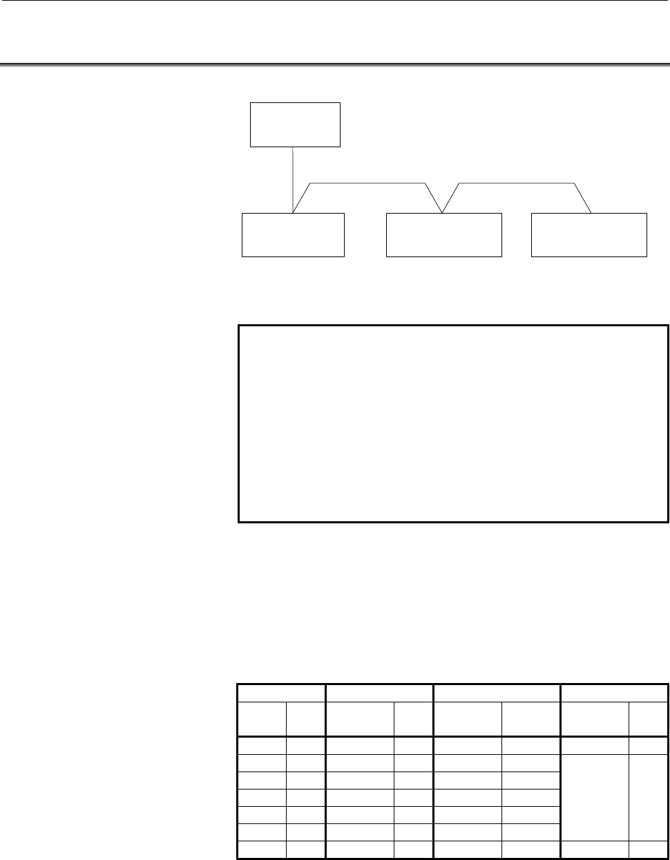
The example of setting explains according to the following system.
Remote I/O device
DP-Slave#4
Series 30
i
-A
(DP-Master#1)
Power Mate
i
-D
DP-Slave#3
DI: 64 signals
DO: 64 signals
DI: 8 signals
DO: 8 signals
DI:
8 signals
DO:
8 signals
PROFIBUS
Remote I/O device
DP-Slave#5
Example of connection
Remark
In this example, the following WAGO’s I/O system is used as
the instance of a remote I/O device.
750-333 (Communication module)
750-402 (4 channel DI module)
750-402 (4 channel DI module)
750-504 (4 channel DO module)
750-504 (4 channel DO module)
750-600 (Terminal module)
As for the settings of your system, please set-up according to
your slaves, referring to this example
.
Series 30i-A acts as Master, and it connects with Power Mate i-D
(Slave #3) and Remote I/O devices (Slave #4 and #5).
As for Slave #4 which consists of four I/O modules, each I/O module
is assigned to PMC address of 30i-A separately. Meanwhile, I/Os of
Slave #5 is assigned to PMC address lumped together.
DI/DO signals are assigned to PMC addresses as follows.
Slave DI DO Diagnostic data
Slave
No.
Slot
No.
Address Size Address Size Address Size
#3 0 R0100 8 R0200 8 R0300 6
#4 0 0 0
1 R0110 1 0
2 R0120 1 0
3 0 R0210 1
4 0 R0220 1
R0310 6
#5 0 R0130 2 R0230 2 R0320 6
Contents Summary of Profibus DP-Board for Operators manual
- Page 1FANUC PROF IBUS-DP Board For FANUC Series 30*/300*, 31*/310*, 32*/320*-MODEL A OPERATOR’S MANUAL B-63994EN/02
- Page 2• No part of this manual may be reproduced in any form. • All specifications and designs are subject to change without notice. The export of this product is subject to the authorization of the government of the country from where the product is exported. In this manual we have tried as much as possi
- Page 3B-63994EN/02 SAFETY PRECAUTIONS SAFETY PRECAUTIONS This section describes the safety precautions related to the use of CNC units, to ensure safe operation of machines fitted with FANUC CNC units. Read this section carefully before attempting to use any function described in this manual. Users should
- Page 4SAFETY PRECAUTIONS B-63994EN/02 1.1 DEFINITION OF WARNING, CAUTION, AND NOTE This manual includes safety precautions for protecting the user and preventing damage to the machine. Precautions are classified into Warning and Caution according to their bearing on safety. Also, supplementary information
- Page 5B-63994EN/02 SAFETY PRECAUTIONS 1.2 GENERAL WARNINGS AND NOTES WARNING 1 Before operating the machine, thoroughly check the entered data. Operating the machine with incorrect data may result in the machine behaving unexpectedly, possibly causing damage to the workpiece and/or machine itself, or inju
- Page 6SAFETY PRECAUTIONS B-63994EN/02 CAUTION 1 Immediately after switching on the power, do not touch any of the keys on the MDI panel until the position display or alarm screen appears on the CNC unit. Some of the keys on the MDI panel are dedicated to maintenance or other special operations. Pressing a
- Page 7B-63994EN/02 TABLE OF CONTENTS TABLE OF CONTENTS SAFETY PRECAUTIONS............................................................................s-1 I. GENERAL 1 GENERAL ............................................................................................... 3 1.1 ORGANIZATION .................
- Page 8TABLE OF CONTENTS B-63994EN/02 2.2.1 Mounting into the LCD-mounted Type Unit .........................................................70 2.2.2 Mounting into the Stand-alone Type Unit..............................................................71 2.3 COMPLETE CONNECTION DIAGRAM .....................
- Page 9I. GENERA�
- Page 10
- Page 11B-63994EN/02 GENERAL 1.GENERAL 1 GENERAL This manual describes the PROFIBUS-DP functions of the FANUC Series 30i/300i, 31i/310i, 32i/320i-A. This chapter explains the organization of this manual and applied models. -3-�
- Page 121.GENERAL GENERAL B-63994EN/02 1.1 ORGANIZATION This manual consists of the following parts: SAFETY PRECAUTIONS Describes the precautions which must be observed when any of the functions explained in this manual is used. I. GENERAL Describes the organization of this manual, and lists applicable mode
- Page 13B-63994EN/02 GENERAL 1.GENERAL 1.2 APPLICABLE MODELS The models covered by this manual are as follows. The abbreviations listed below may be used to refer to the corresponding models. Model name Abbreviation FANUC Series 30i-MODEL A Series 30i-A 30i-A 30i-A FANUC Series 300i-MODEL A Series 300i-A 30
- Page 142.OVERVIEW OF PROFIBUS-DP FUNCTIONS GENERAL B-63994EN/02 2 OVERVIEW OF PROFIBUS-DP FUNCTIONS The Series 30i/31i/32i-A supports the PROFIBUS-DP master function and slave function. Overview of the master function The PROFIBUS-DP master function is outlined below. The PROFIBUS-DP master functions suppo
- Page 15II. SETTIN�
- Page 16
- Page 17B-63994EN/02 SETTING 1.PROFIBUS-DP MASTER FUNCTIONS 1 PROFIBUS-DP MASTER FUNCTIONS This chapter describes how to set the master functions of FROFIBUS-DP communication. CAUTION After setting DI/DO data, make sure communication is performed correctly in a state in which security is retained. Operating
- Page 181.PROFIBUS-DP MASTER FUNCTIONS SETTING B-63994EN/02 1.1 MASTER FUNCTION SETTING To use the master function, bus parameters and slave parameters must be set, and addresses must be assigned. Bus parameters and slave parameters are used for PROFIBUS communication. In address assignment, signals for inp
- Page 19B-63994EN/02 SETTING 1.PROFIBUS-DP MASTER FUNCTIONS BUS PARAMETER screen Procedure 1 Press soft key [BUS PARAM] to display the BUS PARAMETER screen. PAGE 2 On the BUS PARAMETER screen, page keys PAGE can be used to switch between pages. 3 Move the cursor to the item to set and then enter the paramet
- Page 201.PROFIBUS-DP MASTER FUNCTIONS SETTING B-63994EN/02 Setting item Item Description STATION NO. Station number of this master device Fieldbus Data Link Address BAUDRATE Transfer rate ( 0 : 9.6Kbps, 1 : 19.2Kbps, 2 : 93.75Kbps, 3 : 187.5Kbps, 4 : 500Kbps, 6 : 1.5Mbps, 7 : 3Mbps, 8 : 6Mbps, 9 : 12Mbps )
- Page 21B-63994EN/02 SETTING 1.PROFIBUS-DP MASTER FUNCTIONS Item Description CLASS2 Master Class2 Name NAME Name of the Master (class2) that created the bus parameters. Note) This is a parameter set by a master station (class 2). MASTER Master User Data USER DATA User data area for bus parameters This is no
- Page 221.PROFIBUS-DP MASTER FUNCTIONS SETTING B-63994EN/02 Bus Parameter Settings Corresponding to Each Transfer Rate Bus parameter Setting (1) STATION NO. 0 to 125 (2) BAUDRATE(Kbps) ≦187.5 500 1500 3000 6000 12000 (3) BP FLAG 0 0 0 0 0 0 (4) MIN SLAVE INT 1 1 1 1 1 1 (5) POLL TIME OUT 1000 1000 1000 1000
- Page 23B-63994EN/02 SETTING 1.PROFIBUS-DP MASTER FUNCTIONS SLAVE TABLE screen Procedure 1 Press soft key [SLAVE TABLE] to display the SLAVE TABLE screen. PAGE 2 On the SLAVE TABLE screen, page keys PAGE can be used to switch between pages. 3 Move the cursor to the item to set and then enter the parameter.
- Page 241.PROFIBUS-DP MASTER FUNCTIONS SETTING B-63994EN/02 [ AUTO (ADDR) ] : When pressing soft key [AUTO (ADDR)] after setting the diagnostic data size of each slave DGN SIZ and entering the number of stations, PMC addresses DGN ADDR for diagnostic data of the valid slave station numbers of the slave stat
- Page 25B-63994EN/02 SETTING 1.PROFIBUS-DP MASTER FUNCTIONS CAUTION When assigning addresses, keep the following in mind. (1) When setting the PMC area, note the following: The R address or E address can be set. For a multi-path PMC, enter an PMC address as follows:
: For R0500 for - Page 261.PROFIBUS-DP MASTER FUNCTIONS SETTING B-63994EN/02 In the figure above, NSL (number of slots) is n+1. Modules of some input/output devices do not input or output data. However, such a module is counted as a slot. Diagnostic data Diagnostic data consists of standard diagnostic data (first six bytes)
- Page 27B-63994EN/02 SETTING 1.PROFIBUS-DP MASTER FUNCTIONS Standard diagnostic data Item Description STATION STATUS 2 The state of a Slave is indicated. (Size: 1 byte) Bit 7: Diag.Deactivated This bit is set by the Master when communication with the Slave is disabled during slave parameter setting. Bit 6:
- Page 281.PROFIBUS-DP MASTER FUNCTIONS SETTING B-63994EN/02 SLAVE PARAMETER screen Procedure 1 Press soft key [SLAVE PARAM] to display the SLAVE PARAMETER screen. 2 On the SLAVE PARAMETER screen for each slave, page keys PAGE PAGE can be used to switch between pages. 3 Move the cursor to the item to set and
- Page 29B-63994EN/02 SETTING 1.PROFIBUS-DP MASTER FUNCTIONS SLAVE PARAMETER screen (CONFIG DATA) 4 Use the following soft keys as needed. [PREVI SLAVE], [NEXT SLAVE] : Moves to the next or previous slave station. Pressing soft key [PREVI SLAVE] or [NEXT SLAVE] after entering a station number moves to the sp
- Page 301.PROFIBUS-DP MASTER FUNCTIONS SETTING B-63994EN/02 Setting item Item Description SLAVE FLAG Flag for setting communication with a slave Bit 7: ACT(ACTIVE) 0: Does not perform communication with a slave station 1: Performs communication with a slave station Bit 6: NPR(NEW PRM) 0: Does not send new p
- Page 31B-63994EN/02 SETTING 1.PROFIBUS-DP MASTER FUNCTIONS Remarks) Explanation of terms used in the above table Broken wire : This function check whether data exchange detection is performed normally between a master station and a slave station. An error occurs when the broken wire time calculated with WD
- Page 321.PROFIBUS-DP MASTER FUNCTIONS SETTING B-63994EN/02 MODULE DATA screen Procedure 1 Press soft key [MODULE DATA] to display the MODULE DATA screen. PAGE 2 On the module data screen for each slot, page keys PAGE can be used to switch between slots. 3 Set the size for LENGTH and then enter data. MODULE
- Page 33B-63994EN/02 SETTING 1.PROFIBUS-DP MASTER FUNCTIONS Display item Item Description SLAVE NO Station number of a slave station SLOT NO Slot number MAX The maximum allowable MODULE LENGTH is indicated. The total size that can be set within the same slave station is 128 bytes. Setting item Item Descript
- Page 341.PROFIBUS-DP MASTER FUNCTIONS SETTING B-63994EN/02 Example of setting module data Example) The following shows an example of setting a slave device (station number 3) consisting of four modules. [Placement of modules] Main body I/O module I/O module I/O module module (TYPE A) (TYPE B) (TYPE A) (NO
- Page 35B-63994EN/02 SETTING 1.PROFIBUS-DP MASTER FUNCTIONS DI/DO ADDRESS screen Procedure 1 Press soft key [DI/DO ADDR] to display the DI/DO ADDRESS screen. PAGE 2 Page keys PAGE can be used to switch between pages. 3 Make sure the SLT (TYP) value for each slot is correct. 4 Set the DI/DO addresses (DI ADD
- Page 361.PROFIBUS-DP MASTER FUNCTIONS SETTING B-63994EN/02 (e) “- / -” : Module without input/output (Same as when MODULE LENGTH = 1 and MODULE = 00) (f) “OVR” : DI SIZE + DO SIZE exceeds 244 bytes. (g) “ERR” : The data assigned to "MODULE =" does not adhere to the PROFIBUS specification. Setting item Item
- Page 37B-63994EN/02 SETTING 1.PROFIBUS-DP MASTER FUNCTIONS [INSERT] : Adds a new slot before the slot number on which the cursor is placed. [DELETE] : Deletes the slot on which the cursor placed and moves up the following slots. [AUTO (SIZE)] : Automatically sets the DI/DO size "DI SIZ, DO SIZ" for the slo
- Page 381.PROFIBUS-DP MASTER FUNCTIONS SETTING B-63994EN/02 OPERATION MODE screen Procedure 1 Press soft key [MODE] to display the OPERATION MODE screen. OPERATION MODE screen Display item Item Description CURRENT MODE The current operation mode is indicated. Setting item Item Description INDICATION ADDRESS
- Page 39B-63994EN/02 SETTING 1.PROFIBUS-DP MASTER FUNCTIONS The following describes each mode and the identification values used when giving notification to a PMC address. Description of each mode and identification values Item Description OFFLINE In this mode, communication with all nodes is disabled. Iden
- Page 401.PROFIBUS-DP MASTER FUNCTIONS SETTING B-63994EN/02 NOTE Keep the following in mind about operation modes. (1) If the power is turned on when there are one or more active slave stations, the OPERATE mode is automatically selected during startup, where an active slave station represents the slave sta
- Page 41B-63994EN/02 SETTING 1.PROFIBUS-DP MASTER FUNCTIONS 1.2 MAINTENANCE SCREEN OF THE MASTER FUNCTION The COMMUNICATION STATUS screen of the master function is displayed. Procedure 1 Press function key SYSTEM . 2 Soft key [PROFI MASTER] is displayed. (If the soft key is not displayed, press the continuo
- Page 421.PROFIBUS-DP MASTER FUNCTIONS SETTING B-63994EN/02 Display item of COMMUNICATION STATUS screen - 1 Item Description List of NODE(0-19) The communication status of each node is through indicated. NODE(120-125) One of the following indications is provided: O : Communication being performed normally E
- Page 43B-63994EN/02 SETTING 1.PROFIBUS-DP MASTER FUNCTIONS 0004 : Invalid module data is set for a slot. In this case, "PARAMETER ERR2" indicates the following: - Higher byte → Number of the slave station - Lower byte → Number of the slot When multiple slots are used, the smallest slave number and slot num
- Page 441.PROFIBUS-DP MASTER FUNCTIONS SETTING B-63994EN/02 1.3 UPDATING DI/DO DATA FOR THE MASTER FUNCTION Relationship with the ladder program Ladder program processing is not synchronous with DI/DO data refresh processing by the PROFIBUS-DP master function. So, when creating a ladder program, the user ne
- Page 45B-63994EN/02 SETTING 1.PROFIBUS-DP MASTER FUNCTIONS On the contrary, when an input signal from the slave is processed by the ladder program, the data of the register written by one refresh processing operation by the PROFIBUS-DP master function may not be able to be read by one ladder program proces
- Page 461.PROFIBUS-DP MASTER FUNCTIONS SETTING B-63994EN/02 Data concurrency When a ladder program uses DI data or DO data in long data (4-byte data) units and in word data (2-byte data) units, concurrency of multiple bytes of data (with no data split) is guaranteed under the restrictions explained below. C
- Page 47B-63994EN/02 SETTING 1.PROFIBUS-DP MASTER FUNCTIONS 1.4 GSD FILE FOR THE MASTER FUNCTION The GSD file for the master station of the FANUC CNC is shown below. GSD file for the master function #Profibus_DP GSD_Revision =2 Vendor_Name = "FANUC" Model_Name = "FANUC CNC" Revision = "3.0" Ident_Number = 0
- Page 481.PROFIBUS-DP MASTER FUNCTIONS SETTING B-63994EN/02 ; Master specific parameters ; Download_supp =1 Upload_supp =1 Act_Para_Brct_supp =1 Act_Param_supp =1 Max_MPS_Length = 65532 Max_Lsdu_MS = 244 Max_Lsdu_MM = 244 Min_Poll_Timeout = 100 ; Trdy_9.6 = 10 Trdy_19.2 = 10 Trdy_93.75 = 10 Trdy_187.5 = 10
- Page 49B-63994EN/02 SETTING 1.PROFIBUS-DP MASTER FUNCTIONS LAS_Len = 32 ; Tsdi_9.6 = 70 Tsdi_19.2 = 70 Tsdi_93.75 = 70 Tsdi_187.5 = 70 Tsdi_500 = 150 Tsdi_1.5M = 200 Tsdi_3M = 250 Tsdi_6M = 450 Tsdi_12M = 800 ; Max_Slaves_supp = 48 ; - 41 -�
- Page 502.PROFIBUS-DP SLAVE FUNCTIONS SETTING B-63994EN/02 2 PROFIBUS-DP SLAVE FUNCTIONS This chapter describes how to set the slave functions of FROFIBUS-DP communication. CAUTION After setting DI/DO data, make sure communication is performed correctly in a state in which security is retained. Operating th
- Page 51B-63994EN/02 SETTING 2.PROFIBUS-DP SLAVE FUNCTIONS 2.1 SLAVE FUNCTION SETTING To use the slave function, a station number needs to be set, and an address need to be assigned. In address assignment, signals for input/output (DI/DO data) are assigned to PMC addresses. The method of setting each parame
- Page 522.PROFIBUS-DP SLAVE FUNCTIONS SETTING B-63994EN/02 SLAVE FUNCTION SETTING screen Setting item Item Description STATION NO. Station number of this slave device Setting range : 0 to 125 DI / DO DATA Set the start addresses of DI data and DO data. ADDRESS "DI" and "DO" represent input and output, respe
- Page 53B-63994EN/02 SETTING 2.PROFIBUS-DP SLAVE FUNCTIONS CAUTION When assigning addresses, keep the following in mind. (1) When setting the PMC area, note the following: The R address or E address can be set. For a multi-path PMC, enter an PMC address as follows:
: For R0500 for - Page 542.PROFIBUS-DP SLAVE FUNCTIONS SETTING B-63994EN/02 2.2 MAINTENANCE SCREEN OF THE SLAVE FUNCTION The COMMUNICATION STATUS screen of the slave function is displayed. Procedure 1 Press function key SYSTEM . 2 Soft key [PROFI SLAVE] is displayed. (If the soft key is not displayed, press the continuous m
- Page 55B-63994EN/02 SETTING 2.PROFIBUS-DP SLAVE FUNCTIONS Display item Item Description The status of configuration data is indicated. FF : Initial state 00 : Configuration data is valid. F0 : A slave parameter (parameter data or configuration data) is invalid. CONFIG STATUS 01 : The length of configuratio
- Page 562.PROFIBUS-DP SLAVE FUNCTIONS SETTING B-63994EN/02 Status register To monitor communication status with a ladder program, use the status register described below. This status register is set at R9094 in the PMC area. The status register is shared by all paths. Item Description STATUS REGISTER Bit 7
- Page 57B-63994EN/02 SETTING 2.PROFIBUS-DP SLAVE FUNCTIONS 2.3 UPDATING DI/DO DATA FOR THE SLAVE FUNCTION Relationship with the ladder program Ladder program processing is not synchronous with DI/DO data refresh processing by the PROFIBUS-DP slave function. So, when creating a ladder program, the user needs
- Page 582.PROFIBUS-DP SLAVE FUNCTIONS SETTING B-63994EN/02 On the contrary, when an input signal from the master is processed by the ladder program, the data of the register written by one refresh processing operation by the PROFIBUS-DP slave function may not be able to be read by one ladder program process
- Page 59B-63994EN/02 SETTING 2.PROFIBUS-DP SLAVE FUNCTIONS Data concurrency When a ladder program uses DI data or DO data in long data (4-byte data) units and in word data (2-byte data) units, concurrency of multiple bytes of data (with no data split) is guaranteed under the restrictions explained below. CA
- Page 602.PROFIBUS-DP SLAVE FUNCTIONS SETTING B-63994EN/02 2.4 GSD FILE FOR THE SLAVE FUNCTION The GSD file for the slave station of the FANUC CNC is shown below. GSD file for the slave function #Profibus_DP Vendor_Name = "FANUC" Model_Name = "FANUC CNC-2" Revision = "2.0" Ident_Number = 0x0805 Protocol_Ide
- Page 61B-63994EN/02 SETTING 2.PROFIBUS-DP SLAVE FUNCTIONS ; Slave specific parameters ; Freeze_Mode_supp =0 Sync_Mode_supp =0 Auto_Baud_supp =1 Set_Slave_Add_supp =0 User_Prm_Data_Len =0 Min_Slave_Intervall =1 Modular_Station =1 Max_Module =1 Max_Input_Len = 244 Max_Output_Len = 244 Max_Data_Len = 244 ; Mo
- Page 622.PROFIBUS-DP SLAVE FUNCTIONS SETTING B-63994EN/02 2.5 SETTING SLAVE PARAMETERS TO USE A SLAVE STATION MANUFACTURED BY FANUC The slave parameters to be set by the master station when a slave station manufactured by FANUC is used are described below. For the meanings of the parameters, refer to the m
- Page 63B-63994EN/02 SETTING 2.PROFIBUS-DP SLAVE FUNCTIONS Explanation of configuration data NOTE "Input" and "output" used in the text below represent input and output, respectively, as viewed from the master station. "DI" and "DO" represent input and output, respectively, as viewed from a slave station ma
- Page 642.PROFIBUS-DP SLAVE FUNCTIONS SETTING B-63994EN/02 (a) Formats for using both input and output <1> Input size = 1 to 64, and output size = 1 to 64 Data length: 3 Data: C0 XX YY <2> Input size = 65 to 128, and output size = 65 to 128 (However, DI SIZE + DO SIZE ≤ 244 must be satisfied.) Data length:
- Page 65B-63994EN/02 SETTING 2.PROFIBUS-DP SLAVE FUNCTIONS (c) Formats for using input only <1> Input size = 1 to 64, and output size = 0 Data length: 2 Data: 40 YY <2> Input size = 65 to 128, and output size = 0 Data length: 4 Data: 40 3F 40 YY <3> Input size = 129 to 192, and output size = 0 Data length:
- Page 662.PROFIBUS-DP SLAVE FUNCTIONS SETTING B-63994EN/02 Examples of setting CONFIG DATA with the master station are provided below for reference information. (a) Example of setting CONFIG DATA when both input and output are used Input/output sizes of DI/DO sizes to be set with slave CONFIG DATA to be set
- Page 67III. CONNECTIO�
- Page 68
- Page 69B-63994EN/02 CONNECTION 1.CONNECTING THE PROFIBUS FUNCTIONS 1 CONNECTING THE PROFIBUS FUNCTIONS This chapter provides an explanation of how to connect the PROFIBUS-DP. CAUTION Isolating the PROFIBUS cables from noise sources. The PROFIBUS cables are of the group C classification. Refer to the Sectio
- Page 701.CONNECTING THE PROFIBUS FUNCTIONS CONNECTION B-63994EN/02 1.1 PROFIBUS CABLE AND TRANSFER RATE PROFIBUS communication uses shielded twisted-pair cable. The cable must satisfy the requirements listed below. Item Rating Characteristic impedance 150 Ω (f < 2 MHz) Capacitance < 30 nF/Km Resistance < 1
- Page 71B-63994EN/02 CONNECTION 1.CONNECTING THE PROFIBUS FUNCTIONS 1.2 CONNECTOR Nine-pin D-Sub female connector 1 PE PE : Shielding 6 VP RxD/TxD (+) : Transmission/reception 2 data (+) 7 3 RxD/TxD (+) CNTR-P : Not used (repeater control) 8 RxD/TxD (-) 4 DGND : Signal ground 9 VP : Not used (+5V output) 5
- Page 721.CONNECTING THE PROFIBUS FUNCTIONS CONNECTION B-63994EN/02 Cable-end connector: S7 SINEC L2 bus connector 6ES7 972-0BA11-0XA0, manufactured by Siemens, or equivalent 35.6 15.8 35.0 64.0 28.4 Outside Dimensions of the S7 SINEC L2 Bus Connector NOTE When the bus connector 6ES7 972-0BA11-0XA0 is used
- Page 73B-63994EN/02 CONNECTION 1.CONNECTING THE PROFIBUS FUNCTIONS 1.3 CABLE CONNECTION Connect the PROFIBUS cable as shown in the following diagram. CNC D-sub connector Shield PROFIBUS (03) A Station at the A previous stage B (08) B Shield PROFIBUS A Station at the next stage B Connect two wires to each o
- Page 741.CONNECTING THE PROFIBUS FUNCTIONS CONNECTION B-63994EN/02 1.4 TERMINATING RESISTOR Each end of the bus cable must be terminated with a resistor as shown below. VP(6) Ru=390Ω, 1/4W RxD/TxD(+)(3) Rt=220Ω, 1/4W RxD/TxD(-)(8) Rd=390Ω, 1/4W DGND(5) Since the connector manufactured by Phoenix Contact or
- Page 75B-63994EN/02 CONNECTION 1.CONNECTING THE PROFIBUS FUNCTIONS 1.5 CABLE SHIELDING Clamp the PROFIBUS bus cable as shown in the following diagram. The clamping method shown below has two purposes: Cable fastening and shielding. It is very important to clamp the cable to maintain stable system operation
- Page 762.INSTALLATION CONNECTION B-63994EN/02 2 INSTALLATION This chapter provides information required to install the PROFIBUS board. - 68 -�
- Page 77B-63994EN/02 CONNECTION 2.INSTALLATION 2.1 SPECIFICATION Order specification Name Specification Remarks PROFIBUS Master Board A02B-0303-J311 Master function only PROFIBUS Slave Board A02B-0303-J313 Slave function only NOTE When using the board, it is necessary to adhere to the installation condition
- Page 782.INSTALLATION CONNECTION B-63994EN/02 2.2 MOUNTING This section provides information on mounting of the PROFIBUS board for the Series 30i /31i /32i-A. 2.2.1 Mounting into the LCD-mounted Type Unit The board is mounted into an option slot of the control unit. Each of the PROFIBUS Master board and PR
- Page 79B-63994EN/02 CONNECTION 2.INSTALLATION 2.2.2 Mounting into the Stand-alone Type Unit The board is mounted into an option slot of the control unit. Each of the PROFIBUS Master board and PROFIBUS Slave board occupies one slot. No restriction is imposed on an option slot mounting position to be used. -
- Page 802.INSTALLATION CONNECTION B-63994EN/02 2.3 COMPLETE CONNECTION DIAGRAM The overall connections of the PROFIBUS-DP system are outlined below. For connections that are not shown in the figure below, refer to the "Connection Manual (Hardware)" of the CNC main unit. DP-Slave DP-Slave DP-Slave #2 #3 #4 N
- Page 81IV. MAINTENANC�
- Page 82
- Page 83B-63994EN/02 MAINTENANCE 1.HARDWARE 1 HARDWARE This chapter provides maintenance information on the hardware of the PROFIBUS board for the Series 30i /31i /32i-A. - 75 -�
- Page 841.HARDWARE MAINTENANCE B-63994EN/02 1.1 COMPONENT LAYOUT [ PROFIBUS Master board] MPU DC/DC LSI converter CN1 LSI [ PROFIBUS Slave board] DC/DC LSI converter CN2 Name Specification Remarks PROFIBUS Master board A20B-8101-0050 Master function only PROFIBUS Slave board A20B-8101-0100 Slave function on
- Page 85B-63994EN/02 MAINTENANCE 1.HARDWARE 1.2 LED INDICATORS AND THEIR MEANINGS 1.2.1 LED Indications on the PROFIBUS Master Board CN1 LED2 LED1 NOTE The face plate is indicated by the broken line. Name Color Description LED1 Green Indicates whether the CPU of this board has been activated. Lit if the CPU
- Page 861.HARDWARE MAINTENANCE B-63994EN/02 1.2.2 LED Indications on the PROFIBUS Slave Board CN2 LEDB LED3 LED2 LED1 NOTE The face plate is indicated by the broken line. Name Color Description Indicates whether the CPU of this board has been activated. LED1 Green Lit if the CPU has been released from the r
- Page 87V. SUPPLEMEN�
- Page 88
- Page 89B-63994EN/02 SUPPLEMENT A.SETTING BY USING A PERSONAL COMPUTER A SETTING BY USING A PERSONAL COMPUTER To set the communication parameters for a FANUC master station, you can use PROFIBUS DP-Configurator (tool running on a PC) manufactured by Softing as well as the local station. CAUTION In remote do
- Page 90A.SETTING BY USING A PERSONAL COMPUTER SUPPLEMENT B-63994EN/02 A.1 SETTING BY USING SOFTING’S DP-CONFIGURATOR For a FANUC master station, you can use PROFIBUS-DP Configurator manufactured by Softing to remotely download bus and slave parameters. Initial setting of PROFIBUS-DP Configurator (1) Mount
- Page 91B-63994EN/02 SUPPLEMENT A.SETTING BY USING A PERSONAL COMPUTER (5) Start PROFIBUS-DP Configurator and open Options, then PC Interface. Screen A-2 is displayed. On Screen A-2, select an I/F board type for PROFIBUS Interface under Type. When PROFIcard is selected, Screen A-2 below is displayed. Screen
- Page 92A.SETTING BY USING A PERSONAL COMPUTER SUPPLEMENT B-63994EN/02 Operation procedure on a FANUC master station (1) Press function key SYSTEM . Soft key [PROFI MASTER] is displayed. (If the soft key is not displayed, press the continuous menu key.) Pressing soft key [PROFI MASTER] displays screen A-3.
- Page 93B-63994EN/02 SUPPLEMENT A.SETTING BY USING A PERSONAL COMPUTER (3) Turn off the CNC power and on again to display screen A-3 and then press soft key [MODE]. When screen A-4 appears, make sure STOP is indicated to the right of CURRENT MODE. Screen A-4 Now, remote downloading on the FANUC master stati
- Page 94A.SETTING BY USING A PERSONAL COMPUTER SUPPLEMENT B-63994EN/02 (2) Open DDB, then Import. Screen A-6 is displayed. Screen A-6 On this screen, click Add to select the GSD file for each device (master or slave station) to be used for PROFIBUS-DP Configurator. When the GSD file for each device is read
- Page 95B-63994EN/02 SUPPLEMENT A.SETTING BY USING A PERSONAL COMPUTER (4) Select a master station for remote downloading from Master Selection List under DDB Selection List on Screen A-7. Screen A-8 is displayed. These parameters are used as the bus parameters to be remotely downloaded. Screen A-8 On Scree
- Page 96A.SETTING BY USING A PERSONAL COMPUTER SUPPLEMENT B-63994EN/02 NOTE On Screen A-9, there are an item for setting Configuration Data on the Modules tab and an item for setting User Param Data on the Settings tab. Note that there is the following restriction on setting of these two parameters for a FA
- Page 97B-63994EN/02 SUPPLEMENT A.SETTING BY USING A PERSONAL COMPUTER (7) Select the Settings tab on Screen A-10. Screen A-11 is displayed. Screen A-11 Set each parameter on Screen A-11 when required. NOTE For a slave station manufactured by FANUC, set WD FACT1 = 10 and WD FACT2 = 10 directly on the SLAVE
- Page 98A.SETTING BY USING A PERSONAL COMPUTER SUPPLEMENT B-63994EN/02 NOTE 1 The station number specified for Station Address on Screen A-12 is used when PROFIBUS-DP Configurator is attached to the network. For this reason, do not specify the station numbers of the FANUC master station and other master and
- Page 99B-63994EN/02 SUPPLEMENT A.SETTING BY USING A PERSONAL COMPUTER (10) Select Download, then Remote. Remote downloading starts. The bus parameters and slave parameters are automatically downloaded in this order. Now, bus parameters and slave parameters have been set by a personal computer. From the per
- Page 100B.EXAMPLE OF SETTING SUPPLEMENT B-63994EN/02 B EXAMPLE OF SETTING This chapter explain the example of settings for connecting slave devices. In the example, “SETTING BY USING A PERSONAL COMPUTER” of V.1 is utilized. If the configurator is not used, please input the parameters to CNC screen directly,
- Page 101B-63994EN/02 SUPPLEMENT B.EXAMPLE OF SETTING B.1 EXAMPLE OF CONNECTION The example of setting explains according to the following system. Series 30i-A (DP-Master#1) PROFIBUS Power Mate i-D Remote I/O device Remote I/O device DP-Slave#3 DP-Slave#4 DP-Slave#5 DI: 64 signals DI: 8 signals DI: 8 signals
- Page 102B.EXAMPLE OF SETTING SUPPLEMENT B-63994EN/02 B.2 PROCEDURE OF SETTING (1) Preparation on CNC According to “Operation procedure on a FANUC master station” of “V.1. SETTING BY USING A PERSONAL COMPUTER”, please initialize all of PROFIBUS parameters, and confirm that OPERATION mode becomes [STOP]. (2)
- Page 103B-63994EN/02 SUPPLEMENT B.EXAMPLE OF SETTING (3) Slave parameter of Slave#3 (Power Mate i-D) is configured as follows. - 95 -�
- Page 104B.EXAMPLE OF SETTING SUPPLEMENT B-63994EN/02 (4) Slave parameter of Slave#4 (Remote I/O Devices) is configured as follows. (5) Slave parameter of Slave #5 (Remote I/O Device) is configured equal to Slave #4, except for Slave number(Station Address). - 96 -�
- Page 105B-63994EN/02 SUPPLEMENT B.EXAMPLE OF SETTING (3) Parameter transfer from a personal computer to CNC According to (8) to (10) of “PROFIBUS-DP Configurator operation procedure” of “V.1. SETTING BY USING A PERSONAL COMPUTER”, please download Bus parameter and Slave parameters to CNC. (4) Settings on CN
- Page 106B.EXAMPLE OF SETTING SUPPLEMENT B-63994EN/02 (2) By downloading, each slave parameter of Slave #3,#4 and #5 will be configured as follows. Slave parameter Slave Slave Slave #3 #4 #5 (1) STATION NO. 3 4 5 (2) IDENT NO 00A1 B754 B754 (3) SLAVE TYPE 0 0 0 (4) WD FACT1 25 25 25 (5) WD FACT2 1 1 1 (6) MI
- Page 107B-63994EN/02 SUPPLEMENT B.EXAMPLE OF SETTING (4) Next, In MODULE DATA screen, please select “OFF” of [SHIFT], and configure the length of Module data. Then Module data will be shown. The length can be decided by the GSD file of the corresponding slave. Please refer to “Example of setting module data
- Page 108B.EXAMPLE OF SETTING SUPPLEMENT B-63994EN/02 Slave #4(Slot #2) Slave #4(Slot #3) Slave #4(Slot #4) Slave #5 - 100 -�
- Page 109B-63994EN/02 SUPPLEMENT B.EXAMPLE OF SETTING (5) When displaying DI/DO ADDRESS screen, each slot type SLT(TYP) will be shown conforming with the configured module data. Please press soft key [AUTO(SIZE)], and I/O size is configured automatically. Settings on DI/DO ADDRESS screen (6) Please assign PM
- Page 110
- Page 111B-63994EN/02 INDEX INDEX PROFIBUS CABLE AND TRANSFER RATE..............62 PROFIBUS-DP MASTER FUNCTIONS .........................9 APPLICABLE MODELS .................................................5 PROFIBUS-DP SLAVE FUNCTIONS...........................42
CABLE CONNECTION................ - Page 112
- Page 113Revision Record FANUC PROFIBUS-DP Board For FANUC Series 30i/300i, 31i/310i, 32i/320i-MODEL A OPERATOR’S MANUAL (B-63994EN) - Addition of the PROFIBUS-DP slave functions - Addition of the maintenance screen of the 02 Sep., 2004 PROFIBUS-DP master functions - Correction of errors 01 Apr., 2003 Editio
- Page 114
- Page 115FANUC PROFIBUS-DP Board OPERATOR'S MANUAL For FANUC Series 30i/300i, 31i/310i, 32i/320i –MODEL A Note about the number of available I/O module units 1.Type of applied technical documents Name FANUC PROFIBUS-DP Board OPERATOR'S MANUAL For FANUC Series 30i/300i, 31i/310i, 32i/320i–MODEL A Spec.No./Ed.
- Page 1161.5 About the number of available I/O moduel units The maximum number of I/O module units per slave station is determined by Slave parameter length which can be calculated with the following expression. Slave parameter length = 26 + [ 9 + USER PRM DATA length] (note) + [ 2 + CONFIG DATA length] (not
- Page 117Note (1) If Slave parameter length exceeds 240 bytes, the following message is displayed at the COMMUNICATION STATUS screen of PROFIBUS setting screen on CNC. PARAMETER ERR1 : 0003 PARAMETER ERR2 : 00XX (“XX” is the smallest slave number where an error occurred.) (2) According to the limitation of t
- Page 118FANUC PROFIBUS-DP Board OPERATOR'S MANUAL For FANUC Series 30i/300i/300is–MODEL A, FANUC Series 31i/310i/310is–MODEL A5, FANUC Series 31i/310i/310is–MODEL A, FANUC Series 32i/320i/320is–MODEL A Status Address Setting for Slave function 1.Type of applied technical documents Name FANUC PROFIBUS-DP Boa
- Page 1192.1 SLAVE FUNCTION SETTING To use the slave function, a station number needs to be set, and an address need to be assigned. In address assignment, signals for input/output (DI/DO data) and status information are assigned to PMC addresses. The method of setting each parameter is described below. CAUT
- Page 120Procedure 1 Press function key SYSTEM . 2 Soft key [PROFI SLAVE] appears. (When there are no soft keys, press the continue key.) 3 Press soft key [PROFI SLAVE] to display the PROFIBUS-DP SLAVE screen. 4 Press soft key [SETTING] to display the SLAVE FUNCTION SETTING screen. 5 Move the cursor to an it
- Page 121Setting item Item Description STATION NO. Station number of this slave device Setting range : 0 to 125 DI / DO DATA Set the start addresses of DI data and DO data. ADDRESS Input a blank (SP) when you do not want to set this address. (The indication of non-effective is "- - - - -".) "DI" and "DO" rep
- Page 122CAUTION When assigning addresses, keep the following in mind. (1) When setting the PMC area, note the following: The R address or E address can be set. For a multi-path PMC, enter an PMC address as follows:
: For R0500 for the second PMC path, for example, enter "2:R500". W - Page 123STATUS The details of the Status Address are shown below. To monitor communication status with a ladder program, use the status described below. Item Description STATUS Bit 7 : Set when a PROFIBUS-DP slave board (Size : 1 byte) is absent. Bit 6 : Set when communication is the following state. - The
- Page 1242.2 MAINTENANCE SCREEN OF THE SLAVE FUNCTION The COMMUNICATION STATUS screen of the slave function is displayed. Procedure 1 Press function key SYSTEM . 2 Soft key [PROFI SLAVE] is displayed. (If the soft key is not displayed, press the continuous menu key.) 3 Pressing soft key [PROFI SLAVE] display
- Page 125Display item Item Description The status of configuration data is indicated.(HEX) FF : Initial state 00 : Configuration data is valid. F0 : A slave parameter (parameter data or configuration data) is invalid. CONFIG STATUS 01 : The length of configuration data is invalid. 02 : Configuration data inc
- Page 126Item Description The value copied to the Status Address is indicated. (HEX) STATUS Refer to "STATUS" of Section 2.1, "SLAVE FUNCTION SETTING" for the details of Status. Identification number of a CNC slave station IDENT NO. manufactured by FANUC (HEX) TITLE: PROFIBUS-DP Board OPERATOR’S MANUAL Statu
- Page 127V. SUPPLEMENT TITLE: PROFIBUS-DP Board OPERATOR’S MANUAL Status Address Setting for Slave function 01 05.08.09 Hiramatsu Newly registered DRAW.NO. B-63994EN/02-2 EDIT DATE DESIGN DESCRIPTION FANUC LTD. SHEET 10/13
- Page 128C REQUIREMENTS FOR ADDITIONAL FUNCTION This chapter describes the requirements for the additional function. TITLE: PROFIBUS-DP Board OPERATOR’S MANUAL Status Address Setting for Slave function 01 05.08.09 Hiramatsu Newly registered DRAW.NO. B-63994EN/02-2 EDIT DATE DESIGN DESCRIPTION FANUC LTD. SHEE
- Page 129C.1 STATUS ADDRESS SETTING FOR SLAVE FUNCTIN When setting the Status Address for Slave function, refer to the following table for the software requirements. Table Software requirements for Status Address Setting Software Requirements CNC system software - For G002 Series: Edition 14.0 or later - For
- Page 130C.2 5-DIGIT’S PMC ADDRESS SETTING When setting 5-digit’s PMC Address (ex. 1:R10000), refer to the following table for the software requirements. Table Software requirements for 5-digit’s PMC Address Setting Software Requirements CNC system software - For G002 Series: Edition 14.0 or later - For G012