AC Servo Motor Beta is Descriptions Page 109
Descriptions
B-65302EN/01 SPECIFICATIONS FOR THE βiS SERIES 5.FEEDBACK SENSOR
- 91 -
5.1.2 Connecting a Pulsecoder
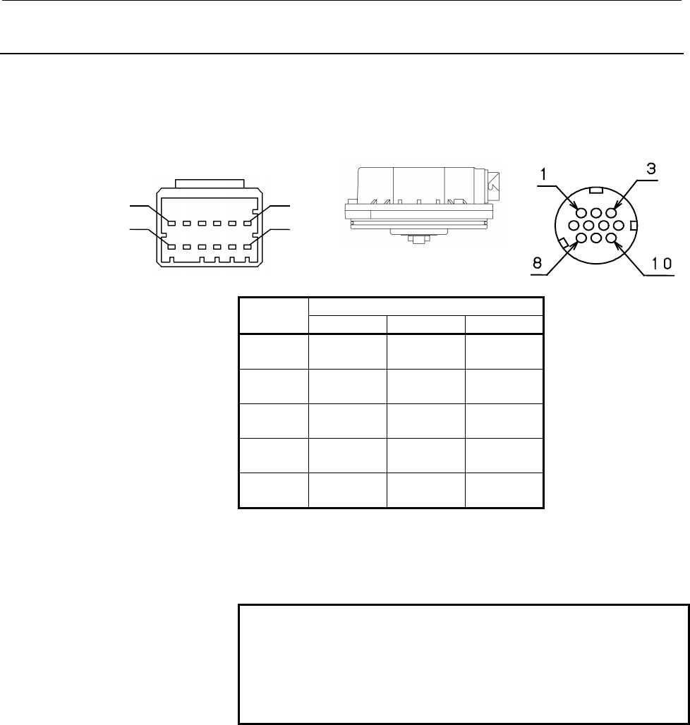
Layout of connector pins
The signals of the βi series Pulsecoder are arranged as follows:
B1 B6
A
1
A
6
β
ββ
β
A64B
→
β
ββ
β64iA, β
ββ
β128iA
Pin No.
Signal
name
β
ββ
βA64B
β
ββ
β64i
A β
ββ
β128iA
SD A4 - -
*SD B4 - -
REQ A3 - -
*REQ B3 - -
RD - 6 6
*RD - 5 5
+5V A2, B2 8,9 8,9
0V A1, B1 7,10 7,10
FG - - 3
+6V A5 4 4
Connector kits
For information on connectors and crimping jigs required for creating
a feedback cable, see Subsec. 2.2.3.
NOTE
If the motor is movable or a flexible cable is
connected to a connector, excessive force may be
applied to the connector. In this case, fix the
feedback cable to prevent the connector from being
broken.
Connecting a Pulsecoder to an amplifier
For cables connecting a Pulsecoder and amplifier, refer to "FANUC
SERVO AMPLIFIER αi series Descriptions (B-65282EN)" and
"FANUC SERVO AMPLIFIER βi series Descriptions (B-65322EN)."
Contents Summary of AC Servo Motor Beta is Descriptions
- Page 1FANUC AC SERVO MOTOR #*s series DESCRIPTIONS B-65302EN/01
- Page 2Ȧ No part of this manual may be reproduced in any form. Ȧ All specifications and designs are subject to change without notice. In this manual we have tried as much as possible to describe all the various matters. However, we cannot describe all the matters which must not be done, or which cannot be
- Page 3B-65302EN/01 SAFETY PRECAUTIONS SAFETY PRECAUTIONS This "Safety Precautions" section describes the precautions which must be observed to ensure safety when using FANUC AC servo motors. Users of any servo motor model are requested to read this "Safety Precautions" carefully before using the servo mot
- Page 4SAFETY PRECAUTIONS B-65302EN/01 1.1 DEFINITION OF WARNING, CAUTION, AND NOTE This manual includes safety precautions for protecting the user and preventing damage to the machine. Precautions are classified into Warning and Caution according to their bearing on safety. Also, supplementary information
- Page 5B-65302EN/01 SAFETY PRECAUTIONS 1.2 WARNING WARNING - Be safely dressed when handling a motor. Wear safety shoes or gloves when handling a motor as you may get hurt on any edge or protrusion on it or electric shocks. - Use a crane or lift to move a motor from one place to another. Motors are heavy.
- Page 6SAFETY PRECAUTIONS B-65302EN/01 WARNING - Connect power wires securely so that they will not get loose. Securely connect power wires and short bars to the terminal block with the specified tightening torque according to the procedures described in this manual. If a motor runs with a wire loosely con
- Page 7B-65302EN/01 SAFETY PRECAUTIONS - Be careful not get your hair or cloths caught in a fan. Be careful especially for a fan used to generate an inward air flow. Be careful also for a fan even when the motor is stopped, because it continues to rotate while the amplifier is turned on. - Ensure that moto
- Page 8SAFETY PRECAUTIONS B-65302EN/01 1.3 CAUTION CAUTION - FANUC motors are designed for use with machines. Do not use them for any other purpose. If a FANUC motor is used for an unintended purpose, it may cause an unexpected symptom or trouble. If you want to use a motor for an unintended purpose, previ
- Page 9B-65302EN/01 SAFETY PRECAUTIONS - Be sure to attach a key to a motor with a keyed shaft. If a motor with a keyed shaft runs with no key attached, it may impair torque transmission or cause imbalance, resulting in the motor being broken. s-7
- Page 10SAFETY PRECAUTIONS B-65302EN/01 1.4 NOTE NOTE - Do not step or sit on a motor. If you step or sit on a motor, it may get deformed or broken. Do not put a motor on another unless they are in packages. - When storing a motor, put it in a dry (non-condensing) place at room temperature (0 to 40 °C). If
- Page 11B-65302EN/01 SAFETY PRECAUTIONS NOTE - Do not apply a commercial power source voltage directly to a motor. Applying a commercial power source voltage directly to a motor may result in its windings being burned. Be sure to use a specified amplifier for supplying voltage to the motor. - For a motor wi
- Page 12
- Page 13B-65302EN/01 PREFACE PREFACE This manual describes the specifications and characteristics of the βis series servo motors. The manual consists of the following chapters: I. Specifications for the βis series This Part provides a general description of the βis series, including how to use the series an
- Page 14PREFACE B-65302EN/01 Related manuals The following seven kinds of manuals are available for FANUC SERVO MOTOR βis series. In the table, this manual is marked with an asterisk (*). Document Document name Major contents Major usage number Specification FANUC AC SERVO MOTOR βis series Characteristics S
- Page 15B-65302EN/01 TABLE OF CONTENTS TABLE OF CONTENTS SAFETY PRECAUTIONS .......................................................................... s-1 PREFACE.................................................................................................. p-1 I. SPECIFICATIONS FOR THE βis SERIES 1 GENE
- Page 16TABLE OF CONTENTS B-65302EN/01 3.2.2 Calculating the Motor Speed ................................................................................. 47 3.2.3 Calculating the load inertia.................................................................................... 48 3.2.4 Calculating the Accele
- Page 17B-65302EN/01 TABLE OF CONTENTS 5.1.1 Types of Pulsecoders and Designation.................................................................. 90 5.1.2 Connecting a Pulsecoder ....................................................................................... 91 5.1.3 Absolute-type Pulsecoder .....
- Page 18
- Page 19I. SPECIFICATIONS FOR THE βis SERIES
- Page 20
- Page 21B-65302EN/01 SPECIFICATIONS FOR THE βiS SERIES 1.GENERAL 1 GENERAL -3-
- Page 221.GENERAL SPECIFICATIONS FOR THE βiS SERIES B-65302EN/01 1.1 FEATURE The FANUC AC servo motor βis series is an AC servo motor suitable for feed axes and peripherals of machine tools, and industrial machines. This servo motor realizes high cost-performance when combined with a small-capacity amplifie
- Page 23B-65302EN/01 SPECIFICATIONS FOR THE βiS SERIES 1.GENERAL 1.2 LINEUP OF THE SERIES The FANUC AC Servo Motor βis series consist of the following series, each of which has the listed characteristics. Torque Series Feature Applications (N⋅⋅m) Feed axes in machine tools High cost-performance model driven
- Page 242.HOW TO USE SERVO MOTORS SPECIFICATIONS FOR THE βiS SERIES B-65302EN/01 2 HOW TO USE SERVO MOTORS This chapter describes the limitation on the environment in which the FANUC AC servo motor βis series is used, how to connect the servo motor to the CNC system, and how to install the servo motor in th
- Page 25B-65302EN/01 SPECIFICATIONS FOR THE βiS SERIES 2.HOW TO USE SERVO MOTORS 2.1 USE ENVIRONMENT FOR SERVO MOTORS 2.1.1 Ambient Environment Ambient temperature The ambient temperature should be 0°C to 40°C. To operate this series in an ambient temperature higher than the above, the use conditions must b
- Page 262.HOW TO USE SERVO MOTORS SPECIFICATIONS FOR THE βiS SERIES B-65302EN/01 Drip-proof environment The level of motor protection is such that a single motor unit can satisfy IP65 of the IEC standard. However, this standard relates only to short-term performance. So, note the following when using the mo
- Page 27B-65302EN/01 SPECIFICATIONS FOR THE βiS SERIES 2.HOW TO USE SERVO MOTORS Oil seal section requirements The motor shaft is sealed to prevent penetration of oil into the motor housing. However, sealing may not be perfect under severe working conditions. When oil bath lubrication is provided for the ge
- Page 282.HOW TO USE SERVO MOTORS SPECIFICATIONS FOR THE βiS SERIES B-65302EN/01 2.1.2 Checking a Delivered Servo Motor and Storing a Servo Motor When the servo motor is delivered, check the following items. • The motor meets the specifications. (Specifications of the model/shaft/sensor) • Damage caused by
- Page 29B-65302EN/01 SPECIFICATIONS FOR THE βiS SERIES 2.HOW TO USE SERVO MOTORS 2.1.3 Separating and Disposing of a Servo Motor For a servo motor, a plastic part is used. Disassemble the motor as shown in the following figure, separate the plastic part (Pulsecoder cover), and dispose of the motor. The foll
- Page 302.HOW TO USE SERVO MOTORS SPECIFICATIONS FOR THE βiS SERIES B-65302EN/01 2.2 CONNECTING A SERVO MOTOR 2.2.1 Applicable Amplifiers The FANUC AC Servo Motor βis series can be driven using FANUC Servo Amplifier αi series or FANUC Servo Amplifier βi series. αi series servo amplifier module (SVM) Motor m
- Page 31B-65302EN/01 SPECIFICATIONS FOR THE βiS SERIES 2.HOW TO USE SERVO MOTORS 2.2.2 Connections Related to a Servo Motor For the FANUC AC Servo Motor βis series, connect the power line of the motor and the signal line of a Pulsecoder to an FANUC Servo Amplifier. When the motor has a built-in brake or coo
- Page 322.HOW TO USE SERVO MOTORS SPECIFICATIONS FOR THE βiS SERIES B-65302EN/01 Connecting the signal line For details of the signal connector on a Pulsecoder, see Subsection I- 5.1.2, "Connecting a Pulsecoder." For details of the connector of a cable connected to a Pulsecoder, see Subsection I-2.2.3, "Con
- Page 33B-65302EN/01 SPECIFICATIONS FOR THE βiS SERIES 2.HOW TO USE SERVO MOTORS 2.2.3 Connector 2.2.3.1 Connectors on the motor side For the FANUC AC Servo Motor βis series, a TÜV-approved connector is used as the power line connector to meet the IEC60034 standard. The power connector for β0.2is and β0.3is
- Page 342.HOW TO USE SERVO MOTORS SPECIFICATIONS FOR THE βiS SERIES B-65302EN/01 CAUTION 1 The motors should be installed with their connector facing downward as long as possible. When it is impossible to install a motor in this position, allow slack in the cable to keep liquids such as a dielectric fluid f
- Page 35B-65302EN/01 SPECIFICATIONS FOR THE βiS SERIES 2.HOW TO USE SERVO MOTORS 2.2.3.2 Connectors on the cable side (for signal : models β0.2is and β0.3is) The signal connector on the cable side for β0.2iS and β0.3iS is not dripproof. To connect the cable, a dedicated crimping tool must be used. Consider
- Page 362.HOW TO USE SERVO MOTORS SPECIFICATIONS FOR THE βiS SERIES B-65302EN/01 2.2.3.3 Connectors on the cable side (for signal : models β0.4is to β22is) The signal connectors on the cable side for β0.4is to β22is are dripproof when engaged with the motor connector. To connect the cable, a dedicated crimp
- Page 37B-65302EN/01 SPECIFICATIONS FOR THE βiS SERIES 2.HOW TO USE SERVO MOTORS The outside dimensions of each type of connector when engaged are shown below: Straight type Elbow type β0.4is to β22is CAUTION 1 In case that the cable is prepared by MTB, total resistance of 5V and 0V must be less than 2Ω. 2
- Page 382.HOW TO USE SERVO MOTORS SPECIFICATIONS FOR THE βiS SERIES B-65302EN/01 2.2.3.4 Connectors on the cable side (for power and brake : models β0.2is and β0.3is) Dedicated connectors which are TÜV approved are available as the connector for power for the β0.2is and β0.3is. The following subsection desc
- Page 39B-65302EN/01 SPECIFICATIONS FOR THE βiS SERIES 2.HOW TO USE SERVO MOTORS 2.2.3.5 Connectors on the cable side (for power and brake : models β0.4is to β1is) Dedicated connectors which are TÜV approved are available as the connector for power for the β0.4is to β1is. The following subsection describes
- Page 402.HOW TO USE SERVO MOTORS SPECIFICATIONS FOR THE βiS SERIES B-65302EN/01 2.2.3.6 Connectors on the cable side (for power and brake : models β2is and β4is) Dedicated connectors which are TÜV approved are available as the connector for power for the β2is and β4is. These connectors differ from the conv
- Page 41B-65302EN/01 SPECIFICATIONS FOR THE βiS SERIES 2.HOW TO USE SERVO MOTORS 2.2.3.7 Connectors on the cable side (for power : models β8is to β22is) To meet the IEC60034 standard, TÜV-approved plug connectors and cable clamps should be used in connecting the power cable. To meet the IEC60034 standard by
- Page 422.HOW TO USE SERVO MOTORS SPECIFICATIONS FOR THE βiS SERIES B-65302EN/01 Specifications of plug connectors on the cable side (support for waterproof IP67, TÜV-approved type) Specifications of Plug Connectors on the Cable Side (Waterproof TÜV-approved Type) [D] Single Block [A] Straight Type [B] Elbo
- Page 43B-65302EN/01 SPECIFICATIONS FOR THE βiS SERIES 2.HOW TO USE SERVO MOTORS Specifications of plug connectors on the cable side (support for waterproof IP67) Specifications of Plug Connectors on the Cable Side (Waterproof Type) [D] Single Block [A] Straight Type [B] Elbow Type Plug Model Name [C] Cable
- Page 442.HOW TO USE SERVO MOTORS SPECIFICATIONS FOR THE βiS SERIES B-65302EN/01 2.2.3.8 Connectors on the cable side (for brake : models β8is to β22is) The models β8is to β22is use a dedicated connector to connect the built-in brake cable. This connector is dripproof. It is connected by soldering, so no sp
- Page 45B-65302EN/01 SPECIFICATIONS FOR THE βiS SERIES 2.HOW TO USE SERVO MOTORS 2.2.3.9 Connection to a conduit hose This section gives information on the specifications of several adapters to be connected that are made by conduit hose manufacturers for reference purposes. Before using an adapter, contact
- Page 462.HOW TO USE SERVO MOTORS SPECIFICATIONS FOR THE βiS SERIES B-65302EN/01 2.3 COUPLING A SERVO MOTOR 2.3.1 Coupling a Servo Motor and Machine In many cases, the following four methods are used for coupling the motor shaft to the ball screw on a machine: Direct connection through a flexible coupling,
- Page 47B-65302EN/01 SPECIFICATIONS FOR THE βiS SERIES 2.HOW TO USE SERVO MOTORS Direct connection using a flexible coupling Direct connection by a flexible coupling has the following advantages over connection using gears: • Even if the angle of the motor shaft to the ball screw changes, it can be compensa
- Page 482.HOW TO USE SERVO MOTORS SPECIFICATIONS FOR THE βiS SERIES B-65302EN/01 Direct connection using a rigid coupling Direct connection using a rigid coupling has the following advantages over direct connection using a flexible coupling: • More economical • The coupling rigidity can be increased. • If t
- Page 49B-65302EN/01 SPECIFICATIONS FOR THE βiS SERIES 2.HOW TO USE SERVO MOTORS Timing belt A timing belt is used in the same cases as gear connection, but in comparison, it has advantages such as low cost and reduced noise during operation, etc. However, it is necessary to correctly understand the charact
- Page 502.HOW TO USE SERVO MOTORS SPECIFICATIONS FOR THE βiS SERIES B-65302EN/01 2.3.2 Allowable Axis Load for a Servo Motor The allowable axis load on a motor shaft is given in the specifications of the relevant motor in Part II and afterward. Using a motor under a load higher than the allowable axial load
- Page 51B-65302EN/01 SPECIFICATIONS FOR THE βiS SERIES 2.HOW TO USE SERVO MOTORS 2.3.3 Axis Run-out Precision of a Servo Motor The axis run-out precision of a servo motor is given in the specifications of the motor in Part II and afterward. The methods of measuring the axis run-out precision are specified b
- Page 522.HOW TO USE SERVO MOTORS SPECIFICATIONS FOR THE βiS SERIES B-65302EN/01 2.3.4 Machine Movement per 1 Revolution of Motor Shaft The machine movement per 1 revolution of motor shaft must be determined at the first stage of machine design referring the load torque, load inertia, rapid traverse speed,
- Page 53B-65302EN/01 SPECIFICATIONS FOR THE βiS SERIES 2.HOW TO USE SERVO MOTORS 2.3.5 Precautions for Using Linear Axis Feedback In the case where the machine moves in a linear direction and movement is directly detected by linear scale such as inductosyn, magne-scale etc., special considerations are neces
- Page 542.HOW TO USE SERVO MOTORS SPECIFICATIONS FOR THE βiS SERIES B-65302EN/01 The above values can be obtained by calculating the elastic deformation for each section of the driving system. The machine should be designed so that the value of this natural frequency [Hz] will be more than or equal to the v
- Page 55B-65302EN/01 SPECIFICATIONS FOR THE βiS SERIES 2.HOW TO USE SERVO MOTORS 2.3.6 Cautions in Mounting a Servo Motor The servo motor contains precision sensor, and is carefully machined and assembled to provide the required precision. Pay attention to the following items to maintain the precision and p
- Page 562.HOW TO USE SERVO MOTORS SPECIFICATIONS FOR THE βiS SERIES B-65302EN/01 A precision sensor is directly connected to the servo motor shaft. Pay attention to the following items to prevent damage to the sensor. • When connecting the power transmission elements such as a gear, a pulley and a coupling
- Page 57B-65302EN/01 SPECIFICATIONS FOR THE βiS SERIES 2.HOW TO USE SERVO MOTORS • When tapping slightly to remove the tightly contacted tapered surface, tap in the radial direction to prevent a shock in the axial direction. • Suppress the rotary unbalance of the connected power transmission element to the
- Page 583.SELECTING A MOTOR SPECIFICATIONS FOR THE βiS SERIES B-65302EN/01 3 SELECTING A MOTOR A servo motor should be selected based on the load on the servo motor, rapid traverse rate, increment system, and other conditions. Motors are subjected to the following types of torque: constant load torque (incl
- Page 59B-65302EN/01 SPECIFICATIONS FOR THE βiS SERIES 3.SELECTING A MOTOR 3.1 CONDITIONS FOR SELECTING A SERVO MOTOR The conditions for selecting a servo motor are given below. [Selection condition 1] Constant load torque - The constant load torque including mechanical friction and gravity must fall within
- Page 603.SELECTING A MOTOR SPECIFICATIONS FOR THE βiS SERIES B-65302EN/01 [Selection condition 4] Acceleration torque - Acceleration can be made with a desired time constant. Since the load torque generally helps deceleration, if acceleration can be executed with a desired time constant, deceleration can b
- Page 61B-65302EN/01 SPECIFICATIONS FOR THE βiS SERIES 3.SELECTING A MOTOR NOTE When handling units, be extremely careful not to use different systems of units. For example, the weight of an object should be expressed in [kg] in the SI system of units because it is handled as "mass" or [kgf] in the gravitat
- Page 623.SELECTING A MOTOR SPECIFICATIONS FOR THE βiS SERIES B-65302EN/01 3.2 SELECTING A MOTOR Sample model for calculations for selecting a servo motor The following subsections explain how to calculate conditions for selecting a servo motor best suited for a table with a horizontal axis with the followi
- Page 63B-65302EN/01 SPECIFICATIONS FOR THE βiS SERIES 3.SELECTING A MOTOR 3.2.1 Calculating the Load Torque When a part moves along an axis at a constant speed, the torque obtained by multiplying the weight of the workpiece driving section by the friction coefficient is always applied. On a vertical or sla
- Page 643.SELECTING A MOTOR SPECIFICATIONS FOR THE βiS SERIES B-65302EN/01 Cautions in calculating the load torque When calculating the torque, take the following precautions: • Allow for the friction torque caused by the gib fastening force (Fg). The torque calculated only from the weight of a movable part
- Page 65B-65302EN/01 SPECIFICATIONS FOR THE βiS SERIES 3.SELECTING A MOTOR 3.2.2 Calculating the Motor Speed Calculate the motor speed using the movable part rapid traverse rate and traveling distance per revolution of the motor and check that the calculated motor speed does not exceed the maximum motor spe
- Page 663.SELECTING A MOTOR SPECIFICATIONS FOR THE βiS SERIES B-65302EN/01 3.2.3 Calculating the load inertia Unlike the load torque, an accurate load inertia can be obtained just by calculation. The inertia of all objects moved by the revolution of a driving motor forms the load inertia of the motor. It do
- Page 67B-65302EN/01 SPECIFICATIONS FOR THE βiS SERIES 3.SELECTING A MOTOR Inertia of a heavy object moving along a straight line (table, workpiece, etc.) SI unit 2 æ l ö 2 J = W ×ç ÷ [ kg ⋅ m ] w è 2π ø W : Weight of the object moving along a straight line [kg] l : Traveling distance along a straight line
- Page 683.SELECTING A MOTOR SPECIFICATIONS FOR THE βiS SERIES B-65302EN/01 Inertia of a cylindrical object in which the center of rotation is displaced Center of rotation 2 J = J 0 + MR J0 : Inertia around the center of the object M : Weight of the object R : Radius of rotation The above equation is used to
- Page 69B-65302EN/01 SPECIFICATIONS FOR THE βiS SERIES 3.SELECTING A MOTOR [Example of calculation for condition 3] Load inertial ratio In this example, the sum of Jb and Jw obtained above is the load inertia (JL). JL = 0.00030 + 0.00304 = 0.00334 [kg⋅m2] The motor inertial of the β8/3000is is 0.00117 [kg⋅m
- Page 703.SELECTING A MOTOR SPECIFICATIONS FOR THE βiS SERIES B-65302EN/01 3.2.4 Calculating the Acceleration Torque Calculate the acceleration torque required for the motor to accelerate and then obtain the torque required for acceleration by calculating the total torque including the constant load torque
- Page 71B-65302EN/01 SPECIFICATIONS FOR THE βiS SERIES 3.SELECTING A MOTOR [Example of calculation for condition 4-1] Example of calculation Try to perform linear acceleration/deceleration under the following condition. Vm=3000 [min-1] ta=0.1 [s] ks=30 [s-1] JL=0.00334 [kg⋅m2] Select the β8/3000is provision
- Page 723.SELECTING A MOTOR SPECIFICATIONS FOR THE βiS SERIES B-65302EN/01 2π 1 Ta = Vm × × × (J M + J L /ηη 60 t1 t2 Vr = Vm × ( 1 − ) 2t 1 2π 1 Acc a = Vm × × × P 60 t1 Ta : Acceleration torque [N⋅m] Vm : Motor speed in rapid traverse [min-1] t1 : Acceleration time constant T1 [sec] t2 : Acceleration time
- Page 73B-65302EN/01 SPECIFICATIONS FOR THE βiS SERIES 3.SELECTING A MOTOR 3.2.4.2 Calculating the torque required by the motor shaft in acceleration To obtain the torque required by the motor shaft (T), add the constant load torque (Tm) to the acceleration torque (Ta). T = Ta + Tm T : Torque required by th
- Page 743.SELECTING A MOTOR SPECIFICATIONS FOR THE βiS SERIES B-65302EN/01 The speed-torque characteristics of the β12/3000is, given below, show that the point of 19.3 [N⋅m]/2050 [min-1] is within the intermittent operating zone of the β12/3000is (acceleration is possible). Speed - torque characteristics 30
- Page 75B-65302EN/01 SPECIFICATIONS FOR THE βiS SERIES 3.SELECTING A MOTOR 3.2.5 Calculating the Root-mean-square Value of the Torques A motor gets hot in proportion to the square of the torque. For a servo motor for which the load condition always changes, the calculated root-mean-square value of torque in
- Page 763.SELECTING A MOTOR SPECIFICATIONS FOR THE βiS SERIES B-65302EN/01 [Example of calculation for condition 5] Root-mean-square value of the torques β12/3000is ( Ts = 1.4 [N⋅m] ), Ta = 17.9 [N⋅m], Tm = To = 1.4 [N⋅m], t1 = 0.1 [sec], t2 = 2.0 [sec], t3 = 3.0 [sec] Trms = (17.9 + 1.4) 2 × 0.1 + 1.4 2 ×
- Page 77B-65302EN/01 SPECIFICATIONS FOR THE βiS SERIES 3.SELECTING A MOTOR 3.2.6 Calculating the Percentage Duty Cycle and ON Time with the Maximum Cutting Torque Confirm that the time (duty percentage and ON time) during which the maximum cutting torque can be applied for cutting is shorter than the desire
- Page 783.SELECTING A MOTOR SPECIFICATIONS FOR THE βiS SERIES B-65302EN/01 Calculating the percentage duty cycle with the maximum cutting torque Torque Maximum cutting torque (Tms) Time If the load torque (Tms) is greater than the product of the motor stall torque (Ts) and thermal efficiency (α), calculate
- Page 79B-65302EN/01 SPECIFICATIONS FOR THE βiS SERIES 3.SELECTING A MOTOR 3.2.7 Calculating the Dynamic Brake Stop Distance The equation for calculating the coasting distance when an abnormality occurs and the machine tool is stopped by dynamic braking with both ends of the motor power line shorted (dynami
- Page 803.SELECTING A MOTOR SPECIFICATIONS FOR THE βiS SERIES B-65302EN/01 [Example of calculation for condition 7] Dynamic brake stop distance Assume that the desired stop distance is 150 mm. Coasting distance = (3000/60×20)[mm/sec]×0.05[sec]+(0.00228[kg⋅m2]+ 0.00334[kg⋅m2])×(4.0×10-2×3000[min-1]+3.1×10⁻⁹×
- Page 81B-65302EN/01 SPECIFICATIONS FOR THE βiS SERIES 3.SELECTING A MOTOR Coefficients for dynamic brake calculation When an αis/β is series servo amplifier (SVM) is used Gravitational system of SI unit Model units A B A B -7 -1 -8 β0.2/5000iS 8.3 5.3×10 8.1×10 5.7×10 -7 -1 -8 β0.3/5000iS 3.4 4.6×10 3.4×10
- Page 823.SELECTING A MOTOR SPECIFICATIONS FOR THE βiS SERIES B-65302EN/01 3.3 HOW TO FILL IN THE SERVO MOTOR SELECTION DATA TABLE Select a suitable motor according to load conditions, rapid traverse rate, increment system and other factors. To aid in selecting the correct motor, we recommend filling in the
- Page 83B-65302EN/01 SPECIFICATIONS FOR THE βiS SERIES 3.SELECTING A MOTOR Servo Motor Selection Data Table SI unit User name Kind of machine tool CNC equipment Type of machine tool Spindle motor Item Axis Specifications of moving object * Weight of moving object (including workpiece, etc.) kg * Axis moveme
- Page 843.SELECTING A MOTOR SPECIFICATIONS FOR THE βiS SERIES B-65302EN/01 Servo Motor Selection Data Table Gravitational system of units User name Kind of machine tool CNC equipment Type of machine tool Spindle motor Item Axis Specifications of moving object * Weight of moving object (including workpiece,
- Page 85B-65302EN/01 SPECIFICATIONS FOR THE βiS SERIES 3.SELECTING A MOTOR 3.3.2 Explanation of Items 3.3.2.1 Title User name Fill in this blank with the name of the user. Kind of machine tool Fill in this blank with a general name of machine tools, such as lathe, milling machine, machining center, and othe
- Page 863.SELECTING A MOTOR SPECIFICATIONS FOR THE βiS SERIES B-65302EN/01 3.3.2.2 Specifications of moving object Be sure to enter data in this row. Data entered here is needed for determining the approximate motor load conditions (inertia, load torque). - Mass(weight) of driven parts Enter the mass(weight
- Page 87B-65302EN/01 SPECIFICATIONS FOR THE βiS SERIES 3.SELECTING A MOTOR - Machine tool efficiency This value is used for calculating the transfer efficiency of motor output on a machine tool. Standard value is 0.9. Generally, a drop in transfer efficiency is expected if a reduction gear having a large de
- Page 883.SELECTING A MOTOR SPECIFICATIONS FOR THE βiS SERIES B-65302EN/01 3.3.2.3 Mechanical specifications Enter basic data that is required for selecting the motor. For details on how to calculate each of the items, see Section 3.2. - Movement per rotation of motor Enter the movement of the machine tool
- Page 89B-65302EN/01 SPECIFICATIONS FOR THE βiS SERIES 3.SELECTING A MOTOR - Steady-state load torque Enter the torque obtained by calculating the force applied for moving the machine tool and state-state components such as friction (including holding torque in the case of a gravity shaft) reflected on the
- Page 903.SELECTING A MOTOR SPECIFICATIONS FOR THE βiS SERIES B-65302EN/01 - Positioning distance Enter the distance as a condition required for calculating the rapid traverse positioning frequency. When an exclusive positioning device is used, enter this value together with the desired positioning time bel
- Page 91B-65302EN/01 SPECIFICATIONS FOR THE βiS SERIES 3.SELECTING A MOTOR 3.3.2.4 Motor specifications and characteristics - Motor type Enter the motor type, if desired. - Pulsecoder Enter the specifications (absolute, number of pulses: 65,536 or 131,072) of the feedback sensor (Pulsecoder) built into the
- Page 923.SELECTING A MOTOR SPECIFICATIONS FOR THE βiS SERIES B-65302EN/01 bell-shaped acceleration/deceleration. Enter te only for the time constant in cutting feed. Exponential acceleration/deceleration Speed Vm 0.632Vm te te Time te : time - Position loop gain Fill in this blank with a value which is con
- Page 93B-65302EN/01 SPECIFICATIONS FOR THE βiS SERIES 3.SELECTING A MOTOR 3.4 CHARACTERISTIC CURVE AND DATA SHEET Performance of each motor model is represented by characteristic curves and data sheet shown below, which are given in Part II. 3.4.1 Performance Curves The characteristic curves representing t
- Page 943.SELECTING A MOTOR SPECIFICATIONS FOR THE βiS SERIES B-65302EN/01 Overload duty characteristic The percentage duty cycle indicates the ratio of the time during which torque can be applied to the total time of a single cycle. The ON time indicates the time during which the torque is being applied. O
- Page 95B-65302EN/01 SPECIFICATIONS FOR THE βiS SERIES 3.SELECTING A MOTOR The duty calculation procedure is shown below: <1> Calculate Torque percent by formula (b) below. <2> Motor can be operated at any point on and inside the curve (according to the limits by overheating or overcurrent alarms) correspon
- Page 963.SELECTING A MOTOR SPECIFICATIONS FOR THE βiS SERIES B-65302EN/01 3.4.2 Data Sheet The data sheet gives the values of motor parameters relating to the performance. The values of parameters are those under the following conditions. • The ambient temperature for the motor is 20°C. • The error is ±10%
- Page 97B-65302EN/01 SPECIFICATIONS FOR THE βiS SERIES 3.SELECTING A MOTOR Torque constant : Kt [N⋅⋅m/Arms] [kgf⋅⋅cm/Arms] This is known as torque sensitivity and represents the torque developed per ampere of phase current. This value is a motor-specific constant, and is calculated by the flux distribution
- Page 983.SELECTING A MOTOR SPECIFICATIONS FOR THE βiS SERIES B-65302EN/01 Mass : w [kg] This is the mass of the motor. The masses of the motor with brakes and that without brakes are indicated. Maximum current of applicable servo amplifiers Applicable servo amplifier modules are briefly described. For more
- Page 99B-65302EN/01 SPECIFICATIONS FOR THE βiS SERIES 4.CONDITIONS FOR APPROVAL RELATED TO THE IEC60034 STANDARD 4 CONDITIONS FOR APPROVAL RELATED TO THE IEC60034 STANDARD This chapter describes the conditions the following FANUC βis series AC servo motors must clear before they can be approved for the IEC
- Page 1004.CONDITIONS FOR APPROVAL RELATED TO THE IEC60034 STANDARD SPECIFICATIONS FOR THE βiS SERIES B-65302EN/01 4.1 TYPES OF MOTORS TO BE APPROVED The following FANUC AC Servo Motor βis series can comply with the IEC60034 standard if you follow the descriptions in this chapter. The FANUC AC Servo Motor βi
- Page 101B-65302EN/01 SPECIFICATIONS FOR THE βiS SERIES 4.CONDITIONS FOR APPROVAL RELATED TO THE IEC60034 STANDARD 4.2 APPROVED SPECIFICATIONS The following specifications are approved for the IEC60034 standard. 4.2.1 Motor Speed (IEC60034-1) The "rated-output speed" and "allowable maximum speed" are given o
- Page 1024.CONDITIONS FOR APPROVAL RELATED TO THE IEC60034 STANDARD SPECIFICATIONS FOR THE βiS SERIES B-65302EN/01 4.2.3 Protection Type (IEC60034-5) Motor protection confirms to IP65. The Pulsecoder connector is waterproof when engaged. IP6x: Completely dust-proof machine This structure completely prevents
- Page 103B-65302EN/01 SPECIFICATIONS FOR THE βiS SERIES 4.CONDITIONS FOR APPROVAL RELATED TO THE IEC60034 STANDARD 4.2.6 Heat Protection (IEC60034-11) The heat protection type is as listed below: TP211 1 : Temperature rise limit category 1 for heat protection 1 : Stop only at stage 1 (no warning) 2 : Protect
- Page 1044.CONDITIONS FOR APPROVAL RELATED TO THE IEC60034 STANDARD SPECIFICATIONS FOR THE βiS SERIES B-65302EN/01 4.3 CONNECTORS REQUIRED FOR APPROVAL 4.3.1 Power Line Connectors (for Models β0.2iS and β0.3iS) The motor power line must be connected using the following specified connectors. Dedicated Specifi
- Page 105B-65302EN/01 SPECIFICATIONS FOR THE βiS SERIES 4.CONDITIONS FOR APPROVAL RELATED TO THE IEC60034 STANDARD 4.3.3 Power Line Connectors (for Models β2iS and β4iS) The motor power line must be connected using the following specified connectors. Dedicated Specification Model Name Tools Manufacture (Manu
- Page 1064.CONDITIONS FOR APPROVAL RELATED TO THE IEC60034 STANDARD SPECIFICATIONS FOR THE βiS SERIES B-65302EN/01 4.3.4 Power Line Connectors (for Models β8iS to β22iS) The motor power cable must be connected using the connectors and cable clamps specified below. Motor Cable clamp Connector model Plug conne
- Page 107B-65302EN/01 SPECIFICATIONS FOR THE βiS SERIES 5.FEEDBACK SENSOR 5 FEEDBACK SENSOR All AC servo motors contain a Pulsecoder (optical encoder) as a feedback sensor which detects position and velocity. Separate type position sensors are also available for detecting a position by attaching directly to
- Page 1085.FEEDBACK SENSOR SPECIFICATIONS FOR THE βiS SERIES B-65302EN/01 5.1 PULSECODER All AC servo motors feature a Pulsecoder (optical encoder). The Pulsecoder outputs position information and an alarm signal. The outline drawing of a Pulsecoder is not given in this section because it is contained in a m
- Page 109B-65302EN/01 SPECIFICATIONS FOR THE βiS SERIES 5.FEEDBACK SENSOR 5.1.2 Connecting a Pulsecoder Layout of connector pins The signals of the βi series Pulsecoder are arranged as follows: βA64B β64iA, β128iA B1 B6 → A1 A6 Signal Pin No. name β A64B β 64iA β 128iA SD A4 - - *SD B4 - - REQ A3 - - *REQ B3
- Page 1105.FEEDBACK SENSOR SPECIFICATIONS FOR THE βiS SERIES B-65302EN/01 5.1.3 Absolute-type Pulsecoder When the NC is turned off, the Pulsecoder position detection function is backed up by battery. So, when the NC is next turned on, the operator does not have to perform reference position return. For backu
- Page 111B-65302EN/01 SPECIFICATIONS FOR THE βiS SERIES 5.FEEDBACK SENSOR 5.2 SEPARATE PULSECODER For detecting a position by attaching directly to a ball screw or a machine, use a separate Pulsecoder. 5.2.1 Separate Pulsecoder Type and Designation Separate Pulsecoder are available. Features and rapid traver
- Page 1125.FEEDBACK SENSOR SPECIFICATIONS FOR THE βiS SERIES B-65302EN/01 5.2.3 Connecting a Separate Type Pulsecoder The layout of connector pins is shown below. For the connection diagram for separate type Pulsecoders, refer to the relevant NC connection manual. Layout of Connector Pins of Pulsecoder αA100
- Page 113B-65302EN/01 SPECIFICATIONS FOR THE βiS SERIES 5.FEEDBACK SENSOR 5.2.4 Outline Drawings of Separate Pulsecoder MS connector : MS3102A-20-29P Fig.5.2.4 Pulsecoder αA1000S - 95 -
- Page 1145.FEEDBACK SENSOR SPECIFICATIONS FOR THE βiS SERIES B-65302EN/01 5.2.5 Cautions in Using a Separate Type Pulsecoder Pay attention to the following items when using the separate Pulsecoder. • Increase the machine rigidity between the servo motor and the Pulsecoder to minimize mechanical vibration. If
- Page 115B-65302EN/01 SPECIFICATIONS FOR THE βiS SERIES 6.BUILT-IN BRAKE 6 BUILT-IN BRAKE Some models of the AC servo motor βis series use motors that contain a holding brake to prevent falling along a vertical axis. This chapter explains the specifications of built-in brakes and gives cautions. The motor wi
- Page 1166.BUILT-IN BRAKE SPECIFICATIONS FOR THE βiS SERIES B-65302EN/01 6.1 BRAKE SPECIFICATIONS The specifications of built-in brakes are listed below. β 0.2iS β 0.4iS β 2iS β 8iS Motor model Unit β 1iS β 22iS β 0.3iS β 0.5iS β 4iS β 12iS Nm 0.32 0.65 1.2 3 8 35 Brake torque kgf·cm 3.3 6.6 12 31 82 357 Res
- Page 117B-65302EN/01 SPECIFICATIONS FOR THE βiS SERIES 6.BUILT-IN BRAKE 6.2 CONNECTING A BRAKE 6.2.1 Layout of Connector Pins The following shows the shape and pin arrangement of the brake connectors. Models β0.2is and β0.3is B1 B2 B3 A1 A2 A3 Connections: B2=BK, B3=BK (Connect to inside of power connector.
- Page 1186.BUILT-IN BRAKE SPECIFICATIONS FOR THE βiS SERIES B-65302EN/01 Models β8is to β22is Connections: 1=BK, 2=BK, 3=NC(Not Connected), 4=GND(Note) * BK indicates a power supply (24 VDC, 0 VDC) for the brake. The brake is nonpolarized. NOTE Since pin 4 is connected to the brake cabinet, it can be used wh
- Page 119B-65302EN/01 SPECIFICATIONS FOR THE βiS SERIES 6.BUILT-IN BRAKE 6.2.2 Connection of the Brakes Configure a brake circuit by referencing the following brake connection diagrams and the recommended parts shown in the following section. To other 24 VDC peripheral devices (such as a relay and solenoid)
- Page 1206.BUILT-IN BRAKE SPECIFICATIONS FOR THE βiS SERIES B-65302EN/01 6.2.3 Recommended Parts in Brake Circuits The following table lists the recommended parts to be used as components of a brake circuit and their specifications. All models of the β is series FANUC Name of Name Model No. Specifications Pr
- Page 121B-65302EN/01 SPECIFICATIONS FOR THE βiS SERIES 6.BUILT-IN BRAKE 6.3 CAUTIONS Pay attention to the following points when motors with built-in brakes are used. 1 A built-in brake is used as a holding brake to prevent falling along an axis at servo off. This brake functions as a brake at an emergency s
- Page 1226.BUILT-IN BRAKE SPECIFICATIONS FOR THE βiS SERIES B-65302EN/01 6.4 REDUCING THE BRAKE SHAFT FALL AMOUNT During use of a motor with a brake, the amount of falling along an axis at a power failure or emergency stop, or when the CNC power supply is turned off during excitation of the motor may become
- Page 123II. FANUC AC SERVO MOTOR βiS SERIES
- Page 124
- Page 125B-65302EN/01 FANUC AC SERVO MOTOR βiS 1.TYPES OF MOTORS AND DESIGNATION 1 TYPES OF MOTORS AND DESIGNATION The types and specifications of βiS series servo motors are described as follows. Models β0.2/5000iS and β0.3/5000iS A06B-011x-By0z x 1 : Model β0.2/5000iS 2 : Model β0.3/5000iS y 1 : Straight s
- Page 1261.TYPES OF MOTORS AND DESIGNATION FANUC AC SERVO MOTOR βiS SERIES B-65302EN/01 Models β2/4000iS, β4/4000iS, β8/3000iS, β12/3000iS, and β22/2000iS A06B-00xx-By0z xx 61 : Model β2/4000iS 63 : Model β4/4000iS 75 : Model β8/3000iS 78 : Model β12/3000iS 85 : Model β22/2000iS y 0 : Taper shaft 1 : Straigh
- Page 127B-65302EN/01 FANUC AC SERVO MOTOR βiS SERIES 2.SPECIFICATIONS AND CHARACTERISTICS 2 SPECIFICATIONS AND CHARACTERISTICS This chapter describes the specifications and characteristics of FANUC AC servo motor βiS series. First section describes the common specifications to all motors, and next section d
- Page 1282.SPECIFICATIONS AND CHARACTERISTICS FANUC AC SERVO MOTOR βiS SERIES B-65302EN/01 2.1 COMMON SPECIFICATIONS This section describes the common specifications to FANUC AC servo motor βiS series. Common specifications • Ambient temperature : 0 to 40°C • Ambient humidity : 80%RH or less (no dew) • Insta
- Page 129B-65302EN/01 FANUC AC SERVO MOTOR βiS SERIES 2.SPECIFICATIONS AND CHARACTERISTICS Shaft runout precision Shaft dia. Rabbet dia. Mounting face Motor Model runout eccentricity runout β0.2/5000iS Max. 0.02mm Max. 0.04mm Max. 0.06mm β0.3/5000iS β0.4/5000iS β0.5/5000iS Max. 0.02mm Max. 0.04mm Max. 0.06mm
- Page 1302.SPECIFICATIONS AND CHARACTERISTICS FANUC AC SERVO MOTOR βiS SERIES B-65302EN/01 2.2 CHARACTERISTIC CURVE AND DATA SHEET This section describes the individual specifications and characteristics of FANUC AC servo motor βiS series.in the form of data sheet. For details on these items, refer to "I-3.4
- Page 131B-65302EN/01 FANUC AC SERVO MOTOR βiS SERIES 2.SPECIFICATIONS AND CHARACTERISTICS Model #0.2/5000*s Specification A06B-0111-B□0□ Speed-Torque Characteristics Over Load Duty 0.6 100 90 0.5 110% 80 0.4 70 120% Torque (Nm) Duty (time%) Intermitting Operation 60 130% 0.3 50 140% 40 150% 0.2 170% 30 210%
- Page 1322.SPECIFICATIONS AND CHARACTERISTICS FANUC AC SERVO MOTOR βiS SERIES B-65302EN/01 Model #0.3/5000*s Specification A06B-0112-B□0□ Speed-Torque Characteristics Over Load Duty 1.2 100 90 1 110% 80 0.8 70 120% Torque (Nm) Duty (time%) Intermitting Operation 60 130% 0.6 50 140% 40 150% 0.4 170% 30 210% 0
- Page 133B-65302EN/01 FANUC AC SERVO MOTOR βiS SERIES 2.SPECIFICATIONS AND CHARACTERISTICS Model #0.4/5000*s Specification A06B-0114-B□0□ Speed-Torque Characteristics Over Load Duty 1.2 100 90 110% 1 80 120% 0.8 70 Torque (Nm) Duty (time%) Intermitting 60 130% Operation 0.6 140% 50 150% 40 170% 0.4 30 210% 0
- Page 1342.SPECIFICATIONS AND CHARACTERISTICS FANUC AC SERVO MOTOR βiS SERIES B-65302EN/01 Model #0.5/5000*s Specification A06B-0115-B□0□ Speed-Torque Characteristics Over Load Duty 3 100 90 110% 2.5 80 120% 2 70 Torque (Nm) Duty (time%) Intermitting 130% Operation 60 1.5 140% 50 150% 40 170% 1 30 210% 0.5 2
- Page 135B-65302EN/01 FANUC AC SERVO MOTOR βiS SERIES 2.SPECIFICATIONS AND CHARACTERISTICS Model #1/5000*s Specification A06B-0116-B□0□ Speed-Torque Characteristics Over Load Duty 6 100 90 110% 5 80 120% 4 70 Torque (Nm) Duty (time%) Intermitting 130% Operation 60 3 140% 50 150% 40 170% 2 30 210% 1 20 Contin
- Page 1362.SPECIFICATIONS AND CHARACTERISTICS FANUC AC SERVO MOTOR βiS SERIES B-65302EN/01 Model #2/4000*s Specification A06B-0061-B□0□ Speed-Torque Characteristics Over Load Duty 8 100 7 90 110% 80 6 120% 70 Torque (Nm) Duty (time%) 5 Intermitting 130% Operation 60 140% 4 50 150% 3 40 170% 30 2 210% 20 1 Co
- Page 137B-65302EN/01 FANUC AC SERVO MOTOR βiS SERIES 2.SPECIFICATIONS AND CHARACTERISTICS Model #4/4000*s Specification A06B-0063-B□0□ Speed-Torque Characteristics Over Load Duty 12 100 90 110% 10 80 120% 70 8 Torque (Nm) Duty (time%) Intermitting 130% Operation 60 140% 6 50 150% 40 170% 4 30 210% 20 2 Cont
- Page 1382.SPECIFICATIONS AND CHARACTERISTICS FANUC AC SERVO MOTOR βiS SERIES B-65302EN/01 Model #8/3000*s Specification A06B-0075-B□0□ Speed-Torque Characteristics Over Load Duty 16 100 14 90 110% 80 12 120% 70 Torque (Nm) Duty (time%) 10 Intermitting 130% Operation 60 140% 8 50 150% 6 40 170% 30 4 210% 20
- Page 139B-65302EN/01 FANUC AC SERVO MOTOR βiS SERIES 2.SPECIFICATIONS AND CHARACTERISTICS Model #12/3000*s Specification A06B-0078-B□0□ Speed-Torque Characteristics Over Load Duty 30 100 90 110% 25 80 120% 70 20 Torque (Nm) Duty (time%) Intermitting 130% Operation 60 140% 15 50 150% 40 170% 10 30 210% 20 5
- Page 1402.SPECIFICATIONS AND CHARACTERISTICS FANUC AC SERVO MOTOR βiS SERIES B-65302EN/01 Model #22/2000*s Specification A06B-0085-B□0□ Speed-Torque Characteristics Over Load Duty 50 100 45 90 110% 40 80 120% 35 70 Torque (Nm) Duty (time%) Intermitting 130% 30 Operation 60 140% 25 50 150% 20 40 170% 15 30 2
- Page 141B-65302EN/01 FANUC AC SERVO MOTOR βiS SERIES 3.OUTLINE DRAWINGS 3 OUTLINE DRAWINGS This chapter describes the outline drawings of FANUC AC servo motor βiS series. The drawings are follows. Model Fig. No. Models β0.2iS and β0.3iS Fig. 3(a) Models β0.2iS and β0.3iS (with brake) Fig. 3(b) Models β0.2iS
- Page 1423.OUTLINE DRAWINGS FANUC AC SERVO MOTOR βiS SERIES B-65302EN/01 Fig. 3(a) Models β0.2iS and β0.3iS - 124 -
- Page 143B-65302EN/01 FANUC AC SERVO MOTOR βiS SERIES 3.OUTLINE DRAWINGS Fig. 3(b) Models β0.2iS and β0.3iS (with brake) - 125 -
- Page 1443.OUTLINE DRAWINGS FANUC AC SERVO MOTOR βiS SERIES B-65302EN/01 Fig. 3(c) Models β0.2iS and β0.3iS (shaft option) - 126 -
- Page 145B-65302EN/01 FANUC AC SERVO MOTOR βiS SERIES 3.OUTLINE DRAWINGS Fig. 3(d) Models β0.4iS, β0.5iS, and β1iS - 127 -
- Page 1463.OUTLINE DRAWINGS FANUC AC SERVO MOTOR βiS SERIES B-65302EN/01 Fig. 3(e) Models β0.4iS, β0.5iS, and β1iS (with brake) - 128 -
- Page 147B-65302EN/01 FANUC AC SERVO MOTOR βiS SERIES 3.OUTLINE DRAWINGS Fig. 3(f) Models β0.4iS and β0.5iS (shaft option) - 129 -
- Page 1483.OUTLINE DRAWINGS FANUC AC SERVO MOTOR βiS SERIES B-65302EN/01 Fig. 3(g) Model β1iS (shaft option) - 130 -
- Page 149B-65302EN/01 FANUC AC SERVO MOTOR βiS SERIES 3.OUTLINE DRAWINGS Fig. 3(h) Models β0.4iS, β0.5iS, and β1iS (engaged with the connector) (elbow type) - 131 -
- Page 1503.OUTLINE DRAWINGS FANUC AC SERVO MOTOR βiS SERIES B-65302EN/01 Fig. 3(i) Models β0.4iS, β0.5iS, and β1iS (engaged with the connector) (straight type) - 132 -
- Page 151B-65302EN/01 FANUC AC SERVO MOTOR βiS SERIES 3.OUTLINE DRAWINGS Fig. 3(j) Models β2iS and β4iS - 133 -
- Page 1523.OUTLINE DRAWINGS FANUC AC SERVO MOTOR βiS SERIES B-65302EN/01 Fig. 3(k) Models β2iS and β4iS (with brake) - 134 -
- Page 153B-65302EN/01 FANUC AC SERVO MOTOR βiS SERIES 3.OUTLINE DRAWINGS Fig. 3(l) Model β2iS (shaft option) - 135 -
- Page 1543.OUTLINE DRAWINGS FANUC AC SERVO MOTOR βiS SERIES B-65302EN/01 Fig. 3(m) Model β4iS (shaft option) - 136 -
- Page 155B-65302EN/01 FANUC AC SERVO MOTOR βiS SERIES 3.OUTLINE DRAWINGS Fig. 3(n) Models β8iS and β12iS - 137 -
- Page 1563.OUTLINE DRAWINGS FANUC AC SERVO MOTOR βiS SERIES B-65302EN/01 Fig. 3(o) Models β8iS and β12iS (with brake) - 138 -
- Page 157B-65302EN/01 FANUC AC SERVO MOTOR βiS SERIES 3.OUTLINE DRAWINGS Fig. 3(p) Model β8iS (shaft option) - 139 -
- Page 1583.OUTLINE DRAWINGS FANUC AC SERVO MOTOR βiS SERIES B-65302EN/01 Fig. 3(q) Model β12iS (shaft option) - 140 -
- Page 159B-65302EN/01 FANUC AC SERVO MOTOR βiS SERIES 3.OUTLINE DRAWINGS Fig. 3(r) Model β22iS - 141 -
- Page 1603.OUTLINE DRAWINGS FANUC AC SERVO MOTOR βiS SERIES B-65302EN/01 Fig. 3(s) Model β22iS (with brake) - 142 -
- Page 161B-65302EN/01 FANUC AC SERVO MOTOR βiS SERIES 3.OUTLINE DRAWINGS Fig. 3(t) Model β22iS (shaft option) - 143 -
- Page 1624.CONNECTION OF POWER LINE FANUC AC SERVO MOTOR βiS SERIES B-65302EN/01 4 CONNECTION OF POWER LINE This chapter describes the connecting table of the motor side of the motor power line. Other connectiong table for using the motor, refer to "I-2.2.2 Connection of servo motor". Models β0.2/5000iS and
- Page 163B-65302EN/01 FANUC AC SERVO MOTOR βiS SERIES 4.CONNECTION OF POWER LINE Models β8/3000iS and β12/3000iS A B C Grounding plate D Motor body Model β22/2000iS A B C Grounding plate D Motor body WARNING When attaching the power leads and jumpers to the terminal block, follow the procedure described in t
- Page 164
- Page 165B-65302EN/01 INDEX INDEX Connector ....................................................................... 15 Connectors on the cable side Absolute-type Pulsecoder ............................................... 92 (for brake : models β8is to β22is) ............................ 26 Allowable Axis
- Page 166INDEX B-65302EN/01 Mechanical specifications............................................... 70 Motor specifications and characteristics ......................... 73 Motor Speed (IEC60034-1)............................................ 83 Mounting Method (IEC60034-7) ..................................
- Page 167Revision Record FANUC AC SERVO MOTOR βis series DESCRIPTIONS (B-65302EN) 01 May, 2003 Edition Date Contents Edition Date Contents
- Page 168
- Page 169FANUC AC SERVO MOTOR αis/αi series DESCRIPTIONS FANUC AC SERVO MOTOR βis series DESCRIPTIONS High speed AC Servo motor for live tool 1. Type of applied technical documents FANUC AC SERVO MOTOR αis/αi series DESCRIPTIONS Name FANUC AC SERVO MOTOR βis series DESCRIPTIONS Spec. No. /Version B-65262EN/0
- Page 170FANUC AC SERVO MOTOR α s/α i series DESCRIPTIONS FANUC AC SERVO MOTOR β is series DESCRIPTIONS High speed AC Servo motor for live tool 1. Type of applied technical documents FANUC AC SERVO MOTOR α is /α i series DESCRIPTIONS Name FANUC AC SERVO MOTOR β is series DESCRIPTIONS Spec. No. /Version B-652
- Page 1711. GENERAL l High speed servo motors for live tool 1.Extention of motor speed. (Change of parameter) β0.5/6000 iS (Conventional model name: β0.5/5000 iS) β1/6000 iS (Conventional model name: β1/5000 iS) Conventional motor New motor Conventional speed Speed up Model name β0.5/5000 iS β0.5/6000 iS β0.
- Page 1722. TYPE OF MOTORS AND DESIGNATION Models β 0.5/6000iS β 1/6000iS A06B-01xx -By0z xx 15 : Model β0.5/6000iS 16 : Model β1/6000iS y 1 : Straight shaft 4 : Straight shaft with the 24VDC brake z 3 : Pulsecoder β64iA Models α 2/6000iS α 2/6000HViS α 8/6000iS α 8/6000HViS A06B-02xx-By0z xx 18 : Model α2/6
- Page 1733. CHARACTERISTICS CURVE AND DATA SHEET β0.5/6000iS page 5 β1/6000iS page 6 α2/6000iS page 7 α8/6000iS page 8 α2/6000HViS page 9 α8/6000HViS page 10 4. OUTLINE DRAWINGS Model Fig. No. Models β0.5iS and β1iS Fig.4(a) Models β0.5iS and β1iS (with brake) Fig.4(b) Model β0.5iS (shaft option) Fig.4(c) Mo
- Page 1746. Coefficients for calculating the dynamic brake stopping distance SI unit Motor Model A B Jm(kgm2 ) β0.5/6000iS 9.1E-01 2.1E-07 0.000018 β1/6000iS 3.8E-01 8.8E-08 0.000034 α2/6000iS 2.9E-01 1.3E-07 0.000291 α8/6000iS 4.2E-01 4.4E-09 0.00117 α2/6000HViS 5.9E-01 6.7E-08 0.000291 α8/6000HViS 3.2E-01
- Page 175Model β 0. 5/6000i s Specification A06B-0115-? 0? Speed-Torque Characteristics Over Load Duty 3 100 90 110% 2.5 80 120% 70 Torque [Nm] 2 130% Duty[%] Interm itting 60 140% Operating 50 1.5 150% 40 170% 1 30 210% 20 0.5 MAX Continuous 10 Operating 0 0 10000 10 100 1000 1 0 1000 2000 3000 4000 5000 60
- Page 176Model β 1/6000 i s Specification A06B-0116-? 0? Speed-Torque Characteristics Over Load Duty 6 100 90 110% 5 80 120% 70 Torque [Nm] 4 Duty[%] 130% Interm itting 60 140% Operating 50 3 150% 40 170% 2 30 210% 20 1 10 MAX Continuous Operating 0 100000 100 1000 10000 0 1 10 0 1000 2000 3000 4000 5000 600
- Page 177Model α2/6000i s Specification A06B-0218-? 0? Speed-Torque Characteristics Over Load Duty 7 100 90 110% 6 80 120% 5 70 Torque [Nm] 130% Duty[%] Interm itting 60 4 140% Operating 50 150% 3 40 170% 30 2 210% 20 1 10 MAX Continuous Operating 0 0 10000 10 100 1000 1 0 1000 2000 3000 4000 5000 6000 Speed
- Page 178Model α8/6000i s Specification A06B-0232-? 0? Speed-Torque Characteristics Over Load Duty 25 100 90 110% 20 80 120% 70 Torque [Nm] 130% Duty[%] 15 Interm itting 60 140% Operating 50 150% 10 40 170% 30 210% 5 20 10 MAX Continuous Operating 0 0 10000 10 100 1000 1 0 1000 2000 3000 4000 5000 6000 Speed
- Page 179Model α2/6000HV i s Specification A06B-0219-? 0? Speed-Torque Characteristics Over Load Duty 7 100 90 110% 6 80 120% 5 70 Torque [Nm] 130% Duty[%] Interm itting 60 4 140% Operating 50 150% 3 40 170% 30 2 210% 20 1 10 MAX Continuous Operating 0 0 10000 10 100 1000 1 0 1000 2000 3000 4000 5000 6000 Sp
- Page 180Model α8/6000HV i s Specification A06B-0233-? 0? Speed-Torque Characteristics Over Load Duty 25 100 90 110% 20 80 120% 70 Torque [Nm] 130% Duty[%] 15 Interm itting 60 140% Operating 50 150% 10 40 170% 30 210% 5 20 10 MAX Continuous Operating 0 0 10000 10 100 1000 1 0 1000 2000 3000 4000 5000 6000 Sp
- Page 181Fig.4(a) Models β 0.5iS and β 1iS Title FANUC AC SERVO MOTOR α is/α i series DESCRIPTIONS FANUC AC SERVO MOTOR β is series DESCRIPTIONS High speed AC Servo motor for live tool Draw. B-65262EN/03-6, B-65302EN/01-1 ?? 01 04.09.02 T.Tamaki Add High speed AC Servo motor for live tool 12/ 25 Edit Date De
- Page 182Fig.4(b) Models β 0.5iS and β 1iS (with brake) Title FANUC AC SERVO MOTOR α is/α i series DESCRIPTIONS FANUC AC SERVO MOTOR β is series DESCRIPTIONS High speed AC Servo motor for live tool Draw. B-65262EN/03-6, B-65302EN/01-1 ?? 01 04.09.02 T.Tamaki Add High speed AC Servo motor for live tool 13/ 25
- Page 183Fig.4(c) Models β 0.5iS (shaft option) Title FANUC AC SERVO MOTOR α is/α i series DESCRIPTIONS FANUC AC SERVO MOTOR β is series DESCRIPTIONS High speed AC Servo motor for live tool Draw. B-65262EN/03-6, B-65302EN/01-1 ?? 01 04.09.02 T.Tamaki Add High speed AC Servo motor for live tool 14/ 25 Edit Da
- Page 184Fig.4(d) Models β 1iS (shaft option) Title FANUC AC SERVO MOTOR α is/α i series DESCRIPTIONS FANUC AC SERVO MOTOR β is series DESCRIPTIONS High speed AC Servo motor for live tool Draw. B-65262EN/03-6, B-65302EN/01-1 ?? 01 04.09.02 T.Tamaki Add High speed AC Servo motor for live tool 15/ 25 Edit Date
- Page 185Fig.4(e) Models β 0.5iS and β 1iS (engaged with the connector)(elbow) Title FANUC AC SERVO MOTOR α is/α i series DESCRIPTIONS FANUC AC SERVO MOTOR β is series DESCRIPTIONS High speed AC Servo motor for live tool Draw. B-65262EN/03-6, B-65302EN/01-1 ?? 01 04.09.02 T.Tamaki Add High speed AC Servo mot
- Page 186Fig.4(f) Models β 0.5iS and β 1iS (engaged with the connector)(straight) Title FANUC AC SERVO MOTOR α is/α i series DESCRIPTIONS FANUC AC SERVO MOTOR β is series DESCRIPTIONS High speed AC Servo motor for live tool Draw. B-65262EN/03-6, B-65302EN/01-1 ?? 01 04.09.02 T.Tamaki Add High speed AC Servo
- Page 187Fig.4(g) Models α 2iS,α 2HViS Title FANUC AC SERVO MOTOR α is/α i series DESCRIPTIONS FANUC AC SERVO MOTOR β is series DESCRIPTIONS High speed AC Servo motor for live tool Draw. B-65262EN/03-6, B-65302EN/01-1 ?? 01 04.09.02 T.Tamaki Add High speed AC Servo motor for live tool 18/ 25 Edit Date Design
- Page 188Fig.4(h) Models α 2iS, α 2HViS (with brake) Title FANUC AC SERVO MOTOR α is/α i series DESCRIPTIONS FANUC AC SERVO MOTOR β is series DESCRIPTIONS High speed AC Servo motor for live tool Draw. B-65262EN/03-6, B-65302EN/01-1 ?? 01 04.09.02 T.Tamaki Add High speed AC Servo motor for live tool 19/ 25 Ed
- Page 189Fig.4(i) Models α 2iS, α 2HViS (shaft option) Title FANUC AC SERVO MOTOR α is/α i series DESCRIPTIONS FANUC AC SERVO MOTOR β is series DESCRIPTIONS High speed AC Servo motor for live tool Draw. B-65262EN/03-6, B-65302EN/01-1 ?? 01 04.09.02 T.Tamaki Add High speed AC Servo motor for live tool 20/ 25
- Page 190Fig.4(j) Models α 8iS,α 8HViS Title FANUC AC SERVO MOTOR α is/α i series DESCRIPTIONS FANUC AC SERVO MOTOR β is series DESCRIPTIONS High speed AC Servo motor for live tool Draw. B-65262EN/03-6, B-65302EN/01-1 ?? 01 04.09.02 T.Tamaki Add High speed AC Servo motor for live tool 21/ 25 Edit Date Design
- Page 191Fig.4(k) Models α 8iS, α 8HViS (with brake) Title FANUC AC SERVO MOTOR α is/α i series DESCRIPTIONS FANUC AC SERVO MOTOR β is series DESCRIPTIONS High speed AC Servo motor for live tool Draw. B-65262EN/03-6, B-65302EN/01-1 ?? 01 04.09.02 T.Tamaki Add High speed AC Servo motor for live tool 22/ 25 Ed
- Page 192Fig.4(l) Models α 8iS, α 8HViS (shaft option) Title FANUC AC SERVO MOTOR α is/α i series DESCRIPTIONS FANUC AC SERVO MOTOR β is series DESCRIPTIONS High speed AC Servo motor for live tool Draw. B-65262EN/03-6, B-65302EN/01-1 ?? 01 04.09.02 T.Tamaki Add High speed AC Servo motor for live tool 23/ 25
- Page 1938.THE STANDARD PARAMETER TABLE Parameter setting Servo software doesn’t support automatic setting so far (Aug. 2004). Please set the appropriate parameters manually according to the table as follows. Each Servo software version will support automatic setting after Sep. 2004. β0.5 β1 α2 α2 α8 α8 Moto
- Page 194Attached document β0.5 β1 α2 α2 α8 α8 M otor m odel 6000is 6000is 6000is 6000H V is 6000is 6000H V is M otor spec. 0115 0116 0218 0219 0232 0233 Type N o. 281 282 284 287 290 292 Sym bol FS15FS16 etc. D P FZW 1974 2081 0 0 0 0 0 0 B LEN D L 1975 2082 0 0 0 0 0 0 M O FC TL 1976 2083 0 0 0 0 0 0 SD M
- Page 195FANUC AC SERVO MOTOR β s series DESCRIPTIONS AC Servo motor β (HV) is series 1. Type of applied technical documents Name FANUC AC SERVO MOTOR β is series DESCRIPTIONS Spec. No. /Version B-65302EN/01 2.Summary of Change New, Add, Applicable Group Name Correct, Data Delete, Basic AC Servo motor β (HV)
- Page 1961. GENERAL l Add AC Servo motor β (HV)is series as follows. β2/4000HViS A06B-0062-Bx03 β4/4000HViS A06B-0064-Bx03 β8/3000HViS A06B-0076-Bx03 β12/3000HViS A06B-0079-Bx03 β22/2000HViS A06B-0086-Bx03 2. TYPE OF MOTORS AND DESIGNATION Models β 2/4000HViS, β 4/4000HViS, β 8/3000HViS, β 12/3000HViS, β 22/
- Page 1973. CHARACTERISTICS CURVE AND DATA SHEET β2/4000HViS page 5 β4/4000HViS page 6 β8/3000HViS page 7 β12/3000HViS page 8 β22/2000HViS page 9 4. OUTLINE DRAWINGS Model Fig. No. Models β2(HV)iS, β4(HV)iS Fig.4(a) Models β2(HV)iS, β4(HV)iS (with brake) Fig.4(b) Model β2(HV)iS (shaft option) Fig.4(c) Model
- Page 1986. Coefficients for calculating the dynamic brake stopping distance SI units Motor Model A B β2/4000HViS 4.2E-01 4.2E-08 β4/4000HViS 2.2E-01 1.6E-08 β8/3000HViS 9.3E-02 2.2E-08 β12/3000HViS 8.1E-02 5.8E-09 β22/2000HViS 3.1E-02 9.8E-09 Gravitational system of units Motor Model A B β2/4000HViS 4.1E-02
- Page 199Title FANUC AC SERVO MOTOR β is series DESCRIPTIONS AC Servo motor β (HV)is series Draw. B-65302EN/01-2 ?? 01 05.01.06 A.Hosoda AC Servo motor β(HV)is series 5/ 25 Edit Date Design Description
- Page 200Model β 2/4000HVi s Specification A06B-0062-B? 03 Speed-Torque Characteristics Over Load Duty 8 100 7 90 110% 80 6 120% 70 Torque [Nm] 130% Duty[%] 5 Intermitting 60 140% Operating 4 50 150% 3 40 170% 30 210% 2 20 1 MAX Continuous 10 Operating 0 0 0 1000 2000 3000 4000 1 10 100 1000 10000 ON time[se
- Page 201Model β 4/4000HVi s Specification A06B-0064-B? 03 Speed-Torque Characteristics Over Load Duty 12 100 90 110% 10 80 120% 70 Torque [Nm] 8 130% Duty[%] Intermitting 60 140% Operating 6 50 150% 40 170% 4 30 210% 20 2 MAX Continuous 10 Operating 0 0 0 1000 2000 3000 4000 1 10 100 1000 10000 ON time[sec]
- Page 202Model β 8/3000HVi s Specification A06B-0076-B? 03 Speed-Torque Characteristics Over Load Duty 16 100 14 90 110% 80 12 120% 70 Torque [Nm] 130% Duty[%] 10 Intermitting 60 140% Operating 8 50 150% 6 40 170% 30 210% 4 20 2 MAX Continuous 10 Operating 0 0 0 1000 2000 3000 1 10 100 1000 10000 ON time[sec
- Page 203Model β 12/3000HV i s Specification A06B-0079-B? 03 Speed-Torque Characteristics Over Load Duty 30 100 90 110% 25 80 120% 70 Torque [Nm] 20 130% Duty[%] Intermitting 60 140% Operating 15 50 150% 40 170% 10 30 210% 20 5 MAX Continuous 10 Operating 0 0 0 1000 2000 3000 1 10 100 1000 10000 ON time[sec]
- Page 204Model β 22/2000HVi s Specification A06B-0086-B? 03 Speed-Torque Characteristics Over Load Duty 50 100 45 90 110% 40 80 120% 35 70 Torque [Nm] 130% Duty[%] 30 Intermitting 60 140% Operating 25 50 150% 20 40 170% 15 30 210% 10 20 MAX 5 Continuous 10 Operating 0 0 0 1000 2000 1 10 100 1000 10000 ON tim
- Page 205Fig.4(a) Models β 2(HV)iS and β 4(HV)iS Title FANUC AC SERVO MOTOR β is series DESCRIPTIONS AC Servo motor β (HV)is series Draw. B-65302EN/01-2 ?? 01 05.01.06 A.Hosoda AC Servo motor β(HV)is series 11/ 25 Edit Date Design Description
- Page 206Fig.4(b) Models β 2(HV)iS and β 4(HV)iS (with brake) Title FANUC AC SERVO MOTOR β is series DESCRIPTIONS AC Servo motor β (HV)is series Draw. B-65302EN/01-2 ?? 01 05.01.06 A.Hosoda AC Servo motor β(HV)is series 12/ 25 Edit Date Design Description
- Page 207Fig.4(c) Model β 2(HV)iS (shaft option) Title FANUC AC SERVO MOTOR β is series DESCRIPTIONS AC Servo motor β (HV)is series Draw. B-65302EN/01-2 ?? 01 05.01.06 A.Hosoda AC Servo motor β(HV)is series 13/ 25 Edit Date Design Description
- Page 208Fig.4(d) Model β 4(HV)iS (shaft option) Title FANUC AC SERVO MOTOR β is series DESCRIPTIONS AC Servo motor β (HV)is series Draw. B-65302EN/01-2 ?? 01 05.01.06 A.Hosoda AC Servo motor β(HV)is series 14/ 25 Edit Date Design Description
- Page 209Fig.4(e) Models β 8(HV)iS and β 12(HV)iS Title FANUC AC SERVO MOTOR β is series DESCRIPTIONS AC Servo motor β (HV)is series Draw. B-65302EN/01-2 ?? 01 05.01.06 A.Hosoda AC Servo motor β(HV)is series 15/ 25 Edit Date Design Description
- Page 210Fig.4(f) Models β 8(HV)iS and β 12(HV)iS (with brake) Title FANUC AC SERVO MOTOR β is series DESCRIPTIONS AC Servo motor β (HV)is series Draw. B-65302EN/01-2 ?? 01 05.01.06 A.Hosoda AC Servo motor β(HV)is series 16/ 25 Edit Date Design Description
- Page 211Fig.4(g) Model β 8(HV)iS (Shaft option) Title FANUC AC SERVO MOTOR β is series DESCRIPTIONS AC Servo motor β (HV)is series Draw. B-65302EN/01-2 ?? 01 05.01.06 A.Hosoda AC Servo motor β(HV)is series 17/ 25 Edit Date Design Description
- Page 212Fig.4(h) Model β 12(HV)iS (Shaft option) Title FANUC AC SERVO MOTOR β is series DESCRIPTIONS AC Servo motor β (HV)is series Draw. B-65302EN/01-2 ?? 01 05.01.06 A.Hosoda AC Servo motor β(HV)is series 18/ 25 Edit Date Design Description
- Page 213Fig.4(i) Model β 22(HV)iS Title FANUC AC SERVO MOTOR β is series DESCRIPTIONS AC Servo motor β (HV)is series Draw. B-65302EN/01-2 ?? 01 05.01.06 A.Hosoda AC Servo motor β(HV)is series 19/ 25 Edit Date Design Description
- Page 214Fig.4(j) Model β 22(HV)iS (with brake) Title FANUC AC SERVO MOTOR β is series DESCRIPTIONS AC Servo motor β (HV)is series Draw. B-65302EN/01-2 ?? 01 05.01.06 A.Hosoda AC Servo motor β(HV)is series 20/ 25 Edit Date Design Description
- Page 215Fig.4(k) Model β 22HViS (Shaft option) Title FANUC AC SERVO MOTOR β is series DESCRIPTIONS AC Servo motor β (HV)is series Draw. B-65302EN/01-2 ?? 01 05.01.06 A.Hosoda AC Servo motor β(HV)is series 21/ 25 Edit Date Design Description
- Page 2168.THE STANDARD PARAMETER TABLE The standard parameter table for FANUC AC SERVO MOTOR β(HV)is is shown in this document. 1. Parameter setting Servo software doesn’t support automatic setting so far (Jan. 2005). Please set the appropriate parameters manually according to the table, which we show later
- Page 217Motor model β2/4000HVis β4/4000HVis Motor spec. 0062 0064 Notes HRV1 HRV2.3 HRV1 HRV2.3 Type No. 151 251 164 264 Symbol FS15i FS16i etc 1808 2003 00001000 00001000 00001000 00001000 1809 2004 00000110 00000011 00000110 00000011 1883 2005 00000000 00000000 00000000 00000000 1884 2006 00000000 0000000
- Page 218Motor model β8/3000HVis β12/3000HVis Motor spec. 0076 0079 Notes HRV1 HRV2.3 HRV1 HRV2.3 Type No. 167 267 170 270 Symbol FS15i FS16i etc 1808 2003 00001000 00001000 00001000 00001000 1809 2004 00000110 00000011 00000110 00000011 1883 2005 00000000 00000000 00000000 00000000 1884 2006 00000000 000000
- Page 219Motor model β22/2000HVis Motor spec. 0086 Notes HRV1 HRV2.3 Type No. 178 278 Symbol FS15i FS16i etc 1808 2003 00001000 00001000 1809 2004 00000110 00000011 1883 2005 00000000 00000000 1884 2006 00000000 00000000 1951 2007 00000000 00000000 1952 2008 00000000 00000000 1953 2009 00000000 00000000 1954
- Page 220Title FANUC AC SERVO MOTOR β is series DESCRIPTIONS AC Servo motor β (HV)is series Draw. B-65302EN/01-2 ?? 01 05.01.06 A.Hosoda AC Servo motor β(HV)is series 26/ 26 Edit Date Design Description
- Page 221FANUC AC SERVO MOTOR β s series DESCRIPTIONS AC Servo motor β iS 12/2000 (Correct edition) 1. Type of applied technical documents Name FANUC AC SERVO MOTOR β is series DESCRIPTIONS Spec. No. /Version B-65302EN/01 2.Summary of Change New, Add, Applicable Group Name Correct, Data Delete, Basic AC Serv
- Page 2221. GENERAL l Add AC Servo motor β iS 12/2000 as follows. βiS 12/2000 A06B-0077-Bx03 2. TYPE OF MOTORS AND DESIGNATION Model β iS 12/2000 A06B-0077-Bx0y x 0 : Taper shaft 1 : Straight shaft 3 : Taper shaft with the 24VDC brake 4 : Straight shaft with the 24VDC brake y 3 : Pulsecoder β128iA For this m
- Page 2233. CHARACTERISTICS CURVE AND DATA SHEET βiS 12/2000 : page 4 4. OUTLINE DRAWINGS Outline drawing of this model is the identical that of βiS 12/3000 (A06B-0078-Bx03). 5. DATA FOR SELECTING PSM Motor Model Rating output Maximum output at accelerating β iS 12/2000 1.4 kW 2.8 kW Note) This data is only
- Page 224Model βi S 12/2000 Specification A06B-0077-B ? 0? Speed-Torque Characteristics Over Load Duty 25 100 110% 90 20 80 120% 130% Torque [Nm] 70 Interm itting Duty[%] 140% 15 Operating 60 150% 50 170% 10 40 210% 30 5 20 MAX Continuous Operating 10 0 0 0 1000 2000 1 10 100 1000 10000 Speed [min-1] ON time
- Page 2258.THE STANDARD PARAMETER TABLE The standard parameter table for FANUC AC SERVO MOTOR βiS 12/2000 is shown in this document. 1. Parameter setting The following servo software supports automatic setting so far (Apr. 2005). Please set the appropriate parameters manually according to the table, which we
- Page 226Motor model ß iS 12/2000 Motor spec. 0077 Notes HRV1 HRV2.3 Type No. 169 269 Symbol FS15i FS16i etc 1808 2003 00001000 00001000 1809 2004 00000110 00000011 1883 2005 00000000 00000000 1884 2006 00000000 00000000 1951 2007 00000000 00000000 1952 2008 00000000 00000000 1953 2009 00000000 00000000 1954
- Page 227TECHNICAL REPORT(MANUAL) NO.TMS 05/ Date 30-September-2005 General Manager of Servo Laboratory AC SERVO MOTOR βiS series DESCRIPTION An addition to servo motors for FANUC Series 0i 1. Communicate this report to: ○ Your information only GE Fanuc-N, GE Fanuc-E FANUC Robotics MILACRON Machine tool buil
- Page 228AC SERVO MOTOR βiS series DESCRIPTION An addition to servo motors for FANUC Series 0i 1. Type of applied technical documents Name FANUC AC SERVO MOTOR βis series DESCRIPTION Spec. No. /Version B-65302EN/01 2.Summary of Change New, Add, Applicable Group Name Correct, Data Delete, An addition to servo
- Page 2291. Summary The servo motor βiS series with the pulse coder βiA 128 (for FS-0i) which can be used only with FANUC Series 0i are added . Features of these motors are the following. The detail is described in this discription. Motor ID information as specification number and serial number , and motor t
- Page 2302. SAFETY PRECAUTIONS Basically, it is same as the servo motor βiS series, so please follow to FANUC AC SERVO MOTOR βiS series DESCRIPTION B-65302JA. The following is the different point from standard motor. WARNING It is important of setting the parameter for solt sermal alarm. Please set the param
- Page 2313. TYPES OF MOTORS AND DESIGNATION Model βiS 2/4000, βiS 4/4000, βiS 8/3000, βiS 12/2000, βiS 22/1500 (for FS 0i) A06B-00xx-By0z xx 61 : Model βiS 2/4000 63 : Model βiS 4/4000 75 : Model βiS 8/3000 77 : Model βiS 12/2000 84 : Model βiS 22/1500 y 0 : Taper Shaft 1 : Straight Shaft 3 : Taper Shaft wit
- Page 2325. Parameter - Auto loading Motor type number of servo motor βiS series ( for FS 0i ) is as follows. Table 5.1.1 Motor type number Motor type number Control HRV2 HRV1 Amplifier 20A SVSP40A 20A SVSP40A (limit 20A) (limit 20A) βiS 2/4000 (for FS 0i) 306 310 206 210 βiS 4/4000 (for FS 0i) 311 312 211 2
- Page 233- Input manual parameter Model βiS 2/4000, βiS 4/4000, βiS 8/3000, βiS 12/2000, . If it can not do auto loading, it need to input the parameters by manual. As βiS 2/4000 to βiS 12/2000, input the following motor type number for standard motor (table5.2.2), and change the following parameters (talble
- Page 234Table 5.2.2 Motor type number for standard motor (Referense) Motor type number for standard motor Control HRV2 control HRV1 control SVSP40A SVSP40A Amplifier 20A 20A (limit to 20A)* (limit to 20A)* βiS 2/4000 253 254 153 154 βiS 4/4000 256 257 156 157 βiS 8/3000 258 259 158 159 βiS 12/2000 269 268 1
- Page 235Model βiS 22/1500 As βiS 22/1500 is new motor, if you can’t do auto loading, please input all parameters in the following table. - The following is βis 22/1500 with HRV2 control and 20A amplifier. If it is different combination, please ask to FANUC Ltd.,. βiS22_15 MODEL 1968 2075 0 Motor Name Limite
- Page 236Note about the parameter of βiS servo motor The internal velocity loop gain of standard parameter of βiS 12/2000 is set larger supposing some load inertia. So outwardly, by servo tuning, the limit value of velocity loop gain (load inertia ratio) will be smaller than the other motors such as αis seri
- Page 2376. The compare to standard model Servo motor βiS series (for FS 0i ) has same specification as “common specification ( ambient temperature, allowable axis load, shaft runout precition ) ” , “outline drawing”, “connection of power line”, “built-in brake” and so on. Please refer to “FANUC AC SERVO MOT
- Page 2388. Conditions for approval related to the IEC60034 standard Expect a heat protection, it is same as servo motor βiS series of standard. Please refer to FANUC AC SERVO MOTORβiS series DESCRIPTION B-65302JA – Section 4. Conditions for approval related to the IEC60034 standard. Heat protection (IEC6003
- Page 239Model β i S 2/4000 Specification A06B-0061-B□06 Speed-Torque Characteristics Over Load Duty 8 100 7 90 110% 80 6 120% 70 Intermitting Torque [Nm] 5 130% Operating 60 Duty[%] 140% 4 50 150% 3 40 170% 30 2 210% 20 1 Continuous MAX 10 Operating 0 0 0 1000 2000 3000 4000 1 10 100 1000 10000 Speed [min-1
- Page 240Model β i S 4/4000 Specification A06B-0063-B□06 Speed-Torque Characteristics Over Load Duty 12 100 90 110% 10 80 120% 8 70 Intermitting Torque [Nm] 130% Operating 60 Duty[%] 140% 6 50 150% 40 170% 4 30 210% 2 20 Continuous MAX 10 Operating 0 0 0 1000 2000 3000 4000 1 10 100 1000 10000 Speed [min-1]
- Page 241Model β i S 8/3000 Specification A06B-0075-B□06 Speed-Torque Characteristics Over Load Duty 16 100 14 90 110% 80 12 120% 70 Intermitting 10 130% Torque [Nm] Operating 60 Duty[%] 140% 8 50 150% 6 40 170% 30 4 210% 20 2 Continuous MAX 10 Operating 0 0 0 1000 2000 3000 1 10 100 1000 10000 Speed [min-1]
- Page 242Model β i S 12/2000 Specification A06B-0077-B□06 Speed-Torque Characteristics Over Load Duty 25 100 90 110% 20 80 120% 70 Intermitting 130% Torque [Nm] 15 Operating 60 Duty[%] 140% 50 150% 10 40 170% 30 210% 5 20 Continuous MAX 10 Operating 0 0 0 1000 2000 1 10 100 1000 10000 Speed [min-1] ON time[s
- Page 243Model β i S 22/1500 Specification A06B-0084-B□06 Speed-Torque Characteristics Over Load Duty 45 100 40 90 110% 35 80 120% 30 70 Intermitting 130% Torque [Nm] Operating 60 Duty[%] 25 140% 50 150% 20 40 170% 15 30 210% 10 20 5 Continuous MAX 10 Operating 0 0 0 1000 1 10 100 1000 10000 Speed [min-1] ON