Series 16i/160i - LA Descriptions Page 76
Descriptions
10.FUNCTION FOR THREE-DIMENSIONAL PROCESSING SYSTEM B-63192EN/03
- 70 -
10.3.3 Three-dimensional Coordinate Conversion
Command method
G68 Xx Yy Zz Aa Bb Ii Jj Kk ;
Program to be converted
G69 ;
The program put in between the commands G68 and G69 is
coordinate- converted.
(1) The program to be converted is regarded as that having
programming specifying the figure to be drawn on the XY-plane
and the direction of Z axis as the nozzle direction.
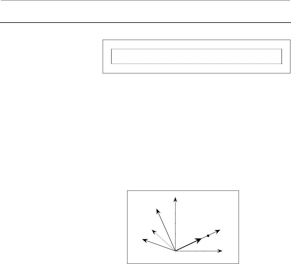
(2) The G68 block specifies data for conversion.
1 Origin of coordinate-conversion by x, y, and z (using
absolute values)
2 Nozzle axis tilt angle at the origin by a and b (normal line
to the workpiece)
3 The vector of the axis corresponding to the positive
direction of the X-axis of the program to be converted, by i,
j, and k (with the incremental value from the origin of the
coordinate-conversion)
Z'
Z
X'
X
Y
Y'
i, j, k
P
Ori
g
in
(
x,
y
, z
)
(3) The coordinate-conversion is executed based on the coordinate
system described below.
The coordinate system is determined by first defining the plane,
where the axis direction given by a and b is regarded as the
normal direction of the workpiece based on the origin having the
X-, Y-, and Z-axis coordinate values. Next, the workpiece plane
is rotated at the normal axis regarded as the rotational axis, and
then the +X axis in the program to be converted is directed in the
direction given by i, j, and k.
(4) The format can be taught easily by the teaching box.
The values of x, y, z, a, and b are defined by reading the current
position after positioning of the nozzle to the origin is executed
by teaching, and adjusting the attitude of the nozzle in the
normal direction of the workpiece. Then the nozzle is moved to
the point p to define the direction of the +X axis and the current
position of x1, y1, and z1 is read. Finally, the values of i, j, and
k are defined by calculating the formulas i=x1-x, j=y1-y, and
k=z1-z.
Contents Summary of Series 16i/160i - LA Descriptions
- Page 1DESCRIPTIONS B-63192EN/03�
- Page 2Ȧ No part of this manual may be reproduced in any form. Ȧ All specifications and designs are subject to change without notice. The export of this product is subject to the authorization of the government of the country from where the product is exported. In this manual we have tried as much as possi
- Page 3B-63192EN/03 TABLE OF CONTENTS TABLE OF CONTENTS 1 GENERAL................................ GENERAL ................................................................ ................................................................................................ .......................................
- Page 4TABLE OF CONTENTS B-63192EN/03 8.2.1 Data Area ................................................................................................................................. 36 8.2.2 Displaying the Data...............................................................................................
- Page 5B-63192EN/03 TABLE OF CONTENTSGENERAL 10.1.2 Attitude Control B (Offset Type Nozzle) ................................................................................ 63 10.1.3 Interaction Control ........................................................................................................
- Page 6
- Page 7B-63192EN/03 1.GENERAL 1 GENERAL The FANUC Series 16i/160i-LA is a CNC dedicated for use in a laser machine tool and developed based on the FANUC Series 16i/160i- MODEL A. When combined with a FANUC laser, it can be configured into a laser machine tool. This manual supplements "FANUC Series 16i/18i/
- Page 82.SPECIFICATIONS B-63192EN/03 2 SPECIFICATIONS For functions other than the laser functions, refer to "FANUC Series 16i/18i/21i/20i/160i/180i/210i-MODEL A Descriptions" (B- 63002EN). Some functions described in manual B-63002EN may not be supported by the 16i-LA/160i-LA or may differ from those of t
- Page 9B-63192EN/03 2.SPECIFICATIONS C series Item Specifications YP series Y series Overtravel Stored stroke check 1 Stored stroke limit external setting Stored stroke check 2 Stored stroke check 3 Stroke limit check before travel Mirror image Each axis Follow-up Servo-off/mechanical handle Backlash compe
- Page 102.SPECIFICATIONS B-63192EN/03 C series Item Specifications YP series Y series Exact stop G09 Linear interpolation Circular interpolation Supported for multiple quadrants Exponential interpolation Dwell Polar coordinate interpolation Cylindrical interpolation (Circular interpolation) + (Linear interp
- Page 11B-63192EN/03 2.SPECIFICATIONS C series Item Specifications YP series Y series Control in/out 1 block Optional block skip 9 blocks Maximum value ± with 8 digits O with 4 digits Program number O with 8 digits *1 Sequence number N with 5 digits Combined programming in a single block Absolute/incrementa
- Page 122.SPECIFICATIONS B-63192EN/03 Tool functions/Tool compensation functions C series Item Specifications YP series Y series Tool function T with 8 digits ± with 6 digits, 32 items ± with 6 digits, 64 items ± with 6 digits, 99 items Tool offset pairs ± with 6 digits, 200 items ± with 6 digits, 400 items
- Page 13B-63192EN/03 2.SPECIFICATIONS C series Item Specifications YP series Y series On-line custom screen *1 Reading information for mounted printed Remote diagnosis circuit board, CNC data such as parameters, * * alarm status, etc. Run time and parts number display Actual cutting speed display Floppy cas
- Page 142.SPECIFICATIONS B-63192EN/03 C series Item Specifications YP series Y series Memory card input/output *1 Screen hard copy *1 Power mate CNC manager *1 Laser control function C series Item Specifications YP series Y series Output power command 5 to 2000 Hz (C series, Y series) Pulse frequency comman
- Page 15B-63192EN/03 2.SPECIFICATIONS C series Item Specifications YP series Y series Three-dimensional conversion function Teaching function Spline interpolation function Others C series Item Specifications YP series Y series NC ready, servo ready, automatic operation, Status output signal reset, alarm, et
- Page 163.FUNCTIONS DIFFERENT FROM THOSE OF THE M SERIES CNC B-63192EN/03 3 FUNCTIONS DIFFERENT FROM THOSE OF THE M SERIES CNC Some functions described in "FANUC Series 16i/18i/21i/20i/160i/180i/210i-MODEL A Descriptions" (B- 63002EN) are supported by the 16i/160i-LA, but may be different in specification f
- Page 17B-63192EN/03 3.FUNCTIONS DIFFERENT FROM THOSE OF THE M SERIES CNC 3.1 EMERGENCY STOP If an emergency stop occurs when the oscillator is operating, the oscillator shutter is closed, the laser beam is turned off, the high- frequency power supply is turned off to stop discharge, and the assist gas sele
- Page 183.FUNCTIONS DIFFERENT FROM THOSE OF THE M SERIES CNC B-63192EN/03 3.5 SINGLE BLOCK When a block in which machining is carried out with the laser beam turned on ends, feeding stops, the laser beam is turned off, the shutter is closed, and the assist gas supply stops. Pressing the cycle start button s
- Page 19B-63192EN/03 4.LASER FUNCTIONS 4 LASER FUNCTIONS - 13 -�
- Page 204.LASER FUNCTIONS B-63192EN/03 4.1 LASER INTERFACE Because the 16i-LA can be connected to a laser oscillator via a dedicated interface, it can be used to configure a high-performance laser machine easily. (1) Connection via a serial interface The I/O link interface can be used to connect the 16i-LA
- Page 21B-63192EN/03 4.LASER FUNCTIONS 4.2 CONNECTABLE OSCILLATORS The following oscillators can be connected to the 16i-LA. 1 CO2 laser oscillator : FANUC LASER C series 2 Continuous-output YAG laser oscillator : FANUC LASER Y series 2 Pulse-output YAG laser oscillator : FANUC LASER YP series - 15 -�
- Page 225.LASER SEQUENCE CONTROL B-63192EN/03 5 LASER SEQUENCE CONTROL The 16i-LA supports laser sequence control for automatically starting and stopping the FANUC laser oscillator. Input/output signals provided between the CNC and PMC make it possible to program the start/stop operation of the laser oscill
- Page 23B-63192EN/03 5.LASER SEQUENCE CONTROL 5.1 SEQUENCE CONTROL OF THE C AND Y SERIES LASER OSCILLATORS The sequence control of the CO2 laser oscillator (C series) and the continuous-output YAG laser oscillator (Y series) is shown below. Oscillator not supplied with power Power on Power off Initial state
- Page 245.LASER SEQUENCE CONTROL B-63192EN/03 5.2 SEQUENCE CONTROL OF THE YP SERIES LASER OSCILLATORS The sequence control of the pulse-output YAG laser oscillator (YP series) is shown below. Oscillator not supplied with power Power on Power off Initial state Purge completed Stop oscillator Start oscillator
- Page 25B-63192EN/03 6.ASSIST GAS CONTROL 6 ASSIST GAS CONTROL - 19 -�
- Page 266.ASSIST GAS CONTROL B-63192EN/03 6.1 ASSIST GAS CONTROL Assist gas control is performed using a direct gas pressure control command or a flow pattern command. Direct gas pressure command The type and pressure of an assist gas to be used and the settling time of the assist gas pressure can be contro
- Page 27B-63192EN/03 6.ASSIST GAS CONTROL Control using the cutting condition setting function The type and pressure of an assist gas to be used and the settling time of the assist gas pressure can be controlled using the registered cutting condition data. G32 with L≠0 opens the shutter, and sends out the a
- Page 286.ASSIST GAS CONTROL B-63192EN/03 Flow pattern command The following pattern of data such as pre-stage pressure and time, cutting pressure, and post-stage pressure and time is previously registered as a flow pattern. It can be specified using the Q address. Cutting pressure Post-stage pressure Pre-s
- Page 29B-63192EN/03 6.ASSIST GAS CONTROL 6.2 ASSIST GAS PRESSURE ANALOG OUTPUT Specifying assist gas control causes the analog voltage signal to be generated according to the specified assist gas pressure. Operating the control valve according to this signal received at the outside enables automatic adjust
- Page 306.ASSIST GAS CONTROL B-63192EN/03 6.3 ASSIST GAS PRESSURE OVERRIDE The assist gas analog output can be overridden with a percentage from 0 to 200% in 1% steps. - 24 -�
- Page 31B-63192EN/03 7.SHUTTER OPEN/CLOSE CONTROL 7 SHUTTER OPEN/CLOSE CONTROL The oscillator output section has a safety provision. It is a shutter mechanism that can mechanically shut off the laser beam output as required. To output the laser beam, it is necessary to open the shutter previously. There are
- Page 328.LASER OUTPUT CONTROL B-63192EN/03 8 LASER OUTPUT CONTROL - 26 -�
- Page 33B-63192EN/03 8.LASER OUTPUT CONTROL 8.1 C AND Y SERIES LASER CONTROL The 16i-LA supports laser output control functions for the CO2 laser (C series) and continuous-output YAG laser (Y series). When the shutter is open, and the piercing command (G24) or a cutting feed command (G01, G02, G03, or G12)
- Page 348.LASER OUTPUT CONTROL B-63192EN/03 8.1.1 Power Value Command and Power Override The laser power is specified with a value that follows the S address in a laser output command. G01 X_Y_F_Sxxxx ; S : Specifies the power value. (*1) Valid data range : 0 to 7000 W Minimum increment : 1W (*1) The maximu
- Page 35B-63192EN/03 8.LASER OUTPUT CONTROL 8.1.2 Pulse Frequency Command and Frequency Override The frequency of the output pulse is specified by a value that follows the P address in the laser output command. G01 X_Y_F_S_Pxxxx ; P : Specifies the pulse frequency. Valid data range : 5 to 2000 Minimum incre
- Page 368.LASER OUTPUT CONTROL B-63192EN/03 8.1.3 Pulse Duty Cycle Command and Duty Cycle Override The duty cycle of the output pulse is specified by a value that follows the Q address in the laser output command. G01 X_Y_F_S_P_Qxxx ; Q : Specifies the pulse duty cycle. Valid data range : 0 to 100 Minimum i
- Page 37B-63192EN/03 8.LASER OUTPUT CONTROL 8.1.4 Piercing Commands The piercing function outputs the beam for a specified time, without moving the machine. This function is used to pierce a workpiece with the beam before starting to cut the workpiece. The piercing commands support high-speed piercing, whic
- Page 388.LASER OUTPUT CONTROL B-63192EN/03 (2) Indirect command If the optional cutting condition setting function is added, specify the piercing data number using address E to execute high-speed piercing. In this case, set a positive number in the "number of steps" item corresponding to the specified pier
- Page 39B-63192EN/03 8.LASER OUTPUT CONTROL 8.1.5 External Alteration of the Piercing Time The piercing time specified in G24 can be changed using an external signal. (1) Extending the piercing time If the "extension" signal is turned on during piercing, piercing continues as long as the signal remains on.
- Page 408.LASER OUTPUT CONTROL B-63192EN/03 8.1.6 Power Control The power control function controls the laser output by changing the actual feedrate. This function is valid when G63P1 is specified (where the power control for the laser settings is set to 1) and invalid when G63P0 is specified. To enable or
- Page 41B-63192EN/03 8.LASER OUTPUT CONTROL 8.1.8 Laser Machining Program Example S a1 E a5 b1 a2 a3 a4 b2 b3 G00X_ Y_ ; : Positioning at a1 from S G00Z_ ; : Positioning at a2 G13Pxxxx ; : Start tracing control. Approach a3. When approach is completed, the next block is executed. G32Px Txxx Rxxx ; : Open th
- Page 428.LASER OUTPUT CONTROL B-63192EN/03 8.2 CUTTING CONDITION SETTING FUNCTION This function saves laser machining data (otherwise specified using the S, P, and Q addresses separately) all together in memory and enables machining according to the saved data read out by specifying the corresponding data
- Page 43B-63192EN/03 8.LASER OUTPUT CONTROL (2) Cutting data group The cutting data group consists of ten sets of the data listed below. Its data numbers are 1 to 10 and specified with the E code. [Item] [Valid data range] [Minimum increment] Feedrate :0 to 99999 :mm/min Peak value for contouring :0 to 9999
- Page 448.LASER OUTPUT CONTROL B-63192EN/03 (5) Parameter switching data group The parameter switching data group consists of six sets of the following items. A data number is specified using an E code from 501 to 506. For details of the settings, refer to the "AC Servo Parameter Manual." [Parameter No.] X-
- Page 45B-63192EN/03 8.LASER OUTPUT CONTROL 8.2.3 Updating the Data (1) Correction function based on data screen operation Select and display a target screen, and press the [OPRT] soft key. Correction will be enabled. Place the cursor on the target item, and take the necessary action. When data at the curre
- Page 468.LASER OUTPUT CONTROL B-63192EN/03 8.2.4 Executing the Data (1) Piercing command When G24 is executed, a data group specified with the E code is read from the data area to carry out piercing. The E code can be specified independently. G24 Exxx ; Exxx : Piercing data number (101 to 103) (2) Reading
- Page 47B-63192EN/03 8.LASER OUTPUT CONTROL 8.2.5 Program Example The following example is a program using a cutting condition setting function. G92 X_Y_Z_ ; : Select a coordinate system. E01 ; : Specify a cutting data set number in the data area. E101 ; : Specify a piercing data set number in the data area
- Page 488.LASER OUTPUT CONTROL B-63192EN/03 8.2.6 Sending the Data The data area is limited in capacity. To store more data, it is necessary to expand the data area using a macro variable or battery-powered expansion memory, and send the necessary data from the expansion area to the data area as required. T
- Page 49B-63192EN/03 8.LASER OUTPUT CONTROL 8.3 EDGE MACHINING FUNCTION The edge machining function detects edges, controls deceleration-to- stop, performs piercing, and controls the feedrate and power during a shift from piercing to cutting. It is intended to produce sharp edges. Using this function requir
- Page 508.LASER OUTPUT CONTROL B-63192EN/03 8.3.2 Feedrate and Power Control Machining at a shift from block A to block B is carried out as shown below. Feedrate /power Fa Fb Se, Pe, Qe Sa, Pa, Qa Fr Sb, Pb, Qb Sb, Pr, Qr Time Block A Te Lr Block B Fa : Feedrate in block A Sa : Output peak value in block A
- Page 51B-63192EN/03 8.LASER OUTPUT CONTROL 8.3.3 Data Setting See the description of the cutting condition setting function for the edge machining data item. 8.3.4 Command The edge machining function is enabled by specifying an edge data number at "edge selection" in the machining data specified with the E
- Page 528.LASER OUTPUT CONTROL B-63192EN/03 8.4 START-UP FUNCTION When a shift occurs from piercing to cutting, cutting may not be stable if it is started with the cutting data. The start-up function controls the feedrate and power at a shift from piercing to cutting in the same manner as with the end of ed
- Page 53B-63192EN/03 8.LASER OUTPUT CONTROL 8.4.2 Setting the Data The following edge machining data specified using the cutting condition setting function becomes effective. [Item] [Valid data range] [Minimum increment] Return distance :0 to 99.999 :mm Return speed :0 to 9999 :mm/min Return frequency :5 to
- Page 548.LASER OUTPUT CONTROL B-63192EN/03 8.5 GUIDE LIGHT ON SIGNAL If the laser oscillator is equipped with the guide light option (semiconductor laser or He-Ne laser unit), the laser beam from the guide light laser unit can be switched on and off using an external signal. If the oscillator shutter is cl
- Page 55B-63192EN/03 8.LASER OUTPUT CONTROL 8.6 STATUS OUTPUT SIGNAL 8.6.1 Piercing Signal For the C and Y series oscillators, if G24 is executed to specify piercing, the piercing signal is output when piercing is being carried out. 8.6.2 Laser Processing Signal For the C and Y series oscillators, the laser
- Page 568.LASER OUTPUT CONTROL B-63192EN/03 8.6.4 Laser Alarm Signal A laser alarm is raised if an error related to the laser oscillator is detected. (1) C and Y series oscillators • Low water level • Chiller unit failure • Abnormal laser gas pressure • Abnormal exhaust time • Root blower failure • Abnormal
- Page 57B-63192EN/03 8.LASER OUTPUT CONTROL 8.6.5 Status Output Signals (1) Purge completion signal This signal is issued, when the unit is switched on, and the CNC starts operating. When this signal is issued, the RUN signal becomes acceptable. When the RUN signal is turned off, purge processing occurs to
- Page 588.LASER OUTPUT CONTROL B-63192EN/03 8.7 STEP FUNCTION The step function controls the laser power in steps for a set distance, starting from the weld start point and for another set distance ending at the weld end point when welding is performed with laser beam machining, to achieve good welding resu
- Page 59B-63192EN/03 8.LASER OUTPUT CONTROL • Valid data ranges The valid data ranges are as follows: Ramp UP/DOWN step distance : 0 to 65.000 mm Step power : 0 to 7000 W Ramp UP/DOWN operation is performed by measuring the distance of the straight line from the machining start point to the machining end po
- Page 608.LASER OUTPUT CONTROL B-63192EN/03 • This function is not effective when the single block, dry run, or machine lock function is used. • This function is valid only for X-Y facing. It cannot be used with functions for cylindrical machining, normal direction control, three-dimensional machining, etc.
- Page 61B-63192EN/03 9.TRACING CONTROL 9 TRACING CONTROL - 55 -�
- Page 629.TRACING CONTROL B-63192EN/03 9.1 TRACING FUNCTION The machine is equipped with a detector to measure the distance to the surface of the workpiece. An analog signal generated in this detector is sent to the CNC through a specified interface. This signal enables gap control in which the Z-axis is co
- Page 63B-63192EN/03 9.TRACING CONTROL 9.1.3 Tracing Speed On receiving an analog signal from the detector, the CNC subtracts the reference deviation E0 from it and multiplies the difference by loop gain K to calculate the speed command for the Z-axis. The loop gain can be specified using a parameter. Vz =
- Page 649.TRACING CONTROL B-63192EN/03 9.1.6 Tracing Adjustment Function The tracing adjustment function enables zero-point and detection gain factor adjustments necessary to normalize the input signal to the specified deviation. This is done using soft keys displayed on the CRT screen. 9.1.7 Tracing Alarms
- Page 65B-63192EN/03 9.TRACING CONTROL 9.2 TRACING INTERLOCK FUNCTION If the machine receives a tracing interlock signal from the PMC during tracing operation specified by G13; , it suspends the operation of the tracing axis as long as the signal is on. When the tracing interlock signal is turned off, the m
- Page 6610.FUNCTION FOR THREE-DIMENSIONAL PROCESSING SYSTEM B-63192EN/03 10 FUNCTION FOR THREE-DIMENSIONAL PROCESSING SYSTEM - 60 -�
- Page 67B-63192EN/03 10.FUNCTION FOR THREE-DIMENSIONAL PROCESSING SYSTEM 10.1 ATTITUDE CONTROL If the fifth and sixth axes are specified as a controlled axis, and attitude control is specified, the nozzle attitude can be controlled around the two axes, thus enabling configuring of a three-dimensional machin
- Page 6810.FUNCTION FOR THREE-DIMENSIONAL PROCESSING SYSTEM B-63192EN/03 10.1.1 Attitude Control A (Zero Offset Type Nozzle) The nozzle tip position fixed type (zero offset type) mechanism is configured with the α axis (4th axis) to rotate around Z axis, and the rotational axis β axis (5th axis) recorded in
- Page 69B-63192EN/03 10.FUNCTION FOR THREE-DIMENSIONAL PROCESSING SYSTEM 10.1.2 Attitude Control B (Offset Type Nozzle) The offset type mechanism is configured with the α axis (4th axis) to rotate around Z axis, and the rotational axis β axis (5th axis) recorded in this α axis. It possesses the structure of
- Page 7010.FUNCTION FOR THREE-DIMENSIONAL PROCESSING SYSTEM B-63192EN/03 (1) Mode selection In automatic operation, the nozzle tip fixed mode automatically occurs. In manual operation, an external signal can be used to switch between nozzle tip fixed mode and independent axis mode. (2) Independent axis mode
- Page 71B-63192EN/03 10.FUNCTION FOR THREE-DIMENSIONAL PROCESSING SYSTEM 10.1.3 Interaction Control In nozzle attitude control, as shown in the diagram of the axis configuration of the nozzle head, the β axis motor is arranged around the Z axis. In the case of a structure which transmits by gear, if the α a
- Page 7210.FUNCTION FOR THREE-DIMENSIONAL PROCESSING SYSTEM B-63192EN/03 10.2 TEACHING BOX INTERFACE The CNC can be connected to a teaching box interface in the machine through a serial interface. The CNC can send teaching data requested by the teaching box (TB). It can also receive commands generated by te
- Page 73B-63192EN/03 10.FUNCTION FOR THREE-DIMENSIONAL PROCESSING SYSTEM K : Writes the specified block (insertion) L : Deletes the specified block M : Sequence number search N : Command of the MDI operation O : Nozzle tip machine position data P : Request three-dimensional conversion data. Q : Register thr
- Page 7410.FUNCTION FOR THREE-DIMENSIONAL PROCESSING SYSTEM B-63192EN/03 10.3 THREE-DIMENSIONAL CONTROL FUNCTION 10.3.1 W Axis Tracing Control The W axis is arranged such that linear operation of the nozzle tip section can be performed, and the gap sensor is connected at the prescribed interface. If this fu
- Page 75B-63192EN/03 10.FUNCTION FOR THREE-DIMENSIONAL PROCESSING SYSTEM 10.3.2 Spatial Circular Interpolation Command method G12 Xx1 Yy1 Zz1 Aa1 Bb1 Ss Pp Qq ; G12 Xx2 Yy2 Zz2 Aa2 Bb2 ; The first block represents the intermediate point on an arc, and the second block represents the end point of the arc. If
- Page 7610.FUNCTION FOR THREE-DIMENSIONAL PROCESSING SYSTEM B-63192EN/03 10.3.3 Three-dimensional Coordinate Conversion Command method G68 Xx Yy Zz Aa Bb Ii Jj Kk ; Program to be converted G69 ; The program put in between the commands G68 and G69 is coordinate- converted. (1) The program to be converted is
- Page 77B-63192EN/03 10.FUNCTION FOR THREE-DIMENSIONAL PROCESSING SYSTEM 10.3.4 Spatial Corner-R Insertion Command method G33 Rr ; Target program G34 ; (1) The arc having the specified radius is automatically inserted to each corner obtained by the spatial dot-strings put in between commands G33 and G34. (2
- Page 7810.FUNCTION FOR THREE-DIMENSIONAL PROCESSING SYSTEM B-63192EN/03 10.3.5 Three-dimensional Conversion Function A machining program is subjected to three-dimensional conversion by specifying a target point in reference to an arbitrary point in the coordinate system of the machining program. This funct
- Page 79B-63192EN/03 10.FUNCTION FOR THREE-DIMENSIONAL PROCESSING SYSTEM (a) Mirror image conversion G98 P0 X_Y_Z_ ; Reference point G98 Q0 X_Y_Z_ ; Target point (b) Three-dimensional movement conversion G98 P1 X_Y_Z_ ; Reference point G98 P2 X_Y_Z_ ; Reference point G98 P3 X_Y_Z_ ; Reference point G98 Q1 X
- Page 8010.FUNCTION FOR THREE-DIMENSIONAL PROCESSING SYSTEM B-63192EN/03 10.3.6 Proximity Point Search In the memory operation mode, if the proximity point search (DI) is turned on and the cycle start is carried out, the block in the nearest position to the current position of the nozzle is searched as desc
- Page 81B-63192EN/03 10.FUNCTION FOR THREE-DIMENSIONAL PROCESSING SYSTEM 10.3.7 Manual Operation Using a Hand Coordinate System A hand coordinate system can be generated in which the origin is at the tip of the nozzle, +Zh coincides with the line normal to the nozzle, +Xh coincides with the arm direction, a
- Page 8211.CONTROL FUNCTIONS B-63192EN/03 11 CONTROL FUNCTIONS - 76 -�
- Page 83B-63192EN/03 11.CONTROL FUNCTIONS 11.1 OPTICAL PATH LENGTH COMPENSATION If there is a movable reflector, the propagation distance between the oscillator and condensing lens varies as the reflector moves. Generally, stable machining characteristics are obtained within a limited propagation distance r
- Page 8411.CONTROL FUNCTIONS B-63192EN/03 (1) Detectors on the controlled axes can be incremental and/or absolute pulse coders (APC). The two types can be intermixed. (2) Any axis from the fourth axis to the eight axis can be assigned as the U-axis. (3) A U-axis move command is generated based on the moveme
- Page 85B-63192EN/03 11.CONTROL FUNCTIONS 11.2 MACHINING RESTART FUNCTION Burning may occur during laser machining, preventing machining from continuing. In such a case, machining may be resumed by putting the machine back in the state in which it was before burning. This is done by a machining restart func
- Page 8611.CONTROL FUNCTIONS B-63192EN/03 <3> When retracting is completed, the machine retraces the specified distance, then stops. After confirming the retrace completed signal and turning off the retrace signal, triggering automatic operation causes the nozzle to approach the surface of the workpiece. <4
- Page 87B-63192EN/03 12.LASER FUNCTIONS OF THE YP SERIES OSCILLATORS 12 LASER FUNCTIONS OF THE YP SERIES OSCILLATORS This chapter contains the information necessary to control a FANUC YP Series laser oscillator in the FANUC Series 16i-LA, and explains the specifications different from those of the FANUC LAS
- Page 8812.LASER FUNCTIONS OF THE YP SERIES OSCILLATORS B-63192EN/03 12.1 OSCILLATOR CONTROLS The following oscillator controls are performed: • Oscillator start/stop sequence control • Output compensation function that automatically compensates the laser output • Detection of return light • Output waveform
- Page 89B-63192EN/03 12.LASER FUNCTIONS OF THE YP SERIES OSCILLATORS 12.2 AUTOMATION FUNCTIONS NOT AVAILABLE TO THE YP SERIES OSCILLATORS The following functions are not supported by the YP series oscillators. They are for the C and Y series oscillators only. • Machining condition setting function • Edge ma
- Page 9012.LASER FUNCTIONS OF THE YP SERIES OSCILLATORS B-63192EN/03 12.3 SETTING AND TRANSFERRING WAVEFORM DATA Before machining can start, a YP Series laser oscillator requires that output waveform data be set in the memory area of the CNC and transferred to the oscillator. This section explains how to se
- Page 91B-63192EN/03 12.LASER FUNCTIONS OF THE YP SERIES OSCILLATORS WAVE DATA(2/1) STEP NO. WAVE NO.1 NO.2 NO.3 NO.4 NO.5 NO.6 NO.7 NO.8 1 **** **** **** **** **** **** **** **** 2 **** **** **** **** **** **** **** **** 3 **** **** **** **** **** **** **** **** 4 **** **** **** **** **** **** **** **** 5
- Page 9212.LASER FUNCTIONS OF THE YP SERIES OSCILLATORS B-63192EN/03 12.3.2 Command Format Setting Waveform data can be stored in the data area in the CNC, in the following command format: G26 P_ K_ I_ ; - Explanation of the command format Command Description P_ One of the numbers assigned to 16 sets of wav
- Page 93B-63192EN/03 12.LASER FUNCTIONS OF THE YP SERIES OSCILLATORS 12.4 REGISTERING EXECUTION PRIORITIES AND OUTPUT FORMATS The controller provides the registers for registering execution priorities so that the laser output can be controlled uninterruptedly. There are eight such registers, and a single re
- Page 9412.LASER FUNCTIONS OF THE YP SERIES OSCILLATORS B-63192EN/03 12.4.2 Command Format G25 L_ J_ (P_ K_ R_ S_) ; - Explanation of the command format Command Description L_ Specify the number of the register in which to register Register number an execution priority. Valid range: 1 to 8 J_ Specify an exe
- Page 95B-63192EN/03 12.LASER FUNCTIONS OF THE YP SERIES OSCILLATORS 12.5 LASER OUTPUT COMMANDS This section explains output commands. 12.5.1 Specifying an Active Register Number To perform machining, it is necessary to specify which of the eight execution priority registers to use: Specify the register bef
- Page 9612.LASER FUNCTIONS OF THE YP SERIES OSCILLATORS B-63192EN/03 12.5.3 Drilling Output Command Command format examples - For a single block G24 E_ ; - For an independent block E_ ; G24 ; A drilling output command is executed with G24. Data is read from the register specified with the E code in order, a
- Page 97APPENDI�
- Page 98
- Page 99B-63192EN/03 APPENDIX A.LASER SETTING SCREEN A LASER SETTING SCREEN (1) Laser power display The laser output display screen displays the following data. LASER POWER O0000 N00000 PC 1000 W PA 1000 W FR 2000 Hz DU 100 % E 0.000 MM >_ S 0 T0000 MDI **** *** *** 21:20:07 [ POWER ][ SET ][ ][ ][ ] - 93 -
- Page 100A.LASER SETTING SCREEN APPENDIX B-63192EN/03 (2) Laser setting The laser setting screen consists of three pages shown below. LASER SETTING O0000 N00000 CONTOURING POWER = 1000 W FREQUENCY= 2000 Hz DUTY = 100 % PIERCING POW4R = 800 W FREQUENCY= 1000 Hz DUTY = 50 % POWER SELECT = 0 (0:ALL,1:HLF) POWER
- Page 101B-63192EN/03 APPENDIX A.LASER SETTING SCREEN (3) Trace setting This screen displays the following tracing data. TRACE SETTING O0000 N00000 Z-DEFLECTIONPOSITION = 1.000 (RELATIVE) ZERO ADJUST X 7.213 E 0.143 Y 9.596 GAIN COEFFICIENT Z -14.559 START POINT Z -14.059 E 0.048 END POINT Z -14.559 DEFLECTI
- Page 102B.CUTTING CONDITION SETTING SCREENS APPENDIX B-63192EN/03 B CUTTING CONDITION SETTING SCREENS (1) Cutting data screen This screen displays the following cutting data. [CUTTING] ACTIVE DATA NO. [CUTTING=5 PIRCING=103] GAS GAS GAS START No. FEED PWR FREQ. DUTY PRES. KIND TIME DEF EDGE UP 1 ***** ****
- Page 103B-63192EN/03 APPENDIX B.CUTTING CONDITION SETTING SCREENS (3) Edge machining data screen This screen displays the following edge machining data. [EDGE] ACTIVE DATA NO.[CUTTING=5 PIRCING=103] PIRC GAS GAS STRTSTRT STRT STRT No. ANGL PWR. FREQ. DUTY TIME PRSS. KIND DIST FEED FREQ. DUTY 201 *** **** **
- Page 104C.YP SERIES STATUS DISPLAY SCREEN APPENDIX B-63192EN/03 C YP SERIES STATUS DISPLAY SCREEN It prepares for the following screen that it is indicated the output condition of oscillator. STATUS O 0001 N 00001 RG REGISTER NO. 5 FA SPEED 1000 MM/MIN SQ ORDER 1 PA AVE. PWR 500 W WN WAVE NO. 12 MP WAVE COE
- Page 105B-63192EN/03 INDEX INDEX Execution Priority Display Screen................... 87 A External Alteration of the Piercing Time........ 33 A-axis Length Compensation Function........... 65 F ASSIST GAS CONTROL............................ 19, 20 ASSIST GAS PRESSURE ANALOG OUTPUT FEED HOLD ...............
- Page 106INDEX B-63192EN/03 Manual Operation Using a Hand Coordinate Setting the Data................................................ 47 System ........................................................... 75 SHUTTER OPEN/CLOSE CONTROL ............ 25 SINGLE BLOCK...............................................
- Page 107Revision Record FANUC Series 16i/160i-LA DESCRIPTIONS (B-63192EN) • Addition of YP series Laser 03 Feb., 2002 • Correction of errors • Addition of step function 02 Nov., 2000 • Correction of errors 01 May, 1998 Edition Date Contents Edition Date Contents
- Page 108