Linear Motor Lis Descriptions Page 166
Descriptions
2.MECHANICAL DESIGN HANDLING, DESIGN, AND ASSEMBLY B-65382EN/02
- 144 -
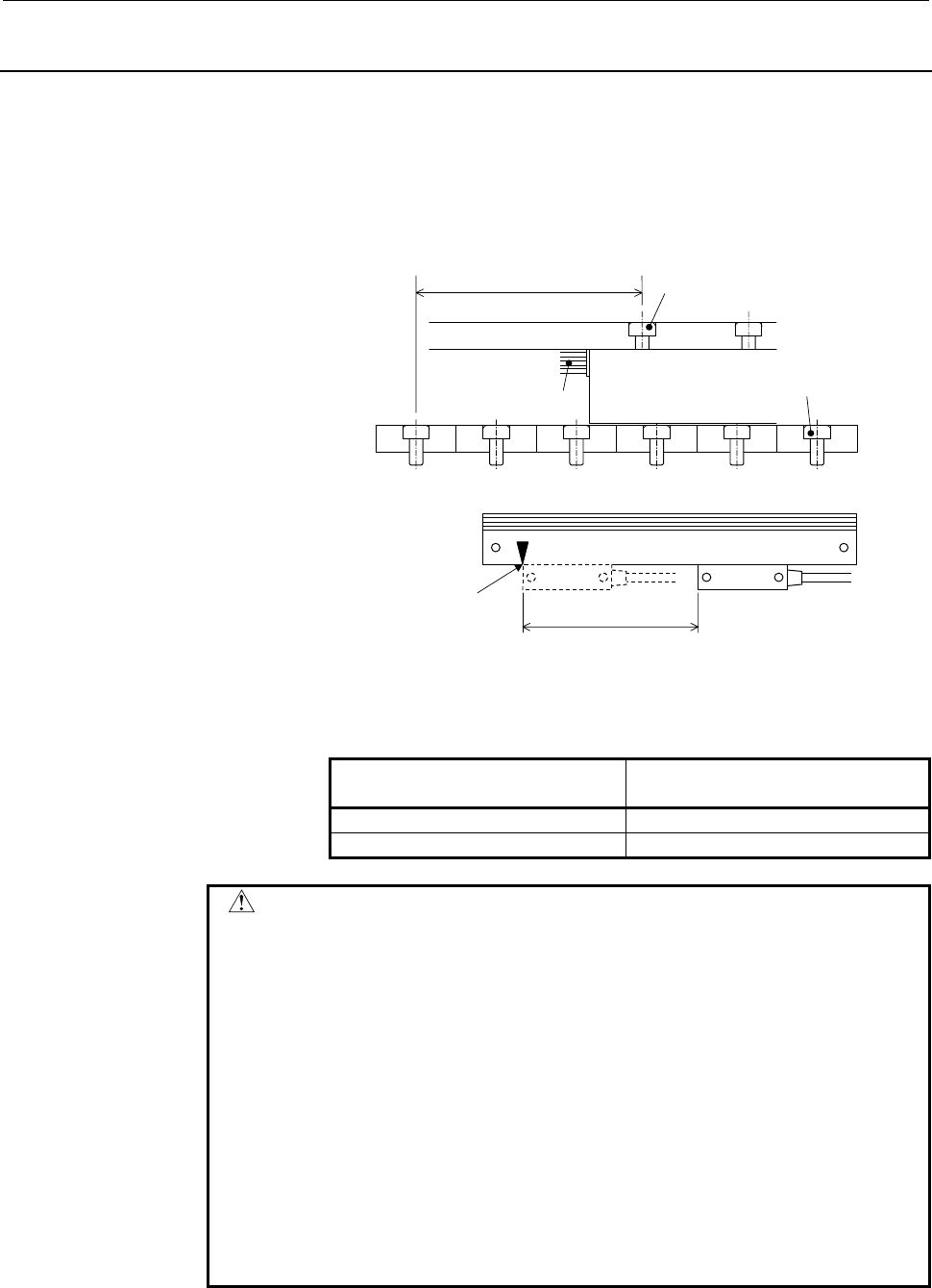
2.6.5 Distance Coded Linear Encoder Mounting Position
For LiS 300A1/4, LiS 600A1/4, and LiS 900A1/4
The mounting position of the HEIDENHAIN's distance coded linear
encoder must follow that of an absolute linear encoder. The following
positional relationships and expressions must be satisfied at the same
time.
N SN SN SN SN SN S
L
Power line
Coil slider
Slider mounting screw
nearest to the power line
Magnet plate
mounting screw
Distance coded linear encode
r
S
Position of the head end face when
the encoder detects the origin
Mount a linear motor and linear encoder at the following position in
the figure above:
S = 30 × N (mm) N: Natural number or 0
Magnet end face on the magnetic
pole sensor side
L (mm) M: Natural number
N pole L=30×M+17.5±0.5 (mm)
S pole L=30×M+2.5±0.5 (mm)
CAUTION
1 Before mounting a linear encoder, check that the positive
direction of the linear motor matches the positive direction of
the linear encoder. If a positive direction mismatch exists, the
motor can become uncontrollable in the worst case. For the
method of checking, see Subsection 2.4.2, "Linear Motor and
Linear Encoder Directions".
2 If a linear encoder is mounted at an incorrect position, the
power factor can drop, and a soft thermal (OVC) alarm can be
issued. In addition, the motor can become uncontrollable in the
worst case. Before turning on the power to the machine after
machine assembly, recheck the positional relationships.
3 The distance coded linear encoder is an incremental encoder.
The magnetic pole sensor and position detection circuit C must
be connected in addition to the connections in the above figure.
Contents Summary of Linear Motor Lis Descriptions
- Page 1FANUC LINEAR MOTOR L*S series DESCRIPTIONS B-65382EN/02
- Page 2FOR USER Before getting started • Read this manual thoroughly before using FANUC LINEAR MOTOR. It contains many important items. • Do not try operation not described in this manual without permission. Otherwise, your motor may get into trouble. If it is unavoidable to operate your motor in a way not
- Page 3B-65382EN/02 SAFETY PRECAUTIONS SAFETY PRECAUTIONS This "Safety Precautions" section describes the precautions which must be observed to ensure safety when using FANUC linear motors. Users of any linear motor model are requested to read this manual carefully before using the linear motor. The users
- Page 4SAFETY PRECAUTIONS B-65382EN/02 DEFINITION OF WARNING, CAUTION, AND NOTE This manual includes safety precautions for protecting the user and preventing damage to the machine. Precautions are classified into Warning and Caution according to their bearing on safety. Also, supplementary information is
- Page 5B-65382EN/02 SAFETY PRECAUTIONS WARNING WARNING - Be safely dressed when handling a motor. Wear safety shoes or gloves when handling a motor as you may get hurt on any edge or protrusion on it or electric shocks. - Any person having a medical apparatus must keep at least 30 cm away from any magnet p
- Page 6SAFETY PRECAUTIONS B-65382EN/02 WARNING - When moving the motor, use a crane or another equipment. A motor is a heavy object. Use a crane or another equipment as required (for the weight of the motor, see this manual). When moving the motor, lift it using a fabric rope passed round the motor in bala
- Page 7B-65382EN/02 SAFETY PRECAUTIONS WARNING - While the motor is running, do not get near or touch the motor driving section. While the motor is running, getting near or touching the motor driving section may entangle cloths or fingers with the motor or cause a collision with a movable part. Before runn
- Page 8SAFETY PRECAUTIONS B-65382EN/02 CAUTION CAUTION - Keep electronic devices and magnetic media away from any magnet plate. Bring an electronic device such as a personal computer, camera, or cellular phone or magnetic media such as a magnetic card or disk near a magnet plate may cause a failure or dama
- Page 9B-65382EN/02 SAFETY PRECAUTIONS NOTE NOTE - Do not step or sit on a motor. If you step or sit on a motor, it may get deformed or broken. Do not put a motor on another unless they are in packages. - When storing a motor, put it in a dry (non-condensing) place at room temperature (0 to 40 °C). If a mo
- Page 10SAFETY PRECAUTIONS B-65382EN/02 NOTE - Do not apply a commercial power source voltage directly to a motor. Applying a commercial power source voltage directly to a motor may result in its windings being burned. Be sure to use a specified amplifier for supplying voltage to the motor. - Before using a
- Page 11B-65382EN/02 PREFACE PREFACE This manual covers information on the following models: FANUC LINEAR MOTOR LiS series Model LiS 300A1/4 Model LiS 600A1/4 Model LiS 900A1/4 Model LiS 1500B1/4 Models LiS 3000B2/2 and LiS 3000B2/4 Models LiS 4500B2/2 and L4500B2/2HV Models LiS 6000B2/2, LiS 6000B2/4, and
- Page 12PREFACE B-65382EN/02 ORGANIZATION OF THIS MANUAL This manual is mainly divided into the following five chapters: I. SPECIFICATIONS Contains information about the specifications of linear motors such as force versus speed diagrams, external dimensions, and cooling conditions. II. CONFIGURATIONS AND S
- Page 13B-65382EN/02 PREFACE ACCEPTANCE AND STORAGE WARNING Mishandling a magnet plate may be highly dangerous, resulting in a fatal accident. Read and thoroughly understand the cautions on the next page and Part III, "HANDLING, DESIGN, AND ASSEMBLY," before handling the magnet plate and strictly observe th
- Page 14PREFACE B-65382EN/02 HANDLING A MAGNET PLATE (CAUTIONS) WARNING 1 Mishandling a magnet plate may be highly dangerous, resulting in a fatal accident. Read and thoroughly understand these cautions and Part III, "HANDLING, DESIGN, AND ASSEMBLY," before handling the magnet plate and strictly observe the
- Page 15B-65382EN/02 PREFACE The following items may be affected by magnetic fields, resulting in damage or malfunction. When handling the magnet plate, do not carry any item listed below (or another item which is not listed) with you and keep the items away from the magnet fields unless it is necessary. FA
- Page 16
- Page 17B-65382EN/02 TABLE OF CONTENTS TABLE OF CONTENTS SAFETY PRECAUTIONS............................................................................s-1 DEFINITION OF WARNING, CAUTION, AND NOTE ............................................. s-2 WARNING ......................................................
- Page 18TABLE OF CONTENTS B-65382EN/02 2.6 APPLICABLE AMPLIFIERS......................................................................... 73 II. CONFIGURATIONS AND SELECTION 1 SYSTEM CONFIGURATION................................................................. 79 1.1 LINEAR ENCODER SELECTION...............
- Page 19B-65382EN/02 TABLE OF CONTENTS 1.2 MAGNET PLATE ....................................................................................... 119 1.3 SENSOR ................................................................................................... 121 2 MECHANICAL DESIGN .........................
- Page 20TABLE OF CONTENTS B-65382EN/02 2.20 INDICATION OF WARNING...................................................................... 164 3 ASSEMBLY......................................................................................... 165 3.1 LINEAR MOTOR MOUNTING PROCEDURES............................
- Page 21B-65382EN/02 TABLE OF CONTENTS 3.2 CONFIRMATION ON THE CNC SCREEN ................................................ 198 4 PARAMETER SETTING...................................................................... 199 5 TROUBLES AND CAUSES ................................................................
- Page 22
- Page 23I. SPECIFICATION
- Page 24
- Page 25B-65382EN/02 SPECIFICATIONS 1.OVERVIEW 1 OVERVIEW Parts supplied by FANUC The following shows a typical system configuration of the FANUC Linear Motor LiS series. Thermostat line Servo amplifier Magnet plate Coil slider Magnetic pole sensor FSSB Power line Position detection circuit Linear encoder F
- Page 261.OVERVIEW SPECIFICATIONS B-65382EN/02 FANUC does not supply parts listed below. Use parts manufactured by third parties as required. • Linear encoder • Movable cable and others • Linear guide • Cable carrier • Axis cover • Scraper • Cooling devices (cooler, fan, and others) • Shock absorber • Exter
- Page 27B-65382EN/02 SPECIFICATIONS 2.SPECIFICATIONS 2 SPECIFICATIONS -5-
- Page 282.SPECIFICATIONS SPECIFICATIONS B-65382EN/02 2.1 TERMS USED IN THE SPECIFICATION LIST AND SPEED DIAGRAMS - Cooling method There are the following methods for cooling a coil slider: No cooling, air cooling, and water cooling. - Maximum speed Maximum speed of the motor. You can run the motor at up to
- Page 29B-65382EN/02 SPECIFICATIONS 2.SPECIFICATIONS - Maximum current Effective current per phase when the motor outputs the maximum force. The peak value can be obtained by multiplying this value by 2. - Continuous output/maximum output Value obtained by converting the force (N) during motor operation to
- Page 302.SPECIFICATIONS SPECIFICATIONS B-65382EN/02 2.2 SPECIFICATION LIST *1 Model Item Symbol Unit LiS 300A1/4 LiS 600A1/4 LiS 900A1/4 No Air Water No Air Water No Air Water Cooling method (*2) - - cooling cooling cooling cooling cooling cooling cooling cooling cooling Maximum speed - m/s 4 4 4 Upper spe
- Page 31B-65382EN/02 SPECIFICATIONS 2.SPECIFICATIONS *1 Model Unit Symbol Item LiS 1500B1/4 LiS 3000B2/2 LiS 3000B2/4 No Air Water No Air Water No Air Water cooling cooling cooling cooling cooling cooling cooling cooling cooling - - Cooling method (*2) 4 2 (4) 4 m/s - Maximum speed Upper speed for the 2 1 (
- Page 322.SPECIFICATIONS SPECIFICATIONS B-65382EN/02 *1 Model Item Symbol Unit LiS 4500B2/2 LiS 6000B2/2 LiS 6000B2/4 No Air Water No Air Water No Air Water Cooling method (*2) - - cooling cooling cooling cooling cooling cooling cooling cooling cooling Maximum speed - m/s 2 (4) 2(4) 4 Upper speed for the ma
- Page 33B-65382EN/02 SPECIFICATIONS 2.SPECIFICATIONS *1 Model Unit Symbol Item LiS 7500B2/2 LiS 9000B2/2 LiS 9000B2/4 No Air Water No Air Water No Air Water cooling cooling cooling cooling cooling cooling cooling cooling cooling - - Cooling method (*2) 2(4) 2 (4) 4 m/s - Maximum speed Upper speed for the 1(
- Page 342.SPECIFICATIONS SPECIFICATIONS B-65382EN/02 *1 Model Item Symbol Unit LiS 3300C1/2 LiS 9000C2/2 LiS 11000C2/2 No Air Water No Air Water No Air Water Cooling method (*2) - - cooling cooling cooling cooling cooling cooling cooling cooling cooling 2(4) Maximum speed - m/s 2 (4) 2(4) Upper speed for th
- Page 35B-65382EN/02 SPECIFICATIONS 2.SPECIFICATIONS *1 Model Unit Symbol Item LiS 15000C2/2 LiS 15000C2/3 LiS 10000C3/2 No Air Water No Air Water No Air Water cooling cooling cooling cooling cooling cooling cooling cooling cooling - - Cooling method (*2) 2(4) 3 2(4) m/s - Maximum speed Upper speed for the
- Page 362.SPECIFICATIONS SPECIFICATIONS B-65382EN/02 *1 Model Item Symbol Unit LiS 17000C3/2 LiS 4500B2/2HV LiS 6000B2/2HV No Air Water No Air Water No Air Water Cooling method (*2) - - cooling cooling cooling cooling cooling cooling cooling cooling cooling Maximum speed - m/s 2 (4) (2) (2) Upper speed for
- Page 37B-65382EN/02 SPECIFICATIONS 2.SPECIFICATIONS *1 Model Unit Symbol Item LiS 7500B2/2HV LiS 9000C2/2HV LiS 11000C2/2HV No Air Water No Air Water No Air Water cooling cooling cooling cooling cooling cooling cooling cooling cooling - - Cooling method (*2) (2) (2) (2) m/s - Maximum speed Upper speed for
- Page 382.SPECIFICATIONS SPECIFICATIONS B-65382EN/02 *1 Model Item Symbol Unit LiS 15000C2/3HV LiS 10000C3/2HV LiS 17000C3/2HV No Air Water No Air Water No Air Water Cooling method (*2) - - cooling cooling cooling cooling cooling cooling cooling cooling cooling Maximum speed - m/s (3) (2) (2) Upper speed fo
- Page 39B-65382EN/02 SPECIFICATIONS 2.SPECIFICATIONS 2.3 FORCE-VERSUS-SPEED DIAGRAMS AND OUTPUT-VERSUS-SPEED DIAGRAMS LiS 300A1/4 (A06B-0441-B200#0000) 350 0.8 300 0.7 0.6 Maximum output 250 Maximum force Output (kW) 0.5 Force (N) 200 0.4 Water cooling 150 Water cooling 0.3 Air cooling 100 Air cooling 0.2 5
- Page 402.SPECIFICATIONS SPECIFICATIONS B-65382EN/02 LiS 1500B1/4 (A06B-0444-B210#0000) 1600 3.5 1400 Maximum force 3 Maximum output 1200 2.5 1000 Force (N) Output (kW) 2 Water cooling 800 Water cooling 1.5 Air cooling 600 Air cooling 400 1 200 0.5 No cooling No cooling 0 0 0 1 3 4 0 1 2 3 4 Speed (m/s) Spe
- Page 41B-65382EN/02 SPECIFICATIONS 2.SPECIFICATIONS LiS 4500B2/2HV (A06B-0446-B010#0000 driven with 400 V) LiS 4500B2/2 (A06B-0446-B110#0000) 5000 6 4500 5 4000 Maximum output Maximum force 3500 4 Output (kW) 3000 Water cooling Force (N) 2500 3 Water cooling Air cooling 2000 Air cooling 2 1500 1000 1 500 N
- Page 422.SPECIFICATIONS SPECIFICATIONS B-65382EN/02 LiS 6000B2/4 (A06B-0447-B210#0000) LiS 6000B2/2 (A06B-0447-B110#0000 driven with 400 V) 7000 6000 Maximum force Maximum output 5000 Water cooling Output (kW) Force (N) 4000 Water cooling 3000 Air cooling 2000 Air cooling 1000 No cooling No cooling 0 0 1 2
- Page 43B-65382EN/02 SPECIFICATIONS 2.SPECIFICATIONS LiS 9000B2/2 (A06B-0449-B110#0000) 10000 12 9000 10 8000 Maximum output Maximum force 7000 8 Output (kW) 6000 Water cooling Force (N) 5000 Water cooling 6 Air cooling 4000 Air cooling 4 3000 2000 2 1000 No cooling No cooling 0 0 0.0 0.5 1.0 1.5 2.0 0.0 0.
- Page 442.SPECIFICATIONS SPECIFICATIONS B-65382EN/02 LiS 3300C1/2 (A06B-0451-B110#0000 driven with 400 V) Maximum force Maximum output Output (kW) Force (N) Water cooling Water cooling Air cooling Air cooling No cooling No cooling Speed (m/s) Speed (m/s) LiS 9000C2/2HV (A06B-0454-B010#0000 driven with 400 V
- Page 45B-65382EN/02 SPECIFICATIONS 2.SPECIFICATIONS LiS 9000C2/2 (A06B-0454-B110#0000 driven with 400 V) 10000 25 9000 Maximum output 8000 20 Maximum force 7000 Output (kW) 6000 15 Force (N) Water cooling 5000 Water cooling Air cooling 4000 10 3000 Air cooling 2000 5 1000 No cooling No cooling 0 0 0 1 2 3
- Page 462.SPECIFICATIONS SPECIFICATIONS B-65382EN/02 LiS 11000C2/2 (A06B-0455-B110#0000 driven with 400 V) 12000 25 Maximum output 10000 20 Maximum force 8000 Output (kW) 15 Water cooling Force (N) 6000 Water cooling Air cooling 10 4000 Air cooling 2000 5 No cooling No cooling 0 0 0 1 2 3 4 0 1 2 3 4 Speed
- Page 47B-65382EN/02 SPECIFICATIONS 2.SPECIFICATIONS LiS 15000C2/2 (A06B-0456-B110#0000 driven with 400 V) 18000 16000 14000 Maximum force Maximum output 12000 Output (kW) Water cooling Force (N) 10000 Water cooling 8000 Air cooling 6000 Air cooling 4000 2000 No cooling No cooling 0 0 1 2 3 4 Speed (m/s) Sp
- Page 482.SPECIFICATIONS SPECIFICATIONS B-65382EN/02 LiS 17000C3/2HV (A06B-0459-B010#0000 driven with 400 V) LiS 17000C3/2 (A06B-0459-B110#0000) Maximum output Maximum force Output (kW) Water cooling Force (N) Water cooling Air cooling Air cooling No cooling No cooling Speed (m/s) Speed (m/s) LiS 17000C3/2
- Page 49B-65382EN/02 SPECIFICATIONS 2.SPECIFICATIONS 2.4 EXTERNAL DIMENSIONS 2.4.1 Coil Slider LiS 300A1/4 (A06B-0441-B200#0000) 4-M5×0.8, DEPTH: 10 POWER LINE, THERMOSTAT LINE M5×0.8, DEPTH: 10 DETAILS OF TAPPED HOLE Sheath Conductor cross Average outside Line type color section (mm2) diameter (mm) Power l
- Page 502.SPECIFICATIONS SPECIFICATIONS B-65382EN/02 LiS 600A1/4 (A06B-0442-B200#0000) 8-M5×0.8, DEPTH: 10 POWER LINE, THERMOSTAT LINE M5×0.8, DEPTH: 10 DETAILS OF TAPPED HOLE Sheath Conductor cross Average outside Line type color section (mm2) diameter (mm) Power line (U phase) Red 2.0 2.6 Power line (V ph
- Page 51B-65382EN/02 SPECIFICATIONS 2.SPECIFICATIONS LiS 900A1/4 (A06B-0443-B200#0000) 10-M5×0.8, DEPTH: 10 POWER LINE, THERMOSTAT LINE M5×0.8, DEPTH: 10 DETAILS OF TAPPED HOLE Sheath Conductor cross Average outside Line type color section (mm2) diameter (mm) Power line (U phase) Red 2.0 2.6 Power line (V p
- Page 522.SPECIFICATIONS SPECIFICATIONS B-65382EN/02 LiS 1500B1/4 (A06B-0444-B210#0000) COIL SLIDER MAGNET PLATE 8-M8, DEPTH: 15 Cooling tube: Deoxidized copper phosphorus seamless tube. Outside diameter: 8 mm, Wall thickness: 0.8 mm NOTE 1 To bring a corner of the coil slider into intimate contact with a p
- Page 53B-65382EN/02 SPECIFICATIONS 2.SPECIFICATIONS LiS 3000B2/2 (A06B-0445-B110#0000) LiS 3000B2/4 (A06B-0445-B210#0000) COIL SLIDER MAGNET PLATE MAGNETIC 12-M8, DEPTH: 15 POLE SENSOR COOLING TUBE Rc1/4 DEPTH 10 REGULAR HEXAGON OUTSIDE SHAPE, WIDTHS ACROSS FLATS 17 mm NOTE 1 To bring a corner of the coil
- Page 542.SPECIFICATIONS SPECIFICATIONS B-65382EN/02 LiS 4500B2/2HV (A06B-0446-B010#0000) LiS 4500B2/2 (A06B-0446-B110#0000) COIL SLIDER MAGNET PLATE 15-M8, DEPTH: 15 MAGNETIC POLE SENSOR COOLING TUBE Rc1/4 DEPTH 10 REGULAR HEXAGON OUTSIDE SHAPE, WIDTHS ACROSS FLATS 17 mm NOTE 1 To bring a corner of the coi
- Page 55B-65382EN/02 SPECIFICATIONS 2.SPECIFICATIONS LiS 6000B2/2HV (A06B-0447-B010#0000) LiS 6000B2/2 (A06B-0447-B110#0000) LiS 6000B2/4 (A06B-0447-B210#0000) COIL SLIDER MAGNET PLATE 18-M8, DEPTH: 15 MAGNETIC POLE SENSOR COOLING TUBE Rc1/4 DEPTH 10 REGULAR HEXAGON OUTSIDE SHAPE, WIDTHS ACROSS FLATS 17 mm
- Page 562.SPECIFICATIONS SPECIFICATIONS B-65382EN/02 LiS 7500B2/2HV (A06B-0448-B010#0000) LiS 7500B2/2 (A06B-0448-B110#0000) COIL SLIDER MAGNET PLATE 24-M8, DEPTH: 15 MAGNETIC POLE SENSOR COOLING TUBE Rc1/4 DEPTH 10 REGULAR HEXAGON OUTSIDE SHAPE, WIDTHS ACROSS FLATS 17 mm NOTE 1 To bring a corner of the coi
- Page 57B-65382EN/02 SPECIFICATIONS 2.SPECIFICATIONS LiS 9000B2/2 (A06B-0449-B110#0000) LiS 9000B2/4 (A06B-0449-B210#0000) COIL SLIDER MAGNET PLATE 30-M8, DEPTH: 15 MAGNETIC POLE SENSOR COOLING TUBE Rc1/4 DEPTH 10 REGULAR HEXAGON OUTSIDE SHAPE, WIDTHS ACROSS FLATS 17 mm NOTE 1 To bring a corner of the coil
- Page 582.SPECIFICATIONS SPECIFICATIONS B-65382EN/02 LiS 3300C1/2 (A06B-0451-B110#0000) COIL SLIDER 10-M8, DEPTH: 15 COOLING TUBE Rc1/4 DEPTH 10 REGULAR HEXAGON OUTSIDE SHAPE, WIDTHS MAGNET PLATE ACROSS FLATS 17 mm NOTE 1 To bring a corner of the coil slider into intimate contact with a peripheral part, rec
- Page 59B-65382EN/02 SPECIFICATIONS 2.SPECIFICATIONS LiS 9000C2/2HV (A06B-0454-B010#0000) LiS 9000C2/2 (A06B-0454-B110#0000) COIL SLIDER 18-M8, DEPTH: 15 MAGNETIC POLE SENSOR COOLING TUBE Rc1/4 DEPTH 10 REGULAR HEXAGON OUTSIDE SHAPE, WIDTHS ACROSS FLATS MAGNET PLATE 17 mm NOTE 1 To bring a corner of the coi
- Page 602.SPECIFICATIONS SPECIFICATIONS B-65382EN/02 LiS 11000C2/2HV (A06B-0455-B010#0000) LiS 11000C2/2 (A06B-0455-B110#0000) COIL SLIDER 24-M8, DEPTH: 15 MAGNETIC POLE SENSOR COOLING TUBE Rc1/4 DEPTH 10 REGULAR HEXAGON OUTSIDE SHAPE, WIDTHS ACROSS FLATS 17 mm MAGNET PLATE NOTE 1 To bring a corner of the c
- Page 61B-65382EN/02 SPECIFICATIONS 2.SPECIFICATIONS LiS 15000C2/3HV (A06B-0456-B010#0000) COIL SLIDER 33-M8, DEPTH: 15 MAGNETIC POLE SENSOR COOLING TUBE Rc1/4 DEPTH 10 REGULAR HEXAGON OUTSIDE SHAPE, WIDTHS ACROSS FLATS MAGNET PLATE 17 mm NOTE 1 To bring a corner of the coil slider into intimate contact wit
- Page 622.SPECIFICATIONS SPECIFICATIONS B-65382EN/02 LiS 15000C2/2 (A06B-0456-B110#0000) LiS 15000C2/3 (A06B-0456-B210#0000) COIL SLIDER 33-M8, DEPTH: 15 MAGNETIC POLE SENSOR COOLING TUBE Rc1/4 DEPTH 10 REGULAR HEXAGON OUTSIDE SHAPE, WIDTHS ACROSS FLATS MAGNET PLATE 17 mm NOTE 1 To bring a corner of the coi
- Page 63B-65382EN/02 SPECIFICATIONS 2.SPECIFICATIONS LiS 10000C3/2HV (A06B-0457-B010#0000) LiS 10000C3/2 (A06B-0457-B110#0000) COIL SLIDER MAGNETIC POLE SENSOR 20-M8, DEPTH: 15 COOLING TUBE Rc1/4 DEPTH 10 REGULAR HEXAGON OUTSIDE SHAPE, WIDTHS ACROSS FLATS 17 mm MAGNET PLATE NOTE 1 To bring a corner of the c
- Page 642.SPECIFICATIONS SPECIFICATIONS B-65382EN/02 LiS 17000C2/2HV (A06B-0459-B010#0000) COIL SLIDER MAGNETIC POLE SENSOR 32-M8, DEPTH: 15 COOLING TUBE Rc1/4 DEPTH 10 REGULAR HEXAGON OUTSIDE SHAPE, WIDTHS ACROSS FLATS MAGNET 17 mm PLATE NOTE 1 To bring a corner of the coil slider into intimate contact wit
- Page 65B-65382EN/02 SPECIFICATIONS 2.SPECIFICATIONS LiS 17000C2/2 (A06B-0459-B110#0000) COIL SLIDER MAGNETIC POLE SENSOR 32-M8, DEPTH: 15 COOLING TUBE Rc1/4 DEPTH 10 REGULAR HEXAGON OUTSIDE SHAPE, WIDTHS ACROSS FLATS MAGNET 17 mm PLATE NOTE 1 To bring a corner of the coil slider into intimate contact with
- Page 662.SPECIFICATIONS SPECIFICATIONS B-65382EN/02 i Thermostat connector (L S 1500B1/4~
) COOLING TUBE MAGNETIC POLE SENSOR MOUNTING SECTION THERMOSTAT CONNECTOR (ACCESSORY) THERMOSTAT LINE POWER LINE POWER LINE TERMINAL NOTE 1 This connector is supplied with the coil slider. It is no - Page 67B-65382EN/02 SPECIFICATIONS 2.SPECIFICATIONS 2.4.2 Magnet Plate (Standard Type) WARNING Mishandling a magnet plate may be highly dangerous, resulting in a fatal accident. Read and thoroughly understand Part III, "HANDLING, DESIGN, AND ASSEMBLY," before handling the magnet plate and strictly observe
- Page 682.SPECIFICATIONS SPECIFICATIONS B-65382EN/02 For LiS 1500B1 (Magnet plate B1) A06B-0440-B212#0000 (Length 60mm) A06B-0440-B214#0000 (Length 240mm) A06B-0440-B215#0000 (Length 420mm) A06B-0440-B217#0000 (Length 600mm) A06B-0440-B218#0000 (Length 960mm) DATUM 2 - 8.5-DIA THROUGH DATUM A - 8.5-DIA THRO
- Page 69B-65382EN/02 SPECIFICATIONS 2.SPECIFICATIONS For LiS 3000B2, LiS 4500B2, LiS 6000B, LiS 7500B2, and LiS 9000B2 (Magnet plate B2) A06B-0440-B222#0000 (Length 60mm) A06B-0440-B224#0000 (Length 240mm) A06B-0440-B225#0000 (Length 420mm) A06B-0440-B227#0000 (Length 600mm) A06B-0440-B228#0000 (Length 960m
- Page 702.SPECIFICATIONS SPECIFICATIONS B-65382EN/02 For LiS 3300C1 (Magnet plate C1) A06B-0440-B312#0000 (Length 60mm) A06B-0440-B314#0000 (Length 240mm) A06B-0440-B315#0000 (Length 420mm) A06B-0440-B317#0000 (Length 600mm) A06B-0440-B318#0000 (Length 960mm) DATUM 2 - 8.5-DIA THROUGH DATUM A - 8.5-DIA THRO
- Page 71B-65382EN/02 SPECIFICATIONS 2.SPECIFICATIONS For LiS 9000C2, LiS 11000C2, and LiS 15000C2 (Magnet plate C2) A06B-0440-B324#0000 (Length 240mm) A06B-0440-B325#0000 (Length 420mm) A06B-0440-B327#0000 (Length 600mm) A06B-0440-B328#0000 (Length 960mm) A - 8.5-DIA THROUGH DATUM 14-DIA COUNTERBORE, DEPTH:
- Page 722.SPECIFICATIONS SPECIFICATIONS B-65382EN/02 For LiS 10000C3 and LiS 17000C3 (Magnet plate C3) A06B-0440-B333#0000 (Length 120mm) A06B-0440-B334#0000 (Length 240mm) A06B-0440-B335#0000 (Length 420mm) A06B-0440-B337#0000 (Length 600mm) 8 - 8.5-DIA THROUGH A - 8.5-DIA THROUGH 14-DIA COUNTERBORE, DEPTH
- Page 73B-65382EN/02 SPECIFICATIONS 2.SPECIFICATIONS 2.4.3 Magnet Plate (with Protection Cover) WARNING Mishandling a magnet plate may be highly dangerous, resulting in a fatal accident. Read and thoroughly understand Part III, "HANDLING, DESIGN, AND ASSEMBLY," before handling the magnet plate and strictly
- Page 742.SPECIFICATIONS SPECIFICATIONS B-65382EN/02 For LiS 1500B1 (Magnet plate B1) A06B-0440-B212#000x (Length 60mm) DATUM 2 - 8.5-DIA THROUGH PLANE 14-DIA COUNTERBORE, DEPTH: 9 WITH COVER ATTACHED DATUM PLANE HEXAGONAL-HEAD BOLT WITH WASHER STAINLESS COVER MARKING "N" (ONLY ON THIS SIDE) 2-M3×0.5, DEPTH
- Page 75B-65382EN/02 SPECIFICATIONS 2.SPECIFICATIONS A06B-0440-B214#000x (Length 240mm) A06B-0440-B215#000x (Length 420mm) A06B-0440-B217#000x (Length 600mm) A06B-0440-B218#000x (Length 960mm) DATUM A - 8.5-DIA THROUGH PLANE 14-DIA COUNTERBORE, DEPTH: 9 WITH COVER ATTACHED DATUM PLANE (EQUIDISTANT PITCH) HE
- Page 762.SPECIFICATIONS SPECIFICATIONS B-65382EN/02 For LiS 3000B2, LiS 4500B2, LiS 6000B2, LiS 7500B2, and LiS 9000B2 (Magnet plate B2) A06B-0440-B222#000x (Length 60mm) DATUM 3 - 8.5-DIA THROUGH PLANE 14-DIA COUNTERBORE, DEPTH: 9 WITH COVER ATTACHED DATUM PLANE HEXAGONAL-HEAD BOLT WITH WASHER MARKING "N"
- Page 77B-65382EN/02 SPECIFICATIONS 2.SPECIFICATIONS A06B-0440-B224#000x (Length 240mm) A06B-0440-B225#000x (Length 420mm) A06B-0440-B227#000x (Length 600mm) A06B-0440-B228#000x (Length 960mm) A - 8.5-DIA THROUGH DATUM 14-DIA COUNTERBORE, PLANE DEPTH: 9 WITH COVER ATTACHED DATUM PLANE (EQUIDISTANT PITCH) HE
- Page 782.SPECIFICATIONS SPECIFICATIONS B-65382EN/02 For LiS 3300C1 (Magnet plate C1) A06B-0440-B312#000x (Length 60mm) 2 - 8.5-DIA THROUGH DATUM 14-DIA COUNTERBORE, DEPTH: 9 PLANE WITH COVER ATTACHED DATUM PLANE HEXAGONAL-HEAD BOLT WITH WASHER MARKING "N" (ONLY ON THIS SIDE) STAINLESS COVER 2-M3×0.5, DEPTH
- Page 79B-65382EN/02 SPECIFICATIONS 2.SPECIFICATIONS A06B-0440-B314#000x (Length 240mm) A06B-0440-B315#000x (Length 420mm) A06B-0440-B317#000x (Length 600mm) A06B-0440-B318#000x (Length 960mm) DATUM A - 8.5-DIA THROUGH PLANE 14-DIA COUNTERBORE, DEPTH: 9 WITH COVER ATTACHED DATUM PLANE (EQUIDISTANT PITCH) HE
- Page 802.SPECIFICATIONS SPECIFICATIONS B-65382EN/02 For LiS 9000C2, LiS 11000C2, and LiS 15000C2 (Magnet plate C2) A06B-0440-B324#000x (Length 240mm) A06B-0440-B325#000x (Length 420mm) A06B-0440-B327#000x (Length 600mm) A06B-0440-B328#000x (Length 960mm) DATUM A - 8.5-DIA THROUGH PLANE 14-DIA COUNTERBORE,
- Page 81B-65382EN/02 SPECIFICATIONS 2.SPECIFICATIONS For LiS 10000C3 and LiS 17000C3 (Magnet plate C3) A06B-0440-B333#000x (Length 120mm) 8 - 8.5-DIA THROUGH 14-DIA COUNTERBORE, DEPTH: 9 DATUM PLANE WITH COVER ATTACHED DATUM PLANE HEXAGONAL-HEAD BOLT WITH WASHER STAINLESS COVER MARKING "N" (ONLY ON THIS SID
- Page 822.SPECIFICATIONS SPECIFICATIONS B-65382EN/02 A06B-0440-B334#000x (Length 240mm) A06B-0440-B335#000x (Length 420mm) A06B-0440-B337#000x (Length 600mm) WITH COVER ATTACHED A - 8.5-DIA THROUGH DATUM 14-DIA COUNTERBORE, PLANE DEPTH: 9 DATUM PLANE HEXAGONAL-HEAD BOLT WITH WASHER (EQUIDISTANT STAINLESS CO
- Page 83B-65382EN/02 SPECIFICATIONS 2.SPECIFICATIONS 2.4.4 Magnet Plate Protection Sheet (Optional) You can order one of three types of magnet plate protection sheets with different lengths according to the type of a magnet plate. You can freely cut and tailor the plain sheet provided by us to the desired s
- Page 842.SPECIFICATIONS SPECIFICATIONS B-65382EN/02 2.4.5 Cooling Plate For LiS 300A1/4 (A06B-0423-K001) 4 - 5.5-DIA THROUGH Material: Plate: Aluminum Tube: Deoxidized copper phosphorus seamless tube. Outside diameter: 6.35 mm (1/4 inches) Wall thickness: 0.6 mm Mass: 0.15 kg NOTE This cooling plate is ded
- Page 85B-65382EN/02 SPECIFICATIONS 2.SPECIFICATIONS For LiS 900A1/4 (A06B-0423-K003) 10 - 5.5-DIA THROUGH Material: Plate: Aluminum Tube: Deoxidized copper phosphorus seamless tube. Outside diameter: 6.35 mm (1/4 inches) Wall thickness: 0.6 mm Mass: 0.25 kg NOTE This cooling plate is dedicated to the LiS 9
- Page 862.SPECIFICATIONS SPECIFICATIONS B-65382EN/02 2.4.6 Magnetic Pole Sensor NOTE To use an incremental linear encoder, a magnetic pole sensor is required. A position detection circuit described in the following subsection is also required. When an absolute linear encoder is used, neither is required. Fo
- Page 87B-65382EN/02 SPECIFICATIONS 2.SPECIFICATIONS For LiS 1500B1/4 to LiS 17000C3/2 (A860-0331-T001) CLEARANCE (TWO PLACE) BUTT SURFACE 2 - 6.6-DIA OBLONG HOLE TO: POSITION DETECTOR CIRCUIT APPROX. 83 DATUM PLANE Mass: 0.12 kg (body only, not including the cable) NOTE To connect this sensor and position
- Page 882.SPECIFICATIONS SPECIFICATIONS B-65382EN/02 2.4.7 Position Detection Circuit Position detection circuit one-output type (A860-0333-T201) Position detection circuit two-output type (A860-0333-T202) Position detection circuit one-output type (A860-0333-T301) for Distance corded linear encoder Positio
- Page 89B-65382EN/02 SPECIFICATIONS 2.SPECIFICATIONS 2.5 CABLES 2.5.1 Overview of Connection When using an incremental linear encoder, connect the cables for the linear motor as follows. When using an absolute linear encoder, directly connect the signal cables for the linear encoder to the servo amplifier s
- Page 902.SPECIFICATIONS SPECIFICATIONS B-65382EN/02 2.5.2 Cable K2 (for Position Detection Circuit A860-0333-T201 or -T301) Servo amplifier Position detection circuit Shield Drain wire Grounding plate Connector: FI40-2015S Connector: RM21WTP-15S-(8) Connector cover: FI-20-CV Manufacturer: Hirose Electric C
- Page 91B-65382EN/02 SPECIFICATIONS 2.SPECIFICATIONS 2.5.3 Cable K2 (for Position Detection Circuit A860-0333-T202 or -T302) Servo amplifier Position detection circuit Shield Drain wire Axis (2N+1) (DSP N+1) N: Natural number Drain wire Grounding plate Connector: FI40-2015S Connector: RM21WTP-15S-(8) Connec
- Page 922.SPECIFICATIONS SPECIFICATIONS B-65382EN/02 2.5.4 Cable K2-2 (for Absolute Linear Encoder) Servo amplifier Absolute linear encoder Shield Drain wire Grounding plate Connector: FI40-2015S Connector cover: FI-20-CV Manufacturer: Hirose Electric Co., Ltd. Used wires 0V, 5V Nominal cross section:0.5mm2
- Page 93B-65382EN/02 SPECIFICATIONS 2.SPECIFICATIONS 2.5.6 Cable K5 Linear encoder Position detection circuit Connector: RM15WTP-12P-(dia) Manufacturer: Hirose Electric Co., Ltd. NOTE Use the cable supplied with the linear encoder or specified by the linear encoder manufacturer. Specify dia (mm) at the end
- Page 942.SPECIFICATIONS SPECIFICATIONS B-65382EN/02 2.5.8 Cable Length Design Design the cable length so that the voltage drop by cables K2 and K4 and that by cables K2 and K5 are 0.2 V or less. NOTE When designing the cable length, note that the sum of the current consumption of the position detection cir
- Page 95B-65382EN/02 SPECIFICATIONS 2.SPECIFICATIONS 2.6 APPLICABLE AMPLIFIERS The FANUC Linear Motor LiS series is driven using the FANUC servo amplifier αi and βi series. CAUTION Combining these motors with any amplifier other than listed below may damage the motor or amplifier. NOTE 1 For details of ampl
- Page 962.SPECIFICATIONS SPECIFICATIONS B-65382EN/02 For LiS 600A1/4, LiS 900A1/4, LiS 1500B1/4, and LiS 3000B2/2 Connectable Type of amplifier Name Specification axis αiSV40 A06B-6114-H104 αiSV20/40 A06B-6114-H206 M axis αi series αiSV40/40 A06B-6114-H207 L and M axes servo amplifier module αiSV40/80 A06B-
- Page 97B-65382EN/02 SPECIFICATIONS 2.SPECIFICATIONS For LiS 6000B2/4, LiS 7500B2/2, LiS 9000B2/2, LiS 9000C2/2, LiS 11000C2/2, and LiS 10000C3/2 Connectable Type of amplifier Name Specification axis αiSV160 A06B-6114-H106 αi series αiSV80/160 A06B-6114-H210 M axis servo amplifier module αiSV160/160 A06B-61
- Page 982.SPECIFICATIONS SPECIFICATIONS B-65382EN/02 For LiS 4500B2/2, LiS 6000B2/2HV, LiS 6000B2/2, LiS 7500B2/2HV, LiS 3300C1/2, LiS 9000C2/2HV, LiS 11000C2/2HV, and LiS 10000C3/2HV (400V input) Connectable Type of amplifier Name Specification axis αiSV80HV A06B-6124-H105 αi series αiSV40/80HV A06B-6124-H
- Page 99II. CONFIGURATIONS AND SELECTIO
- Page 100
- Page 101B-65382EN/02 CONFIGURATIONS AND SELECTION 1.SYSTEM CONFIGURATION 1 SYSTEM CONFIGURATION - 79 -
- Page 1021.SYSTEM CONFIGURATION CONFIGURATIONS AND SELECTION B-65382EN/02 1.1 LINEAR ENCODER SELECTION For the FANUC Linear Motor LiS series, motors are controlled using feedback signals from a linear encoder. There are two types of linear encoders: an incremental linear encoder and absolute linear encoder,
- Page 103B-65382EN/02 CONFIGURATIONS AND SELECTION 1.SYSTEM CONFIGURATION 1.2 INCREMENTAL LINEAR ENCODER SYSTEM This section explains a system in which an incremental linear encoder is used. 1.2.1 Example of Configuration For a system in which an incremental linear encoder is used, the following devices are
- Page 1041.SYSTEM CONFIGURATION CONFIGURATIONS AND SELECTION B-65382EN/02 1.2.2 Applicable Linear Encoder An incremental linear encoder to be used for the FANUC Linear Motor LiS series must satisfy the following specifications: - The output from the linear encoder is an analog signal at 1 Vp-p. - A reference
- Page 105B-65382EN/02 CONFIGURATIONS AND SELECTION 1.SYSTEM CONFIGURATION 1.3 ABSOLUTE LINEAR ENCODER SYSTEM This section explains a system in which an absolute linear encoder is used. 1.3.1 Example of Configuration When an absolute linear encoder is used, the absolute position is always determined. For this
- Page 1061.SYSTEM CONFIGURATION CONFIGURATIONS AND SELECTION B-65382EN/02 1.4 MOTOR ARRANGEMENT AND DRIVING METHODS 1.4.1 When the Coil Slider Is Used as the Movable Part and When the Magnet Plate Is Used as the Movable Part When installing a linear motor on a machine, you can select using the coil slider as
- Page 107B-65382EN/02 CONFIGURATIONS AND SELECTION 1.SYSTEM CONFIGURATION 1.4.2 Parallel Arrangement, Serial Arrangement, and Symmetrical Arrangement One feature of linear motors is that multiple motors (coil sliders) can be installed along one axis. For example, when the force obtained by one motor is insuf
- Page 1081.SYSTEM CONFIGURATION CONFIGURATIONS AND SELECTION B-65382EN/02 Combination of parallel and serial arrangements Three or more linear motors can be arranged using the method of combining parallel and serial arrangements. The following figure shows an example of arranging four linear motors using thi
- Page 109B-65382EN/02 CONFIGURATIONS AND SELECTION 1.SYSTEM CONFIGURATION NOTE Although magnetic attraction is canceled by symmetrical arrangement, the machine may be deformed by magnetic attraction exerted on each motor if the strength of the mounting portion is insufficient. The design of the structural st
- Page 1101.SYSTEM CONFIGURATION CONFIGURATIONS AND SELECTION B-65382EN/02 When the connection rigidity between motors is low The motors are driven with simple synchronous control based on separate position control for each axis or complete synchronous control. In this case, two linear encoders are required.
- Page 111B-65382EN/02 CONFIGURATIONS AND SELECTION 1.SYSTEM CONFIGURATION 1.4.5 Driving Multiple Motors with a Large-Capacity Amplifier With the methods introduced above, one motor is combined with one amplifier. Combining one motor with one amplifier is the best method from control and motor protection view
- Page 1122.SELECTION METHODS CONFIGURATIONS AND SELECTION B-65382EN/02 2 SELECTION METHODS - 90 -
- Page 113B-65382EN/02 CONFIGURATIONS AND SELECTION 2.SELECTION METHODS 2.1 COIL SLIDER SELECTION A coil slider should be selected according to the following items. NOTE For information related to the motor specifications, also see Part I, "SPECIFICATIONS." 2.1.1 Load Force The load force means the whole load
- Page 1142.SELECTION METHODS CONFIGURATIONS AND SELECTION B-65382EN/02 2.1.3 Root Mean Square Force The root mean square force means the root mean value of the force required in one duty cycle. The root mean square force must not be greater than the rated continuous force of the motor. If the root mean squar
- Page 115B-65382EN/02 CONFIGURATIONS AND SELECTION 2.SELECTION METHODS When the motor stops, it also keeps producing force to prevent drifting, a load force of 605 N calculated in Subsection 2.1.1 is required as the force. The load during cutting is: 605+1000=1605[N] because a cutting reaction force of 1,000
- Page 1162.SELECTION METHODS CONFIGURATIONS AND SELECTION B-65382EN/02 2.1.4 Overload Duty Characteristic A linear motor can be used intermittently, even out of its rated continuous operating area, when the maximum force is not exceeded. The overload duty characteristic represents the duty ratio (%) and "on
- Page 117B-65382EN/02 CONFIGURATIONS AND SELECTION 2.SELECTION METHODS The following show the overload duty characteristic curves for each motor. LiS 300A1/4, LiS 600A1/4, LiS 900A1/4 No cooling Duty (%) On time (minutes) LiS 300A1/4, LiS 600A1/4, LiS 900A1/4 Air cooling Duty (%) On time (minutes) - 95 -
- Page 1182.SELECTION METHODS CONFIGURATIONS AND SELECTION B-65382EN/02 LiS 300A1/4, LiS 600A1/4, LiS 900A1/4 Water cooling Duty (%) On time (minutes) LiS 1500B1, LiS 3000B2, LiS 4500B2, LiS 6000B2, LiS 7500B2, LiS 9000B2, LiS 3300C1, LiS 9000C2, LiS 11000C2, LiS 15000C2, LiS 10000C3, LiS 17000C3 No cooling D
- Page 119B-65382EN/02 CONFIGURATIONS AND SELECTION 2.SELECTION METHODS LiS 1500B1, LiS 3000B2, LiS 4500B2, LiS 6000B2, LiS 7500B2, LiS 9000B2, LiS 3300C1, LiS 9000C2, LiS 11000C2, LiS 15000C2, LiS 10000C3, LiS 17000C3 Air cooling Duty (%) On time (minutes) LiS 1500B1, LiS 3000B2, LiS 4500B2, LiS 6000B2, LiS
- Page 1202.SELECTION METHODS CONFIGURATIONS AND SELECTION B-65382EN/02 2.1.5 Amount of Travel when Dynamic Brake Is Applied Because the FANUC Linear Motor LiS is a synchronous motor, a dynamic brake can be applied by short-circuiting the power wires. When an emergency stop is used, for example, because of an
- Page 121B-65382EN/02 CONFIGURATIONS AND SELECTION 2.SELECTION METHODS Calculation example The following calculation of a coasting distance that occurs when a dynamic brake is applied assumes the selection conditions used in Subsections 2.1.1 to 2.1.3. Coasting distance(m)= 1.5×0.05+334× (1.77×10-4×1.5+5.97×
- Page 1222.SELECTION METHODS CONFIGURATIONS AND SELECTION B-65382EN/02 2.2 MAGNET PLATE SELECTION Magnet plates can be combined only with the motor models listed in the following table. Magnet plate Magnet plate Specification drawing Motor model type length (mm) number of the magnet plate LiS 300A1/4, LiS 60
- Page 123B-65382EN/02 CONFIGURATIONS AND SELECTION 2.SELECTION METHODS Procedure for selecting a magnet plate <1> Obtain the magnet plate track length (total length of magnet plates). Magnet plate track length ≥ effective stroke + coil slider length + coasting distance when the dynamic brake is applied + mar
- Page 1242.SELECTION METHODS CONFIGURATIONS AND SELECTION B-65382EN/02 2.3 POWER SUPPLY MODULE (PSM) SELECTION 2.3.1 Selecting a Power Supply Module Select a power supply module (called a PSM below) required for driving the linear motor as follows. NOTE PSM selection described in this subsection assumes the
- Page 125B-65382EN/02 CONFIGURATIONS AND SELECTION 2.SELECTION METHODS Continuous output for PSM selection Rated force Output Rated force Output Model name No cooling No cooling Water cooling Water cooling (N) (kW) (N) (kW) LiS 300A1/4 50 0.05*V + 0.02 100 0.1*V + 0.07 LiS 600A1/4 100 0.1*V + 0.05 200 0.2*V
- Page 1262.SELECTION METHODS CONFIGURATIONS AND SELECTION B-65382EN/02 <2> Calculate the maximum output during acceleration/deceleration. Calculate the maximum output required during acceleration/ deceleration of the linear motor. Use the corresponding expression in the following table according to the speed
- Page 127B-65382EN/02 CONFIGURATIONS AND SELECTION 2.SELECTION METHODS Maximum output during acceleration/deceleration for PSM selection (200 V driving) Model name Output value for PSM selection (kW) 0 – 2.3m/s 2.3 – 4m/s LiS 300A1/4 0.7*V/2.3 + 0.6 1.3 0 – 2.3m/s 2.3 – 4m/s LiS 600A1/4 1.4*V/2.3 + 1.3 2.7 0
- Page 1282.SELECTION METHODS CONFIGURATIONS AND SELECTION B-65382EN/02 Maximum output during acceleration/deceleration for PSM selection (400 V driving) Model name Output value for PSM selection (kW) 0 – 2m/s 2 – 4m/s i L S 3000B2/2 6.4*V/2 + 5.3 11.7 0 – 1m/s 1 – 2m/s i L S 4500B2/2HV 4.5*V + 7.8 12.3 0 – 2
- Page 129B-65382EN/02 CONFIGURATIONS AND SELECTION 2.SELECTION METHODS <3> Determine a PSM. Find a PSM which satisfies the continuous and maximum output conditions determined in steps <1> and <2>. For the PSM specifications, refer to the latest version of "FANUC SERVO AMPLIFIER αi series DESCRIPTIONS" (B-652
- Page 1302.SELECTION METHODS CONFIGURATIONS AND SELECTION B-65382EN/02 2.3.2 Calculating the Amount of Regenerative Energy NOTE When you use an amplifier using the power supply regeneration method, you need not calculate the amount. The following expressions give the amount of energy regenerated in a linear
- Page 131B-65382EN/02 CONFIGURATIONS AND SELECTION 2.SELECTION METHODS 2.4 EXTERNAL COOLING UNIT SELECTION 2.4.1 Overview To forcibly cool a linear motor, an external cooling unit is required. It is desirable to use a chiller (cooler) for water cooling or industrial dry air for air cooling. The cooling unit
- Page 1322.SELECTION METHODS CONFIGURATIONS AND SELECTION B-65382EN/02 2.4.2 Example of Selection The cooling unit to be used must has the capacity listed under "Required cooling capacity" in the specification list in Part I, "SPECIFICATIONS." This value is determined under the condition that root mean squar
- Page 133B-65382EN/02 CONFIGURATIONS AND SELECTION 3.LINEAR MOTOR SELECTION FORM 3 LINEAR MOTOR SELECTION FORM For selecting a FANUC linear motor, fill in a "Linear Motor Selection Form" shown on another page and submit the form to a FANUC sales representative. FANUC experts on linear motors will consider an
- Page 1343.LINEAR MOTOR SELECTION FORM CONFIGURATIONS AND SELECTION B-65382EN/02 - Friction coefficient Enter the friction coefficient of the machine sliding surface. - Load weight If the required force varies between when the load is lifted and when it is lowered, enter the required force for the both cases
- Page 135B-65382EN/02 CONFIGURATIONS AND SELECTION 3.LINEAR MOTOR SELECTION FORM Linear Motor Selection Form Enter all items without omission. Company name Date of entry Year: Month: Day: Department and name of person in charge Machine type CNC name FANUC Series Machine name Axis name Desired motor specifica
- Page 136
- Page 137III. HANDLING, DESIGN, AND ASSEMBL
- Page 138
- Page 139B-65382EN/02 HANDLING, DESIGN, AND ASSEMBLY 1.HANDLING THE LINEAR MOTOR 1 HANDLING THE LINEAR MOTOR WARNING For the linear motor, very powerful magnets are used. If the linear motor is handled incorrectly, serious accidents including fatal accidents can occur. Read this chapter carefully for thoroug
- Page 1401.HANDLING THE LINEAR MOTOR HANDLING, DESIGN, AND ASSEMBLY B-65382EN/02 1.1 COIL SLIDER Storing the coil slider The coil slider is an electric component. When storing coil sliders, observe the following: - Store coil sliders in a temperature range of 0°C to 40°C. - Store coil sliders in an indoor en
- Page 141B-65382EN/02 HANDLING, DESIGN, AND ASSEMBLY 1.HANDLING THE LINEAR MOTOR 1.2 MAGNET PLATE WARNING For a magnet plate, many very powerful magnets are used. So, a magnet plate can cause medical appliances such as a pacemaker and AICD to malfunction. Ensure that persons wearing these medical appliances
- Page 1421.HANDLING THE LINEAR MOTOR HANDLING, DESIGN, AND ASSEMBLY B-65382EN/02 Transporting a magnet plate WARNING 1 Do not remove the corrugated cardboard and tin plates attached during packing unless the need arises. 2 Ensure that no magnetic materials (including a tool) are brought closer to the magnet
- Page 143B-65382EN/02 HANDLING, DESIGN, AND ASSEMBLY 1.HANDLING THE LINEAR MOTOR 1.3 SENSOR NOTE For the handling of a linear encoder, contact the manufacturer of the linear encoder. The magnetic pole sensor and position detection circuit are precision electronic components. Handle these components carefully
- Page 1442.MECHANICAL DESIGN HANDLING, DESIGN, AND ASSEMBLY B-65382EN/02 2 MECHANICAL DESIGN CAUTION This chapter provides information about the mechanical design of the linear motor. The linear motor can become uncontrollable in the worst case when its dimensions for installation are incorrect. Be sure to r
- Page 145B-65382EN/02 HANDLING, DESIGN, AND ASSEMBLY 2.MECHANICAL DESIGN 2.1 MOUNTING COIL SLIDERS Mounting surface of a coil slider NOTE The surface of a coil slider used for mounting onto the machine is predetermined. If the surface of a coil slider used for mounting onto the machine is incorrect, the line
- Page 1462.MECHANICAL DESIGN HANDLING, DESIGN, AND ASSEMBLY B-65382EN/02 LiS 300A1/4, LiS 600A1/4, and LiS 900A1/4 Mount the metallic side provided with screw holes onto the machine. Insert screws through the screw holes from the machine side and fasten the coil slider. On the opposite side, no screw hole is
- Page 147B-65382EN/02 HANDLING, DESIGN, AND ASSEMBLY 2.MECHANICAL DESIGN 2.1.2 Attaching Accuracy of Coil Sliders The mounting margin in the width direction between the coil slider and magnet plate is about 2 mm. This means that if the sum of shifts and distortions in the width direction between the coil sli
- Page 1482.MECHANICAL DESIGN HANDLING, DESIGN, AND ASSEMBLY B-65382EN/02 2.2 MOUNTING MAGNET PLATES Direction and mounting hole locations of magnet plates Mount the metallic side of a magnet plate onto the machine, and face the black resin side toward the coil slider. "N" mark "N" mark Resin Magnet plate Mag
- Page 149B-65382EN/02 HANDLING, DESIGN, AND ASSEMBLY 2.MECHANICAL DESIGN 2.3 LINEAR MOTOR AIR GAP An air gap of a specified width is required between the coil slider and magnet plate of the FANUC Linear Motor LiS series. For the FANUC Linear Motor LiS series, an air gap of 0.5 mm is adopted as the motor spec
- Page 1502.MECHANICAL DESIGN HANDLING, DESIGN, AND ASSEMBLY B-65382EN/02 2.4 LINEAR MOTOR ASSEMBLY DIMENSIONS There are two types of magnet plates for the FANUC LINEAR MOTOR LiS series: standard type and protective cover mounted type. The entire width is the same for both types, but the magnet plate of the p
- Page 151B-65382EN/02 HANDLING, DESIGN, AND ASSEMBLY 2.MECHANICAL DESIGN 2.5 ACTIVE FORCE AREA OF THE LINEAR MOTOR The coil slider of the FANUC LINEAR MOTOR LiS series has an area (active force area) in which a thrust force is effectively generated. To satisfy the specifications of the linear motor, the acti
- Page 1522.MECHANICAL DESIGN HANDLING, DESIGN, AND ASSEMBLY B-65382EN/02 LiS 1500B1/4 and up LS LA 25 Active force area WS WA 25 Model name LS × WS for coil slider LA × WA for active force area LiS 1500B1 297 × 130 261 × 80 LiS 3000B2 297 × 200 261 × 150 LiS 4500B2 417 × 200 381 × 150 LiS 6000B2 537 × 200 50
- Page 153B-65382EN/02 HANDLING, DESIGN, AND ASSEMBLY 2.MECHANICAL DESIGN 2.6 MOUNTING A LINEAR ENCODER 2.6.1 Mounting Rigidity and Noise Protection The linear motor is controlled using only a feedback signal from the linear encoder. This means that if the mounting rigidity of the linear encoder is insufficie
- Page 1542.MECHANICAL DESIGN HANDLING, DESIGN, AND ASSEMBLY B-65382EN/02 - When the magnet plate is movable Power line Positive Slider fixed direction Magnet plate movable Positive direction of a linear encoder The positive direction of a linear encoder is the direction in which the encoder counts up. The po
- Page 155B-65382EN/02 HANDLING, DESIGN, AND ASSEMBLY 2.MECHANICAL DESIGN - Mitutoyo's absolute linear encoder AT353 (with the head movable) The position where the "AT353" mark is provided on the main encoder unit represents the positive direction. Main linear encoder unit fixed Mitutoyo AT353 Feedback cable
- Page 1562.MECHANICAL DESIGN HANDLING, DESIGN, AND ASSEMBLY B-65382EN/02 2.6.3 Incremental Linear Encoder and Magnetic Pole Sensor Mounting Positions For LiS 300A1/4, LiS 600A1/4, and LiS 900A1/4 To use an incremental linear encoder, a magnetic pole sensor is required. The positional relationships of these c
- Page 157B-65382EN/02 HANDLING, DESIGN, AND ASSEMBLY 2.MECHANICAL DESIGN NOTE With the FANUC Linear Motor LiS series, an incremental linear encoder that outputs the reference mark signal (Z-phase signal) at one position only is required. Specify this requirement when ordering an incremental linear encoder. I
- Page 1582.MECHANICAL DESIGN HANDLING, DESIGN, AND ASSEMBLY B-65382EN/02 CAUTION 1 Before mounting a magnetic pole sensor and linear encoder, check that the positive direction of the linear motor matches the positive direction of the linear encoder. If a positive direction mismatch exists, the motor can beco
- Page 159B-65382EN/02 HANDLING, DESIGN, AND ASSEMBLY 2.MECHANICAL DESIGN L Magnetic pole sensor Power line or terminal Coil slider N S N S N S N S N S Position where the reference mark signal (reference signal) is output Linear encoder Mount a linear motor and linear encoder at the following position in the
- Page 1602.MECHANICAL DESIGN HANDLING, DESIGN, AND ASSEMBLY B-65382EN/02 2.6.4 Absolute Linear Encoder Mounting Position For LiS 300A1/4, LiS 600A1/4, and LiS 900A1/4 The positional relationship between the linear motor and the absolute linear encoder is predetermined. The following positional relationships
- Page 161B-65382EN/02 HANDLING, DESIGN, AND ASSEMBLY 2.MECHANICAL DESIGN - Example using the HEIDENHAIN 's absolute linear encoder LC192F or LC491F Slider mounting L screw nearest to the power line Coil slider Magnet plate mounting screw Power line N S N S N S N S N S N S Absolute linear encoder LC191F, LC49
- Page 1622.MECHANICAL DESIGN HANDLING, DESIGN, AND ASSEMBLY B-65382EN/02 - Example using the Mitutoyo's absolute linear encoder AT353 or AT553 Slider mounting screw L nearest to the power line Coil slider Magnet plate mounting screw Power line N S N S N S N S N S N S Absolute linear encoder AT353, AT553 Mitu
- Page 163B-65382EN/02 HANDLING, DESIGN, AND ASSEMBLY 2.MECHANICAL DESIGN LiS 1500B1/4 or models of larger sizes The positional relationship between the linear motor and the absolute linear encoder is predetermined. The following positional relationships and expressions must be satisfied at the same time. L P
- Page 1642.MECHANICAL DESIGN HANDLING, DESIGN, AND ASSEMBLY B-65382EN/02 - Example using the HEIDENHAIN 's absolute linear encoder LC192F or LC491F L Power line or terminal Coil slider N S N S N S N S N S Absolute linear encoder LC191F, LC491F S Mount a linear motor and linear encoder at the following positi
- Page 165B-65382EN/02 HANDLING, DESIGN, AND ASSEMBLY 2.MECHANICAL DESIGN - Example using the Mitutoyo's absolute linear encoder AT353 or AT553 L Power line or terminal Coil slider N S N S N S N S N S Absolute linear encoder AT353, AT553 Mitutoyo ATx53 Position where the mark of the head matches the mark of t
- Page 1662.MECHANICAL DESIGN HANDLING, DESIGN, AND ASSEMBLY B-65382EN/02 2.6.5 Distance Coded Linear Encoder Mounting Position For LiS 300A1/4, LiS 600A1/4, and LiS 900A1/4 The mounting position of the HEIDENHAIN's distance coded linear encoder must follow that of an absolute linear encoder. The following po
- Page 167B-65382EN/02 HANDLING, DESIGN, AND ASSEMBLY 2.MECHANICAL DESIGN LiS 1500B1/4 or models of larger sizes The mounting position of the HEIDENHAIN's distance coded linear encoder must follow that of an absolute linear encoder. The following positional relationships and expressions must be satisfied at t
- Page 1682.MECHANICAL DESIGN HANDLING, DESIGN, AND ASSEMBLY B-65382EN/02 2.7 THERMOSTAT CONNECTION A coil slider has a built-in thermostat used to prevent the motor from overheating. The specification of the thermostat is as follows: - Actuation temperature: 90°C±5°C (temperature inside the motor) - Normal c
- Page 169B-65382EN/02 HANDLING, DESIGN, AND ASSEMBLY 2.MECHANICAL DESIGN When multiple linear motors are used, two methods of thermostat connection are available. The customer can freely choose between the two methods. Each method has an advantage and disadvantage. Serial connection of multiple thermostats C
- Page 1702.MECHANICAL DESIGN HANDLING, DESIGN, AND ASSEMBLY B-65382EN/02 2.8 GROUND LEAD CONNECTION Ground lead connection is very important to safety, conformance to the European standards, and improved noise protection. A typical example of connection is shown below. Power supply Ground bar (insulation) (t
- Page 171B-65382EN/02 HANDLING, DESIGN, AND ASSEMBLY 2.MECHANICAL DESIGN 2.9 MOTOR AND POWER LINE PROTECTION In order to obtain a desired force, one amplifier may be used to drive multiple linear motors. If a motor fails or a power line is broken in such a case, a current larger than the specified level flow
- Page 1722.MECHANICAL DESIGN HANDLING, DESIGN, AND ASSEMBLY B-65382EN/02 2.10 MOTOR HEAT-UP AND COOLING 2.10.1 Temperature Increase on the Mounting Surface of Coil Sliders The figures below show the temperature increase curves of LiS 900A1/4 and lower models, and LiS 1500B1/4 and higher models in the cases o
- Page 173B-65382EN/02 HANDLING, DESIGN, AND ASSEMBLY 2.MECHANICAL DESIGN NOTE 1 This data provides reference values and does not represent guaranteed values. 2 The values of air cooling depend on the state of cooling, but lie between those of no cooling and those of water cooling. 3 The water cooling data is
- Page 1742.MECHANICAL DESIGN HANDLING, DESIGN, AND ASSEMBLY B-65382EN/02 2.10.3 Cooling Plate Addition The coil sliders of LiS 1500B1/4 and higher models have a built-in cooling tube. An optional cooling plate is available with the coil sliders of LiS 900A1/4 and lower models. For further cooling, improved c
- Page 175B-65382EN/02 HANDLING, DESIGN, AND ASSEMBLY 2.MECHANICAL DESIGN 2.10.5 Checking the Normal Operation of Cooling Systems When the linear motor is operated using forced cooling, abnormal flow of a coolant may cause overheat or a burnout of the linear motor. Therefore, it is necessary to prepare a syst
- Page 1762.MECHANICAL DESIGN HANDLING, DESIGN, AND ASSEMBLY B-65382EN/02 2.11 VERTICAL AXIS BALANCER If a linear motor is used with the vertical axis when no balancer or mechanical brake mechanism is used, the linear motor needs to preserve its position with the continuous rated force that can be output by t
- Page 177B-65382EN/02 HANDLING, DESIGN, AND ASSEMBLY 2.MECHANICAL DESIGN 2.12 CONSIDERATION OF MAGNETIC ATTRACTION Although magnetic attraction varies with the magnetic gap, in the worst case, it exerts force three times as large as the maximum force of the motor between the coil slider and the magnet plate.
- Page 1782.MECHANICAL DESIGN HANDLING, DESIGN, AND ASSEMBLY B-65382EN/02 2.13 AUXILIARY BRAKE MEASURES The linear motor allows the dynamic brake to be applied by connecting the power line. If an object being moved weighs much or moves at high speed, a longer coasting distance is required. If there is no suff
- Page 179B-65382EN/02 HANDLING, DESIGN, AND ASSEMBLY 2.MECHANICAL DESIGN 2.14 PROTECTION AGAINST DUST AND WATER If magnetic dust such as metallic dust is located near a magnet plate, the dust may be attracted to the magnet plate. In particular, dust larger than the air gap between the coil slider and magnet
- Page 1802.MECHANICAL DESIGN HANDLING, DESIGN, AND ASSEMBLY B-65382EN/02 NOTE If sufficient dust and water protection is provided, foreign matter may penetrate unexpectedly near the motor, causing a failure or reducing the life of the motor remarkably. Be sure to conduct period maintenance according to Part
- Page 181B-65382EN/02 HANDLING, DESIGN, AND ASSEMBLY 2.MECHANICAL DESIGN 2.15 AXIS DESIGN WITH A LOW GRAVITY CENTER For high-acceleration machines, load should be imposed uniformly on the linear guide surface. For this purpose, such a design that the center of the driving source or the motor is closer to the
- Page 1822.MECHANICAL DESIGN HANDLING, DESIGN, AND ASSEMBLY B-65382EN/02 2.17 CONFORMANCE TO STANDARDS Machine design and component selection considering the following are needed so that machines incorporating the linear motor conform to the CE marking of Europe: - Machine design, cabling, and so forth confo
- Page 183B-65382EN/02 HANDLING, DESIGN, AND ASSEMBLY 2.MECHANICAL DESIGN 2.18 MAGNETIC LEAKAGE AND MAGNETIC SHIELDING Powerful permanent magnets are used for a magnet plate, so that a magnetic material, if any near the magnet plate, can be magnetized. This section describes the method of shielding magnetic l
- Page 1842.MECHANICAL DESIGN HANDLING, DESIGN, AND ASSEMBLY B-65382EN/02 2.18.3 Magnetic Shielding As shown below, let Lf (mm) be the thickness of the iron plate for magnetic shielding, and let Lg (mm) be the distance between the ion plate and magnets. Iron plate (shielding plate) Lf Resin Lg Magnet Magnet p
- Page 185B-65382EN/02 HANDLING, DESIGN, AND ASSEMBLY 2.MECHANICAL DESIGN 2.19 NAMEPLATE ATTACHMENT AND SERIAL NUMBER MANAGEMENT One of the nameplates shown below and a laminated sheet are packed together with the coil sliders of all models. For maintenance, attach the nameplate to the following location wher
- Page 1862.MECHANICAL DESIGN HANDLING, DESIGN, AND ASSEMBLY B-65382EN/02 2.20 INDICATION OF WARNING Be sure to indicate a warning to notify the operators of the presence of magnets mounted on the machine and prevent an accident from occurring. For example, attach a label or sticker that clearly indicates the
- Page 187B-65382EN/02 HANDLING, DESIGN, AND ASSEMBLY 3.ASSEMBLY 3 ASSEMBLY WARNING For the linear motor, very powerful magnets are used. If the linear motor is handled incorrectly, serious accidents including fatal accidents can occur. Read this chapter carefully for thorough understanding, and do not fail t
- Page 1883.ASSEMBLY HANDLING, DESIGN, AND ASSEMBLY B-65382EN/02 3.1 LINEAR MOTOR MOUNTING PROCEDURES This section introduces four procedures for mounting a linear motor on the machine. Depending on the structure of the machine, select the safest procedure. 3.1.1 Procedure #1 for Mounting a Linear Motor on th
- Page 189B-65382EN/02 HANDLING, DESIGN, AND ASSEMBLY 3.ASSEMBLY <4> Shift the movable table onto the magnet plate again, then mount a remaining magnet plate. Note that when the movable table is shifted, the movable table is pulled toward the magnet plate by magnetic attraction. CAUTION Powerful magnetic attr
- Page 1903.ASSEMBLY HANDLING, DESIGN, AND ASSEMBLY B-65382EN/02 3.1.2 Procedure #2 for Mounting a Linear Motor on the Machine If the total length of magnet plates for one axis is greater than the total length of a coil slider by a factor of 2 or more, the linear motor can be mounted using the procedure below
- Page 191B-65382EN/02 HANDLING, DESIGN, AND ASSEMBLY 3.ASSEMBLY 3.1.3 Procedure #3 for Mounting a Linear Motor on the Machine This procedure mounts a coil slider and magnet plate separately then performs integration. <1> Mount a magnet plate on the actual axis, and mount a coil slider onto the movable table
- Page 1923.ASSEMBLY HANDLING, DESIGN, AND ASSEMBLY B-65382EN/02 3.1.4 Procedure #4 for Mounting a Linear Motor on the Machine WARNING Procedure #4 described in this subsection is most affected by the magnetic attraction of magnet plates. Do not use this procedure if the use of this procedure is avoidable. Th
- Page 193B-65382EN/02 HANDLING, DESIGN, AND ASSEMBLY 3.ASSEMBLY 3.2 MOUNTING A COOLING PLATE AND CONNECTING A COOLING TUBE This section describes how to mount a cooling plate on the linear motor and connect the cooling tube. 3.2.1 LiS 300A1/4, LiS 600A1/4, LiS 900A1/4, and LiS 1500B1/4 When performing forced
- Page 1943.ASSEMBLY HANDLING, DESIGN, AND ASSEMBLY B-65382EN/02 NOTE 3 The cooling tube is made of relatively thin copper. If a large force is applied onto the cooling tube, the cooling tube can be easily deformed or broken. Be careful when attaching a joint to the cooling tube. When the coil slider is movab
- Page 195B-65382EN/02 HANDLING, DESIGN, AND ASSEMBLY 3.ASSEMBLY 3.2.2 LiS 3000B2 and Lager Motors For the LiS 3000B2 and larger-sized motors incorporate cooling piping. The connection part of the piping has tapered female threads (Rc 1/4), so connect a male thread piping component (joint) to it. When attachi
- Page 1963.ASSEMBLY HANDLING, DESIGN, AND ASSEMBLY B-65382EN/02 3.3 POWER LINE AND THERMOSTAT LINE CONNECTION This section describes the method of linear motor power line connection and thermostat line connection. Connect the leads correctly according to the model used. 3.3.1 LiS 300A1/4, LiS 600A1/4, and Li
- Page 197B-65382EN/02 HANDLING, DESIGN, AND ASSEMBLY 3.ASSEMBLY 3.3.2 LiS 1500B1/4 and LiS 3300C1/2 Terminal and connector allocation Power line, phase V Pin No. Power line, phase W Power line, phase U For thermostat. No polarity applicable. (Pins 1 and 2) Power line, grounding Magnet plate Cables usable for
- Page 1983.ASSEMBLY HANDLING, DESIGN, AND ASSEMBLY B-65382EN/02 3.3.3 LiS 3000B2/2 to LiS 9000B2/4 Terminal and connector allocation Power line, phase V Pin No. Power line, phase W For thermostat. No polarity applicable. (Pins 1 and 2) Power line, phase U Power line, grounding Magnet plate Cables usable for
- Page 199B-65382EN/02 HANDLING, DESIGN, AND ASSEMBLY 3.ASSEMBLY Cable usable for the thermostat AWG Nominal cross-sectional area (mm2) Cable diameter NOTE UL1015 AWG#23×2 0.3×2 φ4.6 to φ5.0 NOTE 1 If the diameter of a cable is not within the allowable range specified above, the drip protection capability of
- Page 2003.ASSEMBLY HANDLING, DESIGN, AND ASSEMBLY B-65382EN/02 3.3.4 LiS 9000C2/2 to LiS 11000C2/2 and LiS 15000C2/3HV Terminal and connector allocation Power line, grounding Pin No. Power line, phase U For thermostat. No polarity applicable. Power line, phase W (Pins 1 and 2) Power line, phase V Magnet pla
- Page 201B-65382EN/02 HANDLING, DESIGN, AND ASSEMBLY 3.ASSEMBLY 3.3.5 LiS 15000C2/2 and LiS 15000C2/3 Terminal and connector allocation Pin No. Power line, grounding, 2 locations Power line, phase U, 2 locations Power line, phase W, 2 locations Power line, phase V, 2 locations For thermostat. No polarity app
- Page 2023.ASSEMBLY HANDLING, DESIGN, AND ASSEMBLY B-65382EN/02 3.3.6 LiS 10000C3/2HV, LiS 10000C3/2, and LiS 10000C3/2HV Terminal and connector allocation Power line, grounding Pin No. Power line, phase U Power line, phase W Power line, phase V For thermostat. No polarity applicable. (Pins 1 and 2) Magnet p
- Page 203B-65382EN/02 HANDLING, DESIGN, AND ASSEMBLY 3.ASSEMBLY 3.3.7 LiS 17000C2/2 Terminal and connector allocation Power line, grounding, 2 locations Pin No. Power line, phase U, 2 locations Power line, phase W, 2 locations Power line, phase V, 2 locations For thermostat. No polarity applicable. (Pins 1 a
- Page 2043.ASSEMBLY HANDLING, DESIGN, AND ASSEMBLY B-65382EN/02 3.3.8 Connection to Terminals Follow the procedure below to connect the power lines to the coil slider of terminal type. The required parts other than the power lines are supplied with the coil slider. M3 screw Cover B Cover A Claw Convex Insula
- Page 205B-65382EN/02 HANDLING, DESIGN, AND ASSEMBLY 3.ASSEMBLY 5 Use M4 screws to secure the four insulated cables that were crimped. The recommended tightening torque is 1.3 to 1.4 Nm. 6 Attach cover A so that the claws of cover A engage with the holes of the terminal. Cover A 7 Attach cover B with the con
- Page 2063.ASSEMBLY HANDLING, DESIGN, AND ASSEMBLY B-65382EN/02 3.4 ASSEMBLING THE MAGNET PLATE WITH PROTECTION COVER 3.4.1 Notes on Attachment The width of the magnet plate with a protection cover is 15.5 mm. Since the protection cover itself is slightly warped, however, an air gap of 0.5 mm may cause rubbi
- Page 207B-65382EN/02 HANDLING, DESIGN, AND ASSEMBLY 3.ASSEMBLY 3.4.3 Attachment of Covers 1 Place the cover on the magnetic surface. 2 Temporarily secure the cover with the accompanying mounting screws. - 185 -
- Page 2083.ASSEMBLY HANDLING, DESIGN, AND ASSEMBLY B-65382EN/02 3 Move the cover 5 mm and tighten the screws. (When only one magnet plate is used, tighten the screws without moving the cover.) 4 Place the next cover on the magnetic surface. - 186 -
- Page 209B-65382EN/02 HANDLING, DESIGN, AND ASSEMBLY 3.ASSEMBLY 5 Temporarily secure the cover with the accompanying screws and move the cover 5 mm to close the gap. 6 The gap between the joined magnet plates is closed, as shown in the following figure. If another magnet plate is joined, repeat the same step
- Page 2103.ASSEMBLY HANDLING, DESIGN, AND ASSEMBLY B-65382EN/02 3.4.4 Attachment of the Magnet Plate Protection Sheet To attach the magnet plate protection sheet, follow the procedure below. For detailed specifications of the magnet plate protection sheet, see Chapter 2, "SPECIFICATIONS", in Part I, “SPECIFI
- Page 211B-65382EN/02 HANDLING, DESIGN, AND ASSEMBLY 3.ASSEMBLY 3.5 MOUNTING A LINEAR ENCODER A linear encoder must be mounted at a specified location. If a linear encoder is mounted at an incorrect location, the motor can become uncontrollable in the worst case. Mount a linear encoder correctly and securely
- Page 2123.ASSEMBLY HANDLING, DESIGN, AND ASSEMBLY B-65382EN/02 3.6 MOUNTING A MAGNETIC POLE SENSOR NOTE When an absolute linear encoder is used, no magnetic pole sensor and position detection circuit are required. 3.6.1 Mounting a Magnetic Pole Sensor on LiS 300A1/4, LiS 600A1/4, and LiS 900A1/4 A magnetic
- Page 213IV. START-U
- Page 214
- Page 215B-65382EN/02 START-UP 1.PREPARATION FOR START-UP 1 PREPARATION FOR START-UP For the start-up of an axis with a linear motor mounted, the items below are required or desirable for convenience. Prepare the following beforehand: - Descriptions (B-65382EN) (this manual) - Oscilloscope (for an incrementa
- Page 2162.CHECKING MOUNTING STATE START-UP B-65382EN/02 2 CHECKING MOUNTING STATE CAUTION If a linear motor or linear encoder is mounted incorrectly, the motor can become uncontrollable in the worst case. Before turning on the power, check that the linear motor and linear encoder are mounted correctly. Befo
- Page 217B-65382EN/02 START-UP 3.CHECKING FEEDBACK OUTPUT SIGNAL 3 CHECKING FEEDBACK OUTPUT SIGNAL CAUTION Turn on the power to the machine here. However, do not excite the motor when performing the work described below. - 195 -
- Page 2183.CHECKING FEEDBACK OUTPUT SIGNAL START-UP B-65382EN/02 3.1 CONFIRMATION WITH THE POSITION DETECTION CIRCUIT NOTE The operation described below is required only when an incremental linear encoder is used. The operation described below is not required when an absolute linear encoder is used. Open the
- Page 219B-65382EN/02 START-UP 3.CHECKING FEEDBACK OUTPUT SIGNAL Connect the probe GND of the oscilloscope to the reference voltage T1 (= 2.5 V) then check 0° (phase A) 90° (phase B). If the coil slider moves in the direction opposite to the power line extension direction, ensure that the output waveform of
- Page 2203.CHECKING FEEDBACK OUTPUT SIGNAL START-UP B-65382EN/02 3.2 CONFIRMATION ON THE CNC SCREEN The direction of the linear encoder is checked by the amount of deviation on the servo adjustment screen. At this time, the power lines must not be connected. First display the servo adjustment screen to enabl
- Page 221B-65382EN/02 START-UP 4.PARAMETER SETTING 4 PARAMETER SETTING To drive the linear motor, the parameters for the linear motor need to be set. For information on how to set basic parameters required to start up linear motor mounting axes, refer to "FANUC AC SERVO MOTOR αi/βi series Parameter Manual" (
- Page 2225.TROUBLES AND CAUSES START-UP B-65382EN/02 5 TROUBLES AND CAUSES The table below lists those troubles that often occur when a machine with a linear motor mounted is started up, and their causes. Trouble Possible cause The linear motor does The power line connection is not made. not operate. The pow
- Page 223V. MAINTENANC
- Page 224
- Page 225B-65382EN/02 MAINTENANCE 1.CHECKING EXTERNAL VIEW AND MOUNTING 1 CHECKING EXTERNAL VIEW AND MOUNTING The linear motor is an electric component. In particular, a flaw on the coil slider can degrade insulation, resulting in a failure. So, check the external view of the linear motor periodically for an
- Page 2261.CHECKING EXTERNAL VIEW AND MOUNTING MAINTENANCE B-65382EN/02 1.1 COIL SLIDER Check the external view of the coil slider and maintain the coil slider as described below. Periodic checking of the external view Check the external view at least once in every month. By making a frequent check at short
- Page 227B-65382EN/02 MAINTENANCE 1.CHECKING EXTERNAL VIEW AND MOUNTING Scratch on the surface (facing the magnet plate) Only when a scratch in question is as slight as the removal of a part of the black protective coating, the continued use of the coil slider is enabled by recoating the coil slider. For rec
- Page 2281.CHECKING EXTERNAL VIEW AND MOUNTING MAINTENANCE B-65382EN/02 1.2 MAGNET PLATE Check the external view of the coil slider and maintain the coil slider as described below. Periodic checking of the external view Check the external view at least once in every month. By making a frequent check at short
- Page 229B-65382EN/02 MAINTENANCE 1.CHECKING EXTERNAL VIEW AND MOUNTING 1.3 MAGNETIC POLE SENSOR (FOR AN INCREMENTAL SYSTEM) Check the external view of the coil slider and maintain the coil slider as described below. Periodic checking of the external view Check the external view at least once in every month.
- Page 2302.CHECKING ELECTRIC CHARACTERISTICS MAINTENANCE B-65382EN/02 2 CHECKING ELECTRIC CHARACTERISTICS The linear motor is an electronic component, and has a life as with other ordinary electric components. Depending on the environment in which a linear motor is used, the insulation performance degrades a
- Page 231B-65382EN/02 MAINTENANCE 2.CHECKING ELECTRIC CHARACTERISTICS 2.1 CHECKING INSULATION RESISTANCE Measure an insulation resistance between each winding and motor frame using an insulation resistance meter (500 VDC). Judge the measurements according to the following table. Insulation resistance Judgmen
- Page 2323.CLEANING MAINTENANCE B-65382EN/02 3 CLEANING WARNING When performing cleaning, turn off the power to the machine, ensure that the motor does not move freely, and be careful not to be electrically shocked. Reasons for cleaning The linear motor has a gap of 0.5 mm (nominal) between the coil slider a
- Page 233APPENDI
- Page 234
- Page 235B-65382EN/02 APPENDIX A.ORDERING DRAWING NUMBER A NOTE ORDERING DRAWING NUMBER When placing a formal order, refer to "FANUC LINEAR MOTOR LiS series Order List (B-65381EN)". For details including the specifications, dimensions, and applicable amplifiers, see Part I, "SPECIFICATIONS". NOTE 1 NOTE 2 Ma
- Page 236B.OPERATION THEORY OF THE LINEAR MOTOR APPENDIX B-65382EN/02 B OPERATION THEORY OF THE LINEAR MOTOR The FANUC Linear Motor LiS series uses a linear encoder for a motor position signal. The linear motor is controlled using only this signal. If a linear encoder is mounted or set incorrectly, the linea
- Page 237B-65382EN/02 APPENDIX B.OPERATION THEORY OF THE LINEAR MOTOR B.1 OPERATION THEORY OF THE LINEAR MOTOR (OVERVIEW) The linear motor viewed from the side is outlined in the illustration below. I'm wondering what Linear encoder level of current should flow for which phase. Coil slider U V W Magnetic pol
- Page 238B.OPERATION THEORY OF THE LINEAR MOTOR APPENDIX B-65382EN/02 B.2 ROLE OF THE MAGNETIC POLE SENSOR When an incremental linear encoder is used, line motor axis operation is initially in a special state. So, a magnetic pole sensor is needed. The role of a magnetic pole sensor used with an incremental l
- Page 239B-65382EN/02 APPENDIX B.OPERATION THEORY OF THE LINEAR MOTOR NOTE 1 Even after the reference position of a linear encoder is detected, and current control is switched to the linear encoder, the signal from the Magnetic pole sensor is used to check the linear encoder for an error. So, even after the
- Page 240C.MAGNET PLATE SURFACE PROTECTION APPENDIX B-65382EN/02 C MAGNET PLATE SURFACE PROTECTION As shown below, the magnet side of a magnet plate (that faces the coil slider) is completely coated with epoxy resin selected to endure a severe use environment. Magnet Epoxy resin Iron plate (bottom) Cross sec
- Page 241B-65382EN/02 INDEX INDEX CONFIRMATION ON THE CNC SCREEN................198 CONFIRMATION WITH THE POSITION Absolute Linear Encoder Mounting Position ................ 138 DETECTION CIRCUIT .........................................196 ABSOLUTE LINEAR ENCODER SYSTEM ................ 83 CONFORMANCE T
- Page 242INDEX B-65382EN/02 LINEAR MOTOR ASSEMBLY DIMENSIONS ......... 128 MOUNTING MAGNET PLATES................................126 LINEAR MOTOR MOUNTING PROCEDURES........ 166 Mounting Rigidity and Noise Protection.......................131 LINEAR MOTOR SELECTION FORM ...................... 111 Mounting Su
- Page 243B-65382EN/02 INDEX
SAFETY PRECAUTIONS ............................................ s-1 SCREWS FOR FIXING THE LINEAR MOTOR ........ 159 Selecting a Power Supply Module ................................ 102 SELECTION METHODS............................................... 90 SENSOR ................. - Page 244
- Page 245Revision Record FANUC LINEAR MOTOR LiS series DESCRIPTIONS (B-65382EN) • Addition of models 02 Jul., 2005 • Change of model names • Correction of errors 01 Sep., 2004 Edition Date Contents Edition Date Contents
- Page 246