FANUC I/O Link-AS-i Converter Connecting Manual Additional Manual Page 29
Additional Manual
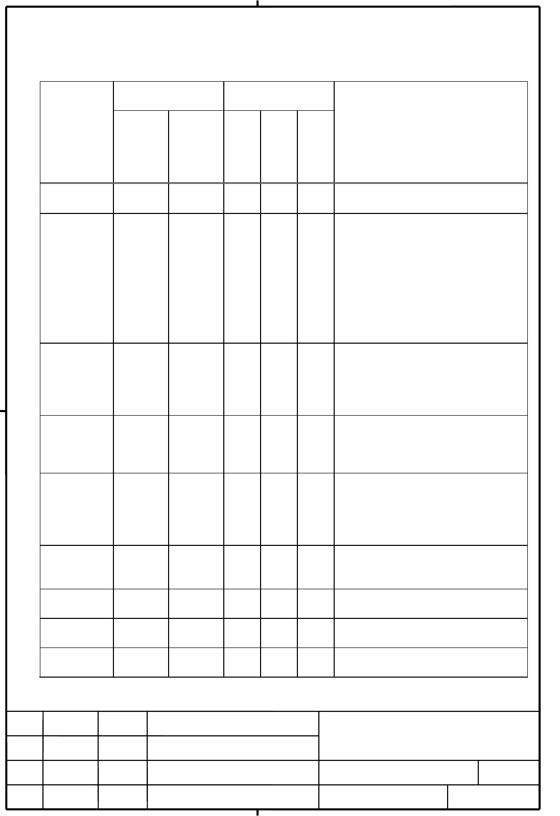
8. Dealing with errors
Check error status on the LED display or on the I/O Link.
alarm or
warning
LED indicator status signal on I/O
Link
Possible cause, dealing with errors
LED 7
segments
LED
ERR
X+18
bit 1
AS-i
data
ready
X+18
bit 0
else
normal
operation
- off 0 1 - -
configuration
mismatch
CER lit (note 1) 0 1 X+16
bit7=0
Current configuration does not match
configured configuration.
When the protected mode, use the
DISP switch to check the mismatch
slave address.
The possible cause are slave unit
failure, disconnection of AS-i cable,
communication error caused by the
noise.
during
initialization,
changing
mode,
- 88 0 0 X+16
bit0=1
or
X+17
bit0=1
-
AS-i power
supply fail
APF lit 88 1 0 X+16
bit1=1
Check the AS-i power supply and AS-i
cable.
This status is restored when the AS-i
power is normal.
AS-i master
internal
EEPROM fail
ERR lit E1 1 0 X+17
bit2=0
Turn on the power again. Because the
configuration may be failed, set to
configure again. If the alarm is occurred
again, replace the converter unit.
Refer to note 5) of next page.
AS-i master
fail
ERR lit E0 1 0 X+18
bit2=1
Turn on the power again. If the alarm is
occurred again, replace the converter
unit
ROM fail ERR lit E2 1 0 X+18
bit3=1
Replace the converter unit.
RAM fail ERR lit E3 1 0 X+18
bit4=1
Replace the converter unit.
Watch Dog
alarm 1
ERR lit E8 1 0 X+18
bit5=1
Replace the converter unit.
EDIT
FANUC LTD
SHEET
DRAW. NO.
CUST
TITLE
29/33
DESCRIPTION DESIG. DATE
04 05.06.07 Yamana Out of frame #4 is added
FANUC I/O Link-AS-i Converter
Connecting manual
A
-80906E
#4
Contents Summary of FANUC I/O Link-AS-i Converter Connecting Manual Additional Manual
- Page 1FANUC I/O Link-AS-i Converter Connecting manual Table of contents 1.Outline 1.1 Strong point #2 1.2 Version of AS-i 6.Command execution by the ladder program 1.3 Ordering specification 6.1 Commands that can be executed from the #2 1.4 Applicable CNCs ladder program 1.5 Specification of I/O Link side
- Page 21.Outline FANUC I/O Link-AS-i converter is stand alone unit which converts from FANUC I/O Link (omit as I/O Link) to AS-i interface (omit as AS-i). 1.1 Strong point This unit converts form AS-i to I/O Link. And it makes possible to use DI/DO signals of AS-i slaves on PMC which is provided with CNC v
- Page 31.5 Specification of I/O Link side For Ver. 2.0 For Ver. 2.1 A03B-0817-C001 A03B-0817-C002 #2 Occupied I/O points DI:256 points, DO:256 points DI:512 points, DO:512 points Note) It is necessary to assign two groups continuously. 1.6 Correspondence of AS-i profile #2 For Ver. 2.0 For Ver. 2.1 A03B-08
- Page 42.Installation 2.1 Environmental conditions I/O Link-AS-i converter has been designed on the assumption that they are housed in closed cabinets. The environmental conditions when installing these cabinets shall conform to the following. (1) Surrounding temperature During operation : 0 to 55ºC During
- Page 52.3 Arrangement of connector AS-i terminal 2.4 Installation 1) Cautions for mounting unit (1) Use the unit in a completely sealed cabinet. (2) Mount the unit on a vertical surface, and allow a space of at least 100 mm above and below the unit. Do not place any unit generating a large amount of heat
- Page 6CAUTION This unit requires a clearance on both sides for maintenance purposes to accommodate a screwdriver inserted obliquely when the detector interface unit is mounted or removed. As a guideline, allow a gap of at least about 20mm between this unit and each adjacent unit if the detector interface
- Page 73)Using DIN rail for mounting How to mount DIN rail 1.Place the hook of the unit on the top end of the DIN rail 2.Push in the unit firmly until it clicks. How to remove DIN rail 1. Pull down the look on the unit using a flat-blade screwdriver or similar object. 2. Remove the unit by pulling bottom t
- Page 83.Connection 3.1 General connection diagram CNC FANUC I/O Link I/O Link JD1A CP1_A JD1B JD1A DC24V JD1B JD1A Power Supply AS-i Converter Such as I/O Unit CP1 Terminal #2 CP1_B External AS-i cable device AS-i power AS-i slave AS-i slave 3.2 Connecting Input power source Supply power to this unit from
- Page 9The 24V DC input to CP1(A1,A2) can be output from CP1(B1,B2) for use branchimg. The connection of CP1(B1,B2) is as shown below. In this case, the external 24V DC power supply #2 should have a rating which is equal to the sum of the current consumed by the control unit and the current used via CP1(B1
- Page 103.3Power turn-on sequence Turn on the power to this unit in the following order or simultaneously. However it is possible to turn-on of AS-i power which connects with AS-i communication cable at any time in spite of the following order. 1. Power supplies (200 VAC) for the entire machine (including t
- Page 113.5 Connection of the FANUC I/O Link Please refer to connecting manual of control unit that AS-i converter is connected. The way to connect of unit which is connected I/O Link is common completely. 3.6 Connection of AS-i terminal Screw for detachable terminal +:Brown Two sets of "+" terminal AS-i ca
- Page 124. DI/DO map on the I/O Link 4.1 For AS-i ver. 2.0 (A03B-0817-C001) Assign 32 byte input and 32 byte output on the I/O Link Assign name : input OC03I, output OC03O
- Page 134.2 For AS-i ver. 2.1 (A03B-0817-C002) Assign 64 byte input and 64 byte output on the I/O Link Assign name : input OC03I, output OC03O #2 (It is necessary to assign two groups continuously.) Group XX Group XX+1 X bit 7-4 bit 3-0 X' bit 7-4 bit 3-0 +0 DI #1A Reserved +0 DI #1B Reserved +1 DI
- Page 14
- Page 155. Details of I/O Link DI/DO 5.1 input / output data area 5.1.1 For AS-i ver. 2.0 (A03B-0817-C001) Signal input is assigned on from X+0 to X+15, signal output is assigned on from Y+0 to Y+15. 1 means ON state and 0 means OFF state. address bit 7 bit 6 bit 5 bit 4 bit 3 bit 2 bit 1 bit 0 X+0 DI of sl
- Page 165.1.2 For AS-i ver. 2.1 (A03B-0817-C002) Signal input is assigned on from X+0 to X+15 (group XX) and from X'+0 to X'+15 (group #2 XX+1), signal output is assigned on from Y+0 to Y+15 (group XX) and from Y'+0 to Y'+15 (group XX+1). 1 means ON state and 0 means OFF state. address bit 7 bit 6 b
- Page 175.2 AS-i master status address bit item bit status Condition of flag on X+16 0 Off line phase status 1 : off line When the off line phase is 0 : not off line active; configuring process is executed, or AS-i power supply fail 1 AS-i power supply 1 : Voltage on AS-i line is AS-i power supply is off or
- Page 185.4 List of slave Output signals on the list of slave area (address X+20 - X+23. In case of AS-i ver 2.1, address X'20 - X'23 are included.) is changed according to the list output mode setting parameter (Y+16 bit 6 and bit 7) (1) AS-i ver 2.0 address bit 7 bit 6 bit 5 bit 4 bit 3 bit 2 bit 1 bit 0
- Page 196. Command execution by the ladder program It can be done that reading and writing the parameters of the AS-i slave unit, changing the address, reading I/O configuration and ID code from the ladder program. 6.1 Commands that can be executed from the ladder program Command code Command Parameters rep
- Page 206.3 Details of command flag and status address bit contents Y+16 0 Request Flag 1 : Command is requested 1 Reserved 2 Reserved 3 Reserved 4 Reserved 5 Reserved 6 list output mode setting 7 00 : discrepancies between LPS and LES 01 : LES 10 : LAS 11 : LPS X+24 0 End Flag 1 : End of command 1 Error Fl
- Page 216.5 An order of command handshake Command code Command parameter Request flag End flag Error status Response data Execution of command (1) Application side : Check that request flag and end flag keep off, then write command code. If necessary, parameter data should be written at same time. Then set
- Page 226.6 Details of commands (1) A parameter value for the specified AS-i slave is transferred to EEPROM of AS-i converter. address bit 7 bit 6 bit 5 bit 4 bit 3 bit 2 bit 1 bit 0 Set data Y+17 0AH Y+18 Slave address(01H~1FH, 20H~3FH)Note1) Refer to 24page #2 Y+19 0 Parameter Y+20~Y+21 none Response X+25
- Page 23(5) Read actual I/O configuration data and actual ID codes of an addressed slave detected on the AS-i. address bit 7 bit 6 bit 5 bit 4 bit 3 bit 2 bit 1 bit 0 Set data Y+17 12H Y+18 Slave address(01H~1FH, 20H~3FH)Note1) Refer to 24page #2 Y+19~Y+21 none Response X+25 Error code data X+26 0 ID code X
- Page 24#2 (8) Analog output value is transferred to the specified AS-i slave address bit 7 bit 6 bit 5 bit 4 bit 3 bit 2 bit 1 bit 0 Set data Y+17 2AH Y+18 Slave address(01H~1FH) Note2) Refer as follows Y+19 26 Ch1output value (High byte) Y+20 27 Ch1 output value (Low byte) Y+21 28 Ch2 output value (High b
- Page 257. LED display and setting switch operation (1)LED (2) 7 segment LED (3) Setting switch Note) This mark is only written in #2 AS-i converter whose ver. is 2.1. (4) AS-i terminal TITLE FANUC I/O Link-AS-i Converter Connecting manual DRAW. NO. CUST 02 02.11.22 Yamana Out of frame #2 is added A-80906E
- Page 267.1 LED display name color meaning Unit POW Green Power supply to the unit is on. ERR Red Unit Error (refer to the other LED, 7 segments LED display or status on the I/O Link about details of error) I/O Link RDY Green I/O Link Ready (I/O Link communication available) ALM Red I/O Link Alarm (refer to
- Page 27*The order of indication of slave address When slave address indicates on LED display, address of standard slave or A slave #2 ("."(dot) of X1 turns off) indicates prior to one of B slave ("."(dot) of X1 turns on). [example] address #10 standard slave address #20A A/B slave address #20B A/B slave ad
- Page 287.3 Setting switch Setting Operation mode switch Configuration mode Protected mode DISP Display the address number of the slave units (Next input of the setting switch is not accepted until the display of every slave is finished.) Display every attached slave units at Display every configuration abo
- Page 298. Dealing with errors Check error status on the LED display or on the I/O Link. alarm or LED indicator status signal on I/O Possible cause, dealing with errors warning Link LED 7 ERR AS-i else segments X+18 data LED bit 1 ready X+18 bit 0 normal - off 0 1 - - operation configuration CER lit (note 1
- Page 30Watch Dog ERR lit E9 or 1 0 - I/O Link system alarm is occurred on the Alarm 2 "."(dot) of host CNC. X10 Replace the converter unit. I/O Link ERR lit E6 - - - I/O Link system alarm is occurred on the slave watch host CNC. dog This error is occurred when the power of the other I/O Link slave unit is
- Page 319.How to use I/O Link - AS-i Converter 9.1 Installation These operations can be done when the I/O Link is not Start connected. (In other words, even if the power of I/O Link - AS-i Converter is turned on and Mount the I/O Link-AS-i Converter, AS-i the power of CNC is turned off, power supply and AS-
- Page 329.2 Normal operation (1) Operation mode The operation mode should be protected mode in the normal operation. In this protected mode, when the configuration mismatch is occurred by the cable disconnection, AS-i communication error, or the slave unit failure, CER LED lit and the mismatch slave is disp
- Page 3310. CE marking I/O Link-AS-i converter is applied to CE marking. Because I/O Link-AS-i converter is based on European Standard about AS-i (EN50295), this unit is not tested for surge immunity. 11. Fuse The unit has built-in fuse. If a fuse blows, remove the cause, then replace the fuse with a #2 spa