Series 20i-MODEL A Parameter manual Page 30
Parameter manual
4. DESCRIPTION OF PARAMETERS
B–63380EN/02
26
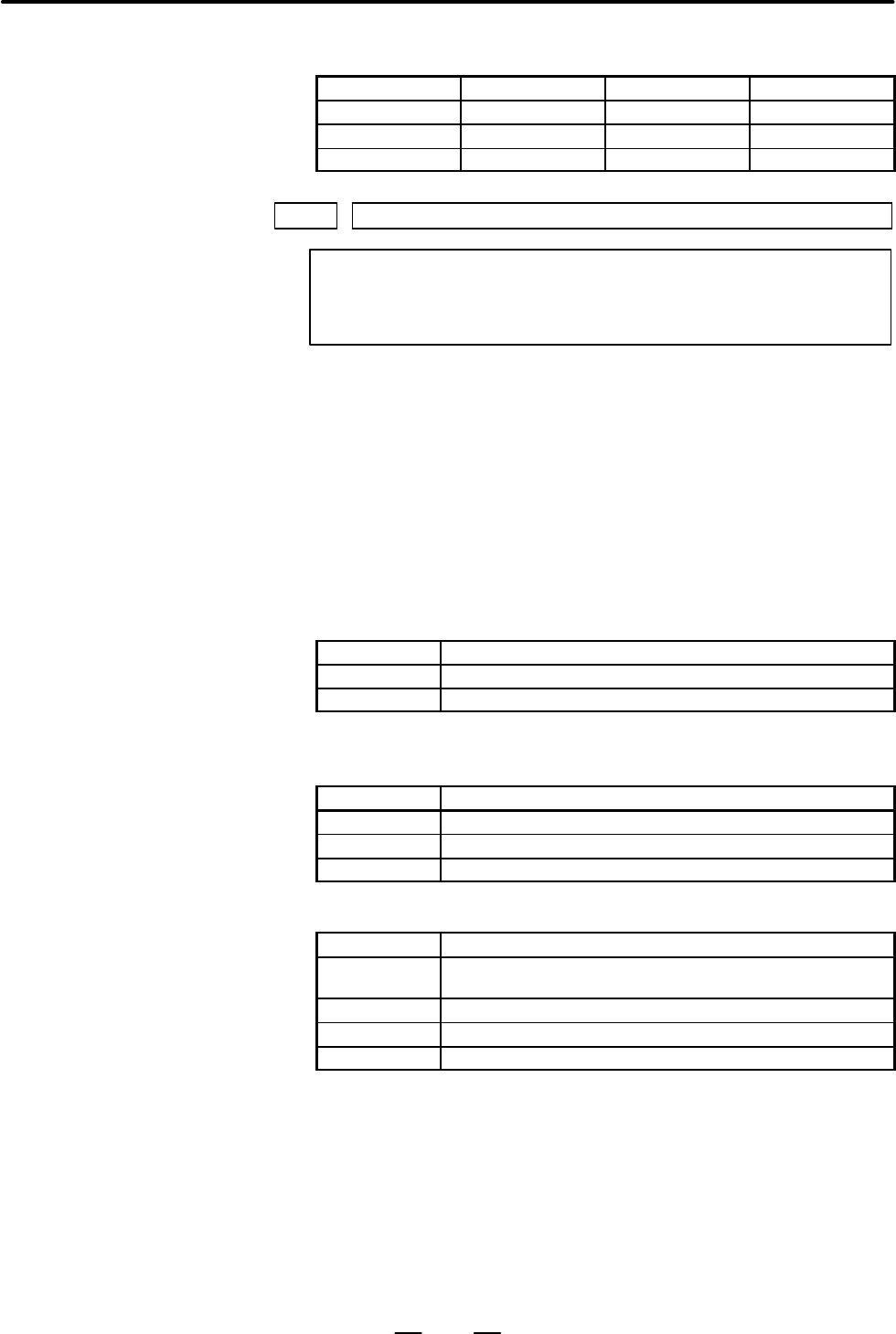
Set the axis name of the fourth axis as follows:
Axis name Setting Axis name Setting
U 85 A 65
V 86 B 66
W 87 C 67
1022 Setting of each axis in the basic coordinate system
NOTE
When this parameter is set, power must be turned off before
operation is continued.
[Data type] Byte axis
To determine the following planes used for circular interpolation, cutter
compensation C (for the F series), tool nose radius compensation (for the
T series), etc., each control axis is set to one of the basic three axes X, Y,
and Z, or an axis parallel to the X, Y, or Z axis.
G17: Plane Xp–Yp
G18: Plane Zp–Xp
G19: Plane Yp–Zp
T series: Set 1 for the first axis and 3 for the second axis.
Setting Meaning
1 X–axis of the basic two axes
2 Z–axis of the basic two axes
F series: Set 1 for the first axis, 2 for the second axis, and 3 for the third
axis.
Setting Meaning
1 X–axis of the basic three axes
2 Y–axis of the basic three axes
3 Z–axis of the basic three axes
Set a value in the following table for the fourth axis:
Setting Meaning
0
This axis is not one of the three basic axes and their parallel
axes.
5 Axis parallel to the X–axis
6 Axis parallel to the Y–axis
7 Axis parallel to the Z–axis
Contents Summary of Series 20i-MODEL A Parameter manual
- Page 1B–63380EN/02 DEFINITION OF WARNING, CAUTION, AND NOTE DEFINITION OF WARNING, CAUTION, AND NOTE This manual includes safety precautions for protecting the user and preventing damage to the machine. Precautions are classified into Warning and Caution according to their bearing on safety. Also, supplem
- Page 2PREFACE B–63380EN/02 PREFACE The mode covered by this manual, and their abbreviations are : Product Name Abbreviations FANUC Series 20i–TA 20i–TA Series 20i FANUC Series 20i–FA 20i–FA NOTE 1 For convenience of explanation, each model may be classified as follows: T series : 20i–TA F series : 20i–FA
- Page 3B–63380EN/02 Table of Contents DEFINITION OF WARNING, CAUTION, AND NOTE . . . . . . . . . . . . . . . . . . . . . . . . . . s–1 PREFACE . . . . . . . . . . . . . . . . . . . . . . . . . . . . . . . . . . . . . . . . . . . . . . . . . . . . . . . . . . . . . . . . p–1 1. DISPLAYING PARAMETERS . . . .
- Page 4Table of Contents B–63380EN/02 4.24 PARAMETERS OF DISPLAYING OPERATION TIME AND NUMBER OF PARTS . . . . . . . . . . 171 4.25 PARAMETERS OF MANUAL OPERATION AND AUTOMATIC OPERATION . . . . . . . . . . . . . 175 4.26 PARAMETERS OF MANUAL HANDLE FEED, HANDLE INTERRUPTION AND HANDLE FEED IN TOOL AXIAL D
- Page 5B–63380EN/02 1. DISPLAYING PARAMETERS 1 DISPLAYING PARAMETERS Follow the procedure below to display parameters. (1) Press the SYSTEM function key on the MDI as many times as required, or alternatively, press the SYSTEM function key once, then the PARAM section display soft key. The parameter screen
- Page 62. SETTING PARAMETERS FROM MDI B–63380EN/02 2 SETTING PARAMETERS FROM MDI Follow the procedure below to set parameters. (1) Place the NC in the MDI mode or the emergency stop state. (2) Follow the substeps below to enable writing of parameters. 1. To display the setting screen, press the
- Page 7B–63380EN/02 2. SETTING PARAMETERS FROM MDI [Example] 12000 [INPUT] PARAMETER (FEEDRATE) O0001 N00010 1401 RDR JZR RPD Cursor 0 0 0 0 0 0 0 0 1402 JRV 0 0 0 0 0 0 0 0 1410 DRY RUN FEEDRATE 12000 1412 0 1420 RAPID FEEDRATEX 15000 Y 15000 Z 15000 > MDI STOP *** *** ALM 10:03:10 [NO.SRH] [ ON:1 ] [ OFF
- Page 83. INPUTTING AND OUTPUTTING PARAMETERS THROUGH THE READER/PUNCHER INTERFACE B–63380EN/02 INPUTTING AND OUTPUTTING PARAMETERS THROUGH 3 THE READER/PUNCHER INTERFACE This section explains the parameter input/output procedures for input/output devices connected to the reader/puncher interface. The foll
- Page 93. INPUTTING AND OUTPUTTING PARAMETERS THROUGH B–63380EN/02 THE READER/PUNCHER INTERFACE 3.1 (1) Select the EDIT mode or set to Emergency stop. OUTPUTTING (2) To select the parameter screen, press the
function key PARAMETERS as many times as required, or alternatively press the fun - Page 103. INPUTTING AND OUTPUTTING PARAMETERS THROUGH THE READER/PUNCHER INTERFACE B–63380EN/02 3.2 (1) Place the NC in the emergency stop state. INPUTTING (2) Enable parameter writing. PARAMETERS 1. To display the setting screen, press the
THROUGH THE function key as many times as require - Page 11B–63380EN/02 4. DESCRIPTION OF PARAMETERS 4 DESCRIPTION OF PARAMETERS Parameters are classified by data type as follows: Table 4 Data Types and Valid Data Ranges of Parameters Data type Valid data range Remarks Bit 0 or 1 Bit axis Byte –128 to 127 In some parameters, signs are Byte axis 0 to 255 ign
- Page 124. DESCRIPTION OF PARAMETERS B–63380EN/02 NOTE 1 The bits left blank in 4. DESCRIPTION OF PARAMETERS and parameter numbers that appear on the display but are not found in the parameter list are reserved for future expansion. They must always be 0. 2 Parameters having different meanings between the T
- Page 13B–63380EN/02 4. DESCRIPTION OF PARAMETERS 4.1 #7 #6 #5 #4 #3 #2 #1 #0 PARAMETERS OF 0000 SEQ INI ISO TVC SETTING Setting entry is acceptable. [Data type] Bit TVC TV check 0 : Not performed 1 : Performed ISO Code used for data output 0 : EIA code 1 : ISO code INI Unit of input 0 : In mm 1 : In inches
- Page 144. DESCRIPTION OF PARAMETERS B–63380EN/02 #7 #6 #5 #4 #3 #2 #1 #0 0012 MIRx Setting entry is acceptable. [Data type] Bit axis MIRx Mirror image for each axis 0 : Mirror image is off. 1 : Mirror image is on. 0020 I/O CHANNEL: Selection of an input/output device Setting entry is acceptable. [Data type
- Page 15B–63380EN/02 4. DESCRIPTION OF PARAMETERS NOTE 1 An input/output device can also be selected using the setting screen. Usually, the setting screen is used. 2 The specifications (such as the baud rate and the number of stop bits) of the input/output devices to be connected must be set in the correspo
- Page 164. DESCRIPTION OF PARAMETERS B–63380EN/02 4.2 The parameters described below must be set when an input/output device interface (RS–232C serial port) or remote buffer interface is used to PARAMETERS OF transmit data (including programs and parameters) to and from an READER/PUNCHER external input/outp
- Page 17B–63380EN/02 4. DESCRIPTION OF PARAMETERS 4.2.1 Parameters Common to All Channels 0024 Port for communication with the PMC ladder development tool (FAPT LADDER–II) [Data type] Byte This parameter sets the port to be used for communication with the PMC ladder development tool (FAPT LADDER–II). 0 : Un
- Page 184. DESCRIPTION OF PARAMETERS B–63380EN/02 4.2.2 Parameters of Channel 1 #7 #6 #5 #4 #3 #2 #1 #0 (I/O CHANNEL=0) 0101 NFD ASI SB2 [Data type] Bit type SB2 The number of stop bits 0: 1 1: 2 ASI Code used at data input 0 : EIA or ISO code (automatically distinguished) 1 : ASCII code NFD Feed before and
- Page 19B–63380EN/02 4. DESCRIPTION OF PARAMETERS 0103 Baud rate (when the I/O CHANNEL is set to 0) [Data type] Byte Set baud rate of the input/output device used when the I/O CHANNEL is set to 0, with a set value in Table 4.2 (b). Table 4.2.2 (b) Set value Baud rate (bps) Set value Baud rate (bps) 1 50 7 6
- Page 204. DESCRIPTION OF PARAMETERS B–63380EN/02 4.2.4 Parameters of #7 #6 #5 #4 #3 #2 #1 #0 Channel 2 0121 NFD ASI SB2 (I/O CHANNEL=2) [Data type] Bit These parameters are used when I/O CHANNEL is set to 2. The meanings of the bits are the same as for parameter 0101. 0122 Number specified for the input/ou
- Page 21B–63380EN/02 4. DESCRIPTION OF PARAMETERS 0133 Baud rate (when the I/O CHANNEL is set to 3) NOTE When this parameter is set, the power must be turned off before operation is continued. [Data type] Byte Set the baud rate of the input/output device used when the I/O CHANNEL is set to 3 according to th
- Page 224. DESCRIPTION OF PARAMETERS B–63380EN/02 #7 #6 #5 #4 #3 #2 #1 #0 0135 RMS R42 PRA ETX ASC NOTE When this parameter is set, the power must be turned off before operation is continued. [Data type] Bit ASC Communication code except NC data 0: ISO code 1: ASCII code ETX End code for protocol A or exten
- Page 23B–63380EN/02 4. DESCRIPTION OF PARAMETERS 4.3 PARAMETERS OF POWER MOTION #7 #6 #5 #4 #3 #2 #1 #0 MANAGER 0960 PMN MD2 MD1 SLV [Data type] Bit SLV When the power motion manager is selected, the screen displays: 0 : One slave. 1 : Up to four slaves with the screen divided into four. MD1,MD2 These para
- Page 244. DESCRIPTION OF PARAMETERS B–63380EN/02 4.4 PARAMETERS OF AXIS CONTROL/ INCREMENT SYSTEM #7 #6 #5 #4 #3 #2 #1 #0 1001 INM NOTE When this parameter is set, the power must be turned off before operation is continued. [Data type] Bit INM Least command increment on the linear axis 0 : In mm (metric sy
- Page 25B–63380EN/02 4. DESCRIPTION OF PARAMETERS XIK When LRP, bit 1 of parameter No.1401, is set to 0, namely, when positioning is performed using non–linear type positioning, if an interlock is applied to the machine along one of axes in positioning, 0: The machine stops moving along the axis for which t
- Page 264. DESCRIPTION OF PARAMETERS B–63380EN/02 #7 #6 #5 #4 #3 #2 #1 #0 DLZx ZRNx 1005 HJZx DLZx ZRNx [Data type] Bit axis ZRNx When a command specifying the movement except for G28 is issued in automatic operation (MEM, RMT, or MDI) and when a return to the reference position has not been performed since
- Page 27B–63380EN/02 4. DESCRIPTION OF PARAMETERS #7 #6 #5 #4 #3 #2 #1 #0 ZMIx DIAx 1006 ZMIx ROSx ROTx NOTE When this parameter is set, the power must be turned off before operation is continued. [Data type] Bit axis ROTx, ROSx Setting linear or rotation axis. ROSx ROTx Meaning 0 0 Linear axis (1) Inch/met
- Page 284. DESCRIPTION OF PARAMETERS B–63380EN/02 #7 #6 #5 #4 #3 #2 #1 #0 1008 RRLx RABx ROAx NOTE When this parameter is set, the power must be turned off before operation is continued. [Data type] Bit axis ROAx The roll–over function of a rotation axis is 0 : Invalid 1 : Valid NOTE ROAx specifies the func
- Page 29B–63380EN/02 4. DESCRIPTION OF PARAMETERS [Examples] Suppose that the first axis is the X axis, and the second and subsequent axes are the Y, Z, and A axes in that order, and that they are controlled as follows: X, Y, and Z axes: Controlled by the CNC and PMC A axis: Controlled by the PMC Then set t
- Page 304. DESCRIPTION OF PARAMETERS B–63380EN/02 Set the axis name of the fourth axis as follows: Axis name Setting Axis name Setting U 85 A 65 V 86 B 66 W 87 C 67 1022 Setting of each axis in the basic coordinate system NOTE When this parameter is set, power must be turned off before operation is continue
- Page 31B–63380EN/02 4. DESCRIPTION OF PARAMETERS 1023 Number of the servo axis for each axis NOTE When this parameter is set, power must be turned off before operation is continued. [Data type] Byte axis [Valid data range] 1, 2, ..., number of control axes Set the servo axis for each control axis. Usually
- Page 324. DESCRIPTION OF PARAMETERS B–63380EN/02 4.5 #7 #6 #5 #4 #3 #2 #1 #0 PARAMETERS OF ZPI ZPR 1201 COORDINATES AWK ZCL ZPI ZPR [Data type] Bit ZPR Automatic setting of a coordinate system when the manual reference position return is performed 0 : Not set automatically 1 : Set automatically This bit is
- Page 33B–63380EN/02 4. DESCRIPTION OF PARAMETERS #7 #6 #5 #4 #3 #2 #1 #0 1202 AWN G52 RLC [Data type] Bit RLC Local coordinate system is 0 : Not cancelled by reset 1 : Cancelled by reset G52 In local coordinate system setting (G52), a cutter compensation vector is: 0 : Not considered. 1 : Considered. NOTE
- Page 344. DESCRIPTION OF PARAMETERS B–63380EN/02 1221 Workpiece zero point offset value in workpiece coordinate system 1 (G54) 1222 Workpiece zero point offset value in workpiece coordinate system 2(G55) 1223 Workpiece zero point offset value in workpiece coordinate system 3(G56) 1224 Workpiece zero point
- Page 35B–63380EN/02 4. DESCRIPTION OF PARAMETERS Coordinate value of the reference position on each axis in the machine 1240 coordinate system NOTE When this parameter is set, power must be turned off before operation is continued. Coordinate value of the second reference position on each axis in the machi
- Page 364. DESCRIPTION OF PARAMETERS B–63380EN/02 1260 Amount of a shift per one rotation of a rotation axis NOTE When this parameter is set, the power must be turned off before operation is continued. [Data type] 2–word axis [Unit of data] Increment system Unit of data Standard value IS–B 0.001 deg 360000
- Page 37B–63380EN/02 4. DESCRIPTION OF PARAMETERS 4.6 PARAMETERS OF #7 #6 #5 #4 #3 #2 #1 #0 STROKE CHECK 1300 BFA LZR LMS BFA LZR LMS OUT [Data type] Bit OUT The area inside or outside of the stored stroke check 2 is set by parameters (No. 1322, 1323) as an inhibition area. 0 : Inside 1 : Outside LMS The EX
- Page 384. DESCRIPTION OF PARAMETERS B–63380EN/02 1320 Coordinate value I of stored stroke check 1 in the positive direction on each axis 1321 Coordinate value I of stored stroke check 1 in the negative direction on each axis [Data type] 2–word axis Increment system IS–B IS–C Unit Millimeter machine 0.001 0
- Page 39B–63380EN/02 4. DESCRIPTION OF PARAMETERS [Valid data range] –99999999 to 99999999 Set the coordinate values of stored stroke check 2 in the positive and negative directions foreach axis in the machine coordinate system. OUT, #0 of parameter 1300, sets either the area outside of the area inside spec
- Page 404. DESCRIPTION OF PARAMETERS B–63380EN/02 4.7 PARAMETERS OF #7 #6 #5 #4 #3 #2 #1 #0 FEEDRATE RDR TDR RF0 JZR LRP RPD 1401 RDR TDR RF0 LRP RPD [Data type] Bit RPD Manual rapid traverse during the period from power–on time to the completion of the reference position return. 0 : Disabled (Jog feed is p
- Page 41B–63380EN/02 4. DESCRIPTION OF PARAMETERS JRV Jog feed and incremental feed mode 0 : Feed per minute (Set the feed amount per minute for parameters Nos. 1410 and 1423.) 1 : Feed per revolution (Set the feed amount per spindle rotation for parameters Nos. 1415 and 1423.) NOTE Specify a feedrate in pa
- Page 424. DESCRIPTION OF PARAMETERS B–63380EN/02 DLF After a reference potition is set, manual reference position return performed at: 0 : Rapid traverse rate (parameter No.1420) 1 : Manual rapid traverse rate (parameter No.1424) NOTE This parameter selects a feedrate for reference position return performe
- Page 43B–63380EN/02 4. DESCRIPTION OF PARAMETERS FRV For inch input, the valid range of the feedrate specified for feed per revolution is: 0 : Standard range. (F0.000001 to 9.999999 inches per revolution) 1 : Extended to F50.0 inches per revolution. (F0.000001 to 50.000000 inches per revolution) #7 #6 #5 #
- Page 444. DESCRIPTION OF PARAMETERS B–63380EN/02 When the machine requires little change in cutting feedrate during cutting, a cutting feedrate can be specified in the parameter. This eliminates the need to specify a cutting feedrate in the NC program. The feedrate set in this parameter is effective betwee
- Page 45B–63380EN/02 4. DESCRIPTION OF PARAMETERS Set the F0 rate of the rapid traverse override for each axis. Rapid traverse override signal Override value ROV2 ROV1 0 0 100% 0 1 50% 1 0 25% 1 1 F0 F0: Parameter 1421 1422 Maximum cutting feedrate for all axes [Data type] 2–word [Unit of data] Valid data r
- Page 464. DESCRIPTION OF PARAMETERS B–63380EN/02 1424 Manual rapid traverse rate for each axis [Data type] 2–word axis [Unit of data] Valid data range Increment system Unit of data IS-B IS-C [Valid data range] Millimeter machine 1 mm/min 30 to 240000 30 to 100000 Inch machine 0.1 inch/min 30 to 96000 30 to
- Page 47B–63380EN/02 4. DESCRIPTION OF PARAMETERS 1431 Maximum cutting feedrate for all axes in the look–ahead control mode [Data type] 2–words [Unit of data, valid range] Valid data range Increment system Unit of data IS-B IS-C Millimeter machine 1 mm/min 0 to 240000 0 to 100000 Inch machine 0.1 inch/min 0
- Page 484. DESCRIPTION OF PARAMETERS B–63380EN/02 4.8 PARAMETERS OF #7 #6 #5 #4 #3 #2 #1 #0 ACCELERATION/ NCI RTO DECELERATION 1601 NCI RTO OVB CONTROL [Data type] Bit OVB Block overlap in cutting feed 0 : Blocks are not overlapped in cutting feed. 1 : Blocks are overlapped in cutting feed. Block overlap ou
- Page 49B–63380EN/02 4. DESCRIPTION OF PARAMETERS #7 #6 #5 #4 #3 #2 #1 #0 1602 LS2 CSD BS2 COV FWB [Data type] Bit FWB Cutting feed acceleration/deceleration before interpolation 0 : Type A of acceleration/deceleration before interpolation is used. 1 : Type B of acceleration/deceleration before interpolatio
- Page 504. DESCRIPTION OF PARAMETERS B–63380EN/02 CSD In the function for automatically reducing a feedrate at corners, 0 : Angles are used for controlling the feedrate. 1 : Differences in feedrates are used for controlling the feedrate. LS2 Acceleration/deceleration after interpolation for cutting feed in
- Page 51B–63380EN/02 4. DESCRIPTION OF PARAMETERS 1620 Time constant used for linear acceleration/deceleration or bell–shaped accelera- tion/deceleration in rapid traverse for each axis [Data type] Word axis [Unit of data] ms [Valid data range] 0 to 4000 Specify a time constant used for linear acceleration/
- Page 524. DESCRIPTION OF PARAMETERS B–63380EN/02 1623 FL rate of exponential acceleration/deceleration in cutting feed for each axis [Data type] Word axis [Unit of data] Valid data range Increment system Unit of data IS-A, IS-B IS-C [Valid data range] Millimeter machine 1 mm/min 0,6 to 15000 0,6 to 12000 I
- Page 53B–63380EN/02 4. DESCRIPTION OF PARAMETERS FL rate of exponential acceleration /deceleration in the thread cutting cycle for 1627 each axis [Data type] Word axis [Unit of data] Valid data range Increment system Unit of data IS-B IS-C [Valid data range] Millimeter machine 1 mm/min 6 to 15000 6 to 1200
- Page 544. DESCRIPTION OF PARAMETERS B–63380EN/02 1711 Angle (θp) to recognize the inner corner in override [Data type] Byte [Unit of data] Degree [Valid data range] 1 to 179 (standard value = 91) This parameter sets the angle used to recognize an inner corner for inner corner override by automatic corner o
- Page 55B–63380EN/02 4. DESCRIPTION OF PARAMETERS Ls and Le are set in parameters 1713 and 1714. Ls Le θ b Programmed a path Cutter center path An override is applied from point a to b. Fig.4.8 (b) Distance Le and Ls in the automatic corner override at an inner corner 1722 Rapid traverse feedrate reduction
- Page 564. DESCRIPTION OF PARAMETERS B–63380EN/02 1762 Exponential acceleration/deceleration time constant for cutting feed in the look– ahead control mode [Data type] Word axis [Unit of data] 1 ms [Valid data range] 0 to 4000 Set an exponential acceleration/deceleration time constant for cutting feed in th
- Page 57B–63380EN/02 4. DESCRIPTION OF PARAMETERS This parameter is used to set an acceleration for linear acceleration/ deceleration before interpolation in the look–ahead control mode. In this parameter, set the maximum machining speed during linear acceleration/ deceleration before interpolation. Set the
- Page 584. DESCRIPTION OF PARAMETERS B–63380EN/02 1777 Minimum speed for the automatic corner deceleration function (look–ahead control) [Data type] Word axis [Unit of data, valid range] Valid data range Increment system Unit of data IS-B IS-C Millimeter machine 1 mm/min 6 to 15000 6 to 12000 Inch machine 0
- Page 59B–63380EN/02 4. DESCRIPTION OF PARAMETERS 1783 Allowable speed difference for the speed difference based corner deceleration function (linear acceleration/deceleration before interpolation) [Data type] Word axis [Unit of data, valid range] Valid range Increment system Unit of data IS-B IS-C Millimet
- Page 604. DESCRIPTION OF PARAMETERS B–63380EN/02 4.9 #7 #6 #5 #4 #3 #2 #1 #0 PARAMETERS OF 1800 TRC RBK FFR OZR CVR SERVO [Data type] Bit CVR When velocity control ready signal VRDY is set ON before position control ready signal PRDY comes ON 0: A servo alarm is generated. 1: A servo alarm is not generated
- Page 61B–63380EN/02 4. DESCRIPTION OF PARAMETERS #7 #6 #5 #4 #3 #2 #1 #0 TQA TQI 1803 TQF TQA TQI [Data type] Bit TQI While torque restriction is applied, in–position check is: 0 : Performed. 1 : Not performed. TQA While torque restriction is applied, checking for an excessive error in the stopped state/du
- Page 624. DESCRIPTION OF PARAMETERS B–63380EN/02 NOTE 3 The backlash acceleration function is disabled during manual operation for which manual circular interpolation is not specified (for example, manual linear interpolation or handle or jog feed along each axis). 4 When bit 6 of parameter No. 2009 (BLCUT
- Page 63B–63380EN/02 4. DESCRIPTION OF PARAMETERS #7 #6 #5 #4 #3 #2 #1 #0 1815 APCx APZx OPTx NOTE When this parameter has been set, the power must be turned off before operation is continued. [Data type] Bit axis OPTx Position detector 0 : A separate pulse coder is not used. 1 : A separate pulse coder is u
- Page 644. DESCRIPTION OF PARAMETERS B–63380EN/02 NOTE When the flexble feed gear is used, do not use these parameters. Set the numerator and denominator of DMR to an appropriate values in parameters 2084 and 2085 respectively. #7 #6 #5 #4 #3 #2 #1 #0 CRFx FUPx 1819 NAHx CRFx FUPx [Data type] Bit axis FUPx
- Page 65B–63380EN/02 4. DESCRIPTION OF PARAMETERS (1) T series Least Least input increment command increment IS–B Millimeter Millimeter 0.001 mm (diameter specification) 0.0005 mm machine input 0.001 mm (radius specification) 0.001 mm Inch input 0.0001 inch (diameter specification) 0.0005 mm 0.0001 inch (ra
- Page 664. DESCRIPTION OF PARAMETERS B–63380EN/02 (1) When command multiplier is 1/2 to 1/27 Set value = 1 + 100 (Command multiplier) Valid data range: 102 to 127 (2) When command multiply is 1 to 48 Set value = 2 command multiplier Valid data range: 2 to 96 NOTE When command multiplier is 1 to 48, the set
- Page 67B–63380EN/02 4. DESCRIPTION OF PARAMETERS 1826 In–position width for each axis [Data type] Word axis [Unit of data] Detection unit [Valid data range] 0 to 32767 The in–position width is set for each axis. When the deviation of the machine position from the specified position (the absolute value of t
- Page 684. DESCRIPTION OF PARAMETERS B–63380EN/02 1830 Axis–by–axis positional deviation limit at servo–off time [Data type] 2–word axis [Unit of data] Detection unit [Valid data range] 0 to 99999999 This parameter is used to set a positional deviation limit at servo–off time, on an axis–by–axis basis. If t
- Page 69B–63380EN/02 4. DESCRIPTION OF PARAMETERS To shift the reference position, the grid can be shifted by the amount set in this parameter. Up to the maximum value counted by the reference counter can be specified as the grid shift. 1851 Backlash compensating value for each axis [Data type] Word axis [U
- Page 704. DESCRIPTION OF PARAMETERS B–63380EN/02 NOTE 1 Jog feed is regarded as cutting feed. 2 The backlash compensation depending on a rapid traverse and a cutting feed is not performed until the first reference position return is completed after the power is turned on. The normal backlash compensation i
- Page 71B–63380EN/02 4. DESCRIPTION OF PARAMETERS 1877 Amount of inductosyn shift NOTE When this parameter has been set, the power must be turned off before operation is continued. [Data type] Word axis [Unit of data] Detection unit [Valid data range] –32767 to 32767 Set the amount of inductosyn shift for e
- Page 724. DESCRIPTION OF PARAMETERS B–63380EN/02 Example: Assume that the following settings have been made. If an abnormal load is detected for the sixth axis, movement along the second, fourth, sixth, and seventh axes is stopped. If an abnormal load is detected for the fourth axis, movement along the fou
- Page 73B–63380EN/02 4. DESCRIPTION OF PARAMETERS 1886 Positional deviation when torque control is canceled [Data type] Word axis [Unit of data] Detection unit [Valid data range] 0 to 32767 This parameter sets the positional deviation used when torque control, performed for an axis according to the axis con
- Page 744. DESCRIPTION OF PARAMETERS B–63380EN/02 #7 #6 #5 #4 #3 #2 #1 #0 1904 DSP NOTE After this parameter has been set, the power must be turned off then back on for the setting to become effective. [Data type] Bit axis DSP 0 : Two axes use one DSP. (Ordinary axes) 1 : One axis uses one DSP. (Axes such a
- Page 75B–63380EN/02 4. DESCRIPTION OF PARAMETERS CNC Controlled Program Servo axis Interface axis axis name number type number No.1020 No.1023 Fast/Slow 1 X 1 F 2–axis X (Fast) 2 Y 3 F amplifier 3 Z 4 S A (Slow) 4 A 2 S 1–axis Y (Fast) amplifier 1–axis Z (Slow) amplifier PM1 The first pulse module is: 0 :
- Page 764. DESCRIPTION OF PARAMETERS B–63380EN/02 These parameters set address conversion table values for slaves 1 to 10. A slave is the generic name given to a device such as a servo amplifier or pulse module, connected to the CNC via an FSSB optical cable. Smaller numbers, starting from 1 are assigned to
- Page 77B–63380EN/02 4. DESCRIPTION OF PARAMETERS S Examples of axis configurations and parameter settings CNC Controlled Program Servo axis Slave ATR axis axis name number number No.1910 Axis number No.1020 No.1023 to 1919 1 X 1 2 Y 3 1–axis 1 0 X 3 Z 4 amplifier 4 A 2 2 1 A 2–axis amplifier 3 2 Y M1 4 16
- Page 784. DESCRIPTION OF PARAMETERS B–63380EN/02 1920 Controlled axis number for slave 1 (dedicated to the FSSB setting screen) 1921 Controlled axis number for slave 2 (dedicated to the FSSB setting screen) 1922 Controlled axis number for slave 3 (dedicated to the FSSB setting screen) 1923 Controlled axis
- Page 79B–63380EN/02 4. DESCRIPTION OF PARAMETERS 1936 Connector number of the first pulse module 1937 Connector number of the second pulse module NOTE After these parameters have been set, the power must be turned off then back on for the settings to become effective. [Data type] Byte axis [Valid data rang
- Page 804. DESCRIPTION OF PARAMETERS B–63380EN/02 No. Data type Contents 2000 Bit axis PGEX PRMC DGPR PLC0 2001 Bit axis AMR7 AMR6 AMR5 AMR4 AMR3 AMR2 AMR1 AMR0 2002 Bit axis VFSE PFSE 2003 Bit axis V0FS OVSC BLEN NPSP PIEN OBEN TGAL 2004 Bit axis DLY0 2005 Bit axis SFCM BRKC FEED 2006 Bit axis DCBE ACCF SP
- Page 81B–63380EN/02 4. DESCRIPTION OF PARAMETERS No. Data type Contents 2053 Word axis Current dead zone compensation (PPMAX) 2054 Word axis Current dead zone compensation (PDDP) 2055 Word axis Current dead zone compensation (PHYST) 2056 Word axis Counterelectromotive force compensation (EMFCMP) 2057 Word
- Page 824. DESCRIPTION OF PARAMETERS B–63380EN/02 No. Data type Contents 2103 Word axis Amount of track back upon detection of unexpected disturbance torque 2104 Word axis Threshold for detecting abnormal load during cutting 2105 Word axis Torque constant 2109 Word axis Fine acceleration/deceleration time c
- Page 83B–63380EN/02 4. DESCRIPTION OF PARAMETERS 4.10 #7 #6 #5 #4 #3 #2 #1 #0 PARAMETERS OF 3001 MHI RWM DI/DO [Data type] Bit RWM RWD signal indicating that rewinding is in progress 0 : Output only when the tape reader is being rewound by the reset and rewind signal RRW 1 : Output when the tape reader is
- Page 844. DESCRIPTION OF PARAMETERS B–63380EN/02 If, however, a parameter specifies not to make in–position during deceleration, the signal turns to “0” at the end of deceleration. #7 #6 #5 #4 #3 #2 #1 #0 3004 OTH BCY BSL [Data type] Bit BSL The block start interlock signal *BSL and cutting block start int
- Page 85B–63380EN/02 4. DESCRIPTION OF PARAMETERS 3010 Time lag in strobe signals MF, SF and TF [Data type] Word [Unit of data] 1 ms [Valid data range] 16 to 32767 The time required to send strobe signals MF, SF and TF after the M, S, and T codes are sent, respectively. M, S, T code MF, SF TF signal Delay t
- Page 864. DESCRIPTION OF PARAMETERS B–63380EN/02 3017 Output time of reset signal RST [Data type] Byte [Unit of data] 16 ms [Valid data range] 0 to 255 To extend the output time of reset signal RST, the time to be added is specified in this parameter. RST signal output time = time veguired for reset + para
- Page 87B–63380EN/02 4. DESCRIPTION OF PARAMETERS 4.11 PARAMETERS OF #7 #6 #5 #4 #3 #2 #1 #0 MDI, DISPLAY, 3100 CEM AND EDIT [Data type] Bit CEM On screens such as the operation history screen and help screen, keys on the MDI panel are indicated: 0 : In English. 1 : With graphics qualifying for CE marking.
- Page 884. DESCRIPTION OF PARAMETERS B–63380EN/02 These operations are used for maintenance when the MDI panel has neither cursor nor page keys. Operation: Press a numeric key while holding down
. + 8: Same as cursor key ↑ . + 2: Same as cursor key ↓ . + 4: Same as cursor key ← . - Page 89B–63380EN/02 4. DESCRIPTION OF PARAMETERS [Data type] Bit These bits select the language to be used for the display. POR SPN HNG ITA CHI FRN GRM JPN Language 0 0 0 0 0 0 0 0 English 0 0 0 0 0 0 0 1 Japanese 0 0 0 0 0 0 1 0 German 0 0 0 0 0 1 0 0 French 0 0 0 0 1 0 0 0 Chinese 0 0 0 1 0 0 0 0 Italian
- Page 904. DESCRIPTION OF PARAMETERS B–63380EN/02 NOTE When tool geometry compensation of the T series is to be performed by shifting the coordinate system (with bit 4 (LGT) of parameter No.5002 set to 0), the programmed position, ignoring tool offset, is displayed (with this parameter set to 1), but the pr
- Page 91B–63380EN/02 4. DESCRIPTION OF PARAMETERS NOTE For each setting, movement along any axis other than those controlled by the CNC (see the description of parameter No. 1010) is not reflected in the actual speed display. DPS Actual spindle speed and T code 0 : Not always displayed 1 : Always displayed
- Page 924. DESCRIPTION OF PARAMETERS B–63380EN/02 #7 #6 #5 #4 #3 #2 #1 #0 JSP SLM WCI 3108 JSP SLM WCI PCT [Data type] Bit PCT On the 7–pieces type soft key display program check screen, T code displayed 0 : is a T code specified in a program (T). 1 : is a T code specified by the PMC (HD. T/NX. T) WCI On th
- Page 93B–63380EN/02 4. DESCRIPTION OF PARAMETERS #7 #6 #5 #4 #3 #2 #1 #0 RHD IKY DWT 3109 RHD IKY [Data type] Bit DWT Characters G and W in the display of tool wear/geometry compensation amount 0 : The characters are displayed at the left of each number. 1 : The characters are not displayed. IKY On the too
- Page 944. DESCRIPTION OF PARAMETERS B–63380EN/02 NPA Action taken when an alarm is generated or when an operator message is entered 0 : The display shifts to the alarm or message screen. 1 : The display does not shift to the alarm or message screen. #7 #6 #5 #4 #3 #2 #1 #0 3112 OPH EAH OMH SGD NOTE When th
- Page 95B–63380EN/02 4. DESCRIPTION OF PARAMETERS NOTE When the values of MS0 and MS1 are changed, all preserved external operator message history data is cleared. #7 #6 #5 #4 #3 #2 #1 #0 3114 IUS IMS ISY IOF IPR IPO [Data type] Bit IPO When the
function key is pressed while the position display scree - Page 964. DESCRIPTION OF PARAMETERS B–63380EN/02 NOTE Even if the PCF parameter (bit 1 of parameter No.3105) is set to 0, so as to add PMC controlled axis movement data to the actual speed display, the movement data for a PMC controlled axis for which NDFx is set to 1 is not added to the actual speed displ
- Page 97B–63380EN/02 4. DESCRIPTION OF PARAMETERS #7 #6 #5 #4 #3 #2 #1 #0 AS1 3118 [Data type] Bit AS1 When the actual spindle speed (SACT) of the first spindle is displayed, each value is: 0 : The value calculated based on the feedback pulses from the position coder. 1 : The value calculated from the spind
- Page 984. DESCRIPTION OF PARAMETERS B–63380EN/02 #7 #6 #5 #4 #3 #2 #1 #0 3124 D08 D07 D06 D05 D04 D03 D02 D01 3125 D16 D15 D14 D13 D12 D11 D10 D09 3126 D24 D23 D22 D21 D20 D19 D18 D17 3127 D25 [Data type] Bit Dxx (xx: 01 to 25) When modal G code is displayed on the program check screen, the xx group G code
- Page 99B–63380EN/02 4. DESCRIPTION OF PARAMETERS 3151 Number of the axis for which the first load meter for the servo motor is used 3152 Number of the axis for which the second load meter for the servo motor is used 3153 Number of the axis for which the third load meter for the servo motor is used 3154 Num
- Page 1004. DESCRIPTION OF PARAMETERS B–63380EN/02 #7 #6 #5 #4 #3 #2 #1 #0 3202 PSR CPD NE9 OSR CND OLV NE8 [Data type] Bit NE8 Editing of subprograms with program numbers 8000 to 8999 0 : Not inhibited 1 : Inhibited The following edit operations are disabled: (1) Program deletion (Even when deletion of all
- Page 101B–63380EN/02 4. DESCRIPTION OF PARAMETERS PSR Search for the program number of a protected program 0 : Disabled 1 : Enabled #7 #6 #5 #4 #3 #2 #1 #0 3203 MCL MER MZE [Data type] Bit MIE After MDI operation is started, program editing during operation is: 0 : Enabled 1 : Disabled MER When the last blo
- Page 1024. DESCRIPTION OF PARAMETERS B–63380EN/02 NOTE If the MER parameter (bit 6 of parameter No.3203) is 1, executing the last block provides a choice of whether to automatically erase a created program. #7 #6 #5 #4 #3 #2 #1 #0 3205 CHG COL [Data type] Bit COL When a program is displayed or output, any c
- Page 103B–63380EN/02 4. DESCRIPTION OF PARAMETERS 3211 Keyword [Data type] 2–word axis When the value set as the password (set in parameter No.3210) is set in this parameter, the locked state is released and the user can now modify the password and the value set in bit 4 (NE9) of parameter No.3202. NOTE The
- Page 1044. DESCRIPTION OF PARAMETERS B–63380EN/02 NOTE The functions of the signals depend on whether KEY=0 or KEY=1. When KEY = 0: – KEY1: Enables a tool offset value, a workpiece zero point offset value, and a workpiece coordinate shift value (T series) to be input. – KEY2: Enables setting data, macro var
- Page 105B–63380EN/02 4. DESCRIPTION OF PARAMETERS 4.12 #7 #6 #5 #4 #3 #2 #1 #0 PARAMETERS OF GSC GSB FCD DPI 3401 PROGRAMS ABS MAB DPI [Data type] Bit DPI When a decimal point is omitted in an address that can include a decimal point 0 : The least input increment is assumed. 1 : The unit of mm, inches, or s
- Page 1064. DESCRIPTION OF PARAMETERS B–63380EN/02 #7 #6 #5 #4 #3 #2 #1 #0 G23 CLR G91 G01 3402 G23 CLR G91 G19 G18 G01 [Data type] Bit G01 Mode entered when the power is turned on or when the control is cleared 0 : G00 mode (positioning) 1 : G01 mode (linear interpolation) G18 and G19 Plane selected when po
- Page 107B–63380EN/02 4. DESCRIPTION OF PARAMETERS #7 #6 #5 #4 #3 #2 #1 #0 M3B EOR M02 M30 SBP POL 3404 M3B EOR M02 M30 SBP POL NOP [Data type] Bit NOP When a program is executed, a block consisting of an O number, EOB, or N number is: 0 : Not ignored, but regarded as being one block. 1 : Ignored. POL For a
- Page 1084. DESCRIPTION OF PARAMETERS B–63380EN/02 #7 #6 #5 #4 #3 #2 #1 #0 QAB QLG CCR G36 PPS DWL 3405 DWL [Data type] Bit DWL The dwell time (G04) is: 0 : Always dwell per second. 1 : Dwell per second in the feed per minute mode, or dwell per rotation in the feed per rotation mode. PPS The passing–point si
- Page 109B–63380EN/02 4. DESCRIPTION OF PARAMETERS CFH When bit 6 (CLR) of parameter No.3402 is 1, the reset button on the MDI panel, the external reset signal, the reset and rewind signal, or emergency stop will, 0 : Clear F codes, H codes (for the F series), D codes (for the F series), and T codes (for the
- Page 1104. DESCRIPTION OF PARAMETERS B–63380EN/02 3421 Minimum value 1 of M code preventing buffering 3422 Maximum value 1 of M code preventing buffering 3423 Minimum value 2 of M code preventing buffering 3424 Maximum value 2 of M code preventing buffering 3425 Minimum value 3 of M code preventing bufferin
- Page 111B–63380EN/02 4. DESCRIPTION OF PARAMETERS 4.13 PARAMETERS OF 3620 Number of the pitch error compensation position for the reference position for each axis PITCH ERROR COMPENSATION NOTE When this parameter is set, the power must be turned off before operation is continued. [Data type] Word axis [Unit
- Page 1124. DESCRIPTION OF PARAMETERS B–63380EN/02 Set the number of the pitch error compensation position at the extremely negative position for each axis. Number of the pitch error compensation position at extremely positive position 3622 for each axis NOTE When this parameter is set, the power must be tur
- Page 113B–63380EN/02 4. DESCRIPTION OF PARAMETERS Minimum interval between pitch error compensation positions = maximum feedrate (rapid traverse rate)/7500 Units: Minimum interval between pitch error compensation positions: mm, inch, deg Maximum feedrate: mm/min, inch/min, deg/min Example: When the maximum
- Page 1144. DESCRIPTION OF PARAMETERS B–63380EN/02 The compensation value is output at the compensationn position No.corresponding to each section between the coordinates. The following is an example of the compensation values. No. 33 34 35 36 37 38 39 40 41 42 43 44 45 46 47 48 49 . . . . . . 56 Compensatio
- Page 115B–63380EN/02 4. DESCRIPTION OF PARAMETERS Reference position 0.0 45.0 315.0 (61) (68) (60) (62) (67) 90.0 270.0 (+) (63) (66) (64) (65) 135.0 225.0 180.0 Set the parameters as follows: Parameter Setting No. 3620: Compensation point number for reference position 60 No. 3621: Compensation point number
- Page 1164. DESCRIPTION OF PARAMETERS B–63380EN/02 4.14 #7 #6 #5 #4 #3 #2 #1 #0 PARAMETERS OF 3701 ISI SPINDLE CONTROL NOTE When this parameter is set, the power must be turned off before operation is continued. ISI The serial interface for the first spindle is: 0 : Used. 1 : Not used. NOTE This parameter is
- Page 117B–63380EN/02 4. DESCRIPTION OF PARAMETERS GST The SOR signal is used for: 0 : Spindle orientation 1 : Gear shift (Valid only when the M–type gear change mode is used) SGB Gear switching method 0 : Method A (Parameters 3741 to 3743 for the maximum spindle speed at each gear are used for gear selectio
- Page 1184. DESCRIPTION OF PARAMETERS B–63380EN/02 NOTE 1 Type M: The gear selection signal is not entered. In response to an S command, the CNC selects a gear according to the speed range of each gear specified beforehand in parameters. Then the CNC reports the selection of a gear by outputting the gear sel
- Page 119B–63380EN/02 4. DESCRIPTION OF PARAMETERS #7 #6 #5 #4 #3 #2 #1 #0 SVD SAT SAR 3708 SAR [Data type] Bit SAR The spindle speed arrival signal is: 0 : Not checked 1 : Checked SAT Check of the spindle speed arrival signal at the start of executing the thread cutting block 0 : The signal is checked only
- Page 1204. DESCRIPTION OF PARAMETERS B–63380EN/02 3730 Data used for adjusting the gain of the analog output of spindle speed [Data type] Word [Unit of data] 0.1 % [Valid data range] 700 to 1250 Set data used for adjusting the gain of the analog output of spindle speed. [Adjustment method] (1) Assign standa
- Page 121B–63380EN/02 4. DESCRIPTION OF PARAMETERS The spindle speed during spindle orientation or the spindle motor speed 3732 during spindle gear shift [Data type] Word [Valid data range] 0 to 20000 Set the spindle speed during spindle orientation or the spindle motor speed during gear shift. When GST, #1
- Page 1224. DESCRIPTION OF PARAMETERS B–63380EN/02 3736 Maximum clamp speed of the spindle motor [Data type] Word [Valid data range] 0 to 4095 Set the maximum clamp speed of the spindle motor. Maximum clamp speed of the spindle motor Set value = × 4095 Maximum spindle motor speed Spindle motor speed Max. spe
- Page 123B–63380EN/02 4. DESCRIPTION OF PARAMETERS 3741 Maximum spindle speed for gear 1 3742 Maximum spindle speed for gear 2 3743 Maximum spindle speed for gear 3 Maximum spindle speed for gear 4 3744 [Data type] Word [Unit of data] min–1 [Valid data range] 0 to 32767 Set the maximum spindle speed correspo
- Page 1244. DESCRIPTION OF PARAMETERS B–63380EN/02 3751 Spindle motor speed when switching from gear 1 to gear 2 3752 Spindle motor speed when switching from gear 2 to gear 3 [Data type] Word [Valid data range] 0 to 4095 For gear switching method B (SGB, #2 of parameter 3705, is set to 1), set the spindle mo
- Page 125B–63380EN/02 4. DESCRIPTION OF PARAMETERS 3761 Spindle speed when switching from gear 1 to gear 2 during tapping 3762 Spindle speed when switching from gear 2 to gear 3 during tapping [Data type] Word [Unit of data] min–1 [Valid data range] 0 to 32767 When method B is selected (SGT,#3 of parameter 3
- Page 1264. DESCRIPTION OF PARAMETERS B–63380EN/02 Minimum spindle speed in constant surface speed control mode (G96) 3771 [Data type] Word [Unit of data] min–1 [Valid data range] 0 to 32767 Set the minimum spindle speed in the constant surface speed control mode (G96). The spindle speed in constant surface
- Page 127B–63380EN/02 4. DESCRIPTION OF PARAMETERS Table 4.14 (a) Parameters for serial interface spindle amplifier (α series, S series) (1/3) When the spindle switch function is not used or for the main spindle No. Data type when the spindle switch function is used (Nos. 4000 to 4135) 4000 Bit Bit parameter
- Page 1284. DESCRIPTION OF PARAMETERS B–63380EN/02 Table 4.14 (a) Parameters for serial interface spindle amplifier (α series, S series) (2/3) When the spindle switch function is not used or for the main spindle No. Data type when the spindle switch function is used (Nos. 4000 to 4135) 4060 Word Position gai
- Page 129B–63380EN/02 4. DESCRIPTION OF PARAMETERS Table 4.14 (a) Parameters for serial interface spindle amplifier (α series, S series) (3/3) When the spindle switch function is not used or for the main spindle No. Data type when the spindle switch function is used (Nos. 4000 to 4135) 4120 Word Dead zone co
- Page 1304. DESCRIPTION OF PARAMETERS B–63380EN/02 Table 4.14 (b) Parameters for serial interface spindle amplifier (α series, S series) (1/1) When the spindle switch function is not used or for the low gear No. Data type when the output switch function is used for the main spindle in the spindle switch mode
- Page 131B–63380EN/02 4. DESCRIPTION OF PARAMETERS Table 4.14 (c) Parameters for serial interface spindle amplifier (α series, S series) (1/3) No. Data type For the subspindle when the spindle switch function is used (Nos. 4176 to 4283) 4176 Bit Bit parameter 4177 Bit Bit parameter 4178 Bit Bit parameter 417
- Page 1324. DESCRIPTION OF PARAMETERS B–63380EN/02 Table 4.14 (c) Parameters for serial interface spindle amplifier (α series, S series) (2/3) No. Data type For the subspindle when the spindle switch function is used (Nos. 4176 to 4283) 4230 Word MS signal gain adjustment 4231 Word Regenerative power limit 4
- Page 133B–63380EN/02 4. DESCRIPTION OF PARAMETERS Table 4.14 (c) Parameters for serial interface spindle amplifier (α series, S series) (3/3) No. Data type For the subspindle when the spindle switch function is used (Nos. 4176 to 4283) 4270 Word Electromotive force compensation constant 4271 Word Phase comp
- Page 1344. DESCRIPTION OF PARAMETERS B–63380EN/02 Table 4.14 (d) Parameters for serial interface spindle amplifier (α series, S series) (1/2) For the low gear when the output switch function is also used for No. Data type the subspindle with the spindle switch function (Nos. 4284 to 4351) 4284 Word Motor vo
- Page 135B–63380EN/02 4. DESCRIPTION OF PARAMETERS Table 4.14 (d) Parameters for serial interface spindle amplifier (α series, S series) (2/2) For the low gear when the output switch function is also used for No. Data type the subspindle with the spindle switch function (Nos. 4284 to 4351) 4340 Word Word Bel
- Page 1364. DESCRIPTION OF PARAMETERS B–63380EN/02 Notes on parameters of the spindle amplifier with the serial interface NOTE 1 Among the parameters of the spindle amplifier with the serial interface, parameters Nos. 4015 and 4191 cannot be changed by the users. These parameters require to assign optional s
- Page 137B–63380EN/02 4. DESCRIPTION OF PARAMETERS 4.15 PARAMETERS OF #7 #6 #5 #4 #3 #2 #1 #0 TOOL 5001 COMPENSATION EVO TPH EVR TAL OFH TLB TLC [Data type] Bit type TLC Tool length compensation 0 : Tool length compensation A or B (Conforms to TLB (bit1) in parameter No.5001) 1 : Tool length compensation C T
- Page 1384. DESCRIPTION OF PARAMETERS B–63380EN/02 #7 #6 #5 #4 #3 #2 #1 #0 WNP LWM LGC LGT LWT LGN LD1 5002 [Data type] Bit LD1 Offset number of tool offset (Wear offset number when option of tool geometry/wear compensation is selected) 0 : Specified using the lower two digits of a T code 1 : Specified using
- Page 139B–63380EN/02 4. DESCRIPTION OF PARAMETERS #7 #6 #5 #4 #3 #2 #1 #0 TGC LVC CCN 5003 LVK CCN SUV SUP [Data type] Bit SUP Start up or cancel in cutter compensation C 0 : Type A 1 : Type B SUV When G40, G41, and G42 are specified independently, 0 : The start up and cancel operation conforms to the stand
- Page 1404. DESCRIPTION OF PARAMETERS B–63380EN/02 #7 #6 #5 #4 #3 #2 #1 #0 PRC CNI 5005 CNI On the offset screen and macro screen, the [INP.C] soft key is: 0: Used. 1: Not used. (The [INP.C] soft key is not displayed.) PRC Direct input of tool offset value and workpiece coordinate-system shift value 0 : Not
- Page 141B–63380EN/02 4. DESCRIPTION OF PARAMETERS Limit value that ignores the vector when a tool moves on the outside of a corner during tool nose radius compensation 5010 Limit value that ignores the vector when a tool moves on the outside of a corner during cutter compensation C [Data type] Word [Unit of
- Page 1424. DESCRIPTION OF PARAMETERS B–63380EN/02 Maximum value of incremental input for tool wear compensation 5014 [Data type] 2–word [Unit of data] Increment system IS–B IS–C Units Millimeter input 0.001 0.0001 mm Inch input 0.0001 0.00001 inch [Valid data range] Increment system IS–B IS–C Millimeter inp
- Page 143B–63380EN/02 4. DESCRIPTION OF PARAMETERS 4.16 PARAMETERS OF CANNED CYCLES 4.16.1 Parameter of canned #7 #6 #5 #4 #3 #2 #1 #0 Cycle for Drilling 5101 M5B M5T RD2 RD1 EXC FXY [Data type] Bit FXY The drilling axis in the drilling canned cycle is: 0 : Always the Z–axis 1 : The axis selected by the prog
- Page 1444. DESCRIPTION OF PARAMETERS B–63380EN/02 QSR Before a multiple repetitive canned cycle (G70 to G73) is started, a check to see if the program contains a block that has the sequence number specified in address Q is: 0 : Not made. 1 : Made. (If the sequence number specified in address Q cannot be fou
- Page 145B–63380EN/02 4. DESCRIPTION OF PARAMETERS 5115 Clearance of canned cycle G83 [Data type] Word [Unit of data] Increment system IS-B IS-C Unit Millimeter input 0.001 0.001 mm Inch input 0.0001 0.0001 inch [Valid data range] 0 to 32767 This parameter sets the clearance of peck drilling cycle G83. G83 (
- Page 1464. DESCRIPTION OF PARAMETERS B–63380EN/02 4.16.3 Parameter of Multiple Depth of cut in multiple repetitive canned cycles G71 and G72 5132 Repetitive Canned Cycle [Data type] 2–word [Unit of data] Increment system IS-B IS-C Unit Millimeter input 0.001 0.001 mm Inch input 0.0001 0.0001 inch [Valid dat
- Page 147B–63380EN/02 4. DESCRIPTION OF PARAMETERS Return in multiple canned cycles G74 and G75 5139 [Data type] 2–word [Unit of data] Increment system IS-B IS-C Unit Metric input 0.001 0.001 mm Inch input 0.0001 0.0001 inch [Valid data range] 0 to 99999999 This parameter sets the return in multiple repetiti
- Page 1484. DESCRIPTION OF PARAMETERS B–63380EN/02 Tool nose angle in multiple repetitive canned cycle G76 5143 [Data type] 2–word [Unit of data] Degree [Valid data range] 0, 29, 30, 55, 60, 80 This parameter sets the tool nose angle in multiple repetitive canned cycle G76. 144
- Page 149B–63380EN/02 4. DESCRIPTION OF PARAMETERS 4.17 PARAMETERS OF #7 #6 #5 #4 #3 #2 #1 #0 RIGID TAPPING 5200 (F SERIES) FHD PCP DOV SIG CRG VGR G84 [Data type] Bit G84 Method for specifying rigid tapping 0 : An M code specifying the rigid tapping mode is specified prior to the issue of the G84 (or G74) c
- Page 1504. DESCRIPTION OF PARAMETERS B–63380EN/02 #7 #6 #5 #4 #3 #2 #1 #0 5201 OV3 OVU TDR NIZ [Data type] Bit NIZ Smoothing in rigid tapping is: 0 : Not performed. 1 : Performed. TDR Cutting time constant in rigid tapping 0 : Uses a same parameter during cutting and extraction (Parameter Nos. 5261 through
- Page 151B–63380EN/02 4. DESCRIPTION OF PARAMETERS HRM Direction of spindle rotation when the tapping axis moves to the minus direction in rigid tapping by manual handle operation 0: In the G84 mode, the spindle rotates forward. In the G74 mode, the rotation is reversed. 1: In the G84 mode, the spindle rotat
- Page 1524. DESCRIPTION OF PARAMETERS B–63380EN/02 5212 M code that specifies a rigid tapping mode [Data type] 2–word [Unit of data] Integer [Valid data range] 0 to 65535 This parameter sets the M code that specifies the rigid tapping mode. The M code that specifies the rigid tapping mode is usually set by p
- Page 153B–63380EN/02 4. DESCRIPTION OF PARAMETERS 5214 Setting of an allowable rigid tapping synchronization error range [Data type] Word [Unit of data] Detection unit [Valid data range] 0 to 32767 Each of these parameters is used to set an allowable synchronization error range between a spindle used for ri
- Page 1544. DESCRIPTION OF PARAMETERS B–63380EN/02 NOTE 1 These parameters are enabled when the VGR parameter (bit 1 of parameter No.5200) is set to 1. When a position coder is attached to the spindle, set the same value for all of parameters No.5231 through No.5234. When a spindle motor with a built–in posi
- Page 155B–63380EN/02 4. DESCRIPTION OF PARAMETERS 5261 Linear acceleration/deceleration time constant for the spindle and tapping axis (first–stage gear) 5262 Linear acceleration/deceleration time constant for the spindle and tapping axis (second–stage gear) 5263 Linear acceleration/deceleration time consta
- Page 1564. DESCRIPTION OF PARAMETERS B–63380EN/02 5280 Position control loop gain for the spindle and tapping axis in rigid tapping (common to all gears) 5281 Position control loop gain for the spindle and tapping axis in rigid tapping (first–stage gear) 5282 Position control loop gain for the spindle and t
- Page 157B–63380EN/02 4. DESCRIPTION OF PARAMETERS [Valid data range] 0 to 32767 Set the spindle loop gain multipliers for gears 1 to 3 in the rigid tapping mode. The thread precision depends on the multipliers. Find the most appropriate multipliers by conducting the cutting test and assign them to the param
- Page 1584. DESCRIPTION OF PARAMETERS B–63380EN/02 NOTE If an excessively large value is specified, the threading precision will deteriorate. 5310 Positional deviation limit imposed during tapping axis movement in rigid tapping [Data type] Word [Unit of data] Detection unit [Valid data range] 1 to 32767 This
- Page 159B–63380EN/02 4. DESCRIPTION OF PARAMETERS (Calculation example) S = 3600 Spindle G = 3000 Motor L = 360 degrees (One spindle rotation per spindle motor rotation) Position α = La/4096 Spindle coder = 720 degrees/4096 P.C = 0.17578 degrees La = 720 degrees (One position coder rotation requires two spi
- Page 1604. DESCRIPTION OF PARAMETERS B–63380EN/02 NOTE When parameter No.5314 is set to 0, the setting of parameter No.5310 is used. When parameter No.5314 is set to a value other than 0, parameter No.5310 is disabled; in this case, the setting of parameter No.5314 is used. Spindle backlash in rigid tapping
- Page 161B–63380EN/02 4. DESCRIPTION OF PARAMETERS 4.18 PARAMETERS OF SCALING/COORDINA TE ROTATION #7 #6 #5 #4 #3 #2 #1 #0 5400 SCR XSC RIN [Data type] Bit RIN Coordinate rotation angle command (R) 0 : Specified by an absolute method 1 : Specified by G90 or G91 XSC Axis scaling and programmable mirror image
- Page 1624. DESCRIPTION OF PARAMETERS B–63380EN/02 5411 Magnification used when scaling magnification is not specified Setting entry is acceptable. [Data type] 2–word [Unit of data] 0.001 or 0.00001 times (Selected using SCR, #7 of parameter No.5400) [Valid data range] 1 to 999999 This parameter sets the sca
- Page 163B–63380EN/02 4. DESCRIPTION OF PARAMETERS 4.19 PARAMETERS OF #7 #6 #5 #4 #3 #2 #1 #0 UNI–DIRECTIONAL 5431 POSITIONING PDI MDL [Data type] Bit MDL Specifies whether the G code for single direction positioning (G60) is included in one–shot G codes (00 group) or modal G codes (01 group) 0: One–shot G c
- Page 1644. DESCRIPTION OF PARAMETERS B–63380EN/02 4.20 PARAMETERS OF #7 #6 #5 #4 #3 #2 #1 #0 CUSTOM MACROS SBM HGO MGO G67 6000 SBM HGO V15 MGO G67 [Data type] Bit G67 If the macro continuous–state call cancel command (G67) is specified when the macro continuous–state call mode (G66) is not set: 0 : P/S ala
- Page 165B–63380EN/02 4. DESCRIPTION OF PARAMETERS SBM Custom macro statement 0: Not stop the single block 1: Stops the single block NOTE When parameter No.3404 #0 NOP = 1, it becomes invalid. #7 #6 #5 #4 #3 #2 #1 #0 6001 CLV CCV TCS CRO PV5 PRT [Data type] Bit PRT Reading zero when data is output using a DP
- Page 1664. DESCRIPTION OF PARAMETERS B–63380EN/02 #7 #6 #5 #4 #3 #2 #1 #0 6010 *7 *6 *5 *4 *3 *2 *1 *0 6011 =7 =6 =5 =4 =3 =2 =1 =0 6012 #7 #6 #5 #4 #3 #2 #1 #0 6013 [7 [6 [5 [4 [3 [2 [1 [0 6014 ]7 ]6 ]5 ]4 ]3 ]2 ]1 ]0 [Data type] Bit These parameters are used to input/output macro statements. The numeral o
- Page 167B–63380EN/02 4. DESCRIPTION OF PARAMETERS 6050 G code that calls the custom macro of program number 9010 6051 G code that calls the custom macro of program number 9011 6052 G code that calls the custom macro of program number 9012 6053 G code that calls the custom macro of program number 9013 6054 G
- Page 1684. DESCRIPTION OF PARAMETERS B–63380EN/02 6080 M code that calls the custom macro of program number 9020 6081 M code that calls the custom macro of program number 9021 6082 M code that calls the custom macro of program number 9022 6083 M code that calls the custom macro of program number 9023 6084 M
- Page 169B–63380EN/02 4. DESCRIPTION OF PARAMETERS 4.21 PARAMETERS OF #7 #6 #5 #4 #3 #2 #1 #0 SKIP FUNCTION SKF SK0 GSK 6200 SKF SK0 [Data type] Bit GSK In skip cutting (G31), the skip signal SKIPP (bit 6 of G006) is: 0 : Not used as a skip signal. 1 : Used as a skip signal. SK0 This parameter specifies whet
- Page 1704. DESCRIPTION OF PARAMETERS B–63380EN/02 4.22 PARAMETERS OF EXTERNAL DATA #7 #6 #5 #4 #3 #2 #1 #0 INPUT/OUTPUT 6300 ESR [Data type] Bit ESR External program number search 0 : Disabled 1 : Enabled 166
- Page 171B–63380EN/02 4. DESCRIPTION OF PARAMETERS 4.23 PARAMETERS OF GRAPHIC DISPLAY 4.23.1 #7 #6 #5 #4 #3 #2 #1 #0 Parameters of Graphic NZM DPA Display/Dynamic 6500 DPO Graphic Display [Data type] Bit DPA Current position display on the graphic display screen 0 : Displays the actual position to ensure too
- Page 1724. DESCRIPTION OF PARAMETERS B–63380EN/02 #7 #6 #5 #4 #3 #2 #1 #0 6503 MST [Data type] Bit MST In check drawing (animated simulation) using the dynamic graphic display function, the M, S, and T code commands in the program are: 0 : Ignored. 1 : Output to the machine in the same way as in normal oper
- Page 173B–63380EN/02 4. DESCRIPTION OF PARAMETERS Standard set value Parameter Margin No. area DPO (No.6500#5)=0 DPO(No.6500#5)=1 8.4”LCD 8.4”LCD 6511 Right 0 200 6512 Left 0 0 6513 Upper 25 25 6514 Lower 0 0 Set DP0 with bit 5 of parameter No. 6500. 6515 Change in cross–section position in tri–plane drawin
- Page 1744. DESCRIPTION OF PARAMETERS B–63380EN/02 6581 Standard color data for character color number 1 6582 Standard color data for character color number 2 6583 Standard color data for character color number 3 6584 Standard color data for character color number 4 6585 Standard color data for character col
- Page 175B–63380EN/02 4. DESCRIPTION OF PARAMETERS 4.24 PARAMETERS OF DISPLAYING OPERATION TIME AND NUMBER OF #7 #6 #5 #4 #3 #2 #1 #0 PARTS 6700 PCM [Data type] Bit PCM M code that counts the total number of machined parts and the number of machined parts 0 : M02, or M30, or an M code specified by parameter
- Page 1764. DESCRIPTION OF PARAMETERS B–63380EN/02 6712 Total number of machined parts Setting entry is acceptable. [Data type] 2–word [Unit of data] One piece [Valid data range] 0 to 99999999 This parameter sets the total number of machined parts. The total number of machined parts is counted (+1) when M02,
- Page 177B–63380EN/02 4. DESCRIPTION OF PARAMETERS 6752 Operation time (integrated value of time during automatic operation) II Setting entry is acceptable. [Data type] 2–word [Unit of data] One minute [Valid data range] 0 to 99999999 This parameter displays the integrated value of time during automatic oper
- Page 1784. DESCRIPTION OF PARAMETERS B–63380EN/02 Integrated value of general–purpose integrating meter drive signal (TMRON) 6756 ON time II Setting entry is acceptable. [Data type] 2–word [Unit of data] One minute [Valid data range] 0 to 99999999 This parameter displays the integrated value of a time while
- Page 179B–63380EN/02 4. DESCRIPTION OF PARAMETERS 4.25 PARAMETERS OF MANUAL OPERATION #7 #6 #5 #4 #3 #2 #1 #0 7001 MIN AND AUTOMATIC OPERATION [Data type] Bit MIN The manual intervention and return function is: 0 : Disabled. 1 : Enabled. 175
- Page 1804. DESCRIPTION OF PARAMETERS B–63380EN/02 4.26 PARAMETERS OF MANUAL HANDLE FEED, HANDLE INTERRUPTION AND HANDLE FEED IN #7 #6 #5 #4 #3 #2 #1 #0 TOOL AXIAL 7100 MPX HCL IHD THD JHD DIRECTION [Data type] Bit JHD Manual handle feed in JOG feed mode or incremental feed in the manual handle feed 0 : Inva
- Page 181B–63380EN/02 4. DESCRIPTION OF PARAMETERS #7 #6 #5 #4 #3 #2 #1 #0 7102 HNGx [Data type] Bit axis HNGx Axis movement direction for rotation direction of manual pulse generator 0 : Same in direction 1 : Reverse in direction NOTE This parameter is disabled for the guidance and approach handles used by
- Page 1824. DESCRIPTION OF PARAMETERS B–63380EN/02 Valid signals Parameters for setting each Setting of bit for selecting magnification Manual 5 of parame- the travel pulse gener- ter No. 7100 distance by ator (MPX) manual han- Mn Nn dle feed MPX=0 First to fourth MP1, MP2 No.7113 No.7114 MPX=1 First MP1, MP
- Page 183B–63380EN/02 4. DESCRIPTION OF PARAMETERS 7117 Allowable number of pulses that can be accumulated during manual handle feed [Data type] 2–Word [Unit of data] Pulses [Valid data range] 0 to 99999999 If manual handle feed is specified such that the rapid traverse rate will be exceeded momentarily, tho
- Page 1844. DESCRIPTION OF PARAMETERS B–63380EN/02 7160 Clamped feedrate for the approach movement during manual handle linear or circular feed 7161 Clamped feedrate for the guidance movement during manual handle linear or circular feed [Data type] 2–word [Unit of data, valid data range] Range of valid setti
- Page 185B–63380EN/02 4. DESCRIPTION OF PARAMETERS 4.27 PARAMETERS OF SOFTWARE OPERATOR’S PANEL #7 #6 #5 #4 #3 #2 #1 #0 7200 OP7 OP6 OP5 OP4 OP3 OP2 OP1 [Data type] Bit OP1 Mode selection on software operator’s panel 0 : Not performed 1 : Performed OP2 JOG feed axis select and JOG rapid traverse buttons on s
- Page 1864. DESCRIPTION OF PARAMETERS B–63380EN/02 7210 Job–movement axis and its direction on software operator’s panel ȱ↑ȴ 7211 Job–movement axis and its direction on software operator’s panel ȱ↓ȴ 7212 Job–movement axis and its direction on software operator’s panel ȱ→ȴ 7213 Job–movement axis and its direc
- Page 187B–63380EN/02 4. DESCRIPTION OF PARAMETERS 7220 Name of general–purpose switch on software operator’s panel 7283 Name of general–purpose switch on software operator’s panel [Data type] Byte Example These parameters set the OPERATOR’S PANEL O1234 N5678 names of the SIGNAL1 : OFF ON general–purpose swi
- Page 1884. DESCRIPTION OF PARAMETERS B–63380EN/02 NOTE The character codes are shown in Appendix A CHARACTER CODE LIST. 7284 Name of general–purpose switch on software operator’s panel (extended) 7285 Name of general–purpose switch on software operator’s panel (extended) 7286 Name of general–purpose switch
- Page 189B–63380EN/02 4. DESCRIPTION OF PARAMETERS 4.28 PARAMETERS OF PROGRAM RESTART #7 #6 #5 #4 #3 #2 #1 #0 (F SERIES) 7300 MOU MOA [Data type] Bit MOA In program restart operation, before movement to a machining restart point after restart block search: 0 : The last M, S and T codes are output. 1 : All M
- Page 1904. DESCRIPTION OF PARAMETERS B–63380EN/02 4.29 PARAMETERS OF HIGH–SPEED MACHINING (HIGH–SPEED REMOTE BUFFER) #7 #6 #5 #4 #3 #2 #1 #0 (F SERIES) 7502 SUP [Data type] Bit axis SUP In high–speed remote buffering and high–speed machining: 0 : Acceleration/deceleration control is not applied. 1 : Acceler
- Page 191B–63380EN/02 4. DESCRIPTION OF PARAMETERS 4.30 PARAMETERS OF AXIS CONTROL BY #7 #6 #5 #4 #3 #2 #1 #0 PMC (F SERIES) 8001 SKE AUX NCC RDE OVE MLE [Data type] Bit MLE Whether all axis machine lock signal MLK is valid for PMC–controlled axes 0 : Valid 1 : Invalid NOTE Each–axis machine lock signals MLK
- Page 1924. DESCRIPTION OF PARAMETERS B–63380EN/02 #7 #6 #5 #4 #3 #2 #1 #0 8002 FR2 FR1 PF2 PF1 F10 SUE DWE RPD [Data type] Bit RPD Rapid traverse rate for PMC–controlled axes 0 : Feedrate specified with parameter No.1420 1 : Feedrate specified with the feedrate data in an axis control command DWE Minimum ti
- Page 193B–63380EN/02 4. DESCRIPTION OF PARAMETERS NMT When a command is specified from the CNC for the axis on which the tool is moving according to axis control specification from the PMC: 0 : P/S alarm No.130 is issued. 1 : The command is executed without issuing an alarm, provided the command does not in
- Page 1944. DESCRIPTION OF PARAMETERS B–63380EN/02 8010 Selection of the DI/DO group for each axis controlled by the PMC [Data type] Byte axis [Valid data range] 1 to 4 Specify the DI/DO group to be used to specify a command for each PMC–controlled axis. Value Description 1 DI/DO group A (G142 to G153) is us
- Page 195B–63380EN/02 4. DESCRIPTION OF PARAMETERS 4.31 #7 #6 #5 #4 #3 #2 #1 #0 OTHER 8701 WPR PARAMETERS [Data type] Bit WPR The function that allows parameters that are rewritten using the PMC window to be enabled during automatic operation is: 0 : Disabled. 1 : Enabled. Program number for data registratio
- Page 1964. DESCRIPTION OF PARAMETERS B–63380EN/02 8790 Timing for executing an auxiliary macro [Data type] Word This parameter sets the timing for executing a macro executor auxiliary macro while NC programs, offset data, and so forth are being read or punched out. When as many characters as the number spec
- Page 197B–63380EN/02 4. DESCRIPTION OF PARAMETERS 4.32 PARAMETERS OF MAINTENANCE #7 #6 #5 #4 #3 #2 #1 #0 8901 FAN [Data type] Bit FAN A fan motor error is: 0 : Detected. (When the fan motor error is detected, an overheating alarm occurs.) 1 : Not detected. (Use inhibited) 8911 Ratio of the items on the peri
- Page 1984. DESCRIPTION OF PARAMETERS B–63380EN/02 4.33 PARAMETERS RELATED TO #7 #6 #5 #4 #3 #2 #1 #0 MACHINING 1201 ZPI ZPR AWK ZCL ZPL ZPR GUIDANCE AWK Change timing of the absolute position display when the workpiece origin offset is changed 0 : Changes the absolute position display when the next block to
- Page 199B–63380EN/02 4. DESCRIPTION OF PARAMETERS #7 #6 #5 #4 #3 #2 #1 #0 9000 RSTC RSTC Whether to set common variables #100 to #149 to null when the CNC is reset 0 : Does not set common variables #100 to #149 to null. 1 : Sets common variables #100 to #149 to null. For the 20i–FA/TA FANUC sample program,
- Page 2004. DESCRIPTION OF PARAMETERS B–63380EN/02 #7 #6 #5 #4 #3 #2 #1 #0 AFS 9323 GRS SFN CIA Z*T SRT FUP FUP Start position of cutting operation in facing (bidirectional cutting) 1 : Starts cutting from the right at the back. The input item [TRAVEL HEIGHT] appears on the screen. 0 : Starts cutting from th
- Page 201B–63380EN/02 4. DESCRIPTION OF PARAMETERS AFS Whether to display the actual cutting feedrate and actual spindle speed 0 : Does not display the actual cutting feedrate and actual spindle speed. 1 : Displays them. Z*T This parameter is related to the movement of the tool along the Z–axis. 0 : In guide
- Page 2024. DESCRIPTION OF PARAMETERS B–63380EN/02 #7 #6 #5 #4 #3 #2 #1 #0 9328 TRC LUP LUP Whether to enable the following machining functions during teaching 0 : Disables the following machining functions: S Combination of the linear or circular machining and polygonal limit machining S Vertical limit func
- Page 203B–63380EN/02 4. DESCRIPTION OF PARAMETERS 4.34 PARAMETERS #7 #6 #5 #4 #3 #2 #1 #0 RELATED TO CEM NPR 9320 GUIDANCE CEM NPR PIO M6N IRT NCE PROGRAMMING NCE The first program editing screen to be displayed at program number registration is the: 0 : Editing screen for guidance programming. 1 : Program
- Page 2044. DESCRIPTION OF PARAMETERS B–63380EN/02 #7 #6 #5 #4 #3 #2 #1 #0 9329 HPO HPO Hole pattern positioning is: 0 : Not solely used. In the following program, when the N100 block is executed, boring (N010) is also executed. N010 boring; N020 hole pattern (continued); : N070 hole pattern (end); N100 hole
- Page 205B–63380EN/02 4. DESCRIPTION OF PARAMETERS 4.35 PARAMETERS RELATED TO CONTOUR PROGRAMMING 9330 Work program number used for NC program conversion The program number that will be used as a temporary program storing area for NC program conversion. When 0 is set, warning message will be displayed and NC
- Page 2064. DESCRIPTION OF PARAMETERS B–63380EN/02 #7 #6 #5 #4 #3 #2 #1 #0 9343 C99 CST CST 0 : Contour programming cannot be called from machining guidance 1 : Contour programming can be called from machining guidance C99 0 : When contour programming is called from machining guidance, M99 is not outputted a
- Page 207APPENDI�
- Page 208B–63380EN/02 APPENDIX A. CHARACTER CODE LIST A CHARACTER CODE LIST Character Code Comment Character Code Comment A 065 6 054 B 066 7 055 C 067 8 056 D 068 9 057 E 069 032 Space F 070 ! 033 Exclamation mark G 071 ” 034 Quotation marks H 072 # 035 Shape I 073 $ 036 Dollar mark J 074 % 037 Percent K 07
- Page 209B–63380EN/02 Index [C] Parameters of displaying operation time and number of parts, 171 Character code list, 205 Parameters of external data input/output, 166 Parameters of feedrate, 36 Parameters of graphic color, 169 [D] Parameters of Graphic Display, 167 Definition of Warning, Caution, and Note,
- Page 210Revision Record FANUCĄSeriesĄ20i – MODEL A PARAMETER MANUAL (B–63380EN) D Addition of parameters to “Parameters Related to Machin- ing Guidance” 02 Nov., 2000 D Addition of “Parameters Related to Guidance Program- ming” and “Parameters Related to Contour Programming” 01 Jul., 1999 Edition Date Conte