Panel i Connection And Maintenance Manual Page 48
Connection And Maintenance Manual
4.CONNECTION TO PERIPHERAL CONNECTION B-64223EN/01
- 36 -
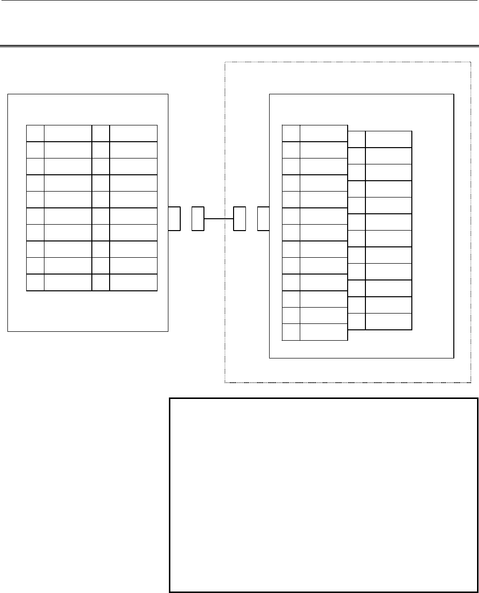
4.3 SERIAL PORT 1
1 RD 11 SD
2 0V 12 0V
3 DR 13 ER
4 0V 14 0V
5 CS 15 RS
6 (Reserve) 16 (Reserve)
7 CD 17 (Reserve)
8 (Reserve) 18 (Reserve)
9 RI 19 (+24V)
10 (+24V) 20 (Reserve)
( ): Used with FANUC I/O
device.
1 FG
2 SD
3 RD
4 RS
5 CS
6 DR
7 SG
8 CD
9
10
11
12
13
14
15
16
17
18
19
20 ER
21
22 RI
23
24
25
PANEL i
Relay connector
JD33
(PCR-EV20MDT)
(DSUB-25)
*(Reserve) Do not connect the pins.
NOTE
1 The figure shows a sample relay connector
interface. Design the cable to suit the interface of
the actual device to be connected.
2 The +24V pins of the interface for the PANEL i
shown above can be used only with the FANUC I/O
unit (such as FANUC CASSETTE and FANUC
Handy File). Do not use these pins for other
purposes. Also, do not attempt to simultaneously
connect two or more FANUC I/O units to one the
PANEL i.
If two or more I/O units are connected
simultaneously, the power supply capacity of the
+24 V pins may be exceeded.
Contents Summary of Panel i Connection And Maintenance Manual
- Page 1FANUC PANEL * CONNECTION AND MAINTENANCE MANUAL B-64223EN/01
- Page 2• No part of this manual may be reproduced in any form. • All specifications and designs are subject to change without notice. The export of this product is subject to the authorization of the government of the country from where the product is exported. In this manual we have tried as much as possi
- Page 3B-64223EN/01 DEFINITION OF WARNING, CAUTION, AND NOTE DEFINITION OF WARNING, CAUTION, AND NOTE This manual includes safety precautions for protecting the user and preventing damage to the machine. Precautions are classified into Warning and Caution according to their bearing on safety. Also, supplem
- Page 4
- Page 5B-64223EN/01 PREFACE PREFACE This manual explains information (electrical and structural specifications) required for connecting the FANUC PANEL i equipped with a 733-MHz Celeron, 866-MHz Pentium III, or 1.26-GHz Pentium III processor (called the PANEL i below) and the PANEL i for AUTOMOTIVE to a CN
- Page 6
- Page 7B-64223EN/01 TABLE OF CONTENTS TABLE OF CONTENTS DEFINITION OF WARNING, CAUTION, AND NOTE .................................s-1 PREFACE ....................................................................................................p-1 I. CONNECTION 1 TOTAL CONNECTION DIAGRAMS ...................
- Page 8TABLE OF CONTENTS B-64223EN/01 3.2.3 QWERTY MDI Used in Cases Other than Combination Subsection 3.2.2 ...........24 3.3 FRAME GROUNDING OF THE UNITS ....................................................... 25 3.3.1 PANEL i ..............................................................................
- Page 9B-64223EN/01 TABLE OF CONTENTS 6.3 BASIC UNIT 15.0” LCD TYPE FOR 150i/160i/180i/210i............................. 79 6.4 BASIC UNIT 10.4” LCD TYPE FOR 300i .................................................... 80 6.5 BASIC UNIT 12.1” LCD TYPE FOR 300i .................................................
- Page 10TABLE OF CONTENTS B-64223EN/01 4.2 CHANGING START SEQUENCES ........................................................... 109 4.3 EXPLANATION OF SCREENS ................................................................. 110 4.3.1 BOOT Screen .............................................................
- Page 11B-64223EN/01 TABLE OF CONTENTS 7 METHOD FOR CORRECTING POSITIONS ON THE TOUCH PANEL................................................................................................. 146 8 METHOD OF MOUNTING AND REMOVING THE 10.4-INCH PANEL i (FOR THE 300i) AND MDI UNIT ...............................
- Page 12
- Page 13I. CONNECTIO
- Page 14
- Page 15B-64223EN/01 CONNECTION 1.TOTAL CONNECTION DIAGRAMS 1 TOTAL CONNECTION DIAGRAMS -3-
- Page 161.TOTAL CONNECTION DIAGRAMS CONNECTION B-64223EN/01 1.1 PANEL i : Optical link Module & Cable : AMP(Dynamic) : AMP(mini-DIN6pins) CNC control unit : HONDA TSUSHIN (PCR 20pins) Master printed circuit board (300i) : HIROSE DENKI (Flat Cable34pins) HSSB(COP21) or HSSB option board : HIROSE DENKI (Flat
- Page 17B-64223EN/01 CONNECTION 1.TOTAL CONNECTION DIAGRAMS 1.2 PANEL i for AUTOMOTIVE CNC control unit Master printed circuit board (300i) HSSB(COP21) or HSSB interface board (150i/160i/180i/210i) I/O Link device I/O Link device HSSB(COP7) (master side) (slave side) PANEL i for AUTOMOTIVE HSSB JD1A JD1B (C
- Page 181.TOTAL CONNECTION DIAGRAMS CONNECTION B-64223EN/01 NOTE 1 Some peripheral devices are not suitable for being connected to the PANEL i for environmental durability reasons, and others are not suitable for use during machine operation. So, carefully read the operator's manuals of the peripheral devic
- Page 19B-64223EN/01 CONNECTION 2.SPECIFICATIONS 2 SPECIFICATIONS -7-
- Page 202.SPECIFICATIONS CONNECTION B-64223EN/01 2.1 HARDWARE SPECIFICATIONS 2.1.1 PANEL i Item Specification PC Unit (Basic Unit) Pentium III 1.26GHz or CPU Pentium III 866MHz or Celeron 733MHz Memory 512MB, 256M or 128MB 15.0” color TFT LCD (1024x768dots, 16M colors ) or Note) Windows XP for 150i/160i LCD
- Page 21B-64223EN/01 CONNECTION 2.SPECIFICATIONS 2.1.2 PANEL i for AUTOMOTIVE Item Specification PANEL i (Basic Unit) Pentium III 1.26GHz or CPU Pentium III 866MHz or Celeron 733MHz Memory 128MB,256M or 512MB LCD 15.0” color LCD (1024x768 dots, 16,000,000 colors) Display Option (1024x1024 dots. It is not po
- Page 222.SPECIFICATIONS CONNECTION B-64223EN/01 NOTE 1 Key arrangement is different from MDI. 2 In case of A08B-0084-B400, B401, B402, B403, B422, B423, A13B-0196-B400, B401, B402, B403, B422, B423, vertical soft keys signals go to only PC. In case of A08B-0084-B410, B411, A13B-0196-B410 and B411, vertical
- Page 23B-64223EN/01 CONNECTION 2.SPECIFICATIONS 2.2 ENVIRONMENT When the PANEL i is used, the following environmental conditions (as measured top of the unit inside the cabinet) must be ensured for the unit. Operating : +5 to +45°C Ambient temperature Non-operating : - 20 to +60°C Change in temperature Up
- Page 242.SPECIFICATIONS CONNECTION B-64223EN/01 2.2.2 Vibration The PANEL i and built-in hard disk drive may suffer resonance at certain frequencies. Careful checking is required on the PANEL i has been mounted on a machine. When a PCI extension board is used, the permissible vibration level may be lower t
- Page 25B-64223EN/01 CONNECTION 2.SPECIFICATIONS 2.3 POWER SPECIFICATION 2.3.1 Power Supply Requirement 2.3.1.1 Specification When the PANEL i is used, following power supply is required. Input Voltage +24VDC ± 10% Current capacity 10A or more over * If Handy File or other unit made by FANUC is connected to
- Page 262.SPECIFICATIONS CONNECTION B-64223EN/01 Example 1 CNC control unit Power supply DC24IN unit 1 I/O LINK Another I/O device DC24IN I/O LINK I/O Link PANEL i for Power-on/off switch AUTOMOTIVE UPS Power AC input supply DC24IN unit 2 I/O LINK RS232C Serial communication For a connection like this examp
- Page 27B-64223EN/01 CONNECTION 2.SPECIFICATIONS Example 2 CNC control unit DC24IN I/O I/O LINK Link Another I/O device DC24IN I/O LINK PANEL i Power-on/off switch for AUTOMOTIVE UPS Power AC input supply DC24IN unit I/O LINK RS232C Serial communication 2.3.2 Power Supply When a power supply which satisfies
- Page 282.SPECIFICATIONS CONNECTION B-64223EN/01 2.3.3 Power Consumption PANEL i Approx.64W (12.1” LCD type, 15.0” LCD type) Approx.58W (10.4” LCD type) PANEL i for AUTOMOTIVE Approx.60W Above operating includes the following devices. PANEL i, HDD Unit, FAN for HDD, Keyboard, and Mouse. Above operating does
- Page 29B-64223EN/01 CONNECTION 2.SPECIFICATIONS 2.4 SHUTDOWN OPERATION CAUTION Be sure to finish the OS and the applications through the proper operation of shutdown before turning the power off. Without the above-mentioned operation, there is no assurance of the following action. At worst, the hard disk d
- Page 303.MOUNTING CONNECTION B-64223EN/01 3 MOUNTING - 18 -
- Page 31B-64223EN/01 CONNECTION 3.MOUNTING 3.1 MOUNTING SPACE The following three spaces are required around the PANEL i and PANEL i for AUTOMOTIVE. A: Space for connecting cables. B: If PCI extension board exists, this space B is required for cable connection. The dimension X depends on cables connected to
- Page 323.MOUNTING CONNECTION B-64223EN/01 3.1.2 Installation Space of the 12.1" LCD Type Basic Unit NOTE Cable connecting area is necessary under this unit. - 20 -
- Page 33B-64223EN/01 CONNECTION 3.MOUNTING 3.1.3 Installation Space of the 15.0" LCD Type Basic Unit NOTE Cable connecting area is necessary under this unit. - 21 -
- Page 343.MOUNTING CONNECTION B-64223EN/01 3.1.4 Installation Space of the PANEL i for AUTOMOTIVE NOTE Cable connecting area is necessary under this unit. - 22 -
- Page 35B-64223EN/01 CONNECTION 3.MOUNTING 3.2 HDD UNIT The HDD unit is mounted on the backside of the MDI or the FA Full-Keyboard. (Except the PANEL i for AUTOMOTIVE) Obtain space for air circulation as shown in the figure below, and then obtain space for the cables used to connect the signals, power suppl
- Page 363.MOUNTING CONNECTION B-64223EN/01 3.2.2 When the QWERTY MDI and 10.4" LCD Type Basic Unit Are Used 3.2.3 QWERTY MDI Used in Cases Other than Combination Subsection 3.2.2 - 24 -
- Page 37B-64223EN/01 CONNECTION 3.MOUNTING 3.3 FRAME GROUNDING OF THE UNITS Connect every units (basic, FA full keyboard or MDI) to the grounding plate of the cabinet via grounding terminal. 3.3.1 PANEL i Grounding cable M4 stud 2mm2 or bigger 3.3.2 PANEL i for AUTOMOTIVE Grounding cable 2mm2 or bigger M4 s
- Page 383.MOUNTING CONNECTION B-64223EN/01 3.4 CABLE CLAMP AND SHIELD PROCESSING If a cable connected to the PANEL i requires shielding, clamp the cable as shown below. The clamp both supports and shields the cable. Use this clamp to ensure stable operation of the system. Partially peel out the sheath and e
- Page 39B-64223EN/01 CONNECTION 3.MOUNTING Prepare ground plate like the following figure. Ground terminal (grounded) Hole for securing metal fitting clamp Mount screw hole Fig. 3.4 (b) Ground plate For the ground plate, use a metal plate of 2 mm or thicker, which surface is plated with nickel. Ground plate
- Page 403.MOUNTING CONNECTION B-64223EN/01 (Reference) Outer drawings of metal fittings for clamp. Max. 55mm 28mm 6mm 17mm Fig. 3.4 (d) Outer drawings of metal fittings for clamp Ordering specification for metal fittings for clamp A02B-0124-K001 (8 pieces) - 28 -
- Page 41B-64223EN/01 CONNECTION 3.MOUNTING 3.5 DUSTPROOF MEASURES FOR CABINETS AND PENDANT BOXES The cabinet and pendant box that house a display and a operator's panel that are to be designed and manufactured by the machine tool builder are susceptible to dust, cutting debris, oil mist, etc. Note the follo
- Page 424.CONNECTION TO PERIPHERAL CONNECTION B-64223EN/01 4 CONNECTION TO PERIPHERAL - 30 -
- Page 43B-64223EN/01 CONNECTION 4.CONNECTION TO PERIPHERAL 4.1 CONNECTOR LOCATION 4.1.1 PANEL i CA78B View from the back side CA78A Power supply PCB Master printed circuit board PCI Back Panel PCB CD46L COP7 (150i/160i/180i/210i) COP21 (300i) CPD14 CPD11A CPD11B CD34 CPD11C CA81A CPE11C CA81B CD41L CD41M JD
- Page 444.CONNECTION TO PERIPHERAL CONNECTION B-64223EN/01 Power Supply PCB Connector Connector Function Reference Number Name CPD14 +24V INPUT Main Power Input Section 4.2 CPD11A FDD PWR FDD Power Output Section 4.9 CPD11B HDD PWR 1 HDD 1 Power Output Section 4.8 CPD11C HDD PWR 2 HDD 2 Power Output Section
- Page 45B-64223EN/01 CONNECTION 4.CONNECTION TO PERIPHERAL 4.1.2 PANEL i for AUTOMOTIVE View from CA78B the back side CA78A Power Supply PCB Floppy Disk Drive and Master PCB CD-ROM Drive Unit PCI Back Panel PCB CD46L COP7 (for 150i/160i/180i/210i) CD34 COP21 (for 300i) CA81A CPD14 CPD11A CPD11B CPD11C Hard
- Page 464.CONNECTION TO PERIPHERAL CONNECTION B-64223EN/01 Power Supply PCB Connector Connector Function Reference Number Name CPD14 +24V INPUT Main Power Input Section 4.2 CPD11A FDD PWR FDD Power Output - CPD11B HDD PWR 1 HDD Power Output - CPD11C HDD PWR 2 HDD Power Output - CPE11C HDD FAN FAN for HDD -
- Page 47B-64223EN/01 CONNECTION 4.CONNECTION TO PERIPHERAL 4.2 MAIN POWER SUPPLY INPUT PANEL i CPD14 A1 +24V B1 +24V A2 0V B2 0V A3 B3 Cable connection A1 +24V ● +24V A2 0V ● 0V B1 +24V B2 0V Cable conductor Use wire of AWG#16 (1.3mm2)or thicker. Recommended contact and housing for cable Contact Housing Man
- Page 484.CONNECTION TO PERIPHERAL CONNECTION B-64223EN/01 4.3 SERIAL PORT 1 PANEL i Relay connector JD33 (PCR-EV20MDT) (DSUB-25) 1 RD 11 SD 1 FG 14 2 0V 12 0V 2 SD 15 3 DR 13 ER 3 RD 16 4 0V 14 0V 4 RS 17 5 CS 15 RS 5 CS 18 6 (Reserve) 16 (Reserve) 6 DR 19 7 CD 17 (Reserve) 7 SG 20 ER 8 (Reserve) 18 (Reser
- Page 49B-64223EN/01 CONNECTION 4.CONNECTION TO PERIPHERAL Cable connection JD33 Relay connector DSUB-25 1 3 RD RD 2 0V 3 6 DR DR 4 0V 5 5 CS CS 6 7 8 CD CD 8 9 22 RI RI 11 2 SD SD 12 0V 13 20 ER ER 14 7 0V SG 15 4 RS RS 16 17 18 10 25 +24V +24V 19 1 +24V FG 20 GND Shield Recommended cable conductor A66L-00
- Page 504.CONNECTION TO PERIPHERAL CONNECTION B-64223EN/01 Recommended punch panel A02B-0236-C191(1m), A02B-0236-C192(2m), A02B-0236-C193(5m) CAUTION CNC punch panels (A02B-0120-C191 to A02B-0120-C193, etc.) other than the panels indicated above cannot be used with this interface. Use of such an incorrect p
- Page 51B-64223EN/01 CONNECTION 4.CONNECTION TO PERIPHERAL 4.4 SERIAL PORT 2 PANEL i Relay connector JD46 (DSUB-9) (PCR-EV20MDT) 1 RD 11 SD 1 CD 6 DR 2 0V 12 USB1_0V 2 RD 7 RS 3 DR 13 ER 3 SD 8 CS 4 0V 14 USB2_0V 4 ER 9 RI 5 CS 15 RS 5 SG 6 USB1+ 16 USB2+ 7 CD 17 USB2- 8 USB1- 18 USB2_5V 9 RI 19 (+24V) 10 (
- Page 524.CONNECTION TO PERIPHERAL CONNECTION B-64223EN/01 NOTE 1 The figure shows a sample relay connector interface and USB. Design the cable to suit the interface of the actual device to be connected. 2 The +24V pins of the interface for PANEL i shown above can be used only with the FANUC I/O unit (such
- Page 53B-64223EN/01 CONNECTION 4.CONNECTION TO PERIPHERAL Cable connection - When an RS-232C connector is used JD46 Relay connector DSUB-9 1 2 RD RD 2 0V 3 6 DR DR 4 5 0V SG 5 8 CS CS 7 1 CD CD 9 9 RI RI 10 +24V 11 3 SD SD 13 4 ER ER 15 7 RS RS 19 +24V Shield - 41 -
- Page 544.CONNECTION TO PERIPHERAL CONNECTION B-64223EN/01 - When a USB port is used JD46 Punch panel for USB port 20 1 USB1_5V USB1_5V 8 2 USB1- USB1- 6 3 USB1+ USB1+ 12 4 USB1_0V USB1_0V Shield JD46 Punch panel for USB port 18 1 USB2_5V USB2_5V 17 2 USB2- USB2- 16 3 USB2+ USB2+ 14 4 USB2_0V USB2_0V Shield
- Page 55B-64223EN/01 CONNECTION 4.CONNECTION TO PERIPHERAL - When an RS-232C connector and USB port are used JD46 Punch panel side JD46 1 1 RD RD 2 2 0V 0V 3 3 DR DR 5 5 CS CS 7 7 CD CD 9 9 RI RI 4 4 0V 0V 11 11 SD SD 13 13 ER ER 15 15 RS RS 20 20 USB1_5V USB1_5V 8 8 USB1- USB1- 6 6 USB1+ USB1+ 12 12 USB1_0
- Page 564.CONNECTION TO PERIPHERAL CONNECTION B-64223EN/01 Recommended cable specifications For RS-232C signals : A66L-0001-0284#10P (0.08 mm2, 10 pairs) For USB ports : Use dedicated cables. For RS-232C signals and USB ports : A66L-0001-0285#25P AWG28 25 pairs Recommended punch panel For RS-232C signals :
- Page 57B-64223EN/01 CONNECTION 4.CONNECTION TO PERIPHERAL 4.5 PARALLEL PORT PANEL i (Example) Printer JD9 (PCR-EV20MDT) 1 STD0 11 *STB 1 *STB 19 0V 2 STD1 12 0V 2 STD0 20 0V 3 STD2 13 *AFD 3 STD1 21 0V 4 STD3 14 0V 4 STD2 22 0V 5 STD4 15 *INIT 5 STD3 23 0V 6 STD5 16 0V 6 STD4 24 0V 7 STD6 17 *SLIN 7 STD5 2
- Page 584.CONNECTION TO PERIPHERAL CONNECTION B-64223EN/01 Cable connection JD9 (Example) Printer 1 2 STD0 STD0 12 16 0V 0V 2 3 STD1 STD1 19 0V 3 4 STD2 STD2 20 0V 4 5 STD3 STD3 21 0V 5 6 STD4 STD4 22 0V 6 7 STD5 STD5 23 0V 7 8 STD6 STD6 14 24 0V 0V 8 9 STD7 STD7 25 0V 9 12 PE PE 26 0V 10 13 SLCT SLCT 27 0V
- Page 59B-64223EN/01 CONNECTION 4.CONNECTION TO PERIPHERAL RECOMMENDED CABLE MATERIAL SPEC. A66L-0001-0285#25P: AWG28 25 pairs RECOMMENDED CONNECTOR FOR CABLE and HOUSING (JD9 side) Connector Housing Manufacture FI40B-20S FI-20-CV5 Hirose Electric - 47 -
- Page 604.CONNECTION TO PERIPHERAL CONNECTION B-64223EN/01 4.6 HIGH SPEED SERIAL BUS (HSSB) HSSB interface board (CNC side) PANEL i PANEL i for AUTOMOTIVE COP7 (for 150i/160i/180i/210i) COP7 (for 150i/160i/180i/210i) Optical fiber cable COP21 (for 300i) COP21 (for 300i) RECOMMENDED CABLE(Optical Fiber Cable
- Page 61B-64223EN/01 CONNECTION 4.CONNECTION TO PERIPHERAL Low-loss optical junction adapter A63L-0020-0004 For HSSB, optical fiber cables, and relay adapters, also refer to the relevant CNC connection manual and the following technical report. Name Specification number FANUC High-speed serial Bus Type 2 A-
- Page 624.CONNECTION TO PERIPHERAL CONNECTION B-64223EN/01 4.7 KEYBOARD AND MOUSE PANEL i Full keyboard (commercial model) CD32L (mini DIN6) 6 5 KEYCLK 4 +5V 3 0V KB 2 1 KEYDATA Alternatively, FA full keyboard Mouse (commercial model) 6 5 MSCLK MS 4 +5V 3 0V 2 1 MSDATA Mouse (commercial model) NOTE 1 Commer
- Page 63B-64223EN/01 CONNECTION 4.CONNECTION TO PERIPHERAL Recommended full keyboard A86L-0001-0210 : 101 type (commercial model) Only for application development or maintenance A86L-0001-0211 : 106 type (commercial model) Only for application development or maintenance A02B-0236-C131#JC : FA Full Keyboard
- Page 644.CONNECTION TO PERIPHERAL CONNECTION B-64223EN/01 4.8 HARD DISK UNIT Cable Connection Connect HDD signal cable to CA81A. Connect HDD power cable to CPD11B. Connect FAN cable to CPE11C. Connect the above cables. These cables are factory-connected to the hard disk unit. Cable Length HDD power cable :
- Page 65B-64223EN/01 CONNECTION 4.CONNECTION TO PERIPHERAL 4.9 FLOPPY DISK DRIVE Recommended floppy disk drive Drive unit (separate type): A08B-0084-K001 Panel-mounted type: A02B-0207-C009 When a conventional FDD unit is used, a setting on the master printed circuit board must be changed. (Make TM1 open.) C
- Page 664.CONNECTION TO PERIPHERAL CONNECTION B-64223EN/01 4.10 USB USB port 1 PANEL i for 300i JD41L 1 USB1_5V 2 USB1- 3 USB1+ 12 34 4 USB1_0V USB port 2 JD41M 1 USB2_5V 2 USB2- 3 USB2+ 12 34 USB port 3 4 USB2_0V PANEL i for AUTOMOTIVE USB port 3 CD46L 1 USB2_5V 2 USB2- 3 USB2+ 12 34 4 USB2_0V USB port 1 i
- Page 67B-64223EN/01 CONNECTION 4.CONNECTION TO PERIPHERAL NOTE 1 Commercially available USB devices are prone to compatibility problems with personal computers to some degree. It is not guaranteed that every commercially available USB device can operate properly with personal computers. Machine tool builde
- Page 684.CONNECTION TO PERIPHERAL CONNECTION B-64223EN/01 4.11 ETHERNET CAUTION Before attaching or detaching cables, turn off the power to the PANEL i, and ensure that the power is off. Please inquire of each manufacturer about the construction of network or the condition of using the equipment except the
- Page 69B-64223EN/01 CONNECTION 4.CONNECTION TO PERIPHERAL Leading out the Ethernet cable The Ethernet cable must be fastened by a cable clamp to prevent tension being applied to the modular connector (RJ-45) that connects the cable to the control unit even if the Ethernet cable is pulled directly. This cla
- Page 704.CONNECTION TO PERIPHERAL CONNECTION B-64223EN/01 4.11.2 Twisted-Pair Cable Specification Cable Connection The cable used for connection between the 10BASE-T/100BASE-TX interface CD38U and the hub is connected as follows: CD38U HUB 1 TX+ 1 TX+ RJ-45 2 TX- 2 TX- modular connector 3 RX+ 3 RX+ 4 4 5 5
- Page 71B-64223EN/01 CONNECTION 4.CONNECTION TO PERIPHERAL Inquiries Manufacturer Contact address Furukawa Electric Co., Ltd. 2-6-1 Marunouchi, Chiyoda-ku. Tokyo 100-8322 Sales Headquarters TEL: 03-3286-3126 FAX: 03-3286-3979 Nissei Electric Co., Ltd. 3F MU Bldg., 1-9-1 Minami-narise, Machida City, Machida
- Page 724.CONNECTION TO PERIPHERAL CONNECTION B-64223EN/01 About cable assemblies Oki Electric Cable Co., Ltd. can offer a cable assembly that uses the TM21CP-88P(03) connector made by Hirose Electric Co., Ltd. To get this cable assembly, negotiate directly with the manufacturer on its specifications (cable
- Page 73B-64223EN/01 CONNECTION 4.CONNECTION TO PERIPHERAL 4.11.3 Electrical Noise Countermeasures Separating signal lines Ethernet cable wires belong to group C. See descriptions elsewhere for explanations about how to separate them from wires in group A or B. Group Signal line Action A Primary AC power li
- Page 744.CONNECTION TO PERIPHERAL CONNECTION B-64223EN/01 4.11.4 Grounding the Network Even if the grounding condition on the machine side is satisfied, the communication line can pick up noise from the machine, depending on the machine installation condition and environment, thus resulting in a communicat
- Page 75B-64223EN/01 CONNECTION 4.CONNECTION TO PERIPHERAL 4.12 VIDEO PORT PANEL i (Example) Monitor JA63 (PCR-EV20MDT) (Dsub-15) 1 RED 11 (PU_1) 6 0V 1 RED 11 (SENCE) 2 0V 12 VS 7 0V 2 GREEN 12 (DDA) 3 GREEN 13 0V 8 0V 3 BLUE 13 HS 4 0V 14 0V 9 (+5V) 4 (PU_1) 14 VS 5 BLUE 15 (+5V) 10 0V 5 0V 15 (DCK) 6 0V
- Page 764.CONNECTION TO PERIPHERAL CONNECTION B-64223EN/01 Notes (1) Use of this port does not require any special setting on the PANEL i. (2) When an external monitor is connected to this port directly, the maximum cable length is 2 m if the above recommended cable is used. To extend the cable beyond the m
- Page 77B-64223EN/01 CONNECTION 4.CONNECTION TO PERIPHERAL 4.13 MDI (FOR 300i) PANEL i MDI JA61 CK1 (PCR-EV20MDT) (PCR-E20MDK-SL-A) 1 *KEY00 11 *KEY01 1 *KEY00 11 *KEY01 2 *KEY02 12 *KEY03 2 *KEY02 12 *KEY03 3 *KEY04 13 *KEY05 3 *KEY04 13 *KEY05 4 *KEY06 14 *KEY07 4 *KEY06 14 *KEY07 5 *COM00 15 *COM01 5 *CO
- Page 784.CONNECTION TO PERIPHERAL CONNECTION B-64223EN/01 Cable connection JD61 (Example) MDI 1 1 *KEY00 *KEY00 2 2 *KEY02 *KEY02 3 3 *KEY04 *KEY04 4 4 *KEY06 *KEY06 5 5 *COM00 *COM00 6 6 *COM02 *COM02 7 7 *COM04 *COM04 8 8 *COM06 *COM06 9 9 *COM08 *COM08 10 10 *COM10 *COM10 11 11 *KEY01 *KEY01 12 12 *KEY0
- Page 79B-64223EN/01 CONNECTION 4.CONNECTION TO PERIPHERAL MDI connection to CNC In case of 300i, the soft key is connected internally and MDI signals are connected to CNC via HSSB. 300i 150i/160i/180i/210i Soft key Soft key Stand-alone type Stand-alone type 300i 150i/160i/180i/210i MDI cable MDI MDI HSSB o
- Page 804.CONNECTION TO PERIPHERAL CONNECTION B-64223EN/01 4.14 CONVERSION OF VERTICAL SOFT KEYS AND I/O LINK Vertical soft keys can be read from CNC directly via I/O Link if the PANEL i for AUTOMOTIVE have I/O Link conversion function. It depends on the specification of the unit the way of connection to ve
- Page 81B-64223EN/01 CONNECTION 4.CONNECTION TO PERIPHERAL c. With I/O Link conversion function (A08B-0084-B412~3,-B432,-B433, A13B-0196-B412~3,-B432,-B433) Vertical soft keys are usable both in CNC and in PC. PANEL i for AUTOMOTIVE Vertical soft keys PC function I/O Link conversion CNC Connection to CNC or
- Page 824.CONNECTION TO PERIPHERAL CONNECTION B-64223EN/01 JD1A JD1B (PCR-E20MDA) (PCR-E20MDA) 1 SIN 11 0V 1 SIN 11 0V 2 *SIN 12 0V 2 *SIN 12 0V 3 SOUT 13 0V 3 SOUT 13 0V 4 *SOUT 14 0V 4 *SOUT 14 0V 5 (Reserve) 15 (Reserve) 5 (Reserve) 15 (Reserve) 6 (Reserve) 16 (Reserve) 6 (Reserve) 16 (Reserve) 7 (Reserv
- Page 83B-64223EN/01 CONNECTION 4.CONNECTION TO PERIPHERAL Recommended cable material A66L-0001-0284#10P: 0.08mm2 × 10 pairs Recommended connector and housing for cable Connector Housing Manufacture PCR-E20FA PCR-V20LA/PCS-E20LA Honda Tsushin Kogyo FI30-20S FI-20-CV2/FI-20-CV7 Hirose Electric FCN-247J020-G/
- Page 844.CONNECTION TO PERIPHERAL CONNECTION B-64223EN/01 4.15 PCMCIA CARD Front of PANEL i Door PCMCIA card slot Back side PCMCIA card (Type I, Type II) NOTE 1 Only Type I or Type II PCMCIA card is usable. The following card cannot be used. - Card-bus card - Dual mode card (Card-bus mode/PCMCIA mode) with
- Page 85B-64223EN/01 CONNECTION 5.METHOD OF MOUNTING PCI EXTENSION BOARD 5 METHOD OF MOUNTING PCI EXTENSION BOARD - 73 -
- Page 865.METHOD OF MOUNTING PCI EXTENSION BOARD CONNECTION B-64223EN/01 5.1 USABLE BOARD The size of usable board on the PANEL i is defined as below figure, and one or two boards can be mounting on the PANEL i. Parts height of back side : up to 3mm Fix by screw Parts height of front side : up to 13mm Up to
- Page 87B-64223EN/01 CONNECTION 5.METHOD OF MOUNTING PCI EXTENSION BOARD 5.2 METHOD OF MOUNTING PCI EXTENSION BOARD (1) Release vibration-proof fittings 1, 2 by loosening the screw at point (B). (2) Push the board fully into the PCI connector. (3) Tighten the screw at point (A). (4) Press down vibration-pro
- Page 886.OUTLINE DRAWINGS CONNECTION B-64223EN/01 6 OUTLINE DRAWINGS - 76 -
- Page 89B-64223EN/01 CONNECTION 6.OUTLINE DRAWINGS 6.1 BASIC UNIT 10.4” LCD TYPE FOR 150i/160i/180i/210i - 77 -
- Page 906.OUTLINE DRAWINGS CONNECTION B-64223EN/01 6.2 BASIC UNIT 12.1” LCD TYPE FOR 150i/160i/180i/210i - 78 -
- Page 91B-64223EN/01 CONNECTION 6.OUTLINE DRAWINGS 6.3 BASIC UNIT 15.0” LCD TYPE FOR 150i/160i/180i/210i - 79 -
- Page 926.OUTLINE DRAWINGS CONNECTION B-64223EN/01 6.4 BASIC UNIT 10.4” LCD TYPE FOR 300i Upper view Front view Side view PCI card cable connection area Cable connection area Frame ground Drawing of the lower-right corner on the rear Panel cut drawing (Screw the unit from the outside of the cabinet then att
- Page 93B-64223EN/01 CONNECTION 6.OUTLINE DRAWINGS 6.5 BASIC UNIT 12.1” LCD TYPE FOR 300i 6-M4 stud - 81 -
- Page 946.OUTLINE DRAWINGS CONNECTION B-64223EN/01 6.6 BASIC UNIT 15.0” LCD TYPE FOR 300i Upper view 8-M4 stud 400 Side view Front view Cable connection area PCI card cable connection area Frame ground Drawing of the lower-right corner on the rear Weight: 5.1 kg Panel cut drawing (Unit: mm) Area for packing
- Page 95B-64223EN/01 CONNECTION 6.OUTLINE DRAWINGS 6.7 BASIC UNIT (PANEL i for AUTOMOTIVE) 125 12.65 Upper View (Without FDD&CD-ROM Drive Unit) This size is 20mm at the screw of the doors of PCMCIA slot and USB interface. 160 Upper View (With FDD&CD-ROM Drive Unit) 482.6 Screw lock for door 354.8 Screw lock
- Page 966.OUTLINE DRAWINGS CONNECTION B-64223EN/01 7.5 97.9 134.6 134.6 97.9 7.5 6.8 29.6 101.6 76.2 101.6 6.8 29.6 14-M4 Rear view 473 97.9 134.6 134.6 97.9 29.6 101.6 325 450 76.2 346.6 101.6 6.8 7.5 29.6 14-Φ5 Panel cutting Area for packing attachment (Mount the unit from the outside of the cabinet and s
- Page 97B-64223EN/01 CONNECTION 6.OUTLINE DRAWINGS Details of the vertical key sheet Details of the horizontal key sheet - 85 -
- Page 986.OUTLINE DRAWINGS CONNECTION B-64223EN/01 6.8 HARD DISK DRIVE UNIT A (FOR 150i/160i/180i/210i AND 300i) A08B-0084-H100 44.6 4-φ6 37.6 6 66 136 42 40 6 28 25 83 39 Weight: 1.1 kg (Unit: mm) - 86 -
- Page 99B-64223EN/01 CONNECTION 6.OUTLINE DRAWINGS 6.9 HARD DISK DRIVE UNIT B, C (FOR 300i) A08B-0084-H130 44.6 9.2 163 29 39.2 6 180 6 8.3 35.35 121.3 40 119.7 35.35 8.3 6 4-φ6 Weight: 1.1 kg (Unit: mm) A08B-0084-H131 4-φ6 8 8 19.2 28.4 101.4 25.8 67 35.3 121.3 40 35.4 Weight: 1.2 kg (Unit: mm) - 87 -
- Page 1006.OUTLINE DRAWINGS CONNECTION B-64223EN/01 6.10 FLOPPY DISK DRIVE A08B-0084-K001 The tolerance shall be ±1.0 unless otherwise specified. (Unit: mm) Fig. 6.9(a) External View Weight: 0.4Kg Fig. 6.9(b) Installation Orientations Unit: mm - 88 -
- Page 101B-64223EN/01 CONNECTION 6.OUTLINE DRAWINGS A02B-0207-C009 5 4-φ3.6 J2 FDD 150 140 ACRYLIC 104 J1 WINDOW 145 5 70 5 5 80 Front View Side view 4-M3 Weight: 0.8Kg Unit: mm 134 140 64 (HOLE) 70 Panel Cutting - 89 -
- Page 1026.OUTLINE DRAWINGS CONNECTION B-64223EN/01 6.11 CD-ROM DRIVE A08B-0084-K010 148 42.3 136 max. When the tray is open 5 52.4 79.2 202 11.8 10 139.7 41.3 146 Weight: 1.0kg 12-M3 Depth: 5 max. Unit: mm - 90 -
- Page 103II. MAINTENANC
- Page 104
- Page 105B-64223EN/01 MAINTENANCE 1.SYSTEM BLOCK DIAGRAM 1 USB SYSTEM BLOCK DIAGRAM Keyboard and Controller CP1 In case of Touch Panel Touch Panel Controller PCB CN4 CD37 PCMCIA I/F PCMCIA Clock CA82 Controller Generator JA63 CRT USB I/F CD46L CPU FDD SIGNAL CD34 Memory DIMM CD32L KEYBOARD LCD CNA1 Signal Ch
- Page 1061.SYSTEM BLOCK DIAGRAM MAINTENANCE B-64223EN/01 NOTE 1 Detail of Inverter In case of 10.4” Main Board (A20B-8100-093X) 10.4”LCD Inverter Unit CN2 CN1 CPC11 In case of 12.1”LCD 12.1”LCD Inverter Unit CP1 CP2 CP31 In case of 15.0”LCD 15.0”LCD Inverter Unit CN02 CN01 CN03 CN04 CN05 - 94 -
- Page 107B-64223EN/01 MAINTENANCE 2.LIST OF THE PCBS, UNITS, MAINTENANCE SUPPLIES AND TOOLS 2 LIST OF THE PCBS, UNITS, MAINTENANCE SUPPLIES AND TOOLS - 95 -
- Page 1082.LIST OF THE PCBS, UNITS, MAINTENANCE SUPPLIES AND TOOLS MAINTENANCE B-64223EN/01 2.1 LIST OF PCBS 2.1.1 Main PCB Specification of CNC Unit LCD type Applied Basic Unit Main PCB A08B-0084-B001~4, -B011~4 10.4”/12.1” A20B-8100-0930 A13B-0196-B001~4, -B011~4 160i PANEL i A08B-0084-B021, -B023 /180i 15
- Page 109B-64223EN/01 MAINTENANCE 2.LIST OF THE PCBS, UNITS, MAINTENANCE SUPPLIES AND TOOLS 2.1.4 Touchpanel PCB Specification of CNC Unit Applied Basic Unit Touch panel PCB A08B-0084-B003~4 A13B-0196-B003~4 160i PANEL i A20B-8001-0620 A08B-0084-B013~4 A13B-0196-B013~4 /180i A08B-0084-B023 A13B-0196-B023 /21
- Page 1102.LIST OF THE PCBS, UNITS, MAINTENANCE SUPPLIES AND TOOLS MAINTENANCE B-64223EN/01 2.2 LIST OF MAINTENANCE UNITS 2.2.1 Drive Unit Specification of Supplied Order Name Unit Remark Maintenance Unit Specification PANEL i for 160i /180i A08B-0082-C102#D A08B-0084-H100 /210i PANEL i for Automotive A08B-0
- Page 111B-64223EN/01 MAINTENANCE 2.LIST OF THE PCBS, UNITS, MAINTENANCE SUPPLIES AND TOOLS 2.2.2 Base Unit LCD I/O Link Soft Touch Specification of Unit CNC Applied Unit type Adapter key panel Base Unit *1 X X A08B-0084-D001 A08B-0084-B001 A13B-0196-B001 10.4” O X A08B-0084-D002 A08B-0084-B002 A13B-0196-B00
- Page 1122.LIST OF THE PCBS, UNITS, MAINTENANCE SUPPLIES AND TOOLS MAINTENANCE B-64223EN/01 2.3 LIST OF CPU AND MEMORY Specification of Applied Order Name Maintenance Parts Specification Celeron 733MHz A08B-0084-C210 A08B-0084-H010 CPU Pentium III 866MHz A08B-0084-C220 A08B-0084-H020 Pentium III 1260MHz A08B
- Page 113B-64223EN/01 MAINTENANCE 3.CONFIGURATION AND SETTING OF THE PCB 3 CONFIGURATION AND SETTING OF THE PCB - 101 -
- Page 1143.CONFIGURATION AND SETTING OF THE PCB MAINTENANCE B-64223EN/01 3.1 PARTS LAYOUT CA85 VR1 CPU CA79 Socket Chipset1 PCMCIA (GMCH) Controller DIMM Socket (SD-RAM) JA64 CA82 CK22 CPD12 CK23 BIOS Chipset2 Chipset3 (ICH2) SIO CD46L ROM CD37 CPC11 CD41M CD41L JD33 JD46 JD9 JA61 JA63 CD34 CD32U (Upper) CA8
- Page 115B-64223EN/01 MAINTENANCE 3.CONFIGURATION AND SETTING OF THE PCB CA78B PCI Slot 2 LED2A LED1A CA78A PCI Slot 1 HSSB PCI I/F COP21M Controller JA64 PC Extension I/F Backplane for 300i (A20B-8002-0330) Parts Layout CPD14 CN3 CPE11B CPE11A CPD11A CPD11B CPD11C CPE11C FUSE CPD12 Power PCB (A20B-2100-0920
- Page 1163.CONFIGURATION AND SETTING OF THE PCB MAINTENANCE B-64223EN/01 3.2 ADJUSTMENT 3.2.1 Setting of Short Plug Name Meaning Settings Remark Setting for designated TM1 Short FDD. TM1 FDD Mode Default on manufacture. Setting for old FANUC TM1 Open FDD. PWB revision is 03 or less. Default on manufacture. T
- Page 117B-64223EN/01 MAINTENANCE 3.CONFIGURATION AND SETTING OF THE PCB 3.3 LED DISPLAY 3.3.1 LED on Main Board GR5 GR4 GR6 RE2 RE3 RE1 CD41M CD32 GR3 GR2 GR1 Name1 Name2 Color Status RE1 TRM Red Thermal Alarm. Thermal is not in regulated range. RE2 BAT Red Battery alarm. The battery on PANEL i is exhausted
- Page 1184.MAINTENANCE OF OPEN CNC (BOOT-UP AND IPL) MAINTENANCE B-64223EN/01 4 MAINTENANCE OF OPEN CNC (BOOT-UP AND IPL) - 106 -
- Page 119B-64223EN/01 MAINTENANCE 4.MAINTENANCE OF OPEN CNC (BOOT-UP AND IPL) 4.1 OVERVIEW Ncboot32.exe can be used for the maintenance of the CNC. Unless otherwise specified, the following examples assume the use of Ncboot32.exe of the Windows 2000/XP version. Ncboot32.exe provides the following functions:
- Page 1204.MAINTENANCE OF OPEN CNC (BOOT-UP AND IPL) MAINTENANCE B-64223EN/01 System tray Right-click the icon in the system tray, and the popup menu, shown below, appears at the lower left corner of the screen. Selecting [Open] causes the status screen to open. Selecting [About] causes the version informati
- Page 121B-64223EN/01 MAINTENANCE 4.MAINTENANCE OF OPEN CNC (BOOT-UP AND IPL) 4.2 CHANGING START SEQUENCES Placing the rotary switch on the HSSB board in the option slot to the 0 position (for the 160i/180i/210i) or the rotary switch on the CNC main board to the F position (for the 300i) allows you to perfor
- Page 1224.MAINTENANCE OF OPEN CNC (BOOT-UP AND IPL) MAINTENANCE B-64223EN/01 4.3 EXPLANATION OF SCREENS NOTE To open each screen of Ncboot32.exe, you are recommended to use either the mouse or touch panel. 4.3.1 BOOT Screen The area where the file is to be placed can be changed by using the [Setting...] but
- Page 123B-64223EN/01 MAINTENANCE 4.MAINTENANCE OF OPEN CNC (BOOT-UP AND IPL) 4.3.1.1 System data manipulation The following screen is used for manipulating system data (including control software and ladder programs) on the NC. [Load...] opens the file selection screen. Specify a file to be loaded. [Save] s
- Page 1244.MAINTENANCE OF OPEN CNC (BOOT-UP AND IPL) MAINTENANCE B-64223EN/01 4.3.1.2 SRAM operation This screen is used to store and restore NC SRAM data. [Backup] stores SRAM data, and [Restore] restores SRAM data. In the center of the screen, the progress status is displayed. As with the NC, the backup fi
- Page 125B-64223EN/01 MAINTENANCE 4.MAINTENANCE OF OPEN CNC (BOOT-UP AND IPL) 4.3.1.3 File operation The following screen is used for operating files on a memory card in the CNC or in a folder of the PANEL i. [Delete] deletes a selected file. [Format] formats the memory card. This button is valid when the me
- Page 1264.MAINTENANCE OF OPEN CNC (BOOT-UP AND IPL) MAINTENANCE B-64223EN/01 4.3.2 IPL Screen NOTE The contents of the IPL screen vary depending on the CNC model. Follow the instructions displayed in the menu. - 114 -
- Page 127B-64223EN/01 MAINTENANCE 4.MAINTENANCE OF OPEN CNC (BOOT-UP AND IPL) 4.4 OTHER SCREENS 4.4.1 CNC Alarm Screen This screen appears when a system alarm is issued in the CNC. (The above screen is an example. The displayed information varies depending on the system alarm issued in the CNC.) - 115 -
- Page 1284.MAINTENANCE OF OPEN CNC (BOOT-UP AND IPL) MAINTENANCE B-64223EN/01 4.4.2 Status Screen To open the status screen, double-click the icon in the system tray. Alternatively, in the menu popped up by right-clicking, click OPEN. Node: Node number Name: Node name. (Define the node name in advance by usi
- Page 129B-64223EN/01 MAINTENANCE 4.MAINTENANCE OF OPEN CNC (BOOT-UP AND IPL) 4.4.3 Option Setting Screen On the option setting screen, application programs can be registered. Any programs for use with FOCAS2 will not run unless they are started after FOCAS2 starts. By registering these programs in Ncboot32.
- Page 1305.BIOS SETUP MAINTENANCE B-64223EN/01 5 BIOS SETUP - 118 -
- Page 131B-64223EN/01 MAINTENANCE 5.BIOS SETUP 5.1 WHAT IS ‘BIOS SET-UP’ “BIOS Set-up” is a program to set up BIOS settings, and operating environment for the PANEL i is defined by these BIOS settings. It is unnecessary to run the set-up program normally because default BIOS settings are set at shipping. Use
- Page 1325.BIOS SETUP MAINTENANCE B-64223EN/01 5.3 HOW TO BEGIN THE ‘BIOS SET-UP’ 1 Finish working and store the data. 2 Turn off and connect a full-keyboard, and turn on again. 3 BIOS set-up will run with pressing “F2” key while “Press
to enter SETUP.” is displayed. PhoenixBIOS 4.0 Release 6.0 Copyrigh - Page 133B-64223EN/01 MAINTENANCE 5.BIOS SETUP 5.4 HOW TO END THE ‘BIOS SET-UP’ Changed settings become effective after saving settings and restarting the system. Select either one of the following methods for saving and restarting. (Method 1) : Set Exit mode by pressing ESC key or selecting “EXIT” item. The
- Page 1345.BIOS SETUP MAINTENANCE B-64223EN/01 5.5 BIOS DIAGNOSIS MESSAGE After turning on the system POST (Power On Self Test) is executed. Diagnosis messages in the following table may be displayed. Marks in item “To be solved” represent as bellow. A: Something of hardware may be failure. Solve these troub
- Page 135B-64223EN/01 MAINTENANCE 6.MAINTENANCE SUPPLIES 6 MAINTENANCE SUPPLIES - 123 -
- Page 1366.MAINTENANCE SUPPLIES MAINTENANCE B-64223EN/01 6.1 METHOD OF EXCHANGING A BATTERY CAUTION The time from disconnecting the cable of old battery to connecting the cable of new battery should be shorter than 5 minutes. BIOS settings will be not erased when bellow procedures are done correctly. But if
- Page 137B-64223EN/01 MAINTENANCE 6.MAINTENANCE SUPPLIES Battery Connector (BAT1) Battery A02B-0200-K102 Fig. 6.1 Exchanging a battery - 125 -
- Page 1386.MAINTENANCE SUPPLIES MAINTENANCE B-64223EN/01 6.2 METHOD OF REMOVING CASE COVER erased because battery cable is pulled out. In that case “251: System CMOS checksum bad – Default configuration used.” & “Press
to enter SETUP” are displayed after next turning on. Therefore in case of usage with - Page 139B-64223EN/01 MAINTENANCE 6.MAINTENANCE SUPPLIES (3) Detaching the PCI card <2> <1> <1> Remove the PCI holding part. <2> Remove the screw, and pull out the PCI card. (4) Removing screws from the case a b d c e <1> For units other than the 15” LCD, remove the screw (a) from the upper right section of
- Page 1406.MAINTENANCE SUPPLIES MAINTENANCE B-64223EN/01 (5) Checking the shape of the PCI holding plate at the bottom of the unit <1> Old type <2> New type <1> If the holding plate is an old type, remove it first. <2> If the holding plate is a new type, remove the screw indicated with an arrow, and loosen t
- Page 141B-64223EN/01 MAINTENANCE 6.MAINTENANCE SUPPLIES (8) Removing the cover - 129 -
- Page 1426.MAINTENANCE SUPPLIES MAINTENANCE B-64223EN/01 6.3 MOUNTING THE CASE COVER (1) Position the upper side of the cover in the right place, and lower it. Series 300i : Be careful. They are tight. Be careful not to have the case cover caught on Make sure that the power supply PCB and the DIMM latch. bac
- Page 143B-64223EN/01 MAINTENANCE 6.MAINTENANCE SUPPLIES (4) Attach the cable connector. 40-mm-square fan 60-mm-square fan Battery (5) Attach the LCD cable, and mount the metal fitting and cable clamp. (For the 15.0” LCD unit only) - 131 -
- Page 1446.MAINTENANCE SUPPLIES MAINTENANCE B-64223EN/01 6.4 METHOD OF EXCHANGING FUSE CAUTION Investigate the cause that fuse is blown out at first, then remove it. Fuse is blown out when power lines are shorted in PANEL i. If the fuse is blown out, check bellow points. - Any conductor is shorted to the mai
- Page 145B-64223EN/01 MAINTENANCE 6.MAINTENANCE SUPPLIES 6.5 METHOD OF EXCHANGING FAN 6.5.1 Method of Exchange Fan of the PANEL i (1) Make sure that PANEL i is turned off. (2) Prepare a new FAN . (3) Pull out the connector of fan power. This connector has a latch, therefore release the latch and pull out it
- Page 1466.MAINTENANCE SUPPLIES MAINTENANCE B-64223EN/01 6.5.2 Method of Exchanging Fan for the HDD Unit (1) Make sure that PANEL i is turned off. (2) Prepare a new fan. (3) Disconnect the fan connector from CPE11C. The connector has a latch, therefore disconnect it while raising upward it a little. (4) Scre
- Page 147B-64223EN/01 MAINTENANCE 6.MAINTENANCE SUPPLIES 6.6 METHOD OF EXCHANGING CPU UNIT (1) Make sure that PANEL i is turned off. (2) Remove case cover (Refer to 6.2). (3) Screw off 2 screws, then remove holding plate of the CPU(A). (4) Pull up the CPU socket lever, then remove CPU unit (B). (5) Set new C
- Page 1486.MAINTENANCE SUPPLIES MAINTENANCE B-64223EN/01 6.7 METHOD OF EXCHANGING THE DIMM MODULE (1) Turn the power to the PANEL i off. (2) Remove the cover. (See Section 6.2.) (3) Push the latch for fixing the module outward as shown in detail A. (The DIMM module is lifted.) (4) Pull out the DIMM module. (
- Page 149B-64223EN/01 MAINTENANCE 6.MAINTENANCE SUPPLIES 6.8 METHOD OF EXCHANGING LCD BACKLIGHT NOTE It is not possible to exchange a backlight of 15.0”LCD. Exchanging of Base Unit for maintenance (A08B-0084-Dxxx) is available in case of 15.0”LCD. 6.8.1 Exchanging 10.4”LCD Backlight (1) Make sure that PANEL
- Page 1506.MAINTENANCE SUPPLIES MAINTENANCE B-64223EN/01 (5) Remove CPU holding plate and 2 screws. Then remove PCI holding plate and 2 screws (if PCI holding plate has not removed). Remove Softkey cable, PCMCIA cable, USB cable and 3 screws. Then remove Main Board. 3 screws PCMCIA cable USB cable 2 screws 2
- Page 151B-64223EN/01 MAINTENANCE 6.MAINTENANCE SUPPLIES (7) Remove 4 screws and LCD unit. 4 screws Fig. 6.8.1(d) Exchanging LCD Backlight at 10.4”LCD (4) - 139 -
- Page 1526.MAINTENANCE SUPPLIES MAINTENANCE B-64223EN/01 (8) Unlock like the below figure, pull out the case with the backlight, and exchange. Locked here CP1 Pull up this softly and pull out the backlight (detail is below figure) Rear of LCD Lock Pull up here Fig. 6.8.1(e) Exchanging LCD Backlight at 10.4”L
- Page 153B-64223EN/01 MAINTENANCE 6.MAINTENANCE SUPPLIES 6.8.2 Exchanging 12.1”LCD Backlight (1)-(7) Remove LCD unit in the same way as 5.7.1(1)-(7). Note that LCD backlight cable is two in case of 12.1” LCD. (8) In case of 12.1”LCD type, screw off at 2 points. And slide and pull out the LCD Backlights as be
- Page 1546.MAINTENANCE SUPPLIES MAINTENANCE B-64223EN/01 6.9 METHOD OF EXCHANGING TOUCH PANEL PROTECTION SHEET PANEL i has a Touch Panel Protection Sheet on the face of Touch Panel to protect the Touch Panel. When the screen cannot be watched clearly because of some damages or stains, exchange the Touch Pane
- Page 155B-64223EN/01 MAINTENANCE 6.MAINTENANCE SUPPLIES (4) With a soft, damp cloth, wipe off the detergent completely. If the surface of the touch panel is cloudy, oil is still left. Remove oil completely. If oil or detergent is left on the surface of the touch panel, the protection sheet cannot adhere to
- Page 1566.MAINTENANCE SUPPLIES MAINTENANCE B-64223EN/01 6.9.2 Method of exchanging Touch Panel Protection Sheet (A02B-0236-K130) (1) At first, strip the old Touch Panel Protection Sheet off. Tab for exchange (2) Wipe off adhesive residue if any with alcohol. (3) Use a neutral detergent to remove oil and dir
- Page 157B-64223EN/01 MAINTENANCE 6.MAINTENANCE SUPPLIES (9) Press the adhesive parts of the four sides, and stick the Touch Panel Protection Sheet completely. Check that the four corners and four sides of the Touch Panel Protection Sheet is not floating. 6.9.3 Checks after Exchange (1) Check that there is n
- Page 1587.METHOD FOR CORRECTING POSITIONS ON THE TOUCH PANEL MAINTENANCE B-64223EN/01 7 METHOD FOR CORRECTING POSITIONS ON THE TOUCH PANEL (1) Open the Control Panel and double-click the [Touch Panel] icon to open the [Touch panel set-up and configuration utility] dialog. - 146 -
- Page 159B-64223EN/01 MAINTENANCE 7.METHOD FOR CORRECTING POSITIONS ON THE TOUCH PANEL (2) Click the [Calibration] tab. Click the [Calibrate Now] button with performing no other operations. (3) The correction screen appears (a plus (+) sign appears at the upper left of the screen). Press and hold the center
- Page 1608.METHOD OF MOUNTING AND REMOVING THE 10.4-INCH PANEL i (FOR THE 300i) AND MDI UNIT MAINTENANCE B-64223EN/01 8 METHOD OF MOUNTING AND REMOVING THE 10.4-INCH PANEL i (FOR THE 300i) AND MDI UNIT The 10.4-inch PANEL i (for the 300i) and MDI unit are secured on the front panel with screws. The screws ar
- Page 161B-64223EN/01 MAINTENANCE 8.METHOD OF MOUNTING AND REMOVING THE 10.4-INCH PANEL i (FOR THE 300i) AND MDI UNIT 8.1 REMOVAL METHOD Indentation Screw caps (four places) (1) Insert a flat-blade precision screwdriver into the indentation of a screw cap to pull out the cap. (2) Remove the screw under each
- Page 1628.METHOD OF MOUNTING AND REMOVING THE 10.4-INCH PANEL i (FOR THE 300i) AND MDI UNIT MAINTENANCE B-64223EN/01 8.2 MOUNTING METHOD A B B A A B Only A has a projection (for discrimination) (1) Fix the four corners with screws. (2) There are two types of screw caps. Mount the screw caps as shown in the
- Page 163B-64223EN/01 MAINTENANCE 9.TROUBLE SHOOTING 9 Status TROUBLE SHOOTING Measure 1 Power supply is good, LED all off? → (Yes) Power is not supplied, or fuse may be blown out. but nothing displayed. ↓ (No) After new device or cable is installed? → (Yes) Remove it and check again. ↓ (No) After case cover
- Page 164
- Page 165APPENDI
- Page 166
- Page 167B-64223EN/01 APPENDIX A.PUNCH PANEL FOR PANEL i A PUNCH PANEL FOR PANEL i - 155 -
- Page 168A.PUNCH PANEL FOR PANEL i APPENDIX B-64223EN/01 A.1 OVERVIEW FANUC PANEL i is provided with the interface connectors for PC function for example a serial port or a parallel port. But it is not easy to connect/disconnect cables to these connectors for customer or end user after PANEL i is integrated
- Page 169B-64223EN/01 APPENDIX A.PUNCH PANEL FOR PANEL i A.3 CONSTRUCTION Punch panel (stand alone type) and FA Full keyboard with punch panel is as bellow figure. Punch panel (stand alone type) USB x2 FA Full keyboard with Serial port punch panel (15”LCD type) Parallel port USB x2 Keyboard/Mouse Serial port
- Page 170A.PUNCH PANEL FOR PANEL i APPENDIX B-64223EN/01 A.5 CONNECTION TO PANEL i A.5.1 Connector Location PANEL i View from the back side JD46 CD32A CD32B serial port 2 Keyboard Mouse /USB JD9 parallel port Punch panel JD46 CD43B CD44 NOTE In case of FA Full keyboard with punch panel(A08B-0082-C151#EC, A08
- Page 171B-64223EN/01 APPENDIX A.PUNCH PANEL FOR PANEL i A.5.2 Serial Port 2 + USB Signal connections PANEL i side Punch panel side HIROSE JD46 (PCR- E20MD) JD46 (PCR-E20LMDGA) Connector : FI40B-20S 1 RD 11 SD 1 RD 11 SD Housing : FI-20CV5 2 0V 12 USB1_0V 2 0V 12 USB1_0V 3 DR 13 ER 3 DR 13 ER 4 0V 14 USB2_0V
- Page 172A.PUNCH PANEL FOR PANEL i APPENDIX B-64223EN/01 Cable connecting PANEL i side Punch panel side JD46 1 1 JD46 RD RD 0V 2 2 0V DR 3 3 DR CS 5 5 CS CD 7 7 CD RI 9 9 RI 0V 4 4 0V SD 11 11 SD ER 13 13 ER RS 15 15 RS USB1_5V 20 20 USB1_5V USB1- 8 8 USB1- USB1+ 6 6 USB1+ USB1_0V 12 12 USB1_0V USB2_5V 18 18
- Page 173B-64223EN/01 APPENDIX A.PUNCH PANEL FOR PANEL i A.5.3 Parallel Port Signal connections PANEL i side Punch panel side JD9 (PCR- E20MD) JAE CD43B (Dsub-25pin female) 1 STD0 11 *STB Connector: DB-25P 1 *STB 14 *AFD 2 STD1 12 0V Housing: DB-C2-J9-S6 2 STD0 15 *ERROR 3 STD2 13 *AFD 3 STD1 16 *INIT 4 STD3
- Page 174A.PUNCH PANEL FOR PANEL i APPENDIX B-64223EN/01 Cable Connecting PANEL i side Punch panel side JD9 CD43B STD0 1 2 STD0 0V 12 18 0V STD1 2 3 STD1 STD2 3 4 STD2 19 0V STD3 4 5 STD3 STD4 5 6 STD4 20 0V STD5 6 7 STD5 STD6 7 8 STD6 0V 14 21 0V STD7 8 9 STD7 PE 9 12 PE 22 0V SLCT 10 13 SLCT *STB 11 1 *STB
- Page 175B-64223EN/01 APPENDIX A.PUNCH PANEL FOR PANEL i A.5.4 Keyboard / Mouse (For Stand-alone Type Punch Panel) Signal connections PANEL i side CD32A (Mini DIN6pin) (Keyboard) Punch panel side 6 5 KBCLK 4 +5V 3 0V CD44 (LY20_08P) A1 MSDATA B1 KBDATA 2 1 KBDATA A2 +5V B2 0V A3 MSCLK B3 KBCLK CD32B (Mini DI
- Page 176A.PUNCH PANEL FOR PANEL i APPENDIX B-64223EN/01 A.6 CONNECTION TO PERIPHERAL A.6.1 Connector Location Punch panel (stand-alone type) USB x 2 Serial port 2 Parallel port Mouse Keyboard FA Full keyboard with punch panel (15”LCD type) USB x 2 Serial port 2 Parallel port A.6.2 USB Port 1 5 CD41 (USB×2)
- Page 177B-64223EN/01 APPENDIX A.PUNCH PANEL FOR PANEL i A.6.3 Serial Port 2 CD42 (D-sub9pin Male) 6 DR 1 CD 7 RS 2 RD Host computer etc. 8 CS 3 SD 9 RI 4 ER 5 SG A.6.4 Parallel Port CD43A (D-sub25pin Female) 14 *AFD 1 *STROBE 15 *ERROR 2 Data 0 16 *INIT 3 Data 1 17 *SLCT IN 4 Data 2 18 0V 5 Data 3 19 0V 6 D
- Page 178A.PUNCH PANEL FOR PANEL i APPENDIX B-64223EN/01 A.6.5 Keyboard / Mouse (for Stand-alone Type Punch Panel for PANEL i) CD32A (Mini DIN6pin) (Keyboard) Keyboard 6 5 KBCLK 4 +5V 3 0V 2 1 KBDATA CD32B (Mini DIN6pin) (Mouse) Mouse 6 5 MSCLK 4 +5V 3 0V 2 1 MSDATA Recommended Keyboard A86L-0001-0210 - 101
- Page 179B-64223EN/01 APPENDIX A.PUNCH PANEL FOR PANEL i A.7 OUTLINE DIMENSIONS A.7.1 Punch Panel (Stand-alone Type) 38 Upper View 5 210 220 200 210 204 64 (HOLE) for cable 5 connector 5 70 70 2 70 70 4-φ4 5 4-M3 80 Panel Cutting Front View Side View Weight: 0.6Kg Unit : mm - 167 -
- Page 180A.PUNCH PANEL FOR PANEL i APPENDIX B-64223EN/01 A.7.2 FA Full keyboard with Punch Panel (15”LCD Type) 20 38 Upper View 5 210 220 200 6-φ4 for cable 5 connector 5 390 5 70 70 400 2 Front View Side View Weight: 3.2Kg Unit : mm 210 204 (HOLE) 384 6-M3 195 195 390 Panel Cutting - 168 -
- Page 181B-64223EN/01 APPENDIX B.KEY CODES OF THE SOFT-KEYS B KEY CODES OF THE SOFT-KEYS The key codes that are got when the Soft-key is pressed at the PANEL i are listed as follows. As for the other key codes from MDI keyboard part, refer to each corresponding MDI key definition file that are located on the
- Page 182C.KEY CODE OF SOFT KEYS AND FUNCTION KEYS OF PANEL i FOR AUTOMOTIVE APPENDIX B-64223EN/01 C KEY CODE OF SOFT KEYS AND FUNCTION KEYS OF PANEL i FOR AUTOMOTIVE Key code of the soft keys at screens side are as follows. L1 R1 L2 R2 L3 R3 L4 R4 L5 R5 L6 R6 L7 R7 L8 R8 F1 F2 F3 F4 F5 F6 F7 F8 F9 F10 F11 F
- Page 183B-64223EN/01 INDEX INDEX
ADJUSTMENT............................................................. 104 DEFINITION OF WARNING, CAUTION, AND Ambient Temperature during Operation ......................... 11 NOTE ............................................................................. s-1 Dr - Page 184INDEX B-64223EN/01 IPL Screen..................................................................... 114 Method of exchanging Touch Panel Protection Sheet (A02B-0236-K130) .......................................................144
Method of Exchanging Touch Panel Protection Sheet KEY CODE OF SOFT - Page 185B-64223EN/01 INDEX
SERIAL PORT 1............................................................. 36 SERIAL PORT 2............................................................. 39 Serial Port 2................................................................... 165 Serial Port 2 + USB................. - Page 186
- Page 187Revision Record FANUC PANEL i CONNECTION AND MAINTENANCE MANUAL (B-64223EN) 01 Sep., 2004 Edition Date Contents Edition Date Contents
- Page 188
- Page 189TECHNICAL REPORT NO. TMN 04/125E Date :Nov .13, 2004 General Manager of CNC Laboratory FANUC PANEL i The addition of CONNECTION AND MAINTENANCE MANUAL 1. Communicate this report to: Your information only GE Fanuc-N, GE Fanuc-E FANUC Robotics MILACRON Machine tool builder Sales agency End user 2. Sum
- Page 190FANUC PANEL i The addition of CONNECTION AND MAINTENANCE MANUAL 1. Type of applied technical documents Name FANUC PANEL i CONNECTION AND MAINTENANCE MANUAL Spec.No./Version B-64223EN/01 2. Summary of change Group Name / Outline New, Add, Applicable Correct, Date Delete Basic Function Optional Functi
- Page 191Appendix D OUTLINE DRAWINGS of MDI UNIT (Including the HDD unit) Title Draw B-64223EN/01-01 No. Ed. Date Design Description page 2/15 Date Design. Apprv.
- Page 192OUTLINE DRAWINGS TABLE MDI UNIT MDI UNIT HDD UNIT OUTLINE Specification Specification DRAWING number 61 key, English, Vertical, A02B-0261-C167#MCR A08B-0084-H100 1 220x290mm 61 key, Symbol, Vertical, A02B-0261-C167#MCS A08B-0084-H100 1 220x290mm 61 key, English, Horizon, A02B-0261-C168#MCR A08B-0084
- Page 193ONG, English, Horizon, M, A02B-0236-C322#MBR A08B-0084-H100 10 280x230mm ONG, Symbol, Horizon, M, A02B-0236-C322#MBS A08B-0084-H100 10 280x230mm 56 key, English, Vertical, A02B-0261-C155#MCR A08B-0084-H100 9 220x340mm 56 key, Symbol, Vertical, A02B-0261-C155#MCS A08B-0084-H100 9 220x340mm 56 key, En
- Page 194OUTLINE DRAWING 1 Grounding terminal Area for packing attachment • MDI Unit is mounted from outside of the panel. Weight : 2.9kg Unit : mm Panel cut drawing Title Draw B-64223EN/01-01 No. Ed. Date Design Description page 5/15 Date Design. Apprv.
- Page 195OUTLINE DRAWING 2 Grounding terminal Area for packing attachment • MDI Unit is mounted from outside of the panel. Weight : 2.7kg Unit : mm Panel cut drawing Title Draw B-64223EN/01-01 No. Ed. Date Design Description page 6/15 Date Design. Apprv.
- Page 196OUTLINE DRAWINGS 3 Grounding terminal Area for packing attachment • MDI Unit is mounted from outside of the panel. Weight : 2.9kg Panel cut drawing Unit : mm Title Draw B-64223EN/01-01 No. Ed. Date Design Description page 7/15 Date Design. Apprv.
- Page 197OUTLINE DRAWING 4 Grounding terminal Area for packing attachment • MDI Unit is mounted from outside of the panel. Weight : 2.7kg Unit : mm Panel cut drawing Title Draw B-64223EN/01-01 No. Ed. Date Design Description page 8/15 Date Design. Apprv.
- Page 198OUTLINE DRAWING 5 Grounding terminal Area for packing attachment • Screw the unit from the outside of the cabinet then attach a cap to the screw holes. Weight : 2.4kg Unit : mm Panel cut drawing Title Draw B-64223EN/01-01 No. Ed. Date Design Description page 9/15 Date Design. Apprv.
- Page 199OUTLINE DRAWING 6 Grounding terminal Area for packing attachment • Screw the unit from the outside of the cabinet then attach a cap to the screw holes. Weight : 2.2kg Unit : mm Panel cut drawing Title Draw B-64223EN/01-01 No. Ed. Date Design Description page 10/15 Date Design. Apprv.
- Page 200OUTLINE DRAWING 7 Grounding terminal Area for packing attachment • Screw the unit from the outside of the cabinet then attach a cap to the screw holes. Weight : 2.2kg Panel cut drawing Unit : mm Title Draw B-64223EN/01-01 No. Ed. Date Design Description page 11/15 Date Design. Apprv.
- Page 201OUTLINE DRAWING 8 Grounding terminal Area for packing attachment • Screw the unit from the outside of the cabinet then attach a cap to the screw holes. Weight : 2.3kg Unit : mm Panel cut drawing Title Draw B-64223EN/01-01 No. Ed. Date Design Description page 12/15 Date Design. Apprv.
- Page 202OUTLINNE DRAWING 9 CONNECTOR PANEL BLANK PANEL BLANK PANEL 2-φ5 Un-paint rear side (φ10) Grounding terminal Area for packing attachment • MDI Unit is mounted from outside of the panel. Weight : 3.2kg Panel cut drawing Unit : mm Title Draw B-64223EN/01-01 No. Ed. Date Design Description page 13/15 Da
- Page 203OUTLINNE DRAWING 10 CONNECTOR PANEL BLANK PANEL Grounding terminal BLANK PANEL 2-φ5 Un-paint rear side (φ10) • MDI Unit is mounted from outside of the panel. Weight : 3.1kg Unit : mm Title Draw B-64223EN/01-01 No. Ed. Date Design Description page 14/15 Date Design. Apprv.
- Page 204Area for packing attachment Panel cut drawing Title Draw B-64223EN/01-01 No. Ed. Date Design Description page 15/15 Date Design. Apprv.
- Page 205TECHNICAL REPORT NO. TMN 05/017E Date :Jan .28, 2005 General Manager of CNC Laboratory FANUC PANEL i The addition of CONNECTION AND MAINTENANCE MANUAL 1. Communicate this report to: Your information only GE Fanuc-N, GE Fanuc-E FANUC Robotics MILACRON Machine tool builder Sales agency End user 2. Sum
- Page 206FANUC PANEL i The addition of CONNECTION AND MAINTENANCE MANUAL 1. Type of applied technical documents Name FANUC PANEL i CONNECTION AND MAINTENANCE MANUAL Spec.No./Version B-64223EN/01 2. Summary of change Group Name / Outline New, Add, Applicable Correct, Date Delete Basic Function Optional Functi
- Page 207B-64223EN-01 MAINTENANCE 3.CONFIGURATION AND SETTING OF THE PCB 3.3 LED Display 3.3.1 LED on Main Board GR5 GR4 GR6 RE2 RE3 RE1 CD41M CD32 GR3 GR2 GR1 Name1 Name2 Color Status RE1 TRM Red Thermal Alarm. Thermal is not in regulated range. RE2 BAT Red Battery alarm. The battery on PANEL i is exhausted
- Page 208B-64223EN-01 MAINTENANCE 9.TROUBLE SHOOTING 9 TROUBLE SHOOTING Status Measure 1 Power supply is good, LED all off? (Yes) Power is not supplied, or fuse may be blown out. (No) but nothing displayed. After new device or cable is installed? (Yes) Remove it and check again. (No) After case cover attache
- Page 209TECHNICAL REPORT NO. TMN 05/022E Date : Feb. 23. 2005 General Manager of CNC Laboratory FANUC PANEL i The addition of CONNECTION AND MAINTENANCE MANUAL 1. Communicate this report to: Your information only GE Fanuc-N, GE Fanuc-E FANUC Robotics MILACRON Machine tool builder Sales agency End user 2. Su
- Page 210FANUC PANEL i The addition of CONNECTION AND MAINTENANCE MANUAL 1. Type of applied technical documents Name FANUC PANEL i CONNECTION AND MAINTENANCE MANUAL Spec.No./Version B-64223EN/01 2. Summary of change Group Name / Outline New, Add, Applicable Correct, Date Delete Basic Function Optional The po
- Page 2112.SPECIFICATIONS CONNECTION B-64223EN-01 2.3.1.3 Power-on/off of the PANEL i for AUTOMOTIVE with I/O Link The PANEL i for AUTOMOTIVE with I/O Link operates as a slave I/O device of I/O Link. For this reason, the power to the PANEL i must be turned on or off at the same time when the power to the CNC
- Page 212• Power-off timing ON Power to the CNC and I/O device OFF Up to 500ms ON Power to the PANEL i OFF Example 2 CNC control unit DC24IN I/O I/O LINK Link Another I/O device DC24IN I/O LINK PANEL i Power-on/off switch for AUTOMOTIVE UPS Power AC input supply DC24IN unit I/O LINK RS232C Serial communicati
- Page 213Example without system error CNC controller DC24IN I/O LINK(JD1A) Switch of CNC side AC/DC I/O Link device (1) 1 AC input DC24IN I/O LINK(JD1B) I/O LINK(JD1A) I/O Link cable I/O Link device (2) DC24IN I/O LINK(JD1B) I/O LINK(JD1A) Switch of PANEL i side UPS AC/DC PANEL i for Automotive AC input 2 DC
- Page 214TECHNICAL REPORT NO. TMN 05/105E Date : 18 Oct. 2005 General Manager of CNC Laboratory FANUC PANEL i The additional information of connection and maintenance manual 1. Communicate this report to: Your information only GE Fanuc-N, GE Fanuc-E FANUC Robotics MILACRON Machine tool builder Sales agency E
- Page 215FANUC PANEL i The additional information of connection and maintenance manual 1. Type of applied technical documents Name FANUC PANEL i CONNECTION AND MAINTENANCE MANUAL Spec.No./Version B-64223EN/01 2. Summary of change Group Name / Outline New, Add, Applicable Correct, Date Delete Basic A informat
- Page 216Appendix E PANEL i with Pentium M INDEX E.1 PREFACE 3 E.2 SPECIFICATIONS 4 E.2.1 PANEL i (For Series 150i/160i/180i/210i/Power Mate i-D/H) 4 E.2.2 PANEL i (For Series 300i/310i/320i) 6 E.2.3 PANEL i for Automotive 8 E.3 CONNECTION TO PERIPHERAL 10 E.3.1 SERIAL PORT 2 10 E.3.2 CONVERSION OF VERTICAL
- Page 217E.1 PREFACE This chapter explains information required for connecting and maintaining the FANUC PANEL i equipped with Pentium M 1.6GHz or Celeron M 1.3GHz processor (called the PANEL i or PANEL i with Pentium M below) The previous chapters should be refered about details which are not described in t
- Page 218E.2 SPECIFICATIONS E.2.1 PANEL i (For Series 150i/160i/180i/210i/Power Mate i-D/H) Item PANEL i with Pentium M PANEL i with Pentium III PC Unit (Basic Unit) Pentium M 1.6GHz or Pentium III 1.26GHz, CPU Celeron M 1.3GHz Pentium III 866MHz or Celeron 733MHz Memory 1GB, 512M or 256MB 512MB, 256M or 128
- Page 219(Continue) Item PANEL i with Pentium M PANEL i with Pentium III PC Unit (Basic Unit) 10.4”SVGA type 290 x 220 x 125 mm As same as left Dimension 12.1” type 340 x 280 x 125 mm As same as left (WxHxD) 15.0” type 400 x 320 x 125 mm As same as left 10.4”SVGA type 3.6kg As same as left Weight 12.1” type
- Page 220E.2.2 PANEL i (For Series 300i/310i/320i) Item PANEL i with Pentium M PANEL i with Pentium III PC Unit (Basic Unit) Pentium M 1.6GHz or Pentium III 1.26GHz, CPU Celeron M 1.3GHz Pentium III 866MHz or Celeron 733MHz Memory 256MB, 512M or 1GB 128MB, 256M or 512MB Display 15.0”XGA (1024x768dot), As sam
- Page 221Note 1) Please use the external USB cable which length is 1 meter or less when USB port of Punch panel is used. Note 2) Above power consumption includes the following devices. - PC UNIT, HDD Unit, FAN for HDD, Keyboard, and Mouse. Above power consumption does not include the following devices. - FDD
- Page 222E.2.3 PANEL i for Automotive Item PANEL i with Pentium M PANEL i with Pentium III PC Unit (Basic Unit) Pentium M 1.6GHz or Pentium III 1.26GHz, CPU Celeron M 1.3GHz Pentium III 866MHz or Celeron 733MHz Memory 1GB, 512M or 256MB 512MB, 256M or 128MB Display LCD 15.0”XGA (1024x768dot), As same as left
- Page 223Note 1) Key arrangement is different from MDI. Note 2) In case of A08B-0086- B402, B403, B422, B423, A13B-0199-B402, B403, B422, B423, vertical soft keys signals go to only PC. In case of A08B-0086-B412, B413, B432, B433, A13B-0199-B412, B413, B432, B433, vertical soft keys signals go to both PC and
- Page 224E.3 CONNECTION TO PERIPHERAL The section 4. CONNECTION TO PERIPHERAL should be refered about details which are not described in this section. E.3.1 SERIAL PORT 2 In case of PANEL i with Pentium M, signals for USB 1 and 2 in this conector JD46 are not short-circuited with signals for USB 1 and 2 in S
- Page 225E.4 OUTLINE DRAWINGS The outline drawings are the same as those of PANEL i with Pentium III. Refer to the section 6. OUTLINE DRAWINGS. The 10.4”SVGA type is described below. E.4.1 BASIC UNIT 10.4” SVGA LCD TYPE (FOR 160i/180i/210i) E.4.2 125 2 25 Upper view 290 5 280 5 5 220 210 Side view Front view
- Page 226BASIC UNIT 10.4”SVGA LCD TYPE (FOR 300i/310i/320i) 135 13 Upper view 290 5 5 280 5 220 Side view 210 5 X Front view 288 4-M3 280 Cable connecting area Cable connecting area for PCI card Front View 204 Note) (HOLE) The space for cable connecting is needed. 274 210 218 Panel Cutting For packing (Basic
- Page 227E.5 LIST OF THE PCBS, UNITS, MAINTAINANCE SUPPLIES AND TOOLS E.5.1 LIST OF PCBS E.5.1.1 Main PCB CNC Unit LCD type Specification of Main Applied Basic Unit PCB 160i PANEL i 10.4”VGA A20B-8101-0360 A08B-0086-B001~4, -B011~4 /180i /12.1” A13B-0199-B001~4, -B011~4 /210i 10.4”SVGA A20B-8101-0368 A08B-00
- Page 228E.5.2 LIST OF MAINTENANCE UNITS E.5.2.1 Base Unit Unit CNC LCD I/O Link Soft Touch Specification of Applied Unit type Adapter key panel Base Unit *3 PANEL i 160i 10.4” X X X A08B-0086-D001 A08B-0086-B001 A13B-0199-B001 /180i VGA O X A08B-0086-D002 A08B-0086-B002 A13B-0199-B002 /210i LCD X O A08B-008
- Page 229E.5.3 LIST OF CPU AND MEMORY Name Specification of Maintenance Applied Order Specification Parts CPU Celeron M 1.3GHz A08B-0086-C210 A08B-0086-H010 Pentium M 1.6GHz A08B-0086-C220 A08B-0086-H020 Memory 256MB A76L-0500-0026 A08B-0086-H001 512MB A76L-0500-0027 A08B-0086-H002 1GB A76L-0500-0028 A08B-00
- Page 230E.6 CONFIGURATION AND SETTING OF PCB E.6.1 PARTS LAYOUT CA85 CA79 CPU Socket Chipset1 PCMCIA (GMCH) Controller DIMM Socket (DDR-SDRAM) JA64 CA82 CK22 CPD12 CK23 Chipset3 Chipset2 SIO CD46L CD37 (ICH2) BIOS ROM CPC11 CD41M CD41L JD33 JD46 JD9 JA61 JA63 CD34 CD32U (U) CK21 CA81A CD32L CD38U CA86 CK20
- Page 231E.6.2 ADJUSTMENT (Setting of Short Plug on the Main Board) Name Meaning Settings Remarks TM1 FDD Mode Short Setting for FDD designated for TM1 this PANEL i. Default on manufacture. Open Setting for former FANUC FDD. TM1 TM18 Reserved Default on manufacture. TM3 TM18 Never change. TM4 TM3 : Open (TM4
- Page 232E.7 BIOS SETUP E.7.1 HOW to BEGIN THE ‘BIOS SET-UP’ How to begin the BIOS set-up is as follows, 1. Finish working and store the data. 2. Turn off and connect a full-keyboard, and turn on again. 3. BIOS set-up will run with pressing “F2” key while “Press
to enter SETUP” is displayed. Phoenix cME - Page 233E.8 MAINTENANCE SUPPLIES E.8.1 METHOD OF EXCHANGING CPU UNIT (1) Make sure that PANEL i is turned off. (2) Remove case cover (Refer to 6.2 Maintenance). (3) Screw off 2 screws, then remove holding plate of the CPU(A). (4) Insert the minus screw driver into the screw part of the CPU socket through th