TURN MATE i Operators manual Page 53
Operators manual
B-64254EN/02 OPERATION 6.CUTTING CYCLE
- 41 -
6.3 CYCLE INPUT DATA SCREEN
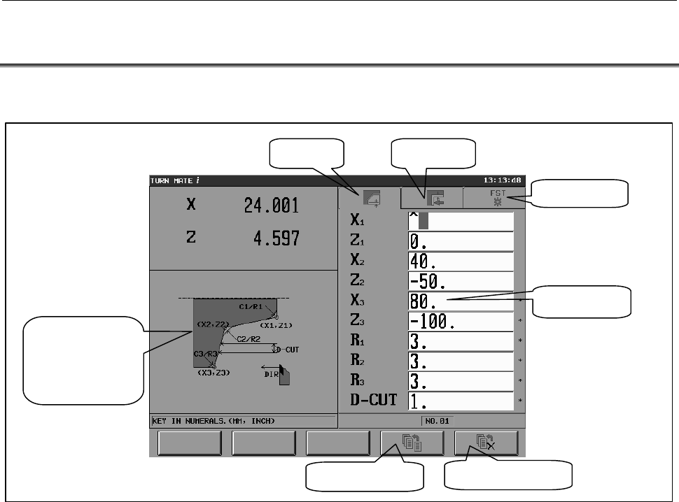
The layout of the input data screen is described below.
Guidance
drawing and
touch screen
for data input
Cycle data
Return Button
Save Button
*
Figure Method
Condition
(1) Guidance drawing
In this area of the screen the guidance drawing of the cutting
cycle being edited is displayed. The guidance drawing of the
cutting cycle changes according to the input data in focus. For
some data this area of the screen is used to input data
(2) Tabs
Input data are divided within Figure, Method, and Condition,
tabs.
(3) Cycle data
Cycle data define cutting conditions, geometry and cutting
methods, of the profile to be cut.
Asterisk symbol “*” next to an input data means that the input
data can be left blank.
(4) Save button
Push SAVE button to save the input data in memory and to
return to the Base Screen.
(5) Return button
Push Return button to cancel input data and to return to the Base
Screen without saving.
Contents Summary of TURN MATE i Operators manual
- Page 1FANUC TURN MATE * OPERATOR’S MANUAL B-64254EN/02
- Page 2• No part of this manual may be reproduced in any form. • All specifications and designs are subject to change without notice. In this manual we have tried as much as possible to describe all the various matters. However, we cannot describe all the matters which must not be done, or which cannot be
- Page 3B-64254EN/02 SAFETY PRECAUTIONS SAFETY PRECAUTIONS When using a machine equipped with the FANUC TURN MATE i, be sure to observe the following safety precautions. s-1
- Page 4SAFETY PRECAUTIONS B-64254EN/02 DEFINITION OF WARNING, CAUTION, AND NOTE This manual includes safety precautions protecting the user and preventing damage to the machine. Precautions are classified into Warning and Caution according to the degree of the risk or the severity of damage. Also, suppleme
- Page 5B-64254EN/02 SAFETY PRECAUTIONS GENERAL WARNINGS AND CAUTIONS To ensure safety while using a machine featuring the TURN MATE i function, observe the following precautions: WARNING 1 Confirm, on the screen, that the data has been entered correctly before proceeding to the next operation. Attempting o
- Page 6
- Page 7B-64254EN/02 TABLE OF CONTENTS TABLE OF CONTENTS SAFETY PRECAUTIONS............................................................................s-1 DEFINITION OF WARNING, CAUTION, AND NOTE ............................................. s-2 GENERAL WARNINGS AND CAUTIONS.................................
- Page 8TABLE OF CONTENTS B-64254EN/02 3 TOOL..................................................................................................... 26 3.1 TOOL SELECTION...................................................................................... 27 3.2 TOOL OFFSET...................................
- Page 9B-64254EN/02 TABLE OF CONTENTS 2 STANDARD CORNER CYCLE ............................................................. 70 2.1 OUTLINE ..................................................................................................... 71 2.2 INPUT DATA ................................................
- Page 10TABLE OF CONTENTS B-64254EN/02 8.3.2 Inner Thread Motions...........................................................................................142 8.3.3 Cutting Method ....................................................................................................144 9 GROOVE CYCLE.........
- Page 11B-64254EN/02 TABLE OF CONTENTS C.4 GROOVE................................................................................................... 191 D LADDER PROGRAM ADAPTATION.................................................. 192 D.1 SETTING OF OPERATION MODE AT POWER ON ...............................
- Page 12
- Page 13I. GENERA
- Page 14
- Page 15B-64254EN/02 GENERAL 1.OVERVIEW OF THIS MANUAL 1 OVERVIEW OF THIS MANUAL This manual describes the functions of "TURN MATE i" for the Series 0i-TC and Series 0i Mate-TC. For other functions, other than TURN MATE i, refer to the operator’s manual for the Series 0i-TC or Series 0i Mate-TC. The specifi
- Page 162.MACHINE OPERATOR’S PANEL GENERAL B-64254EN/02 2 MACHINE OPERATOR’S PANEL Following buttons are necessary to operate TURN MATE i. Please include them on machine operator’s panel prepared by MTB. START Cycle starting button to start cutting cycle STOP Stop button to pause cutting cycle CNC changes i
- Page 17B-64254EN/02 GENERAL 3.SCREEN LAYOUT 3 SCREEN LAYOUT In this chapter the layout of the base screen and the screen hierarchy is outlined. -5-
- Page 183.SCREEN LAYOUT GENERAL B-64254EN/02 3.1 BASE SCREEN LAYOUT The Base Screen is divided in 12 screen areas. By touching each screen area, the related screen appears. (5) (2) (3) (1) (4) (6) (7) (8) (11) (9) (10) (12) (1) Actual Position In this screen area the actual axis position, the load ratio and
- Page 19B-64254EN/02 GENERAL 3.SCREEN LAYOUT (4) Tool number In this screen area the current active tool number is displayed. If this screen area is touched, tool setting screen appears. (5) Machine status In this screen area the state of the machine is displayed. MTN : At least one axis is moving (the CNC
- Page 203.SCREEN LAYOUT GENERAL B-64254EN/02 (12) Soft keys to recall saved cycles Let us assume the cycle number N is displayed. If these buttons are touched, then contiguous cycle N+1 or N-1 is displayed. Touch the buttons to display the previous or next saved cycle NOTE The maximum number of cutting cycl
- Page 21B-64254EN/02 GENERAL 3.SCREEN LAYOUT 3.2 SCREEN NAVIGATION TURN MATE i is based on a three levels screen hierarchy. Level 0 Level 1 Level 2 Spindle speed setting screen [RET] Feedrate setting screen [RET] Tool selection screen Tool data editing screen [RET] [RET] Workpiece coordinate setting screen
- Page 224.CUTTING METHODS GENERAL B-64254EN/02 4 CUTTING METHODS Following 3 cutting methods are available in TURN MATE i. (1) Manual cutting (2) Manual cutting in a limited area (3) Cutting cycle - 10 -
- Page 23B-64254EN/02 GENERAL 4.CUTTING METHODS 4.1 MANUAL CUTTING It is possible to move the tool with the manual pulse generator or the JOG switch. Workflow is as follows. Setting of spindle speed Setting of workpiece coordinate Tool movements with manual pulse generator or JOG - 11 -
- Page 244.CUTTING METHODS GENERAL B-64254EN/02 4.2 MANUAL CUTTING IN A LIMITED AREA It is possible to move the tool in a limited area with manual pulse generator or JOG switch only while manual cutting in a limited area screen is displayed. Restricted area Z X Workflow is as follows. Setting of spindle spee
- Page 25B-64254EN/02 GENERAL 4.CUTTING METHODS 4.3 CUTTING CYCLE Following 2 cutting cycles types are available. The selection of the machining type depends from the cutting depth [D-CUT] value. (1) Cutting cycle with manual in-feeding (D-CUT = 0) (2) Cutting cycle with automatic in-feeding (D-CUT > 0) 4.3.
- Page 264.CUTTING METHODS GENERAL B-64254EN/02 Workflow is as follows. Setting of spindle speed Setting of feedrate Selection of tool (Setting of offset) Setting of workpiece coordinate Setting of cycle data Cycle starting Yes D-CUT>0 No Cycle machining Cycle machining with manual in-feed with automatic in-
- Page 27B-64254EN/02 GENERAL 5.NOTES ON OPERATIONS 5 NOTES ON OPERATIONS Before operating TURN MATE i read carefully following notes. - 15 -
- Page 285.NOTES ON OPERATIONS GENERAL B-64254EN/02 5.1 SPECIFICATION OF T CODE FOR TOOL SELECTION In TURN MATE i T code for tool selection has following pattern: Txyxy ( 4 digit number) It means that tool number and tool offset number shall be the same. Up to 16 tools can be registered in TURN MATE i, from
- Page 29B-64254EN/02 GENERAL 5.NOTES ON OPERATIONS 5.4 MANUAL INTERVENTION DURING CUTTING CYCLES If a cutting cycle is stopped by feed hold then do not execute any manual intervention. There is no guarantee the tool will returns to the position where the cutting cycle has been stopped. WARNING If a cutting
- Page 306.MANDATORY PARAMETERS GENERAL B-64254EN/02 6 MANDATORY PARAMETERS In order to run TURN MATE i it is necessary to set the following parameters. (1) P3112#0(SGD)=0 This parameter setting disables servo waveform display. If this parameter is set to 1, then no graphic display function other than servo
- Page 31II. OPERATIO
- Page 32
- Page 33B-64254EN/02 OPERATION 1.SPINDLE 1 SPINDLE It is necessary to set the spindle speed before any cutting operation. If the spindle speed screen area on the Base Screen is pushed, then the spindle speed setting screens are displayed. Following screens are available to specify the spindle data. (1) Sett
- Page 341.SPINDLE OPERATION B-64254EN/02 1.1 CONSTANT SURFACE SPEED OFF If tab CSS OFF is selected, then following screen is displayed. On this screen the spindle speed is specified in rotations per minute. CSS OFF Gear Number CSS ON Return to the SET Base screen. The workflow is as follows. (1) Input into
- Page 35B-64254EN/02 OPERATION 1.SPINDLE 1.2 CONSTANT SURFACE SPEED ON If tab CSS ON is selected, then following screen is displayed. On this screen the spindle speed is specified in mm/min. SET The workflow is as follows. (1) Input into the data area named S-CSS the desired spindle speed, then push INPUT (
- Page 361.SPINDLE OPERATION B-64254EN/02 1.3 GEAR NUMBER If tab Gear-Number is selected, then following screen is displayed. Gear number from 1 to 4 can be specified on this screen. Four icon buttons are displayed on the left side of the screen. To specify the desired gear number it is necessary to push the
- Page 37B-64254EN/02 OPERATION 2.FEEDRATE 2 FEEDRATE It is necessary to specify the feedrate before any cutting operation. If the feedrate screen area on the Base Screen is pushed, then the feedrate setting screen is displayed. To return to the Base Screen push the RET button at the bottom right of the scre
- Page 383.TOOL OPERATION B-64254EN/02 3 TOOL If the tool screen area on the Base Screen is pushed, then the tool selection screen is displayed. - 26 -
- Page 39B-64254EN/02 OPERATION 3.TOOL 3.1 TOOL SELECTION The tool number that has been selected and the corresponding tool offset values are displayed on the upper side of the screen. To select a tool, push the corresponding button number and then push SET button. Tool number will be stored into the corresp
- Page 403.TOOL OPERATION B-64254EN/02 3.2 TOOL OFFSET After selecting the tool if the Tool Edit button is pushed, then tool offset set screen is displayed. In this screen is possible to edit tool data for the selected tool. 3.2.1 Direct Input of Tool Offset Values The tool data include tool nose radius R, v
- Page 41B-64254EN/02 OPERATION 3.TOOL
Move to Incremental tab. It is possible to add or to subtract a certain amount from the actual offset value and tool nose radius by inputting a value into the data area OFS_X+ , OFS_Z+, and R+ and then pushing INPUT ( ) key. - Page 423.TOOL OPERATION B-64254EN/02
Move to Absolute tab or Incremental tab. Input the corresponding value of virtual tool tip position into the data area TIP, and then push INPUT ( ) key. To store the newly input virtual tool tip into the corresponding System Variables of t - Page 43B-64254EN/02 OPERATION 3.TOOL 3.2.2 Measurement of Tool Offset Values If Measure tab is displayed then X and Z coordinates values of the tool offset can be directly measured. NOTE Only the tool with the corresponding number assigned to system variable #4120 shall be directly measured. In other words
- Page 443.TOOL OPERATION B-64254EN/02 X and Z coordinates values of the tool offset can be measured following the procedure described below.
(1) Measure the diameter of the workpiece. (2) Touch with the tool the workpiece side moving along X axis. (3) Insert the value of - Page 45B-64254EN/02 OPERATION 3.TOOL Example) Below a numerical example on how to set tool offset data. 10 Actual Position at the touching point: X=45.0 (value of system variable #5041) Z=15.0 (value of system variable #5042) φ 40 Current tool offset value: X=30.0 Z=5.0 Origin of workpiece coordinate syste
- Page 464.WORKPIECE COORDINATE SYSTEMOPERATION B-64254EN/02 4 WORKPIECE COORDINATE SYSTEM It is necessary to set the workpiece coordinate system each time a new workpiece is attached to the chuck before start cutting. It is assumed that the coordinate system of TURN MATE i is as schematized in the picture b
- Page 47B-64254EN/02 OPERATION4.WORKPIECE COORDINATE SYSTEM Example of screen of Z coordinates value The components X and Z of the workpiece coordinate system can be measured following the procedure described below.
(1) Measure the diameter of the workpiece (2) Make the - Page 484.WORKPIECE COORDINATE SYSTEMOPERATION B-64254EN/02 Example) Below a numerical example on how to set workpiece coordinate system data. 10 φ 40 +Z Origin of workpiece coordinate system +X (1) Measure the diameter of the workpiece. (2) Make the spindle rotate and touch with the tool the side surface o
- Page 49B-64254EN/02 OPERATION5.MANUAL CUTTING IN A LIMITED AREA 5 MANUAL CUTTING IN A LIMITED AREA The range of movement of the tool when moving with JOG switch or manual pulse generator can be restricted in a limited area. The range of the movement of the tool is permitted within a rectangular area. Movem
- Page 506.CUTTING CYCLE OPERATION B-64254EN/02 6 CUTTING CYCLE - 38 -
- Page 51B-64254EN/02 OPERATION 6.CUTTING CYCLE 6.1 CREATION OF CUTTING CYCLE Below the workflow to create a new cutting cycle is described. (1) To display the cutting cycle selection screen push the guidance drawing on the Base Screen. (2) To select the desired cycle menu push on the corresponding drawing i
- Page 526.CUTTING CYCLE OPERATION B-64254EN/02 6.2 EDITING CUTTING CYCLE Below the workflow to edit a cutting cycle is described. (1) To display the input data screen of the cutting cycle push the cycle data area on the Base Screen. (2) Data can be edited on the cycle input data screen. (3) To save the data
- Page 53B-64254EN/02 OPERATION 6.CUTTING CYCLE 6.3 CYCLE INPUT DATA SCREEN The layout of the input data screen is described below. Figure Method Condition * Cycle data Guidance drawing and touch screen for data input Save Button Return Button (1) Guidance drawing In this area of the screen the guidance draw
- Page 547.FREE FIGURE OPERATION B-64254EN/02 7 FREE FIGURE - 42 -
- Page 55B-64254EN/02 OPERATION 7.FREE FIGURE 7.1 FREE FIGURE INPUT DATA SCREEN Pushing on the guidance drawing screen area the following screen appears. (1) (2) (3) (4) (5) (6) [CAL] [DEL] [RET] Free figure input data screen The screen is composed of the following six areas. (1) List of figure elements This
- Page 567.FREE FIGURE OPERATION B-64254EN/02 NOTE The maximum number of figure elements for each free figure cycle is 10. If the parameter No.9104 #0 #1 is set to 1, it is possible to extend the maximum number from 10 to 15 or 30. But, it takes longer time to start a free figure cycle than 10 elements. - 44
- Page 57B-64254EN/02 OPERATION 7.FREE FIGURE 7.1.1 List of Figure Elements Each figure element is characterized by a set of input data. The input data value is assigned by inputting the numerical value into the corresponding edit box and then pushing the INPUT ( ). The icons below represent each figure elem
- Page 587.FREE FIGURE OPERATION B-64254EN/02 7.1.2 Figure Elements Button The following figure elements buttons are available to define the free figure. Nine different figure elements are available. (1) Straight line X, Z: It is defined specifying the end coordinates (X,Z). (2) Straight line X, A: It is def
- Page 59B-64254EN/02 OPERATION 7.FREE FIGURE 7.1.3 Drawing Area The figure being edited is displayed. Start Point Figure element where the cursor is located The figure is updated in the following cases. (1) When a new graphic element is inserted at the bottom of the figure element list. (2) When CAL soft ke
- Page 607.FREE FIGURE OPERATION B-64254EN/02 7.1.6 Soft Key (1) CAL soft key: Soft key to update the drawing after a figure element has been modified. In the following cases it is necessary to update the figure. • Insertion of a new figure element not at the bottom of the list. • Alteration of a figure elem
- Page 61B-64254EN/02 OPERATION 7.FREE FIGURE 7.2 CREATION OF A NEW FREE FIGURE (1) When the free figure input screen is opened, the start point block is inserted automatically. (2) The cursor moves to the next edit box when data is input, and then MDI INPUT ( ) key is pushed. (3) The figure being edited is
- Page 627.FREE FIGURE OPERATION B-64254EN/02 7.3 EDITING A FREE FIGURE (1) The cursor can be moved to any edit box by using cursor keys (←, →, ↑, ↓). (2) Data can be altered by inserting a new value and then pushing the INPUT ( ) key. (3) If any of the figure elements button is pushed, then the correspondin
- Page 63B-64254EN/02 OPERATION 7.FREE FIGURE 7.4 STORAGE OF A FREE FIGURE To store the figure is necessary to push the soft key RET. After pressing RET two cases are possible. (1) In case of error The cursor moves to the edit box of the undefined graphic element and a pop up window appears showing the error
- Page 647.FREE FIGURE OPERATION B-64254EN/02 (2) In case of no error The final shape of the part is displayed in guidance drawing area. The area of the part material is dark painted. To return to the base screen and to save the free figure created is necessary to push soft key SAVE. To return to the base sc
- Page 65B-64254EN/02 OPERATION 8.LANGUAGE, UNIT, FINISHING AMOUNT 8 LANGUAGE, UNIT, FINISHING AMOUNT If the Setting button on the Base Screen is pushed, then set screen is displayed. Within the set screen is possible to set the language, the measurement unit and to specify the default finish amount. - 53 -
- Page 668.LANGUAGE, UNIT, FINISHING AMOUNT OPERATION B-64254EN/02 8.1 LANGUAGE SELECTION To change the language of the messages it is necessary to push the button corresponding to the desired language. Selected language NOTE Soon after the language selection it is necessary to switch off and then on the CNC
- Page 67B-64254EN/02 OPERATION 8.LANGUAGE, UNIT, FINISHING AMOUNT 8.2 INCH/METRIC SELECTION Measurement unit can be switched by pushing the corresponding button. Selected unit. NOTE After switching measurement unit, the software does not convert the data of the cycles already programmed into the new measure
- Page 688.LANGUAGE, UNIT, FINISHING AMOUNT OPERATION B-64254EN/02 8.3 DEFAULT FINISHING AMOUNT VALUES For the following cutting cycles is possible to specify a default finish amount value: (1) Standard Corner cycle (2) Taper cycle (3) Arc of circle cycle (4) Free figure cycle (5) Grooving cycle The data ins
- Page 69B-64254EN/02 OPERATION 9.ALARMS AND OPERATOR MESSAGES 9 ALARMS AND OPERATOR MESSAGES If the message display area on the bottom left side corner of the Base Screen is pushed, then alarm screen is displayed. ALARM MSG If tab ALARM is pushed then NC alarm and the external alarm messages are displayed.
- Page 7010.CALCULATOR FUNCTION OPERATION B-64254EN/02 10 CALCULATOR FUNCTION When numeric data is input, expressions for arithmetic operations, trigonometric functions, square root calculations, and so forth can be input for calculation. 1) Applications The calculator function can be used for cycle data inp
- Page 71B-64254EN/02 OPERATION 10.CALCULATOR FUNCTION • Trigonometric functions (sine, cosine, tangent, arcsine, arccosine, arctangent) Trigonometric function calculations are made using the key operations described below. The result of a calculation is displayed at the cursor position for input data. (1) S
- Page 7210.CALCULATOR FUNCTION OPERATION B-64254EN/02 • Logarithmic functions (common logarithm, natural logarithm) Logarithmic function calculations are made using the key operations described below. The result of a calculation is displayed at the cursor position for input data. (1) Common logarithm : LOG[
- Page 73III. CYCLE MACHININ
- Page 74
- Page 75B-64254EN/02 CYCLE MACHINING 1.TYPE OF CUTTING CYCLES 1 TYPE OF CUTTING CYCLES The selection screen of the cycles is composed of CYCLE tab and DETAIL tab. 1.1 GENERAL GROUP OF CUTTING CYCLES ..........................64 1.2 DETAILED GROUP OF CUTTING CYCLES .........................65 - 63 -
- Page 761.TYPE OF CUTTING CYCLES CYCLE MACHINING B-64254EN/02 1.1 GENERAL GROUP OF CUTTING CYCLES The cutting cycles are grouped in families of cutting cycles. CYCLE DETAIL (4) (1) (7) (8) (2) (3) (9) (5) (6) Within the CYCLE tab is possible to select the following families of cutting cycles. (1) Standard c
- Page 77B-64254EN/02 CYCLE MACHINING 1.TYPE OF CUTTING CYCLES 1.2 DETAILED GROUP OF CUTTING CYCLES The DETAIL tab is automatically displayed after selecting the desired family of cutting cycle. The following DETAIL tabs are displayed depending from the selected family of cutting cycle (For Face cycle there
- Page 781.TYPE OF CUTTING CYCLES CYCLE MACHINING B-64254EN/02 (2) Face corner cycles familiy (six cycles) • Outer corner R/chamfer C • Outer back corner R/chamfer C • Inner corner R/chamfer C (3) Taper cycles familiy (three cycles) • Outer taper • Inner taper • Outer back taper - 66 -
- Page 79B-64254EN/02 CYCLE MACHINING 1.TYPE OF CUTTING CYCLES (4) Radius cycles familiy (six cycles) • Convex/concave outer radius • Convex/concave outer back radius • Convex/concave inner radius (5) Free figure cycles familiy (three cycles) • Outer free figure • Outer back free figure • Inner free figure -
- Page 801.TYPE OF CUTTING CYCLES CYCLE MACHINING B-64254EN/02 (6) Thread cycles familiy (four cycles) • Outer thread • Inner thread • Outer thread repair • Inner thread repair (7) Groove cycles familiy (three cycles) • Outer Groove • Inner Groove • Face Groove - 68 -
- Page 81B-64254EN/02 CYCLE MACHINING 1.TYPE OF CUTTING CYCLES (8) Hole cycles familiy (two cycles) • Drill cycle • Tap cycle - 69 -
- Page 822.STANDARD CORNER CYCLE CYCLE MACHINING B-64254EN/02 2 STANDARD CORNER CYCLE 2.1 OUTLINE...................................................................................71 2.2 INPUT DATA ............................................................................73 2.3 TOOL CUTTING MOTIONS .......
- Page 83B-64254EN/02 CYCLE MACHINING 2.STANDARD CORNER CYCLE 2.1 OUTLINE The standard corner cycle is characterized by following properties. (1) The standard corner shape is defined by specifying start point, end point and radius or camfer amount. (2) The cycle is used to cut a rectangular corner. (3) The c
- Page 842.STANDARD CORNER CYCLE CYCLE MACHINING B-64254EN/02 Outer +Z C Start point +X R Cutting area End point Outer back +Z C Start point +X Cutting area R End point Inner +Z End point Cutting area R +X Start point C - 72 -
- Page 85B-64254EN/02 CYCLE MACHINING 2.STANDARD CORNER CYCLE 2.2 INPUT DATA In the following description the input data for standard outer corner chamfer C cycle is explained in detail. As the meaning of the data input for the other standard corner cycles is the same they are not explained in this document.
- Page 862.STANDARD CORNER CYCLE CYCLE MACHINING B-64254EN/02 Item Meaning Tab Mandatory Note CSS Constant surface speed COND. × ON (1) OFF (2) S Spindle speed COND. × S-MAX Maximum spindle speed COND. × Display only if CSS=1 G The gear number is specified with COND. × 1-4 is specified. the button on touch s
- Page 87B-64254EN/02 CYCLE MACHINING 2.STANDARD CORNER CYCLE 2.3 TOOL CUTTING MOTIONS In this section will be explained in detail tool cutting motions of Outer Corner Cycle. The tool cutting motion of the others Corner Cycles can be deducted for symmetry. 2.3.1 Rough Cutting Motions The tool cutting motions
- Page 882.STANDARD CORNER CYCLE CYCLE MACHINING B-64254EN/02 Clearance Z Clearance X Outer back Clearance X Clearance Z Inner - 76 -
- Page 89B-64254EN/02 CYCLE MACHINING 2.STANDARD CORNER CYCLE 1. Depth of cut D-CUT=0, cutting direction DIR=Z, tool in [E]+[F] (1) The tool moves from the initial position, somewhere in [E]+[F], in cutting feedrate until the edge of the programmed figure is reached. (2) The tool retracts by the escape amoun
- Page 902.STANDARD CORNER CYCLE CYCLE MACHINING B-64254EN/02 3. Depth of cut D-CUT>0, cutting direction DIR=Z, tool in [C]+[G]+[H]+[I] (1) The tool moves from the initial position, somewhere in [C]+[G]+[H]+[I], to P2 moving in rapid traverse first along the Z axis and then along the X axis. (2) The tool ret
- Page 91B-64254EN/02 CYCLE MACHINING 2.STANDARD CORNER CYCLE 4. Depth of cut D-CUT>0, cutting direction DIR=Z, tool in [F] (1) The tool moves from the initial position, somewhere in [F], to the edge of clearance Z moving in rapid traverse first along the Z axis. (2) The tool moves in cutting feedrate, along
- Page 922.STANDARD CORNER CYCLE CYCLE MACHINING B-64254EN/02 5. Depth of cut D-CUT=0, cutting direction DIR=X, tool in [E]+[H] (1) The tool moves from the initial position, somewhere in [E]+[H], in cutting feedrate until the edge of the programmed figure is reached. (2) The tool retracts by the escape amoun
- Page 93B-64254EN/02 CYCLE MACHINING 2.STANDARD CORNER CYCLE 7. Depth of cut D-CUT>0, cutting direction DIR=X, tool in [C]+[F]+[G]+[I] (1) The tool moves from the initial position, somewhere in [C]+[F]+[G]+[I], to P2 moving in rapid traverse first along the X axis and then along the Z axis. (2) The tool ret
- Page 942.STANDARD CORNER CYCLE CYCLE MACHINING B-64254EN/02 8. Depth of cut D-CUT>0, cutting direction DIR=X, tool in [H] (1) The tool moves from the initial position, somewhere in [H], to the edge of clearance X moving in rapid traverse along the X axis. (2) The tool moves in cutting feedrate, along the X
- Page 95B-64254EN/02 CYCLE MACHINING 2.STANDARD CORNER CYCLE 2.3.2 Finish Cutting Motions The tool cutting motions are primarly influenced by following characteristics: • Cutting direction (DIR); • Roughing, Finishing operation (R+F); The space around the workpiece is divided in 5 areas named [A], [B], [E],
- Page 962.STANDARD CORNER CYCLE CYCLE MACHINING B-64254EN/02 Clearance Z Clearance Z Outer back Clearance X Clearance Z Inner - 84 -
- Page 97B-64254EN/02 CYCLE MACHINING 2.STANDARD CORNER CYCLE 1. Finishing only, cutting direction DIR=Z, tool in [B] (1) The tool moves from the initial position, somewhere in [B], to P1 moving in rapid traverse first along the Z axis and then along the X axis. (2) From P1 the tools moves in cutting feed al
- Page 982.STANDARD CORNER CYCLE CYCLE MACHINING B-64254EN/02 3. Finishing only, cutting direction DIR=X, tool in [B] (1) The tool moves from the initial position, somewhere in [B], to P3 moving in rapid traverse first along the X axis and then along the Z axis. (2) From P3 the tools moves in cutting feed al
- Page 99B-64254EN/02 CYCLE MACHINING 3.FACE CORNER CYCLE 3 FACE CORNER CYCLE 3.1 OUTLINE...................................................................................88 3.2 INPUT DATA ............................................................................90 3.3 TOOL CUTTING MOTIONS ...............
- Page 1003.FACE CORNER CYCLE CYCLE MACHINING B-64254EN/02 3.1 OUTLINE The face corner cycle is characterized by following properties. (1) The face corner shape is defined by specifying corner point and radius or camfer amount. (2) The tool moves parallel to the final shape (3) Depending from the value of D-C
- Page 101B-64254EN/02 CYCLE MACHINING 3.FACE CORNER CYCLE Outer face corner R/ corner C +Z +X R/C 45 degree Corner point Outer back corner R / corner C +Z +X R/C 45 degree Corner point Inner corner R / corner C +Z Corner point 45 degree +X R/C - 89 -
- Page 1023.FACE CORNER CYCLE CYCLE MACHINING B-64254EN/02 3.2 INPUT DATA In the following description the input data for face outer corner chamfer cycle is explained in detail. As the meaning of the data input for the other face corner cycles is the same other face corner cycles are not explained in this doc
- Page 103B-64254EN/02 CYCLE MACHINING 3.FACE CORNER CYCLE 3.3 TOOL CUTTING MOTIONS In this section will be explained in detail tool cutting motions of Face Corner Cycle Chamfer C. The tool cutting motion of the others Face Corner Cycles can be deducted for symmetry. The tool cutting motions are primarly infl
- Page 1043.FACE CORNER CYCLE CYCLE MACHINING B-64254EN/02 Outer back Inner - 92 -
- Page 105B-64254EN/02 CYCLE MACHINING 3.FACE CORNER CYCLE 1. Depth of Cut D-CUT=0, Tool in [F] (1) The tool moves from the initial position (XS, ZS), somewhere in [F], in cutting feedrate until position (XS, Z). (2) The tool moves parallel to the programmed figure, in cutting feedrate until position (X, Zn).
- Page 1063.FACE CORNER CYCLE CYCLE MACHINING B-64254EN/02 2. Chamfer, Depth of Cut D-CUT=0, Tool in [C] (1) The tool moves from the initial position (XS, ZS), somewhere in [C], along the X axis in rapid traverse until (X_min, ZS). (2) The tool moves in cutting feed along the Z axis until (X_min, Z). (3) The
- Page 107B-64254EN/02 CYCLE MACHINING 3.FACE CORNER CYCLE 3. Radius, Depth of Cut D-CUT=0, Tool in [C] (1) The tool moves from the initial position (XS, ZS), somewhere in [C], along the X axis in rapid traverse until (X_min, ZS). (2) The tool moves in cutting feed along the Z axis until (X_min, Z). (3) The t
- Page 1083.FACE CORNER CYCLE CYCLE MACHINING B-64254EN/02 4. Depth of Cut D-CUT>0, Tool in [C]+[G] (1) The tool moves from the initial position, somewhere in [C]+[G], to P2 moving in rapid traverse first along the Z axis and then along the X axis. (2) The tool retract in rapid traverse along the X axis by −D
- Page 109B-64254EN/02 CYCLE MACHINING 3.FACE CORNER CYCLE 5. Depth of Cut D-CUT>0, Tool in [F] (1) The tool moves from the initial position, somewhere in [F], to the edge of clearance Z moving in rapid traverse along the Z axis. (2) The tool moves in cutting feedrate, along the Z axis, until the position Z.
- Page 1104.TAPER CYCLE CYCLE MACHINING B-64254EN/02 4 TAPER CYCLE 4.1 OUTLINE...................................................................................99 4.2 INPUT DATA ..........................................................................101 4.3 TOOL CUTTING MOTIONS ............................
- Page 111B-64254EN/02 CYCLE MACHINING 4.TAPER CYCLE 4.1 OUTLINE The taper cycle is characterized by following properties. (1) The taper shape is defined by specifying three intersection points (1 - 3). (2) On each intersection point is possible to specify a corner radius or a chamfer. (3) 2nd and 3rd point c
- Page 1124.TAPER CYCLE CYCLE MACHINING B-64254EN/02 Outer Point 1 +Z Point 2 +X Point 3 Cutting area Outer back Point 1 Point 2 +Z Cutting area +X Point 3 Inner +Z Point 3 Cutting area Point 2 +X Point 1 - 100 -
- Page 113B-64254EN/02 CYCLE MACHINING 4.TAPER CYCLE 4.2 INPUT DATA In the following description the input data for outer taper cycle is explained in detail. As the meaning of the data input for the other for taper cutting cycles is the same other taper cycles are not explained in this document. Input data fo
- Page 1144.TAPER CYCLE CYCLE MACHINING B-64254EN/02 Item Meaning Tab Mandatory Note R2/C2 Corner R/chamfering C at FIG × The selection between corner intersection point 2 and chamfer is done via touch screen button. The guidance drawing changes according to the selection. R3/C3 Corner R/chamfering C at FIG ×
- Page 115B-64254EN/02 CYCLE MACHINING 4.TAPER CYCLE 4.3 TOOL CUTTING MOTIONS In this section will be explained in detail tool cutting motions of Outer Taper Cycle. The tool cutting motion of the others Taper Cycles can be deducted for symmetry. 4.3.1 Rough Cutting Motions The tool cutting motions are primarl
- Page 1164.TAPER CYCLE CYCLE MACHINING B-64254EN/02 Clearance Z [A] [C] P1 [E] [F] Clearance X P3 P2 [G] [H] [I] Outer Outer back - 104 -
- Page 117B-64254EN/02 CYCLE MACHINING 4.TAPER CYCLE Inner 1. Depth of cut D-CUT=0, cutting direction DIR=Z, tool in [E]+[F] (1) The tool moves from the initial position, somewhere in [E]+[F], in cutting feedrate until the edge of the programmed figure is reached. (2) The tool retracts by the escape amount (E
- Page 1184.TAPER CYCLE CYCLE MACHINING B-64254EN/02 2. Depth of cut D-CUT=0, cutting direction DIR=Z, tool in [C]+[G]+[H]+[I] (1) The tool moves from the initial position, somewhere in [C]+[G]+[H]+[I], to P1 moving in rapid traverse first along the Z axis and then along the X axis. (2) From P1 the tools move
- Page 119B-64254EN/02 CYCLE MACHINING 4.TAPER CYCLE 3. Depth of cut D-CUT>0, cutting direction DIR=Z, tool in [C]+[G]+[H]+[I] (1) The tool moves from the initial position, somewhere in [C]+[G]+[H]+[I], to P2 moving in rapid traverse first along the Z axis and then along the X axis. (2) The tool retract in ra
- Page 1204.TAPER CYCLE CYCLE MACHINING B-64254EN/02 4. Depth of cut D-CUT>0, cutting direction DIR=Z, tool in [F] (1) The tool moves from the initial position, somewhere in [F], to the edge of clearance Z moving in rapid traverse first along the Z axis. (2) The tool moves in cutting feedrate, along the Z axi
- Page 121B-64254EN/02 CYCLE MACHINING 4.TAPER CYCLE 5. Depth of cut D-CUT=0, cutting direction DIR=X, tool in [E]+[H] (1) The tool moves from the initial position, somewhere in [E]+[H], in cutting feedrate until the edge of the programmed figure is reached. (2) The tool retracts by the escape amount (ESCPAMT
- Page 1224.TAPER CYCLE CYCLE MACHINING B-64254EN/02 7. Depth of cut D-CUT>0, cutting direction DIR=X, tool in [C]+[F]+[G]+[I] (1) The tool moves from the initial position, somewhere in [C]+[F]+[G]+[I], to P2 moving in rapid traverse first along the X axis and then along the Z axis. (2) The tool retract in ra
- Page 123B-64254EN/02 CYCLE MACHINING 4.TAPER CYCLE 8. Depth of cut D-CUT>0, cutting direction DIR=X, tool in [H] (1) The tool moves from the initial position, somewhere in [H], to the edge of clearance X moving in rapid traverse along the X axis. (2) The tool moves in cutting feedrate, along the X axis, unt
- Page 1244.TAPER CYCLE CYCLE MACHINING B-64254EN/02 4.3.2 Finish Cutting Motions The tool cutting motions are primarly influenced by following characteristics: • Cutting direction (DIR); • Roughing, Finishing operation (R+F); The space around the workpiece is divided in 5 areas named [A], [B], [E], and clear
- Page 125B-64254EN/02 CYCLE MACHINING 4.TAPER CYCLE Outer back Inner - 113 -
- Page 1264.TAPER CYCLE CYCLE MACHINING B-64254EN/02 1. Finishing only, cutting direction DIR=Z, tool in [B] (1) The tool moves from the initial position, somewhere in [B], to P1 moving in rapid traverse first along the Z axis and then along the X axis. (2) From P1 the tools moves in cutting feed along the pr
- Page 127B-64254EN/02 CYCLE MACHINING 4.TAPER CYCLE 3. Finishing only, cutting direction DIR=X, tool in [B] (1) The tool moves from the initial position, somewhere in [B], to P3 moving in rapid traverse first along the X axis and then along the Z axis. (2) From P3 the tools moves in cutting feed along the pr
- Page 1284.TAPER CYCLE CYCLE MACHINING B-64254EN/02 4. Roughing + finishing, cutting direction DIR=X, tool in [B] The following description refers to tool cutting motions described in Subsections 7 and 8 of rough cutting motions. (1) The tool moves from position Ez, to P1 moving in rapid traverse first along
- Page 129B-64254EN/02 CYCLE MACHINING 5.RADIUS CYCLE 5 RADIUS CYCLE 5.1 OUTLINE.................................................................................118 5.2 INPUT DATA ..........................................................................120 5.3 TOOL CUTTING MOTIONS ...........................
- Page 1305.RADIUS CYCLE CYCLE MACHINING B-64254EN/02 5.1 OUTLINE Radius cycle is characterized by following properties. (1) The radius shape is defined by specifying three line and one arc. (2) It is possible to select the cutting direction between -Z, +Z, +X, -X. (3) Depending from the value of D-CUT it is
- Page 131B-64254EN/02 CYCLE MACHINING 5.RADIUS CYCLE Inner concave Cutting area +Z Line3 Line2 Arc +X Line1 Outer back convex +Z Line1 Line2 +X Arc Cutting area Line3 Outer back concave Line1 +Z Arc Line2 +X Cutting area Line3 - 119 -
- Page 1325.RADIUS CYCLE CYCLE MACHINING B-64254EN/02 5.2 INPUT DATA In the following description the input data for convex outer radius cycle is explained in detail. As the meaning of the data input for the other radius cycles is the same other radius cycles are not explained in this document. Input data for
- Page 133B-64254EN/02 CYCLE MACHINING 5.RADIUS CYCLE Item Meaning Tab Mandatory Note FIN-Z Finishing amount Z METH. × The default value of FIN-Z is specified in the set screen. T Tool number COND. × F Feedrate COND. × CSS Constant surface speed COND. × An initial value is invalid. ON (1) OFF (2) S Spindle sp
- Page 1346.FACE CYCLE CYCLE MACHINING B-64254EN/02 6 FACE CYCLE 6.1 OUTLINE.................................................................................123 6.2 INPUT DATA ..........................................................................124 6.3 TOOL CUTTING MOTIONS ...............................
- Page 135B-64254EN/02 CYCLE MACHINING 6.FACE CYCLE 6.1 OUTLINE The face cycle is characterized by following properties. (1) The face shape is defined by specifying the end point, witdh and height of cutting area. (2) Depending from the value of D-CUT it is possible to machine by manual in-feeding or automati
- Page 1366.FACE CYCLE CYCLE MACHINING B-64254EN/02 6.2 INPUT DATA Data input for face cycle Item Meaning Tab Mandatory Note X0 Height of the area to cut FIG ○ Absolute coordinate X X coordinate of end point FIG ○ Absolute coordinate Z Z coordinate of end point FIG ○ Absolute coordinate E Width of the area to
- Page 137B-64254EN/02 CYCLE MACHINING 6.FACE CYCLE 6.3 TOOL CUTTING MOTIONS The tool cutting motions are primarly influenced by following characteristics: • Tool position at the time Cycle Start is pressed; • Depth of cut (D-CUT); The space around the workpiece is divided in 7 areas named [A], [C], [E], [F],
- Page 1386.FACE CYCLE CYCLE MACHINING B-64254EN/02 1. Depth of Cut D-CUT=0, Tool in [E]+[H] (1) The tool moves from the initial position, somewhere in [E]+[H], in cutting feedrate until the edge of the programmed figure is reached. (2) The tool retracts by the escape amount (ESCPAMT) specified in parameter N
- Page 139B-64254EN/02 CYCLE MACHINING 6.FACE CYCLE 2. Depth of Cut D-CUT>0, Cutting Direction DIR=X, Tool in [C]+[F]+[G]+[I] (1) The tool moves from the initial position, somewhere in [C]+[F]+[G]+[I], to P2 moving in rapid traverse first along the X axis and then along the Z axis. (2) The tool retract in rap
- Page 1406.FACE CYCLE CYCLE MACHINING B-64254EN/02 3. Depth of Cut D-CUT>0, Cutting Direction DIR=X, Tool in [H] (1) The tool moves from the initial position, somewhere in [H], to the edge of clearance X moving in rapid traverse along the X axis. (2) The tool moves in cutting feedrate, along the X axis, unti
- Page 141B-64254EN/02 CYCLE MACHINING 7.FREE FIGURE CYCLE 7 FREE FIGURE CYCLE 7.1 OUTLINE.................................................................................130 7.2 INPUT DATA ..........................................................................131 7.3 TOOL CUTTING MOTIONS .................
- Page 1427.FREE FIGURE CYCLE CYCLE MACHINING B-64254EN/02 7.1 OUTLINE The free figure cycle is characterized by following properties. (1) It is possible to select the cutting direction between -Z, +Z, +X, -X. (2) Free figures shapes containing up to 10 elements can be edited. (3) Depending from the value of
- Page 143B-64254EN/02 CYCLE MACHINING 7.FREE FIGURE CYCLE 7.2 INPUT DATA In the following description the input data for outer free figure cycle is explained in detail. As the meaning of the data input for the others for free figure cycles is the same they are not explained in this document. Screen area wher
- Page 1447.FREE FIGURE CYCLE CYCLE MACHINING B-64254EN/02 Item Meaning Tab Mandatory Note G The gear number is specified with COND. × 1-4 is specified. the button on touch screen. 7.3 TOOL CUTTING MOTIONS The tool cutting motions are equal to the tool cutting motions of the taper cylce. Refer to the tool cut
- Page 145B-64254EN/02 CYCLE MACHINING 8.THREAD CYCLE 8 THREAD CYCLE 8.1 OUTLINE.................................................................................134 8.2 INPUT DATA ..........................................................................135 8.2.1 Input Data Thread Cycle ......................
- Page 1468.THREAD CYCLE CYCLE MACHINING B-64254EN/02 8.1 OUTLINE There are two kinds of thread cycle of outer thread and inner thread, and is characterized by following properties. (1) Thread shape can be defined by starting point, end point, pitch and depth of thread. (2) A straight and taper threading are
- Page 147B-64254EN/02 CYCLE MACHINING 8.THREAD CYCLE 8.2 INPUT DATA 8.2.1 Input Data Thread Cycle In the following the input data for outer thread cycle is explained in detail. As the meaning of the data input for thread cycles is the same other thread cycles are not explained in this document. The picture b
- Page 1488.THREAD CYCLE CYCLE MACHINING B-64254EN/02 Item Meaning Tab Mandatory Note METH Following cutting methods can be METH × The guidance drawing specified. changes according to the 1: Constant amount of cutting and selection. single-edged cutting As default cutting constant 2: Constant amount of cuttin
- Page 149B-64254EN/02 CYCLE MACHINING 8.THREAD CYCLE 8.2.2 Input Data Thread Repair Cycle In the following the input data for outer thread repair cycle is explained in detail. As the meaning of the data input for outer thread repair cycles is the same other they are not explained in this document. Input data
- Page 1508.THREAD CYCLE CYCLE MACHINING B-64254EN/02 Item Meaning Tab Mandatory Note with the button on the touch screen. according to the selection. Cutting direction - Z (1) As default cutting direction is - Z. Cutting direction + Z (2) FIN Finishing amount METH × T Tool number COND × S Spindle speed COND
- Page 151B-64254EN/02 CYCLE MACHINING 8.THREAD CYCLE (4) Push [SET] key. (The value of current position Z is set in input item “SET-Z") (5) Move away the tool from the piece, over the surface clearance (parameter No.9221), along the X axis and then move the tool along the Z axis over the entrance clearance (
- Page 1528.THREAD CYCLE CYCLE MACHINING B-64254EN/02 8.3 TOOL CUTTING MOTION 8.3.1 Outer Thread Motions The space around the workpiece is divided in 2 areas named [A], [B]. If at the time cycle start is pressed the tool is somewhere into the area [A] then an alarm is displayed. Clearance Z [A] Clearance X P2
- Page 153B-64254EN/02 CYCLE MACHINING 8.THREAD CYCLE Tool motions of outer thread is as follows. (1) The tool moves from the initial position, somewhere in [B], to P2 in rapid traverse first along the Z axis and then along the X axis. (2) From P2 the threading is realized according to the depth of cut and th
- Page 1548.THREAD CYCLE CYCLE MACHINING B-64254EN/02 8.3.2 Inner Thread Motions The space around the workpiece is divided in 2 areas named [A], [B]. If at the time cycle start is pressed the tool is somewhere into the area [A] then an alarm is displayed. [B] P2 Clearance X [A] Clearance X - 142 -
- Page 155B-64254EN/02 CYCLE MACHINING 8.THREAD CYCLE Tool motions of inner thread is as follows. (1) The tool moves from the initial position, somewhere in [B], to P2 in rapid traverse first along the Z axis and then along the X axis. (2) From P2 the threading is realized according to the depth of cut and th
- Page 1568.THREAD CYCLE CYCLE MACHINING B-64254EN/02 8.3.3 Cutting Method Following 6 cutting methods are available. The selection of the cutting method is done according to the value specified in data input field METH. (1) METH = 1 : Constant amount of cut, one-edged cutting Tip of the blade d1 A d2 d3 dn H
- Page 157B-64254EN/02 CYCLE MACHINING 8.THREAD CYCLE (2) METH = 2 : Constant amount of cut, both-edged cutting Tip of the blade d1 A d2 d3 dn H FIN D-CUT = Cut amount FIN = Finish amount Depth of H = Screw (value obtained by shape data) A = Tip of the blade corner Each thread cut cycle, cut amount dn d1 = D-
- Page 1588.THREAD CYCLE CYCLE MACHINING B-64254EN/02 (3) METH = 3 : Constant amount cut, both-edge zigzag cutting Tip of the blade A d1 d2 d3 dn H FIN D-CUT = Cut amount FIN = Finish amount Depth of H = Screw (value obtained by shape data) A = Tip of the blade corner Each thread cut cycle, cut amount dn d1 =
- Page 159B-64254EN/02 CYCLE MACHINING 8.THREAD CYCLE (4) METH = 4 : Constant depth of cut, one-edge cutting Tip of the blade A D-CUT D-CUT H D-CUT FIN D-CUT = Cut amount FIN = Finish amount Depth of H = Screw (value obtained by shape data) A = Tip of the blade corner The tool cut in order to keep constant th
- Page 1608.THREAD CYCLE CYCLE MACHINING B-64254EN/02 (5) METH = 5 : Constant depth of cut, both-edged cutting Tip of the blade A D-CUT D-CUT H D-CUT FIN D-CUT = Cut amount FIN = Finish amount Depth of H = Screw (value obtained by shape data) A = Tip of the blade corner The tool cut in order to keep constant
- Page 161B-64254EN/02 CYCLE MACHINING 8.THREAD CYCLE (6) METH = 6 : Constant depth of cut, both-edge zigzag cutting Tip of the blade A D-CUT D-CUT H D-CUT FIN D-CUT = Cut amount FIN = Finish amount Depth of H = Screw (value obtained by shape data) A = Tip of the blade corner The tool cut in order to keep con
- Page 1629.GROOVE CYCLE CYCLE MACHINING B-64254EN/02 9 GROOVE CYCLE 9.1 OUTLINE.................................................................................151 9.2 INPUT DATA ..........................................................................153 9.3 TOOL CUTTING MOTIONS ...........................
- Page 163B-64254EN/02 CYCLE MACHINING 9.GROOVE CYCLE 9.1 OUTLINE There are three kinds of groove cycle of outer groove, inner groove and face groove, and is characterized by following properties. (1) Groove shape can be specified by reference point, width and depth of groove. (2) Corner radius R or chamferin
- Page 1649.GROOVE CYCLE CYCLE MACHINING B-64254EN/02 Inner groove +Z Reference point 1 4 Depth Cutting area 2 Cutting area 1 +X 2 3 Width of pitch Width Face groove +Z Cutting +X Width area 2 Depth 3 4 Width of pitch Cutting area 1 2 1 Reference point - 152 -
- Page 165B-64254EN/02 CYCLE MACHINING 9.GROOVE CYCLE 9.2 INPUT DATA In the following the input data for outer groove cycle is explained in detail. As the meaning of the data input for groove cycles is the same other they are not explained in this document. Input data for outer groove cycle Item Meaning Tab M
- Page 1669.GROOVE CYCLE CYCLE MACHINING B-64254EN/02 Item Meaning Tab Mandatory Note P-RET Return Amount (pecking) METH × 0 when empty. DWL Dwell time when the tool reaches the METH × 0 when empty. bottom of groove R+F The cutting method is specified with METH × As default Rough + Finishing the button on tou
- Page 167B-64254EN/02 CYCLE MACHINING 9.GROOVE CYCLE 9.3 TOOL CUTTING MOTIONS In this section will be explained in detail tool cutting motions of outer groove cycle. The tool cutting motion of the others groove cycles can be deducted for symmetry. 9.3.1 Rough Cutting Motions If the tool is inside area [A] wh
- Page 1689.GROOVE CYCLE CYCLE MACHINING B-64254EN/02 Tool motions of outer groove is as follows. (1) The tool moves from the initial position, somewhere in [B], to the left hand side of the groove next to the center of the groove itself, at the edge of the clearance, moving in rapid traverse first along the
- Page 169B-64254EN/02 CYCLE MACHINING 9.GROOVE CYCLE W/2 W/2 4 8 Return amount Cut amount of pecking 2 Clearance 3 9 10 6 5 1 P2 P1 7 Cut amount (Width direct.) 11 Cut amount = Width of grooving tool - (tool nose R×2) Note) If Width of grooving tool = (tool nose R×2) then Cut amount = R Width of If Width of
- Page 1709.GROOVE CYCLE CYCLE MACHINING B-64254EN/02 In case that multiple grooves have to machined the cutting sequence is described in below pictures. Outer groove Groove 4 Groove 3 Groove 2 Groove 1 Cutting sequence 4 3 2 1 Inner groove Cutting sequence 4 3 2 1 Groove 4 Groove 3 Groove 2 Groove 1 Face gro
- Page 171B-64254EN/02 CYCLE MACHINING 9.GROOVE CYCLE 9.3.2 Finish Cutting Motions If the tool is inside area [A] when cycle start is pressed then an alarm occur. [A] Clearance P2 P1 [B] - 159 -
- Page 1729.GROOVE CYCLE CYCLE MACHINING B-64254EN/02 Tool motions of outer threading is as follows. (1) The tool moves from the initial position, somewhere in [B], to the left hand side vertical wall of the groove, at the edge of the clearance in P2, moving in rapid traverse first along the X axis and then a
- Page 173B-64254EN/02 CYCLE MACHINING 9.GROOVE CYCLE In case that multiple grooves have to machined the cutting sequence is described in below pictures. Outer groove Groove 4 Groove 3 Groove 2 Groove 1 Cutting sequence 4 3 2 1 Inner groove Cutting sequence 4 3 2 1 Groove 4 Groove 3 Groove 2 Groove 1 Face gro
- Page 17410.HOLE CYCLE CYCLE MACHINING B-64254EN/02 10 HOLE CYCLE 10.1 OUTLINE.................................................................................163 10.2 INPUT DATA ..........................................................................164 10.2.1 Drill Cycle .................................
- Page 175B-64254EN/02 CYCLE MACHINING 10.HOLE CYCLE 10.1 OUTLINE In holing the open processing,there is the following features. (1) Drill shape is defined specifying the base position of the hole along Z and the depth of the drill. (2) Tap geometry is defined specifying the base position of the tapping along
- Page 17610.HOLE CYCLE CYCLE MACHINING B-64254EN/02 10.2 INPUT DATA 10.2.1 Drill Cycle The picture below shows the guidance drawing of drill cycle. Input data for drill cycle Item Meaning Tab Mandatory Note Z Start Coordinate Z of the hole FIG ○ Absolute coordinate L Depth of hole FIG ○ Bigger than zero P-CU
- Page 177B-64254EN/02 CYCLE MACHINING 10.HOLE CYCLE 10.2.2 Tap Cycle The picture below shows the guidance drawing of tap cycle. Input data for tap cycle Item Meaning Tab Mandatory Note Z Start Coordinate Z of the hole FIG ○ Absolute coordinates L Depth of hole FIG ○ Bigger than zero P Pitch of thread (lead)
- Page 17810.HOLE CYCLE CYCLE MACHINING B-64254EN/02 10.3 TOOL CUTTING MOTIONS 10.3.1 Drilling Motions 1. Tool position of start at cycle If the tool is inside area [D]+[E] when cycle start is pressed then an alarm occur. [A] [D] [E] - 166 -
- Page 179B-64254EN/02 CYCLE MACHINING 10.HOLE CYCLE 2. High speed peck drilling Tool motion if parameter No.5101#2=0. • High speed peck drilling At No.5101#2=0 Z axis clearance 1 8 Depth of hole 2 3 6 4 5 7 Depth of cut Escape amount (Pecking) (No.5114) Base Position (1) The tool moves from the initial posit
- Page 18010.HOLE CYCLE CYCLE MACHINING B-64254EN/02 3. Peck drilling Tool motion if parameter No.5101#2=1. • Peck drilling At No. 5101#2=1 Z axis clearance 1 Depth of hole 9 2 3 7 4 6 5 8 Depth of cut Escape amount (Pecking) (No.5114) Base position (1) The tool moves from the initial position, to the edge of
- Page 181B-64254EN/02 CYCLE MACHINING 10.HOLE CYCLE 10.3.2 Tapping Motions 1. Tool position of start at cycle If the tool is inside the area [D]+[E] and cycle start is pressed than an alarm occurs. [D] [A] [E] - 169 -
- Page 18210.HOLE CYCLE CYCLE MACHINING B-64254EN/02 2. Tapping tool motion • Tapping Z axis clearance 1 6 Depth of hole 2 3 4 5 Base Position (1) The tool moves from the initial position, to the edge of clearance Z, moving in rapid traverse along the Z axis. (2) The tool moves, in rapid traverse along the X
- Page 183APPENDI
- Page 184
- Page 185B-64254EN/02 APPENDIX A.ACTIVATION OF TURN MATE i A ACTIVATION OF TURN MATE i TURN MATE i starts by pushing a function key. The function key to start TURN MATE i is assigned by parameter. - 173 -
- Page 186A.ACTIVATION OF TURN MATE i APPENDIX B-64254EN/02 A.1 ASSIGNMENT OF TURN MATE i TO FUNCTION KEY To assign a function key to start TURN MATE i it is necessary to set parameter No.9100. Pushing the assigned function key TURN MATE i screen appears. #7 #6 #5 #4 #3 #2 #1 #0 9100 CUS MES SYS OFS PRG POS O
- Page 187B-64254EN/02 APPENDIX A.ACTIVATION OF TURN MATE i A.2 PMC SIGNAL TO ENABLE/DISABLE TURN MATE i It is possible to disable and enable TURN MATE i by changing following PMC signal when parameter No.9101#7 is 1. G62.4 (PD1T) 0: Disable TURN MATE i 1: Enable TURN MATE i (1) If PMC signal PD1T is OFF then
- Page 188B.PARAMETERS APPENDIX B-64254EN/02 B PARAMETERS - 176 -
- Page 189B-64254EN/02 APPENDIX B.PARAMETERS B.1 PARAMETERS RELATED TO BASIC OPERATIONS #7 #6 #5 #4 #3 #2 #1 #0 9100 GRP MES SYS OFS PRG POS POS 0: If MDI key <1> is pressed, then TURN MATE i is not displayed. 1: If MDI key <1> is pressed, then TURN MATE i is displayed. PRG 0: If MDI key <2> is pressed, then
- Page 190B.PARAMETERS APPENDIX B-64254EN/02 #7 #6 #5 #4 #3 #2 #1 #0 9101 G62 FSP PWD PWD 0: When the power is turned on, the system is not switched to the TURN MATE i screen. 1: When the power is turned on, the system is switched to the TURN MATE i screen. FSP 0: A FANUC spindle is used. 1: A FANUC spindle i
- Page 191B-64254EN/02 APPENDIX B.PARAMETERS 9112 PMCSIGN PMCSIGN This parameter specifies the PMC R signal used by TURN MATE i to communicate with the PMC. If the parameter is not set a warning message will be displayed when trying to execute automatic operations. 9113 ELOFS1 ELOFS1 Value of the load current
- Page 192B.PARAMETERS APPENDIX B-64254EN/02 B.2 LANGUAGE 9111 MSGLANG [Standard value ] 0 TURN MATE i language selection MSGLANG 0: The TURN MATE i language is the same as the language displayed on NC side. However, if the displayed language on NC side is different than English, Japanese, German, French, Ita
- Page 193B-64254EN/02 APPENDIX B.PARAMETERS B.3 COLOR PALETTE FOR BASE SCREEN The value assigned to these parameters is a 6 digit decimal number having the following pattern: 00××△△ (00:Red value, ××: green value, and △△: blue value). Each basic color is specified with a value between 0 and 63. If for a basi
- Page 194B.PARAMETERS APPENDIX B-64254EN/02 9158 DSPCOL9 DSPCOL9 Meter place of Load Meter 9159 DSPCOL10 DSPCOL10 Dark gray scale place of Load Meter 9160 DSPCOL11 DSPCOL10 Gray scale place of Load Meter 9161 DSPCOL12 DSPCOL11 Scroll bar, cursor of edit box and frame place of Load Meter 9162 DSPCOL13 DSPCOL1
- Page 195B-64254EN/02 APPENDIX B.PARAMETERS B.4 COLOR PALETTE FOR GUIDANCE WINDOWS The value assigned to these parameters is a 6 digit decimal number having the following pattern: 00××△△ (00:Red value, ××: green value, and △△: blue value). Each basic color (red, green and blue) is specified with a value rang
- Page 196B.PARAMETERS APPENDIX B-64254EN/02 9190 GIDCOL9 GIDCOL9 Reserve 9191 GIDCOL10 GIDCOL10 Reserve 9192 GIDCOL11 GIDCOL11 Reserve 9193 GIDCOL12 GIDCOL12 Color of drill and tap tool 9194 GIDCOL13 GIDCOL13 Reserve 9195 GIDCOL14 GIDCOL14 Reserve 9196 GIDCOL15 GIDCOL15 Reserve 9197 GIDCOL16 GIDCOL16 Reserve
- Page 197B-64254EN/02 APPENDIX B.PARAMETERS B.5 PARAMETERS INFLUENCING CUTTING MOTIONS B.5.1 Turning Cycles 9210 XCLEARF XCLEARF Clearance value along X axis (radius value, positive value, incremental value) Distance from the stock removal, along the X axis, to machining start point (approach point). The def
- Page 198B.PARAMETERS APPENDIX B-64254EN/02 9211 ZCLEARF ZCLEARF Clearance value along Z axis (radius value, positive value, incremental value) Distance from the stock removal, along the Z axis, to machining start point (approach point). The default value is 2 mm (0.08 inch) if parameter is set to 0. [Unit o
- Page 199B-64254EN/02 APPENDIX B.PARAMETERS B.5.2 Thread Cycle 9220 SCLEARF SCLEARF Clearance value along X axis (radius value, positive value, incremental value) Distance from thread start point, along the X axis, to machining start point (approach point). The default value is 2 mm (0.08 inch) if parameter
- Page 200B.PARAMETERS APPENDIX B-64254EN/02 4960 ORIENTM1 ORIENTM1 M code specifying the spindle orientation Specify the M code to change from spindle rotating mode to spindle positioning mode. Executing the M code the spindle will orient. Spindle positioning can be specified from the next block. 4961 ORIENT
- Page 201B-64254EN/02 APPENDIX C.ALARMS C ALARMS - 189 -
- Page 202C.ALARMS APPENDIX B-64254EN/02 C.1 ALARMS COMMON TO ALL CYCLES Alarm Message Cause Countermeasure number 3010 NO MACHINING CYCLE BLOCK. The selected cycle number does Please select a cycle number not contain any cutting cycle. containing a machining block. 3050 WRONG FEED RATE The cutting feedrate s
- Page 203B-64254EN/02 APPENDIX C.ALARMS C.3 THREAD Alarm Message Cause Countermeasure number 3007 WRONG CUTTING CONDITION The spindle speed has been not Please specify the spindle speed specified. on the Set screen or in the in the COND tab of the thread repair cycle. 3049 WRONG FINISHING The thread depth is
- Page 204D.LADDER PROGRAM ADAPTATION APPENDIX B-64254EN/02 D LADDER PROGRAM ADAPTATION It’s necessary for MTB to adapt ladder program as follows in order to run TURN MATE i. In following paragraphs TMi stands for TURN MATE i - 192 -
- Page 205B-64254EN/02 APPENDIX D.LADDER PROGRAM ADAPTATION D.1 SETTING OF OPERATION MODE AT POWER ON Following ladder modification is not mandatory. By setting operation mode to JOG as default mode when power is on, it’s possible to release the operator from changing to JOG mode manually. Add ladder program
- Page 206D.LADDER PROGRAM ADAPTATION APPENDIX B-64254EN/02 D.2 STARTING A CUTTING CYCLE To start cutting cycle, it’s necessary to change operation mode to MEM and then turn ST signal on. To start a TURN MATE i cutting cycle, it is necessary to turn on R signal specified in parameter No.9112, change operation
- Page 207B-64254EN/02 APPENDIX D.LADDER PROGRAM ADAPTATION Timing chart (TMi = TURN MATE i) Cycle staring button GRDY (TMi->PMC) GST2 (PMC-> TMi) GST (TMi ->PMC) MD1-4: MEM mode (PMC->CNC) ST (PMC->CNC) GERS M02, M30, RST (PMC-> TMi) - 195 -
- Page 208D.LADDER PROGRAM ADAPTATION APPENDIX B-64254EN/02 D.3 CYCLE START FOR STANDARD NC ISO PROGRAMS With the ladder modification explained in previous section it is impossible to execute standard NC ISO programs. In order to execute NC ISO programs is required to raise the PMC signal ST only when bit 6 o
- Page 209B-64254EN/02 APPENDIX D.LADDER PROGRAM ADAPTATION D.4 LADDER MODIFICATION FOR REVERSE-TAP CYCLE Following ladder modification is required in order to execute reverse tapping cycles. CAUTION 1. Without the modification is not possible to execute reverse tapping cycles. 2. It is necessary to set No.40
- Page 210D.LADDER PROGRAM ADAPTATION APPENDIX B-64254EN/02 D.4.2 Reverse-rigid Tap Cycle Canned cycle G84 is used for tapping. G84, as standard, can be used only to create standard tap. Within the execution of G84 the M codes determining the direction of spindle rotation (M03, M04) are sequentially commanded
- Page 211B-64254EN/02 APPENDIX D.LADDER PROGRAM ADAPTATION Timing chart Mmm1:F10 - F13 (CNC->PMC) REV_new (Temporary Signal) TAP: F01#5 (CNC-> PMC) Point R level M03: F10 - F13 (CNC ->PMC) Bottom of Hole M05: F10 – F13 (CNC ->PMC) Bottom of Hole Point R level M05: F10 – F13 (CNC → PMC) Spindle Reverse Rotati
- Page 212
- Page 213B-64254EN/02 INDEX INDEX
ACTIVATION OF TURN MATE i .............................. 173 FACE CORNER CYCLE ...............................................87 ALARMS ...................................................................... 189 FACE CYCLE ............................................. - Page 214INDEX B-64254EN/02 Measurement of Tool Offset Values ............................... 31 TOOL CUTTING MOTION Message Display Area..................................................... 47 .......................... 75, 91, 103, 121, 125, 132, 140, 155, 166 TOOL NOSE RADIUS COMPENSATION ................
- Page 215Revision Record FANUC TURN MATE i OPERATOR’S MANUAL (B-64254EN) - Addition of calculator function 02 Jan., 2006 - Addition of parameters - Correction of errors 01 Sep., 2005 Edition Date Contents Edition Date Contents
- Page 216