SERVO AMPLIFIER Beta i series Maintenance manual Page 232
Maintenance manual
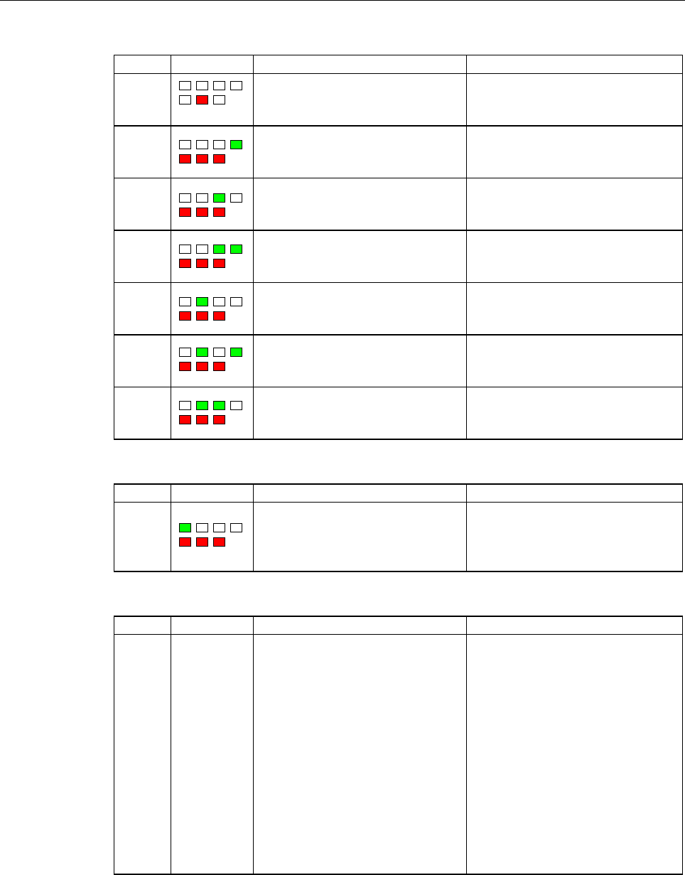
2.ALARM NUMBERS AND BRIEF DESCRIPTIONS TROUBLESHOOTING B-65395EN/01
- 200 -
No. LED display Description Countermeasure
−
An error was detected in the control
circuit.
Turn the power off then back on. If this
alarm recurs, replace the servo
amplifier module.
−
A alarm for the servo amplifier
module is issued. (General illegal
instruction)
Turn the power off then back on. If this
alarm recurs, replace the servo
amplifier module.
−
A alarm for the servo amplifier
module is issued. (Slot illegal
instruction)
Turn the power off then back on. If this
alarm recurs, replace the servo
amplifier module.
−
A alarm for the servo amplifier
module is issued. (CPU address
error)
Turn the power off then back on. If this
alarm recurs, replace the servo
amplifier module.
−
A alarm for the servo amplifier
module is issued. (DTC address
error)
Turn the power off then back on. If this
alarm recurs, replace the servo
amplifier module.
−
Stuck overflow occurred.
Turn the power off then back on. If this
alarm recurs, replace the servo
amplifier module.
−
Stuck underflow occurred.
Turn the power off then back on. If this
alarm recurs, replace the servo
amplifier module.
I/O link alarm
No. LED display Description Countermeasure
−
A FANUC I/O Link error occurred.
Some unit connected to the line was
turned off.
Turn off the power to all units
connected to the line. Then, turn on
the slave devices, followed by the
master device.
No LED display
No. LED display Description Countermeasure
−
No indicators
lit
The control circuit is not operating
normally.
(1) Check the 24-VDC control supply
voltage. If the voltage is low,
increase the voltage to an
appropriate level.
(2) Check whether a fuse in the
servo amplifier module has
blown.
If a blown fuse is found, replace
it, following the procedure
described in Part IV
"Maintenance of Servo Amplifier
Unit."
If (1) and (2) are not the cause,
replace the servo amplifier.
Contents Summary of SERVO AMPLIFIER Beta i series Maintenance manual
- Page 1FANUC AC SERVO MOTOR #*s series FANUC AC SPINDLE MOTOR #* series FANUC SERVO AMPLIF IER #* series I/O Link Option MAINTENANCE MANUAL B-65395EN/01
- Page 2Ȧ No part of this manual may be reproduced in any form. Ȧ All specifications and designs are subject to change without notice. In this manual we have tried as much as possible to describe all the various matters. However, we cannot describe all the matters which must not be done, or which cannot be
- Page 3B-65395EN/01 SAFETY PRECAUTIONS SAFETY PRECAUTIONS The "Safety Precautions" section describes the safety precautions relating to the use of FANUC servo motors and servo amplifiers (βi SVM). Users of any servo motor or amplifier model are requested to read the "Safety Precautions" carefully before us
- Page 4SAFETY PRECAUTIONS B-65395EN/01 1.1 DEFINITION OF WARNING, CAUTION, AND NOTE This manual includes safety precautions for protecting the user and preventing damage to the machine. Precautions are classified into Warning and Caution according to their bearing on safety. Also, supplementary information
- Page 5B-65395EN/01 SAFETY PRECAUTIONS 1.2 FANUC AC SERVO MOTOR βis series 1.2.1 Warning WARNING • Be safely dressed when handling a motor. Wear safety shoes or gloves when handling a motor as you may get hurt on any edge or protrusion on it or electric shocks. • Use a crane or lift to move a motor from on
- Page 6SAFETY PRECAUTIONS B-65395EN/01 WARNING • Do not supply the power to the motor while any terminal is exposed. A failure to observe this caution is very dangerous because you may get electric shocks if your body or any conductive stuff touches an exposed terminal. • Do not bring any dangerous stuff n
- Page 7B-65395EN/01 SAFETY PRECAUTIONS • When designing and assembling a machine tool, make it compliant with EN60204-1. To ensure the safety of the machine tool and satisfy European standards, when designing and assembling a machine tool, make it compliant with EN60204-1. For details of the machine tool,
- Page 8SAFETY PRECAUTIONS B-65395EN/01 1.2.2 Caution CAUTION • FANUC motors are designed for use with machines. Do not use them for any other purpose. If a FANUC motor is used for an unintended purpose, it may cause an unexpected symptom or trouble. If you want to use a motor for an unintended purpose, pre
- Page 9B-65395EN/01 SAFETY PRECAUTIONS 1.2.3 Note NOTE • Do not step or sit on a motor. If you step or sit on a motor, it may get deformed or broken. Do not put a motor on another unless they are in packages. • When storing a motor, put it in a dry (non-condensing) place at room temperature (0 to 40°C). If
- Page 10SAFETY PRECAUTIONS B-65395EN/01 NOTE • Use a motor under an appropriate environmental condition. Using a motor in an adverse environment may cause a failure or trouble in it. Refer to their respective Descriptions for details of the operating and environmental conditions for motors. • Do not apply a
- Page 11B-65395EN/01 SAFETY PRECAUTIONS 1.3 FANUC SERVO AMPLIFIER βi series 1.3.1 Warnings and Cautions Relating to Mounting 1.3.1.1 Warning WARNING • Check the specification code of the amplifier. Check that the delivered amplifier is as originally ordered. • Mount a ground fault interrupter. To guard agai
- Page 12SAFETY PRECAUTIONS B-65395EN/01 WARNING • Close the amplifier cover after completing the wiring. Leaving the cover open presents a danger of electric shock. • Do not disassemble the amplifier. • Ensure that the cables used for the power supply lines and power lines are of the appropriate diameter an
- Page 13B-65395EN/01 SAFETY PRECAUTIONS 1.3.1.2 Caution CAUTION • Do not step or sit on the amplifier. Also, do not stack unpacked amplifiers on top of each other. • Use the amplifier in an appropriate environment. See the allowable ambient temperatures and other requirements, given in the corresponding Des
- Page 14SAFETY PRECAUTIONS B-65395EN/01 CAUTION • Check that the amplifier is securely mounted in the power magnetics cabinet. If any clearance is left between the power magnetics cabinet and the surface on which the amplifier is mounted, dust entering the gap may build up and prevent the normal operation o
- Page 15B-65395EN/01 SAFETY PRECAUTIONS 1.3.1.3 Note NOTE • Keep the nameplate clearly visible. • Keep the legend on the nameplate clearly visible. • After unpacking the amplifier, carefully check for any damage. • Mount the amplifier in a location where it can be easily accessed periodic inspection and dai
- Page 16SAFETY PRECAUTIONS B-65395EN/01 1.3.2 Warnings and Cautions Relating to a Pilot Run 1.3.2.1 Warning WARNING • Before turning on the power, check that the cables connected to the power magnetics cabinet and amplifier, as well as the power lines and power supply lines, are securely connected. Also, ch
- Page 17B-65395EN/01 SAFETY PRECAUTIONS WARNING • Before opening a door or protective cover of a machine to enable adjustment of the machine, first place the machine in the emergency stop state and check that the motor has stopped. s-15
- Page 18SAFETY PRECAUTIONS B-65395EN/01 1.3.2.2 Caution CAUTION • Note whether an alarm status relative to the amplifier is displayed at power-up or during operation. If an alarm is displayed, take appropriate action as explained in this manual. If the work to be done requires that the door of the power mag
- Page 19B-65395EN/01 SAFETY PRECAUTIONS 1.3.3 Warnings and Cautions Relating to Maintenance 1.3.3.1 Warning WARNING • Read this manual carefully and ensure that you are totally familiar with its contents. This manual describes daily maintenance and the procedures to be followed in the event of an alarm bein
- Page 20SAFETY PRECAUTIONS B-65395EN/01 WARNING • Notes on replacing the battery of the absolute Pulsecoder Replace the battery only while the power is on. If the battery is replaced while the power is turned off, the stored absolute positioning data will be lost. A battery may be mounted on the servo ampli
- Page 21B-65395EN/01 SAFETY PRECAUTIONS 1.3.3.2 Caution CAUTION • Ensure that all required components are mounted. When replacing a component or PC board, check that all components, including the snubber capacitor, are correctly mounted. If the snubber capacitor is not mounted, for example, the IPM will be
- Page 22SAFETY PRECAUTIONS B-65395EN/01 1.3.3.3 Note NOTE • Ensure that the battery connector is correctly inserted. If the power is shut off while the battery connector is not connected correctly, the absolute position data for the machine will be lost. • Store the manuals in a safe place. The manuals shou
- Page 23B-65395EN/01 PREFACE PREFACE Organization of this manual This manual describes information necessary to maintain FANUC SERVO AMPLIFIER βi series products, such as a βi SVM and FANUC SERVO MOTOR βis series products. Parts I, II, III and IV explain the start-up procedure, operation, troubleshooting, a
- Page 24
- Page 25B-65395EN/01 TABLE OF CONTENTS TABLE OF CONTENTS SAFETY PRECAUTIONS............................................................................s-1 PREFACE ....................................................................................................p-1 I. START-UP PROCEDURE 1 OVERVIEW ........
- Page 26TABLE OF CONTENTS B-65395EN/01 2 SIGNAL DESCRIPTIONS ..................................................................... 37 2.1 DO/DO SIGNALS ........................................................................................ 38 2.1.1 Peripheral Equipment Control Interface....................
- Page 27B-65395EN/01 TABLE OF CONTENTS 3.4.6.2 System configuration ......................................................................................... 86 3.4.6.3 Peripheral equipment control command format................................................. 87 3.4.6.4 Command timing chart ..............
- Page 28TABLE OF CONTENTS B-65395EN/01 3.8.2 Details of Function ...............................................................................................109 3.8.3 DI/DO Signals ......................................................................................................110 3.8.4 Parameter...
- Page 29B-65395EN/01 TABLE OF CONTENTS 4.5.3 Operation Procedure.............................................................................................168 5 EXTERNAL PULSE INPUT FUNCTION ............................................. 169 5.1 OVERIVIEW ...................................................
- Page 30TABLE OF CONTENTS B-65395EN/01 1.2.1 For Fan Motors for Internal Agitation for SVM1-4i and SVM1-20i ...................215 1.2.2 For Fan Motors for Internal Agitation for SVM1-40i and SVM1-80i .................216 1.2.3 External-Fan Motor .............................................................
- Page 31B-65395EN/01 TABLE OF CONTENTS D POWER MATE CNC MANAGER FUNCTIONS .................................. 292 D.1 POWER MATE CNC MANAGER FUNCTIONS (Series 16, 18, 21, Power Mate) ................................................................ 293 D.1.1 Overview ..........................................
- Page 32
- Page 33I. START-UP PROCEDUR
- Page 34
- Page 35B-65395EN/01 START-UP PROCEDURE 1.OVERVIEW 1 OVERVIEW This part describes the units and components of the FANUC servo amplifier. It also explains the following information necessary to start up the servo amplifier: • Configurations • Start-up procedure • Confirmation of the operation • Periodic main
- Page 362.CONFIGURATIONS START-UP PROCEDURE B-65395EN/01 2 CONFIGURATIONS -4-
- Page 37B-65395EN/01 START-UP PROCEDURE 2.CONFIGURATIONS 2.1 CONFIGURATIONS A system using FANUC servo amplifier βi series SVMs consists of the following units and parts: (1) Servo amplifier module (SVM) (basic) (2) AC line filter (basic) (3) Connectors (for connecting cables) (basic) (4) Fuses (option) (5)
- Page 382.CONFIGURATIONS START-UP PROCEDURE B-65395EN/01 2.2 MAJOR COMPONENTS 2.2.1 Servo Amplifier Modules (1) Servo amplifier module (SVM1) Wiring board Printed circuit board Model Order specification Unit specification specification specification SVM1-4i A06B-6132-H001 A06B-6132-C001 A20B-2101-0090 SVM1-
- Page 39B-65395EN/01 START-UP PROCEDURE 3.START-UP PROCEDURE 3 START-UP PROCEDURE -7-
- Page 403.START-UP PROCEDURE START-UP PROCEDURE B-65395EN/01 3.1 START-UP PROCEDURE (OVERVIEW) Make sure that the specifications of the CNC, servo motors, servo amplifiers, and other units you received are exactly what you ordered, and these units are connected correctly. Then, turn on the power. (1) Before
- Page 41B-65395EN/01 START-UP PROCEDURE 3.START-UP PROCEDURE 3.2 CONNECTING THE POWER 3.2.1 Checking the Voltage and Capacity of the Power Before connecting the power, you should measure the AC power voltage. Table 3.2.1(a) Action for the AC power (200-V input type) Permissible voltage Nominal Action fluctu
- Page 423.START-UP PROCEDURE START-UP PROCEDURE B-65395EN/01 3.3 INITIALIZING PARAMETERS (SWITCHES AND DUMMY CONNECTORS) SVM1-4i, SVM1-20i • When no regenerative resistor is used Connect connector CXA20 by using a dummy connector. See FANUC SERVO AMPLIFIER βi series DESCRIPTIONS (B-65322EN). SVM1-40i, SVM1-
- Page 43B-65395EN/01 START-UP PROCEDURE 3.START-UP PROCEDURE 3.4 PARAMETER INITIALIZATION (1) Preparation prior to servo parameter initialization Before servo parameter initialization, check the following: <1> Servo motor model (Example: β8/3000is) <2> Amount of travel per motor rotation (Example: 10 mm/mot
- Page 443.START-UP PROCEDURE START-UP PROCEDURE B-65395EN/01 <5> Set a motor type number. In parameter No. 125, set the motor type number of the servo motor to be used. SVM1-4i Motor model β0.2/5000is β0.3/5000is Motor 0111 0112 specification Motor type number 260 261 SVM1-20i Motor model α1/5000i β2/4000is
- Page 45B-65395EN/01 START-UP PROCEDURE 3.START-UP PROCEDURE <7> Set the number of pulses per revolution The number of pulses per revolution is calculated with reduction ratios or leads of the ball screws and detection unit. (Number of pulses per motor revolution) = (amount of travel per motor revolution) /
- Page 463.START-UP PROCEDURE START-UP PROCEDURE B-65395EN/01 <10>Turn off/on both CNC and servo amplifier module and servo parameter initialization is finished. This completes servo parameter initialization. <11>If you use αi pulse coder as an absolute pulse coder, some procedures described below are needed
- Page 47B-65395EN/01 START-UP PROCEDURE 4.CONFIRMATION OF THE OPERATION 4 CONFIRMATION OF THE OPERATION - 15 -
- Page 484.CONFIRMATION OF THE OPERATION START-UP PROCEDURE B-65395EN/01 4.1 CHECK PROCEDURE 1. Turn on the power. When the LED indicates data other than or Refer to the explanation of troubleshooting in Part III. 2. The LED indicates 3. The emergency stop state is released. The LED does not indicate Check t
- Page 49B-65395EN/01 START-UP PROCEDURE 4.CONFIRMATION OF THE OPERATION Table 4.1 LED Indications and Meanings LED indication State Description This indicates that control power (+24 Servo amplifier VDC) is supplied. No alarm is issued, but module not ready the motor is not activated. Servo amplifier This i
- Page 504.CONFIRMATION OF THE OPERATION START-UP PROCEDURE B-65395EN/01 LED LED 4/20A 40/80A - 18 -
- Page 51B-65395EN/01 START-UP PROCEDURE 5.PERIODIC MAINTENANCE OF SERVO AMPLIFIER 5 PERIODIC MAINTENANCE OF SERVO AMPLIFIER - 19 -
- Page 525.PERIODIC MAINTENANCE OF SERVO AMPLIFIER START-UP PROCEDURE B-65395EN/01 5.1 BATTERY FOR THE ABSOLUTE PULSECODER The battery unit for the absolute Pulsecoder can be connected using [Connection scheme 1] and [Connection scheme 2] explained below. [Connection scheme 1] Supplying power from one batter
- Page 53B-65395EN/01 START-UP PROCEDURE 5.PERIODIC MAINTENANCE OF SERVO AMPLIFIER WARNING 1 Do not connect more than one battery to the same BAT (B3) line. If the output voltage is different between the batteries, they may be short-circuited, resulting in the batteries becoming very hot. 2 Install the batte
- Page 545.PERIODIC MAINTENANCE OF SERVO AMPLIFIER START-UP PROCEDURE B-65395EN/01 [Connection scheme 2] Incorporating each SVM with batteries SVM SVM Battery case A06B-6093-K002 Battery A06B-6093-K001 CX5X CX5X Battery case A06B-6093-K002 Battery A06B-6093-K001 • If a low battery voltage or a battery voltag
- Page 55B-65395EN/01 START-UP PROCEDURE 5.PERIODIC MAINTENANCE OF SERVO AMPLIFIER WARNING 1 When using the built-in batteries (A06B-6093-K001), do not connect them to the BAT (B3) of connector CXA19A/CXA19B. The output voltages from different SVM batteries may be short-circuited, resulting in the batteries
- Page 565.PERIODIC MAINTENANCE OF SERVO AMPLIFIER START-UP PROCEDURE B-65395EN/01 ⋅ SVM1-40i, SVM1-80i (1) Install the battery in the SVM. (2) Install the battery cover. (3) Attach the battery connector to CX5X of the SVM. SVM Inserting direction Cable side Red: +6 V Connector Black: 0 V Battery CX5X Batter
- Page 57B-65395EN/01 START-UP PROCEDURE 5.PERIODIC MAINTENANCE OF SERVO AMPLIFIER [Caution No. 1 for battery replacement] The Pulsecoder of the β series servo motors and some of the βiS series servo motors (β0.2/5000iS to β0.3/5000iS) does not include a backup capacitor as standard. To keep the absolute pos
- Page 585.PERIODIC MAINTENANCE OF SERVO AMPLIFIER START-UP PROCEDURE B-65395EN/01 [Caution No. 2 for battery replacement] If an excessive strain is applied to a connector when it is inserted or removed, a poor contact may result. When inserting and removing the battery connector, therefore, be careful not t
- Page 59B-65395EN/01 START-UP PROCEDURE 5.PERIODIC MAINTENANCE OF SERVO AMPLIFIER (2) Detaching the connector Hold both the sides of the cable insulator and the cable, and pull them horizontally. <1> Pull out the cable side while raising it slightly. <2> 10 degrees or less Here, the angle of the cable to th
- Page 605.PERIODIC MAINTENANCE OF SERVO AMPLIFIER START-UP PROCEDURE B-65395EN/01 5.2 PERIODIC MAINTENANCE OF SERVO AMPLIFIER To use the servo amplifier for a long time and keep its high performance and reliability, you should perform maintenance and inspection on it routinely. Inspection Inspection Inspect
- Page 61B-65395EN/01 START-UP PROCEDURE 5.PERIODIC MAINTENANCE OF SERVO AMPLIFIER Specification number of fan unit - SVM Fan for circulating the inside air Fan for cooling external heat sink fins SVM name Fan unit (*1) Fan motor Fan unit (*1) Fan motor SVM1-4i - A90L-0001-0423#50 - - SVM1-20i SVM1-40i A06B-
- Page 62
- Page 63II. HANDLIN
- Page 64
- Page 65B-65395EN/01 HANDLING 1.OVERVIEW 1 OVERVIEW - 33 -
- Page 661.OVERVIEW HANDLING B-65395EN/01 1.1 SERVO AMPLIFIER MODULE INTERFACE The servo amplifier module is connected to a host unit such as a CNC via 128 DI and 128 DO points of the FANUC I/O Link. The ladder program on the host unit sends move commands to the servo amplifier module and monitors its status
- Page 67B-65395EN/01 HANDLING 1.OVERVIEW 1.3 INTERFACE Interfaces are used to transfer data to and from the servo amplifier module. Essentially, there are two operation modes: Peripheral equipment control interface and direct command interface. The mode to be used is selected by the DRC signal in the signal
- Page 681.OVERVIEW HANDLING B-65395EN/01 DRC signal switching must be performed during a reset state. Signal switching causes the meaning of a signal in use to be changed. Be careful when a command is being issued or axis movement is occurring, as signal switching may result in unexpected behavior. Once the
- Page 69B-65395EN/01 HANDLING 2.SIGNAL DESCRIPTIONS 2 SIGNAL DESCRIPTIONS - 37 -
- Page 702.SIGNAL DESCRIPTIONS HANDLING B-65395EN/01 2.1 DO/DO SIGNALS A host unit such as a CNC is connected to the servo amplifier module via 128 DI and 128 DO points of the FANUC I/O Link. CAUTION I/O link interface signal assignment differs between the peripheral equipment control and direct command inte
- Page 71B-65395EN/01 HANDLING 2.SIGNAL DESCRIPTIONS Servo amplifier module → CNC (host) (DRC=0) 7 6 5 4 3 2 1 0 Xx+0 OPC4 OPC3 OPC2 OPC1 INPX SUPX IPLX DEN2 Xx+1 OP SA STL UCPC2 OPTENB ZRFX DRCO ABSWT Xx+2 MA AL DSP2 DSP1 DSALO TRQM RST ZPX Xx+3 Xx+4 Response data Xx+5 Xx+6 Xx+7 SVERX PSG2 PSG1 MVX APBAL MV
- Page 722.SIGNAL DESCRIPTIONS HANDLING B-65395EN/01 2.1.2 Direct Command Interface Locations Yy+0 to Yy+3 are allocated as the DO signal area, while locations Xx+0 to Xx+3 are allocated as the DI signal area. To control the servo amplifier unit, turn on or off directly those signals that are assigned to the
- Page 73B-65395EN/01 HANDLING 2.SIGNAL DESCRIPTIONS Servo amplifier module → CNC (host) (DRC=1) 7 6 5 4 3 2 1 0 Xx+0 INPX SUPX IPLX DEN2 Xx+1 OP SA STL OPTENB ZRFX DRCO WAT Xx+2 MA AL TRQM RST ZPX Xx+3 INPFO SVERX PSG2 PSG1 MVX APBAL MVDX Xx+4 EBSY EOSTB ECF USR1 EOPC DAL ECONT Xx+5 Direct command (function
- Page 742.SIGNAL DESCRIPTIONS HANDLING B-65395EN/01 2.2 SIGNALS (LISTED IN GROUPS) * The following lists not only signals transferred via the I/O link interface but also direct input/output signals such as *ESP, *-OT, *+OT, *RILK, *DEC, and HDI. * Each listed address is based on the I/O link assignment addr
- Page 75B-65395EN/01 HANDLING 2.SIGNAL DESCRIPTIONS Address Reference Group Signal name Symbol Peripheral Direct command item equipment Unclamp command signal UCPC2 Xx+1#4 -- 2.3.11 11 Clamp/unclamp state output signal UCPS2 Yy+0#6 -- 2.3.11 12 Servo-off signal SVFX Yy+1#2 2.3.12 OPC1, OPC2, Operation compl
- Page 762.SIGNAL DESCRIPTIONS HANDLING B-65395EN/01 2.3 SIGNAL DETAILS 2.3.1 Preparation Completion (1) Preparation completion signal MA [Classification] Input signal
- Page 77B-65395EN/01 HANDLING 2.SIGNAL DESCRIPTIONS 2.3.2 Reset and Emergency Stop (1) Emergency stop signal *ESP [Classification] Output signal
- Page 782.SIGNAL DESCRIPTIONS HANDLING B-65395EN/01 2.3.3 Alarm (1) Alarm signal AL [Classification] Input signal
- Page 79B-65395EN/01 HANDLING 2.SIGNAL DESCRIPTIONS 2.3.4 Mode Selection (1) Mode selection signal MD1, MD2, MD4 [Classification] Output signal
- Page 802.SIGNAL DESCRIPTIONS HANDLING B-65395EN/01 2.3.6 Status Signals (1) Remaining travel in-range signal DEN2 [Classification] Input signal
- Page 81B-65395EN/01 HANDLING 2.SIGNAL DESCRIPTIONS (3) Acceleration/deceleration pulse signal SUPX [Classification] Input signal
- Page 822.SIGNAL DESCRIPTIONS HANDLING B-65395EN/01 The signal becomes 0 when: 1. Controlled axis movement ends, and the controlled axis enters the in-position state. 2. Bit 7 (SVFP) of parameter No. 010 is set to 1 to perform follow-up in clamp processing or servo-off state, and the servo position deviatio
- Page 83B-65395EN/01 HANDLING 2.SIGNAL DESCRIPTIONS NOTE 1 The servo amplifier module outputs the PSG1 and PSG2 signals even during follow-up, provided the necessary condition is satisfied. 2 When bit 1 (PSSV) of parameter No. 007 is "1", input is accomplished with the position (actual motor position) with
- Page 842.SIGNAL DESCRIPTIONS HANDLING B-65395EN/01 2.3.7 Feedrate (1) Override signals *OV1 to *OV8 [Classification] Output signal
- Page 85B-65395EN/01 HANDLING 2.SIGNAL DESCRIPTIONS (3) Rapid traverse override signals ROV1 and ROV2 [Classification] Output signal
- Page 862.SIGNAL DESCRIPTIONS HANDLING B-65395EN/01 2.3.8 Interlock (1) Interlock signal *ILK [Classification] Output signal
- Page 87B-65395EN/01 HANDLING 2.SIGNAL DESCRIPTIONS 2.3.10 Automatic Operation (1) Automatic operation start signal ST [Classification] Output signal
- Page 882.SIGNAL DESCRIPTIONS HANDLING B-65395EN/01 2.3.11 Clamp and Unclamp (for the Peripheral Equipment Control Interface Only) NOTE When the signal described below is used, the external pulse input function cannot be used. (1) Unclamp command signal UCPC2 [Classification] Input signal
- Page 89B-65395EN/01 HANDLING 2.SIGNAL DESCRIPTIONS 2.3.12 Servo-off (1) Servo-off command signal SVFX [Classification] Output signal
- Page 902.SIGNAL DESCRIPTIONS HANDLING B-65395EN/01 2.3.13 Peripheral Equipment Control Function Code and Related Information (1) Operation completion signals OPC1, OPC2, OPC3, and OPC4 [Classification] Input signal
- Page 91B-65395EN/01 HANDLING 2.SIGNAL DESCRIPTIONS (3) Command data 1 [Classification] Output signal
- Page 922.SIGNAL DESCRIPTIONS HANDLING B-65395EN/01 CAUTION 1 The purpose of this data, when used by the host, is limited to display on the host. This data consists of 32 bits of DI signals; the bits are not updated at a time, but are updated on a bit-by-bit basis. So, if this data is being updated when coo
- Page 93B-65395EN/01 HANDLING 2.SIGNAL DESCRIPTIONS (6) Response data check signals DSP1 and DSP2 [Classification] Input signal
- Page 942.SIGNAL DESCRIPTIONS HANDLING B-65395EN/01 (10) Alarm output state check signal DSALO [Classification] Input signal
- Page 95B-65395EN/01 HANDLING 2.SIGNAL DESCRIPTIONS (4) Command data [Classification] Output signal
- Page 962.SIGNAL DESCRIPTIONS HANDLING B-65395EN/01 (7) Response data readable signal EOSTB [Classification] Input signal
- Page 97B-65395EN/01 HANDLING 2.SIGNAL DESCRIPTIONS (11) Response data continuation notification signal ECONT [Classification] Input signal
- Page 982.SIGNAL DESCRIPTIONS HANDLING B-65395EN/01 (15) Wait completion signal WFN [Classification] Output signal
- Page 99B-65395EN/01 HANDLING 2.SIGNAL DESCRIPTIONS (18) Interface switch signal DRC [Classification] Output signal
- Page 1002.SIGNAL DESCRIPTIONS HANDLING B-65395EN/01 2.3.15 Direct Input Signals NOTE The following signals are not host-to-servo amplifier module FANUC I/O Link interface signals. (1) Emergency stop signal *ESP [Classification] Servo amplifier module direct input signal [Function] The host stops the servo a
- Page 101B-65395EN/01 HANDLING 2.SIGNAL DESCRIPTIONS (4) Deceleration signal for reference position return *DEC [Classification] Servo amplifier module direct input signal [Function] The host decelerates feed operation based on a reference position return command. [Operation] The servo amplifier module decel
- Page 1022.SIGNAL DESCRIPTIONS HANDLING B-65395EN/01 NOTE 1 To perform positioning for the skip function, bit 0 (HENB) of parameter No. 017 must be set to "1" (use the skip function). 2 It is possible to specify, using an appropriate parameter, whether to retain the previous skip measurement data or record t
- Page 103B-65395EN/01 HANDLING 3.PERIPHERAL EQUIPMENT CONTROL 3 PERIPHERAL EQUIPMENT CONTROL - 71 -
- Page 1043.PERIPHERAL EQUIPMENT CONTROL HANDLING B-65395EN/01 3.1 COMMAND FORMAT FOR PERIPHERAL EQUIPMENT CONTROL The servo amplifier module receives a command, issued in the specified format, from the host, then executes a sequence of operations for performing peripheral equipment control. When a command fo
- Page 105B-65395EN/01 HANDLING 3.PERIPHERAL EQUIPMENT CONTROL 3.2 PERIPHERAL EQUIPMENT CONTROL PROCEDURE 3.2.1 Specifying Operation Using a Function Code In peripheral equipment control, the host sets a function code, command data 1, and command data 2, then turns the automatic operation start signal (ST) in
- Page 1063.PERIPHERAL EQUIPMENT CONTROL HANDLING B-65395EN/01 3.3 FUNCTION CODES 3.3.1 Function Codes Command data 1 Command data 2 Start Function code Mode Remarks 4 bits 4 bytes signal 0 : Jog operation JOG +X/-X (Note 1) 1: Automatic operation (shortcut rotation) Set an amount of travel per 2: Automatic o
- Page 107B-65395EN/01 HANDLING 3.PERIPHERAL EQUIPMENT CONTROL NOTE 1 Besides function code 0, jog operation can also be performed with 1, 10, and 15. 2 If the remaining distance to the next point is shorter than the required deceleration distance for stopping at that point when the feed axis and direction se
- Page 1083.PERIPHERAL EQUIPMENT CONTROL HANDLING B-65395EN/01 3.4 DETAILS OF FUNCTION CODES 3.4.1 ATC/Turret Control Host NC Servo amplifier module operation state CNC PMC (1) O 0001 Jog or Auto mode : Start enabled state T ×× Function code = 2 Processi ng by PMC Command data 1 (feed type code) Command data
- Page 109B-65395EN/01 HANDLING 3.PERIPHERAL EQUIPMENT CONTROL (3) Upon completion of the movement, the servo amplifier module returns the operation completion signal OPC 3 to the host NC, and also outputs the clamp command signal. (4) When clamp completion notification is sent from the host NC, the servo amp
- Page 1103.PERIPHERAL EQUIPMENT CONTROL HANDLING B-65395EN/01 3.4.2 Point Positioning Control Host NC Servo amplifier module operation state CNC PMC (1) Auto mode Start enabled state Function code = 3 Processing by PMC Command data 1 (feed type code) Command data 2 (point number) ST signal (2) Operation comp
- Page 111B-65395EN/01 HANDLING 3.PERIPHERAL EQUIPMENT CONTROL (4) When clamp completion notification is sent from the host NC, the servo amplifier module returns response data (point number or coordinates) and the operation completion signal OPC 4, and is placed in the start enabled state. (5) If an alarm is
- Page 1123.PERIPHERAL EQUIPMENT CONTROL HANDLING B-65395EN/01 3.4.3 Reference Position Return Host NC Servo amplifier module operation state CNC PMC (1) Jog mode Start enabled state Function code = 4 Processing by PMC Command data 1 (reference position number/reference position setting) ST signal, +X/-X sign
- Page 113B-65395EN/01 HANDLING 3.PERIPHERAL EQUIPMENT CONTROL (5) If an alarm is issued while the servo amplifier module is executing a reference position return operation, the AL signal is output. So, the PMC on the host NC is to perform processing such as alarm indication. In this case, the number of alarm
- Page 1143.PERIPHERAL EQUIPMENT CONTROL HANDLING B-65395EN/01 3.4.4 Reference Position Setting (when the Reference Position External Setting Function is Used) Host NC Servo amplifier module operation state CNC PMC Positioning to a reference position Jog mode Emergency stop release state Start of the referenc
- Page 115B-65395EN/01 HANDLING 3.PERIPHERAL EQUIPMENT CONTROL (4) If an alarm is issued while the servo amplifier module is executing reference position setting, the AL signal is output. So, the PMC on the host NC is to perform processing such as alarm indication. In this case, the number of alarms and alarm
- Page 1163.PERIPHERAL EQUIPMENT CONTROL HANDLING B-65395EN/01 3.4.5 Positioning Control (Absolute/Incremental Specification, for Skip Function) Host NC Servo amplifier module operation state CNC PMC (1) O0001 Auto mode : Start enabled state T xx Function code = 5, 6, 8 Processing by PMC Command data 1 (feedr
- Page 117B-65395EN/01 HANDLING 3.PERIPHERAL EQUIPMENT CONTROL (3) After the end of movement (for the skip function, after the input of HDI), the servo amplifier module returns the operation completion signal OPC3 to the host NC, and at the same time, outputs a clamp command signal to the host NC. (4) When cl
- Page 1183.PERIPHERAL EQUIPMENT CONTROL HANDLING B-65395EN/01 3.4.6 Speed Control 3.4.6.1 Overview The speed control function executes speed control by specifying a speed value as command data. Moreover, acceleration/deceleration is applied using a time constant (parameter No. 135) dedicated to speed control
- Page 119B-65395EN/01 HANDLING 3.PERIPHERAL EQUIPMENT CONTROL 3.4.6.3 Peripheral equipment control command format A speed command value is specified using the following command: Command (host → servo amplifier module) 7 6 5 4 3 2 1 0 BIT Yy+2 Function code Command data 1 Yy+3 Yy+4 Command data 2 Yy+5 Yy+6 Mo
- Page 1203.PERIPHERAL EQUIPMENT CONTROL HANDLING B-65395EN/01 Yy+3 DC Yy+4 05 Yy+5 39 Yy+6 0E NOTE 1 The maximum speed of the motor depends on the motor used. 2 For type B, even if torque limit is not performed (torque limit of 100%), specify 0 or 7282 for the torque limit. 3 For type B, to change only the t
- Page 121B-65395EN/01 HANDLING 3.PERIPHERAL EQUIPMENT CONTROL 3.4.6.4 Command timing chart (1) Start of speed control <1> Type A Speed control is activated according to the timing chart shown below after the setting of function code = 7, command data 1 = 0, command data 2 = speed command value. ST OPC1 Drivi
- Page 1223.PERIPHERAL EQUIPMENT CONTROL HANDLING B-65395EN/01 (2) Speed change with speed control <1> Type A A speed change based on speed control is activated according to the timing chart shown below after the setting of function code = 7, command data 1 = 0, command data 2 = new speed command value. ST OP
- Page 123B-65395EN/01 HANDLING 3.PERIPHERAL EQUIPMENT CONTROL (3) Termination of speed control <1> Type A Speed control is terminated according to the timing chart shown below after the setting of function code = 7 and command data 1 = 1. ST OPC1 Driving of the motor (Termination) OPC4 TRQM <2> Type B Speed
- Page 1243.PERIPHERAL EQUIPMENT CONTROL HANDLING B-65395EN/01 3.4.6.5 Parameter No #7 #6 #5 #4 #3 #2 #1 #0 000 ROAX ROTX [Size] 1 byte (bit type) [Standard setting value] 0 ROTX Specifies whether the controlled axis is a linear or rotation axis, as follows: 0 : Linear axis 1 : Rotation axis * To perform spee
- Page 125B-65395EN/01 HANDLING 3.PERIPHERAL EQUIPMENT CONTROL No 100 Load inertia ratio (LDINT) [Size] 2-byte [Valid data range] 0 to 1024 Set the ratio of the machine load inertia to the motor inertia, using a value obtained from the formula below as a guideline. Load inertia ratio = (machine load inertia/m
- Page 1263.PERIPHERAL EQUIPMENT CONTROL HANDLING B-65395EN/01 No 135 Linear acceleration/deceleration time constant for speed control [Size] 2-byte [Unit of data] ms [Valid data range] 8 to 4000 Specify a time required until 4000 min-1 is reached. Example) When a speed command value of 2000 min-1 is specifie
- Page 127B-65395EN/01 HANDLING 3.PERIPHERAL EQUIPMENT CONTROL 3.4.6.8 Others (1) To exercise speed control, the parameters below usually need to be modified. Do not modify parameters other than the parameters below. No.000 (bit 1) : Set this bit to 1 (rotation axis specification). No.000 (bit 7) : Set this b
- Page 1283.PERIPHERAL EQUIPMENT CONTROL HANDLING B-65395EN/01 3.4.7 Coordinate System Setting Host NC Servo amplifier module operation state CNC PMC Start of coordinate Auto mode (1) system setting Start enabled state Processing Function code = 10 by PMC Command data 1 (coordinate system setting, magazine nu
- Page 129B-65395EN/01 HANDLING 3.PERIPHERAL EQUIPMENT CONTROL 3.4.8 Rewriting of Parameters 3.4.8.1 Overview When using the peripheral equipment control parameter rewrite function, specify 12 as function code, a data size as command data 1, a parameter number and parameter value as command data 2, and start
- Page 1303.PERIPHERAL EQUIPMENT CONTROL HANDLING B-65395EN/01 3.4.8.3 Peripheral equipment control command format A parameter to be rewritten is specified using the following command: Command (host → servo amplifier module) 7 6 5 4 3 2 1 0 Yy+2 Function code Command data 1 Yy+3 Yy+4 Command data 2 Yy+5 Yy+6
- Page 131B-65395EN/01 HANDLING 3.PERIPHERAL EQUIPMENT CONTROL 3.4.8.4 Command timing chart ST OPC1 Rewriting being performed OPC4 3.4.8.5 Alarm No. LED indication Description Action Command data 1 or the instruction Check the specified value of command 250 command is invalid. data 1 of a function code comman
- Page 1323.PERIPHERAL EQUIPMENT CONTROL HANDLING B-65395EN/01 3.4.9 Control of the Point Data External Setting Function Host NC Servo amplifier module operation state CNC PMC Jog mode Start enabled state Start of data setting Processing Function code = 14 (point data setting) (1) by PMC Command data 1 (point
- Page 133B-65395EN/01 HANDLING 3.PERIPHERAL EQUIPMENT CONTROL 3.4.10 Teaching-based Data Setting Control Host NC Servo amplifier module operation state CNC PMC Function code = 15 Jog mode (1) Start enabled state +X -X A position to be set is indexed. Start of data setting (2) Processing by PMC Command data 2
- Page 1343.PERIPHERAL EQUIPMENT CONTROL HANDLING B-65395EN/01 3.5 REFERENCE POSITION RETURN FUNCTION WITH DOGS 3.5.1 Explanation of Function This function moves the machine movable part automatically or manually in a specified direction to return to a reference position. This method of reference position ret
- Page 135B-65395EN/01 HANDLING 3.PERIPHERAL EQUIPMENT CONTROL A gradual stop occurs if a mode other than the jog feed mode is selected or the feed axis direction command signal (+X or -X) is turned off during reference position return. Reference position return must start at a point sufficiently away from a
- Page 1363.PERIPHERAL EQUIPMENT CONTROL HANDLING B-65395EN/01 (i) LDW: Deceleration dog width (user unit) LDW > (VR((TR/2)+11+TS)+4VL×TS)/60000 VR:Rapid traverse rate (user unit/min) TR:Rapid traverse time constant (msec) TS:Servo time constant (msec) VL:Feedrate after deceleration (user unit/min) (ii) LDA:D
- Page 137B-65395EN/01 HANDLING 3.PERIPHERAL EQUIPMENT CONTROL 3.5.2 Parameter No #7 #6 #5 #4 #3 #2 #1 #0 011 DZRN [Size] 1 byte (bit type) [Standard value] 0 DZRN The reference position return function with dogs is: 0 : Disabled. (The reference position return function without dogs is selected.) 1 : Enabled.
- Page 1383.PERIPHERAL EQUIPMENT CONTROL HANDLING B-65395EN/01 3.6 UPGRADING OF THE ROTATION AXIS CONTROL FUNCTION 3.6.1 Function for Specifying the Direction of Rotation Axis High-speed Reference Position Return 3.6.1.1 Explanation of function The direction of high-speed reference position return of a rotati
- Page 139B-65395EN/01 HANDLING 3.PERIPHERAL EQUIPMENT CONTROL 3.6.2 Rotation Axis Rotation Direction Sign Specification Function 3.6.2.1 Explanation of function With an absolute command for a rotation axis, a rotation direction can be specified using a sign. 3.6.2.2 Example of program When parameter No. 0141
- Page 1403.PERIPHERAL EQUIPMENT CONTROL HANDLING B-65395EN/01 3.7 UPGRADING OF THE CLAMP/UNCLAMP CONTROL FUNCTION 3.7.1 Start of the Timer Counting Until Servo-off in Clamp Processing 3.7.1.1 Explanation of function In clamp processing, the timer (parameter No. 0168) counting until servo-off can be started w
- Page 141B-65395EN/01 HANDLING 3.PERIPHERAL EQUIPMENT CONTROL 3.8 UPGRADING OF THE RESPONSE DATA READ FUNCTION 3.8.1 Overview At present, response data cannot be read for a purpose other than display during operation such as movement on axes. This function allows the host to read correct response data from a
- Page 1423.PERIPHERAL EQUIPMENT CONTROL HANDLING B-65395EN/01 3.8.3 DI/DO Signals The DI/DO signals are signals on the FANUC I/O Link. 7 6 5 4 3 2 1 0 Yy+1 ABSRD 7 6 5 4 3 2 1 0 Xx+1 ABSWT 7 6 5 4 3 2 1 0 Xx+2 DSP2 DSP1 Response data write completion signal ABSWT [Classification] Input signal
- Page 143B-65395EN/01 HANDLING 3.PERIPHERAL EQUIPMENT CONTROL 3.8.4 Parameter No #7 #6 #5 #4 #3 #2 #1 #0 005 ABSPS LDM [Size] 1 byte (bit type) [Standard value] 0 ABSPS With the response data read function, the host and servo amplifier module are: 0 : Not synchronized. 1 : Synchronized. (Even during movement
- Page 1443.PERIPHERAL EQUIPMENT CONTROL HANDLING B-65395EN/01 NOTE 1 For output of a motor current value as response data, set bit 6 (LDM) of parameter No. 0005 to 1, and set parameter No. 0020 to 4. 2 When bit 5 of parameter No. 007 is 1 (a turret/magazine number is always output to response data), set this
- Page 145B-65395EN/01 HANDLING 3.PERIPHERAL EQUIPMENT CONTROL (Timing chart) ABSWT 1 (Xx+1#0) 0 2msec ABSRD 1 (Yy+1#4) 0 DSAL 1 (Yy+0#3) 0 Data POS1 POS2 ALM POS3 DSALO 1 (Xx+2#3) 0 Read by the host POS2 ALM POS3 8 Refrain from conducting parameter rewriting frequently because there is a limit on the number
- Page 1463.PERIPHERAL EQUIPMENT CONTROL HANDLING B-65395EN/01 3.9 IMPROVEMENT OF TURRET/MAGAZINE NUMBER OUTPUT 3.9.1 Overview ATC/turret control of peripheral equipment control allows output of the turret/magazine number in response data. In the past, however, the turret/magazine number based on the current
- Page 147B-65395EN/01 HANDLING 3.PERIPHERAL EQUIPMENT CONTROL Interval 1 (315° ≤ Current position < 45°) → Turret/magazine number 1 Interval 2 (45° ≤ Current position < 135°) → Turret/magazine number 2 Interval 3 (135° ≤ Current position < 225°) → Turret/magazine number 3 Interval 4 (225° ≤ Current position
- Page 1483.PERIPHERAL EQUIPMENT CONTROL HANDLING B-65395EN/01 Interval 1 Interval 2 Turret/magazine number 1 Turret/magazine Magazine number 2 number = 2 Out of range (+ side) +MOR = 1 Permissible ATC operation range (+ side) MINP = 1 Magazine number 3 Magazine number 1 Permissible ATC operation range (- sid
- Page 149B-65395EN/01 HANDLING 3.PERIPHERAL EQUIPMENT CONTROL CAUTION This improvement is intended for ATC/turret control, and is not applied to point positioning with function code 3. Response data is also output if point positioning is performed, but it does not contain the point number but the turret/maga
- Page 1503.PERIPHERAL EQUIPMENT CONTROL HANDLING B-65395EN/01 3.9.3 Signal When the setting is such that the ATC and point numbers are output in response data (parameter No. 020 = 1), the following response data is output in this improved type: 7 6 5 4 3 2 1 0 Xx+3 Turret/magazine number Xx+4 Xx+5 Reserved X
- Page 151B-65395EN/01 HANDLING 3.PERIPHERAL EQUIPMENT CONTROL The signal becomes 0 when: 1. The current position is in the permissible magazine range. Or, it is out of the permissible range in the - direction. -MOR [Classification] Input signal
- Page 1523.PERIPHERAL EQUIPMENT CONTROL HANDLING B-65395EN/01 3.9.4 Parameter No #7 #6 #5 #4 #3 #2 #1 #0 007 ATCR2 [Size] 1 byte (bit type) [Standard setting value] 0 ATCR2 Specifies when to output a turret/magazine number, as follows: 0 : A turret/magazine number is output when ATC/turret control is perform
- Page 153B-65395EN/01 HANDLING 3.PERIPHERAL EQUIPMENT CONTROL 3.9.4.1 Related parameters No #7 #6 #5 #4 #3 #2 #1 #0 005 ABSPS [Size] 1 byte (bit type) [Standard setting value] 0 ABSPS Specifies whether the host and a servo amplifier module are to be synchronized with each other in the response data read func
- Page 1543.PERIPHERAL EQUIPMENT CONTROL HANDLING B-65395EN/01 NOTE 1 This parameter is valid when parameter No. 020 is set to 1. 2 This parameter is also valid when bit 5 of parameter No. 007 is 1 (a turret/magazine number is always output to response data). No 020 Response data specification (PHOUT) [Size]
- Page 155B-65395EN/01 HANDLING 3.PERIPHERAL EQUIPMENT CONTROL No 170 Index point tolerance [Size] 4-byte [Unit of data] User-specified unit [Valid data range] 0 to 99999999 [Standard value] 0 [Description] When the 1-pitch rotation of ATC/turret control is specified, the index point is preserved if the machi
- Page 1563.PERIPHERAL EQUIPMENT CONTROL HANDLING B-65395EN/01 3.10 MANUAL HANDLE INTERFACE 3.10.1 Overview This function enables the manual handle feed of a servo amplifier module using the manual pulse generator on the host. The pulses of the manual pulse generator are reported from the host to the servo am
- Page 157B-65395EN/01 HANDLING 3.PERIPHERAL EQUIPMENT CONTROL 3.10.3 Signal 3.10.3.1 Signal on the servo amplifier module 7 6 5 4 3 2 1 0 Yy+0 MD4 MD2 MD1 Yy+7 MP2 MP1 Mode select signals MD1, MD2, and MD4 [Classification] Output signal
- Page 1583.PERIPHERAL EQUIPMENT CONTROL HANDLING B-65395EN/01 NOTE 1 This signal is effective if bit 5 (MP) of parameter No. 5 of the servo amplifier module is 1. 2 This signal is effective in manual handle mode only. 3 This signal shares the same bits with the rapid traverse override signal. In manual handl
- Page 159B-65395EN/01 HANDLING 3.PERIPHERAL EQUIPMENT CONTROL 3.10.4 Parameter 3.10.4.1 Parameter on the servo amplifier module No #7 #6 #5 #4 #3 #2 #1 #0 005 MP IOH [Size] 1 byte (bit type) [Standard setting value] 0 IOH Specifies whether to enable manual handle feed over the I/O Link, as follows: 0 : Disab
- Page 1604.DIRECT COMMANDS HANDLING B-65395EN/01 4 DIRECT COMMANDS - 128 -
- Page 161B-65395EN/01 HANDLING 4.DIRECT COMMANDS 4.1 DIRECT COMMAND FORMAT The servo amplifier module receives a command issued in the specified format from the host, then executes the command. After command execution, the servo amplifier module returns the result of command execution to the host. Such comma
- Page 1624.DIRECT COMMANDS HANDLING B-65395EN/01 7 6 5 4 3 2 1 0 BIT Double Lowest byte precision Second lowest byte type Second highest byte (DWORD): Highest byte Data = (highest byte)*16777216 + (second highest byte)* 65536 + (second lowest byte)*256 + (lowest byte) - 130 -
- Page 163B-65395EN/01 HANDLING 4.DIRECT COMMANDS 4.2 DIRECT COMMAND CONTROL PROCEDURE 4.2.1 Direct Command Control Procedure Direct commands are classified into two types: instruction commands which are sent from the host to a servo amplifier module, and response commands which are returned from a servo ampl
- Page 1644.DIRECT COMMANDS HANDLING B-65395EN/01 4.2.2 Instruction Command Control (EBUF, EBSY, and ECNT) Instruction commands sent from the host to a servo amplifier module are controlled with EBUF and EBSY. When the EBUF and EBSY states (values) match, the host can write a command into the interface area.
- Page 165B-65395EN/01 HANDLING 4.DIRECT COMMANDS 4.2.3 Response Command Control (EOREND, EOSTB, EOPC, USR1, and ECONT) Response commands returned from the servo amplifier module are controlled with EOREND, EOSTB, and EOPC. EOPC indicates that the response command is in continuous read mode. The host reads re
- Page 1664.DIRECT COMMANDS HANDLING B-65395EN/01 NOTE When the power mate CNC manager function is used, ECF being set to 1 is posted to the host for 40 ms. This duration can be changed by parameter setting (parameter No. 0022). 4.2.5 Alarm (DAL) If an alarm is issued in the servo amplifier module, DAL is set
- Page 167B-65395EN/01 HANDLING 4.DIRECT COMMANDS 4.3 LIST OF DIRECT COMMANDS Function Reference Function code item 1. Signal operation commands (1) Setting and releasing the torque limit enable 0x0C 4.4.1 (1) signal (2) Specifying the torque limit value 0x91 4.4.1 (2) 2. Parameters (1) Reading parameters 0x2
- Page 1684.DIRECT COMMANDS HANDLING B-65395EN/01 4.4 DETAILS OF DIRECT COMMAND FUNCTIONS 4.4.1 Signal Operation Commands (1) Setting and releasing the torque limit enable signal The host specifies the setting and release of the torque limit enable signal. • Instruction command format #7 #6 #5 #4 #3 #2 #1 #0
- Page 169B-65395EN/01 HANDLING 4.DIRECT COMMANDS 4.4.2 Parameter (1) Reading parameters The host can read parameters for the servo amplifier module. • Instruction command format #7 #6 #5 #4 #3 #2 #1 #0 Yy+4 Control flag 1 Yy+5 0 0 1 0 0 0 0 0 (0x20) Yy+6 Parameter No. (Word type) Yy+7 • Response command form
- Page 1704.DIRECT COMMANDS HANDLING B-65395EN/01 (2) Writing parameters The host can write parameters for the servo amplifier module. CAUTION 1 Writing parameters from the host is prohibited while the servo amplifier unit is operating. 2 There is a limit to the number of writes to the memory (EEPROM) in the
- Page 171B-65395EN/01 HANDLING 4.DIRECT COMMANDS DWORD type #7 #6 #5 #4 #3 #2 #1 #0 Yy+4 Control flag 1 Yy+5 0 0 1 0 0 0 0 1 (0x21) Yy+6 Parameter No. (Word type) Yy+7 Yy+8 0 0 0 0 0 0 0 1 Yy+9 Data length (Byte type) = 4 Yy+10 Yy+11 Parameter (DWORD type) Yy+12 Yy+13 • Response command format #7 #6 #5 #4 #3
- Page 1724.DIRECT COMMANDS HANDLING B-65395EN/01 4.4.3 Status Read (1) Reading the absolute position The host can read the absolute position of the servo amplifier module. ● Instruction command format #7 #6 #5 #4 #3 #2 #1 #0 Yy+4 Control flag 1 Yy+5 0 0 1 1 0 0 0 0 (0x30) Yy+6 0 0 0 0 0 0 0 1 ● Response comm
- Page 173B-65395EN/01 HANDLING 4.DIRECT COMMANDS (3) Reading skip measurement data This function reads from the host the workpiece coordinates at the time of skip signal input. (This function can be used only when the skip function is enabled (bit 0 (HENB) of parameter No. 017 is 1). ● Instruction command fo
- Page 1744.DIRECT COMMANDS HANDLING B-65395EN/01 (5) Reading the acceleration/deceleration delay The host can read the acceleration/deceleration delay in the servo amplifier module. ● Instruction command format #7 #6 #5 #4 #3 #2 #1 #0 Yy+4 Control flag 1 Yy+5 0 0 1 1 0 1 0 0 (0x34) Yy+6 0 0 0 0 0 0 0 1 ● Res
- Page 175B-65395EN/01 HANDLING 4.DIRECT COMMANDS (7) Reading the status The host can read the execution status of the servo amplifier module (such as the mode being selected and the alarm state). ● Instruction command format #7 #6 #5 #4 #3 #2 #1 #0 Yy+4 Control flag 1 Yy+5 0 0 1 1 0 1 1 1 (0x37) ● Response c
- Page 1764.DIRECT COMMANDS HANDLING B-65395EN/01 (8) Reading alarm information When an alarm is issued in the servo amplifier module, the host can read the alarm number of the alarm. Among issued alarm numbers, up to three alarm numbers can be read in ascending order. ● Instruction command format #7 #6 #5 #4
- Page 177B-65395EN/01 HANDLING 4.DIRECT COMMANDS (9) Reading the series and edition of system software The host can read the series and edition of system software. ● Instruction command format #7 #6 #5 #4 #3 #2 #1 #0 Yy+4 Control flag 1 Yy+5 0 0 1 1 1 1 1 1 (0x3F) ● Response command format #7 #6 #5 #4 #3 #2
- Page 1784.DIRECT COMMANDS HANDLING B-65395EN/01 Two separate response commands are output. The output data of the first response command and that of the second are as follows:
#7 #6 #5 #4 #3 #2 #1 #0 Xx+4 Control flag 2 Xx+5 0 0 1 1 1 1 1 1 (0x3F) Xx+6 Reserved Execution result Xx+7 - Page 179B-65395EN/01 HANDLING 4.DIRECT COMMANDS (10) Reading data continuously This function reads from the host the absolute position, machine position, servo positional deviation, etc. of the servo amplifier module continuously. ● Instruction command format #7 #6 #5 #4 #3 #2 #1 #0 Yy+4 Control flag 1 Yy+5
- Page 1804.DIRECT COMMANDS HANDLING B-65395EN/01 The types of data to be read continuously are specified using the following codes. The read data format for each code is also shown below. (a) Reading the absolute position 0x01 (b) Reading the machine position 0x02 (c) Reading the servo positional deviation 0
- Page 181B-65395EN/01 HANDLING 4.DIRECT COMMANDS (c) Reading the servo positional deviation 0x03 ● Data specification code for continuous read #7 #6 #5 #4 #3 #2 #1 #0 0 0 0 0 0 0 0 1 1 (0x03) 1 0 0 0 0 0 0 0 1 ● Continuous read data format #7 #6 #5 #4 #3 #2 #1 #0 0 0 0 0 0 0 0 1 1 (0x03) 1 Reserved Execution
- Page 1824.DIRECT COMMANDS HANDLING B-65395EN/01 (e) Reading the actual feedrate 0x05 ● Data specification code for continuous read #7 #6 #5 #4 #3 #2 #1 #0 0 0 0 0 0 0 1 0 1 (0x05) 1 0 0 0 0 0 0 0 1 ● Continuous read data format #7 #6 #5 #4 #3 #2 #1 #0 0 0 0 0 0 0 1 0 1 (0x05) 1 Reserved Execution result 2 3
- Page 183B-65395EN/01 HANDLING 4.DIRECT COMMANDS (g) Reading the motor current value 0x0D ● Data specification code for continuous read #7 #6 #5 #4 #3 #2 #1 #0 0 0 0 0 0 1 1 0 1 (0x0D) 1 0 0 0 0 0 0 0 1 ● Continuous read data format #7 #6 #5 #4 #3 #2 #1 #0 0 0 0 0 0 1 1 0 1 (0x0D) 1 Reserved Execution result
- Page 1844.DIRECT COMMANDS HANDLING B-65395EN/01 (i) Reading the actual speed 0x0F ● Data specification code for continuous read #7 #6 #5 #4 #3 #2 #1 #0 0 0 0 0 0 1 1 1 1 (0x0F) 1 0 0 0 0 0 0 0 1 ● Continuous read data format #7 #6 #5 #4 #3 #2 #1 #0 0 0 0 0 0 1 1 1 1 (0x0F) 1 Reserved Execution result 2 3 Ac
- Page 185B-65395EN/01 HANDLING 4.DIRECT COMMANDS (12) Reading the torque command This function reads from the host the torque command of the servo amplifier module. ● Instruction command format #7 #6 #5 #4 #3 #2 #1 #0 Yy+4 Control flag 1 Yy+5 1 0 0 1 0 1 1 0 (0x96) Yy+6 0 0 0 0 0 0 0 1 ● Response command for
- Page 1864.DIRECT COMMANDS HANDLING B-65395EN/01 4.4.4 Axis Movement Commands Axis movement commands are executed in AUTO mode. CAUTION Do not change the mode during operation. Change the mode only after operation stops. NOTE 1 The command cannot be executed if the alarm signal (AL) is "1". 2 Clamping/unclam
- Page 187B-65395EN/01 HANDLING 4.DIRECT COMMANDS (2) Absolute positioning This command instructs the servo amplifier module to perform absolute positioning. The motor moves through an amount equal to the difference between a specified absolute position and the current position. ● Instruction command format #
- Page 1884.DIRECT COMMANDS HANDLING B-65395EN/01 RPD = 1 : Rapid traverse SKIP = 1 : Skip function used If the command is being executed independently when the skip signal (HDI) is input, axis movement is stopped immediately and command execution is ended. If during thirty-two-buffering operation, the curren
- Page 189B-65395EN/01 HANDLING 4.DIRECT COMMANDS (3) Incremental positioning This command instructs the servo amplifier module to perform incremental positioning. The motor moves through a specified amount of travel. ● Instruction command format #7 #6 #5 #4 #3 #2 #1 #0 Yy+4 Control flag 1 Yy+5 0 1 1 0 0 0 1
- Page 1904.DIRECT COMMANDS HANDLING B-65395EN/01 RPD = 1 : Rapid traverse SKIP = 1 : Skip function used If the command is being executed independently when the skip signal (HDI) is input, axis movement is stopped immediately and command execution is ended. If during thirty-two-buffering operation, the curren
- Page 191B-65395EN/01 HANDLING 4.DIRECT COMMANDS (4) Dwell This command instructs the servo amplifier module to perform dwell. The execution of the next block can be delayed by a specified amount of time. ● Instruction command format #7 #6 #5 #4 #3 #2 #1 #0 Yy+4 Control flag 1 Yy+5 0 1 1 0 0 0 1 1 (0x63) Yy+
- Page 1924.DIRECT COMMANDS HANDLING B-65395EN/01 (6) Acquiring the FIN state The host issues this command to check whether the servo amplifier module is waiting for FIN in command completion notification mode. ● Instruction command format #7 #6 #5 #4 #3 #2 #1 #0 Yy+4 Control flag 1 Yy+5 0 1 1 0 0 1 1 0 (0x66
- Page 193B-65395EN/01 HANDLING 4.DIRECT COMMANDS (8) Velocity control Speed control is issued to the servo amplifier module. The motor moves at the specified speed command value (speed). ● Instruction command format #7 #6 #5 #4 #3 #2 #1 #0 Yy+4 Control flag 1 Yy+5 0 1 1 0 1 1 1 1 (0x6F) Yy+6 0 0 0 0 0 0 0 1
- Page 1944.DIRECT COMMANDS HANDLING B-65395EN/01 NOTE 1 The maximum speed of the motor depends on the motor used. 2 If the function selection is "1", the torque limit value need not be specified. The torque limit is invalid and 100% is assumed. 3 If the function selection is "2", to change only the torque li
- Page 195B-65395EN/01 HANDLING 4.DIRECT COMMANDS The larger this value, the higher the responsiveness to the speed command and the higher the servo rigidity. Too large a value, however, will cause the servo system to vibrate and abnormal sound during machine movement. Normally, regard about 500 as the upper
- Page 1964.DIRECT COMMANDS HANDLING B-65395EN/01 No 136 Velocity deviation check limit during velocity control [Size] 2-byte [Unit of data] min-1 [Valid data range] 0 to 4000 [Standard value] 0 (velocity deviation check not performed) Set the limit on the velocity deviation check to be performed in velocity
- Page 197B-65395EN/01 HANDLING 4.DIRECT COMMANDS ● Others (i) The following parameters usually need to be changed to perform speed control. Do not change any other parameters. No.000 (bit 1): Set it to 1. (Rotation axis specification) No.000 (bit 7): Set it to 1. (Rotation axis rollover enabled) No.100: Load
- Page 1984.DIRECT COMMANDS HANDLING B-65395EN/01 (9) Wait command This command instructs the servo amplifier module to wait. When this command is executed, the servo amplifier module outputs the wait signal WAT [2.3.14(14)] to the host and enters the wait state. To cancel the wait state, the host sets the wa
- Page 199B-65395EN/01 HANDLING 4.DIRECT COMMANDS 4.5 THIRTY-TWO-BLOCK BUFFERING OPERATION 4.5.1 Overview The host can register and execute up to 32 blocks of direct commands in the internal memory of the servo amplifier module. NOTE One block consists of one instruction command which is a direct command. 4.5
- Page 2004.DIRECT COMMANDS HANDLING B-65395EN/01 4.5.3 Operation Procedure The host operates and executes registered direct commands by means of the procedure explained below. (1) Select AUTO mode. (MD1 = 1, MD2 = 0, MD4 = 0 [2.3.4 (1)]) (2) Change the status of automatic operation start signal ST [2.3.10 (1
- Page 201B-65395EN/01 HANDLING 5.EXTERNAL PULSE INPUT FUNCTION 5 EXTERNAL PULSE INPUT FUNCTION - 169 -
- Page 2025.EXTERNAL PULSE INPUT FUNCTION HANDLING B-65395EN/01 5.1 OVERIVIEW This function enables movement in sync with external pulses generated from the machine. Input external pulses to connector JA34. - 170 -
- Page 203B-65395EN/01 HANDLING 5.EXTERNAL PULSE INPUT FUNCTION 5.2 DETAILED DESCRIPTION Pulse input Servo Machine × ratio × CMR amplifier module (1) Input external pulses to connector JA34. The A-phase (PA, *PA) and B-phase (PB, *PB) signals are used for an input waveform as well as for a position coder outp
- Page 2046.UNEXPECTED DISTURBANCE TORQUE DETECTION FUNCTIONHANDLING B-65395EN/01 6 UNEXPECTED DISTURBANCE TORQUE DETECTION FUNCTION Optional function - 172 -
- Page 205B-65395EN/01HANDLING 6.UNEXPECTED DISTURBANCE TORQUE DETECTION FUNCTION 6.1 OVERVIEW In the event of a machine collision, for example, the servo motor receives higher load torque than in normal feed. This function estimates the load torque to be received by this motor, and upon detecting an abnormal
- Page 2066.UNEXPECTED DISTURBANCE TORQUE DETECTION FUNCTIONHANDLING B-65395EN/01 6.2 SERIES AND EDITIONS OF APPLICABLE SERVO SOFTWARE Software programs of the following series and editions are required: (βi SVM control software) Series 88A6/01(A) and subsequent editions (Power Mate CNC manager) Series 8A01/0
- Page 207B-65395EN/01HANDLING 6.UNEXPECTED DISTURBANCE TORQUE DETECTION FUNCTION 6.3 SETUP METHOD 6.3.1 Overview To use the unexpected disturbance torque detection function, set appropriate parameters beforehand, using the procedure below. No Use the unexpected disturbance torque detection function? No096=0
- Page 2086.UNEXPECTED DISTURBANCE TORQUE DETECTION FUNCTIONHANDLING B-65395EN/01 6.3.2 Details of the Setup Method <1> Confirm that the unexpected disturbance torque detection function is usable. Confirm that the unexpected disturbance torque detection function is usable, using diagnosis (DGN) No. 034#1 (ABT
- Page 209B-65395EN/01HANDLING 6.UNEXPECTED DISTURBANCE TORQUE DETECTION FUNCTION Actual speed -1 1000min Specified acceleration 5000 (TCMD units) Estimated load torque Disturbance during acceleration is reduced Fig. 6.3.2 (b) After Adjusting the Model Constant <5> Adjust dynamic friction compensation (parame
- Page 2106.UNEXPECTED DISTURBANCE TORQUE DETECTION FUNCTIONHANDLING B-65395EN/01 <6> Adjust the torque offset (parameter No. 93) For axes to which a constant force is applied constantly, such as the vertical axis, set parameter No. 093, torque offset, to remove the effect. In the case of Fig. 6.3.2 (d), it i
- Page 211B-65395EN/01HANDLING 6.UNEXPECTED DISTURBANCE TORQUE DETECTION FUNCTION Actual speed 1000 min-1 Specified acceleration 5000 Estimated load torque During normal time, the estimated load torque is about 2000. Fig 6.3.2 (e) Normal Time Actual speed 1000min-1 Specified acceleration 5000 Estimated load t
- Page 2126.UNEXPECTED DISTURBANCE TORQUE DETECTION FUNCTIONHANDLING B-65395EN/01 6.4 Signal 7 6 5 4 3 2 1 0 BIT Xx+1 OPTENB Function enable signal OPTENB [Classification] Input signal
- Page 213B-65395EN/01HANDLING 6.UNEXPECTED DISTURBANCE TORQUE DETECTION FUNCTION 6.5 Parameter No 130 Unexpected disturbance torque detection alarm timer [Size] 2-byte [Unit of data] msec [Valid data range] 0 to 32767 (200 msec if 0 is set) Set the time from when an unexpected disturbance torque is detected
- Page 2146.UNEXPECTED DISTURBANCE TORQUE DETECTION FUNCTIONHANDLING B-65395EN/01 No 093 Estimated load torque: torque offset compensation [Size] 2-byte [Unit of data] Torque command unit [Valid data range] -7282 to 7282 (7282 is the maximum current value of the amplifier) The setting is added to an estimated
- Page 215B-65395EN/01HANDLING 6.UNEXPECTED DISTURBANCE TORQUE DETECTION FUNCTION No 096 Unexpected disturbance torque detection: alarm threshold value [Size] 2-byte [Unit of data] Torque command unit [Valid data range] 0 to 7282 (7282 is the maximum current value of the amplifier) Set a limit (threshold) val
- Page 2167.QUICK STOP FUNCTION HANDLING B-65395EN/01 7 QUICK STOP FUNCTION - 184 -
- Page 217B-65395EN/01 HANDLING 7.QUICK STOP FUNCTION 7.1 OVERVIEW This function enables the motor to stop with a shorter distance than with a normal DB stop, by performing a stop operation in a controlled manner when a directly input emergency stop signal is input. To perform a stop operation in a controlled
- Page 2187.QUICK STOP FUNCTION HANDLING B-65395EN/01 7.4 PARAMETER No #7 #6 #5 #4 #3 #2 #1 #0 018 TIM1 TIM0 VCMD0 [Size] 1 byte/bit type VCMD0(#2) Quick stop function is: 0 : Disabled. 1 : Enabled. TIM1,0(#4,#3) Setting of the MCC off timer The delay time from the time an emergency stop signal is input until
- Page 219III. TROUBLESHOOTIN
- Page 220
- Page 221B-65395EN/01 TROUBLESHOOTING 1.OVERVIEW 1 OVERVIEW This part describes the troubleshooting procedure. Read the section related to your current trouble to locate it and take an appropriate action. First, check the LEDs on the servo amplifier modules or the alarm number (displayed on the host controll
- Page 2222.ALARM NUMBERS AND BRIEF DESCRIPTIONS TROUBLESHOOTING B-65395EN/01 2 ALARM NUMBERS AND BRIEF DESCRIPTIONS LED type Number Alarm type (Classification by Red LED) 000 to 299 Program or setting alarm or 300 to 399 Pulse coder alarm 400 to 499 Servo alarm or 500 to 599 Overtravel alarm Same as PS alarm
- Page 223B-65395EN/01 TROUBLESHOOTING 2.ALARM NUMBERS AND BRIEF DESCRIPTIONS No. LED display Description Countermeasure The reference position has not yet Set the reference position. been established. This occurs only 224 when the ZRTN bit of parameter No.001 is set to 0. Input data 1 or command is invalid.
- Page 2242.ALARM NUMBERS AND BRIEF DESCRIPTIONS TROUBLESHOOTING B-65395EN/01 Pulse coder alarms No. LED display Description Countermeasure A communication error (DTER) for Check the continuity of the signal the serial pulse coder was detected. cable. If the cable is normal, the pulse coder or servo amplifier
- Page 225B-65395EN/01 TROUBLESHOOTING 2.ALARM NUMBERS AND BRIEF DESCRIPTIONS No. LED display Description Countermeasure When the absolute pulse coder is Cause the motor to rotate through used, the motor has not yet rotated more than one turn in jog feed mode, 319 through more than one turn after the then tur
- Page 2262.ALARM NUMBERS AND BRIEF DESCRIPTIONS TROUBLESHOOTING B-65395EN/01 Servo alarms No. LED display Description Countermeasure The servo motor has overheated. The motor operation condition may be 400 (estimated value) too severe. Check the operation condition. DRDY(Drive Ready signal) becomes 0. 401 Th
- Page 227B-65395EN/01 TROUBLESHOOTING 2.ALARM NUMBERS AND BRIEF DESCRIPTIONS No. LED display Description Countermeasure The servo position error in the stop Determine the mechanical cause of state is larger than the value the large position error. 410 specified in parameter No.110. If no mechanical cause is
- Page 2282.ALARM NUMBERS AND BRIEF DESCRIPTIONS TROUBLESHOOTING B-65395EN/01 No. LED display Description Countermeasure DC Link Over Voltage Alarm has This alarm is issued when the DC been issued. voltage of the main circuit power is too high. (1) When SVM1-4i or SVM1-20i is used, and a separate regenerative
- Page 229B-65395EN/01 TROUBLESHOOTING 2.ALARM NUMBERS AND BRIEF DESCRIPTIONS No. LED display Description Countermeasure Inverter IPM Alarm has been issued. (1) Check whether the cooling fan is not stopped. (2) Check whether the motor is used within related current. (3) Check whether the temperature in locker
- Page 2302.ALARM NUMBERS AND BRIEF DESCRIPTIONS TROUBLESHOOTING B-65395EN/01 No. LED display Description Countermeasure The specified speed exceeds Re-examine the CMR and speed 423 32767000 detection units per settings. second. The fan for internal agitation has stopped. This alarm is issued when the fan mot
- Page 231B-65395EN/01 TROUBLESHOOTING 2.ALARM NUMBERS AND BRIEF DESCRIPTIONS System alarms No. LED display Description Countermeasure An error was detected in the RAM Turn the power off then back on. If this − write/read test at power-up. (External alarm recurs, replace the servo SRAM) amplifier module. A wa
- Page 2322.ALARM NUMBERS AND BRIEF DESCRIPTIONS TROUBLESHOOTING B-65395EN/01 No. LED display Description Countermeasure An error was detected in the control Turn the power off then back on. If this − circuit. alarm recurs, replace the servo amplifier module. A alarm for the servo amplifier Turn the power off
- Page 233B-65395EN/01 TROUBLESHOOTING 3.ACTION AGAINST NOISE 3 ACTION AGAINST NOISE The servo amplifier module has been steadily reduced in size using surface-mount and custom LSI technologies for electronic components. The servo amplifier module also is designed to be protected from external noise. However,
- Page 2343.ACTION AGAINST NOISE TROUBLESHOOTING B-65395EN/01 Cabinet Servo Servo Host NC amplifier amplifier module module Cable of group B, C Duct To operator's panel, motor, etc. Cable of group A Section Group A Group B, C Cover - Ground The following ground systems are provided for the CNC machine tool: •
- Page 235B-65395EN/01 TROUBLESHOOTING 3.ACTION AGAINST NOISE 3.1 NOTES ON CONNECTING THE GROUND SYSTEMS • The grounding resistance of the protective earth shall be 100 ohms or less (class D grounding). • The protective earth (PE) cable must have enough cross-sectional area to safety carry the accidental curr
- Page 2363.ACTION AGAINST NOISE TROUBLESHOOTING B-65395EN/01 Servo amplifier module (front view) Servo amplifier module (side view) Air outflow FG terminal Air inflow (frame ground terminal) See Caution below. To another grounding terminal board Distribution panel within the cabinet Grounding terminal board
- Page 237B-65395EN/01 TROUBLESHOOTING 3.ACTION AGAINST NOISE - Noise suppressor The AC/DC solenoid and relay are used in the power magnetics cabinet. A high pulse voltage is caused by coil inductance when these devices are turned on or off. This pulse voltage induced through the cable causes the electronic c
- Page 2383.ACTION AGAINST NOISE TROUBLESHOOTING B-65395EN/01 3.2 NOTES ON SELECTING THE SPARK KILLER • Use a spark killer consisting of a resistor and capacitor in series. This type of spark killer is called a CR spark killer.(Use it under AC) (A varistor is useful in clamping the peak voltage of the pulse v
- Page 239B-65395EN/01 TROUBLESHOOTING 3.ACTION AGAINST NOISE - Cable clamp and shield processing The servo amplifier module cables that require shielding should be clamped by the method shown below. This cable clamp treatment is for both cable support and proper grounding of the shield. To insure stable CNC
- Page 240
- Page 241IV. MAINTENANCE OF SERVO AMPLIFIER MODULES
- Page 242
- Page 243B-65395EN/01 MAINTENANCE OF SERVO AMPLIFIER MODULES 1.HOW TO REPLACE THE FUSES AND PRINTED CIRCUIT BOARDS 1 HOW TO REPLACE THE FUSES AND PRINTED CIRCUIT BOARDS WARNING Before replacing fuses or printed-circuit boards, make sure that the recharge-under-way LED (red) is off. Before replacing fuses or
- Page 2441.HOW TO REPLACE THE FUSES AND PRINTED CIRCUIT BOARDS MAINTENANCE OF SERVO AMPLIFIER MODULES B-65395EN/01 1.1 HOW TO REPLACE THE FUSES AND PRINTED CIRCUIT BOARDS A printed-circuit board can be removed and inserted from the front of the servo amplifier. SVM1-4i, SVM1-20i Hold the upper and lower hook
- Page 245B-65395EN/01 MAINTENANCE OF SERVO AMPLIFIER MODULES 1.HOW TO REPLACE THE FUSES AND PRINTED CIRCUIT BOARDS SVM1-40i, SVM1-80i Hold the upper and lower hooks. Pull the printed-circuit board toward you. Printed circuit board To insert the printed-circuit board, reverse the above procedure. Ensure that
- Page 2461.HOW TO REPLACE THE FUSES AND PRINTED CIRCUIT BOARDS MAINTENANCE OF SERVO AMPLIFIER MODULES B-65395EN/01 1.1.1 Ordering Number of Printed Circuit Board SVM Model Ordering number SVM1-4i to 20i A20B-8101-0200 SVM1-40i to 80i 1.1.2 Fuse Locations There is one fuse on the SVM printed-circuit board. (1
- Page 247B-65395EN/01 MAINTENANCE OF SERVO AMPLIFIER MODULES 1.HOW TO REPLACE THE FUSES AND PRINTED CIRCUIT BOARDS 1.2 HOW TO REPLACE THE FAN MOTOR 1.2.1 For Fan Motors for Internal Agitation for SVM1-4i and SVM1-20i <1> Pull out the fan connector upward. <2> Push the front of the fan unit to disengage the l
- Page 2481.HOW TO REPLACE THE FUSES AND PRINTED CIRCUIT BOARDS MAINTENANCE OF SERVO AMPLIFIER MODULES B-65395EN/01 1.2.2 For Fan Motors for Internal Agitation for SVM1-40i and SVM1-80i <1> Remove the four sheet metal fixing screws and then pull out the fan unit. Holding the two lugs on the fan unit, lift the
- Page 249B-65395EN/01 MAINTENANCE OF SERVO AMPLIFIER MODULES 1.HOW TO REPLACE THE FUSES AND PRINTED CIRCUIT BOARDS 1.2.3 External-Fan Motor <1> Holding the two lugs on the fan unit, lift the fan unit in the direction of the arrow (upward in the figure). Four M4 screws Fan motor blow direction - 217 -
- Page 250
- Page 251V. SERVO MOTOR MAINTENANC
- Page 252
- Page 253B-65395EN/01 SERVO MOTOR MAINTENANCE 1.SERVO MOTOR MAINTENANCE 1 SERVO MOTOR MAINTENANCE Generally, βis series AC servo motors have no parts that wear off or that must be replaced periodically, unlike DC servo motors, which have brushes that must be replaced periodically. However, you should perform
- Page 2541.SERVO MOTOR MAINTENANCE SERVO MOTOR MAINTENANCE B-65395EN/01 1.1 RECEIVING AND KEEPING AC SERVO MOTORS When you receive an AC servo motor, make sure that: • The motor is exactly the one you ordered, in terms of model, shaft, and sensor specifications. • No damage has been caused on the motor. Beca
- Page 255B-65395EN/01 SERVO MOTOR MAINTENANCE 1.SERVO MOTOR MAINTENANCE 1.2 DAILY INSPECTION OF AC SERVO MOTORS Before starting operation, or periodically (once a week or month), you should inspect the AC servo motors in terms of the following: (1) Vibration and noise Check the motor for abnormal vibration (
- Page 2561.SERVO MOTOR MAINTENANCE SERVO MOTOR MAINTENANCE B-65395EN/01 (3) Stains and smudges Check the motor surface and bolt holes for oil or coolant. Wipe off oil and coolant on the motor surface periodically. Oil or coolant can damage the coating by chemical reaction, possibly leading to a failure. Also
- Page 257B-65395EN/01 SERVO MOTOR MAINTENANCE 1.SERVO MOTOR MAINTENANCE 1.3 PERIODIC INSPECTION OF AC SERVO MOTORS We recommend that you inspect the AC servo motors for the following items at least once a year. (1) Observation of torque command (TCMD) and speed command (VCMD) waveforms Observe normal voltage
- Page 2581.SERVO MOTOR MAINTENANCE SERVO MOTOR MAINTENANCE B-65395EN/01 Models Current value β0.2/5000iS, β0.3/5000iS 4Ap β0.4/5000iS, β0.5/5000iS, β1/5000iS, β2/4000iS, 20Ap β4/4000iS, β8/3000iS β12/3000iS, β22/2000iS 40Ap <2> The waveform has ripple during constant-speed feeding (VCMD). Ripple Measured wav
- Page 259B-65395EN/01 SERVO MOTOR MAINTENANCE 1.SERVO MOTOR MAINTENANCE MOTOR INSULATION RESISTANCE MEASUREMENT Measure an insulation resistance between each winding and motor frame using an insulation resistance meter (500 VDC). Judge the measurements according to the following table. Insulation resistance
- Page 2601.SERVO MOTOR MAINTENANCE SERVO MOTOR MAINTENANCE B-65395EN/01 1.4 REPLACING THE PULSECODER This section explains how to replace the Pulsecoder and motor cover, assuming that the Pulsecoder has broken down and is in need of immediate replacement. When replacing the Pulsecoder and motor cover, be car
- Page 261B-65395EN/01 SERVO MOTOR MAINTENANCE 1.SERVO MOTOR MAINTENANCE <3> Set a new Pulsecoder and a new Oldham's coupling in the motor. Place the Oldham's coupling with the correct orientation, and engage the teeth. Push in the Pulsecoder until the O ring on the Pulsecoder settles in between the motor poc
- Page 2621.SERVO MOTOR MAINTENANCE SERVO MOTOR MAINTENANCE B-65395EN/01 1.5 SPECIFICATION NUMBERS OF REPLACEMENT PARTS The following lists the ordering specification numbers for maintenance: (1) Ordering specifications of Pulsecoders A860-2020-T301: β128iA (2) Oldham's coupling A290-0501-V535 - 230 -
- Page 263APPENDI
- Page 264
- Page 265B-65395EN/01 APPENDIX A.SERVO AMPLIFIER MODULE FRONT VIEW A SERVO AMPLIFIER MODULE FRONT VIEW Charging indicator LED Fig. A(a) SVM-4i, SVM-20i - 233 -
- Page 266A.SERVO AMPLIFIER MODULE FRONT VIEW APPENDIX B-65395EN/01 Charging indicator LED Fig. A(b) SVU-40i, SVU-80i - 234 -
- Page 267B-65395EN/01 APPENDIX B.PARAMETER LIST B PARAMETER LIST Table B (a) Parameter list (in order of classification) Classification Parameter number Reference item Controlled-axis parameter 000 B.1 Coordinate system and 001, 068, 140 to 145, 147, B.2 stroke limit parameters 154 to 165, 170 021, 040, 041,
- Page 268B.PARAMETER LIST APPENDIX B-65395EN/01 Table B (a) Parameter list (in order of parameter number) Any parameter with its number column shaded is automatically set by setting bit 0 of parameter No. 012 to 0, then turning the power off and then back on. No. Description Related item 000 Controlled-axis
- Page 269B-65395EN/01 APPENDIX B.PARAMETER LIST No. Description Related item 005 Input/output signals Appendix B.5 #0 JNCL : When JOG operation stops, clamping is performed (0)/not performed (1). #1 CLPSVF : The time from clamping to servo-off is set as the time from the point the UCPC2 signal turns off (0)/
- Page 270B.PARAMETER LIST APPENDIX B-65395EN/01 No. Description Related item 013 Servo Appendix B.6 #0 VCM1 #1 VCM2 : The scale of VCMD output to the check board VCM2 VCM1 Scale 0 0 5 V corresponds to 3750 min-1. 0 1 5 V corresponds to 234 min-1. 1 0 5 V corresponds to 14.6 min-1. 1 1 5 V corresponds to 0.92
- Page 271B-65395EN/01 APPENDIX B.PARAMETER LIST No. Description Related item 024 Axis name (1st character) Appendix B.5 025 Axis name (2nd character) Appendix B.5 029 Internal variable (ignore this parameter) Appendix B.5 030 Set 0. Set the motor type number in parameter No. 125. 031 Direction of motor rotat
- Page 272B.PARAMETER LIST APPENDIX B-65395EN/01 No. Description Related item 088 Current compensation 6 (NINTCT) Appendix B.6 089 Current compensation 7 (MFWKCE) Appendix B.6 090 Current compensation 8 (MFWKBL) Appendix B.6 091 VCMD polyline speed (P_VCLN) Appendix B.6 092 Low-speed integration threshold spe
- Page 273B-65395EN/01 APPENDIX B.PARAMETER LIST No. Description Related item 160 Position for point number 7 Appendix B.2 161 Position for point number 8 Appendix B.2 162 Position for point number 9 Appendix B.2 163 Position for point number 10 Appendix B.2 164 Position for point number 11 Appendix B.2 165 P
- Page 274B.PARAMETER LIST APPENDIX B-65395EN/01 B.1 CONTROLLED-AXIS PARAMETERS No #7 #6 #5 #4 #3 #2 #1 #0 000 ROAX RABX RAB2X ROTX [Size] 1 byte (bit type) [Standard value] 0 ROTX Specifies whether the controlled axis is a linear or rotation axis, as follows: 0 : Linear axis 1 : Rotation axis NOTE For veloci
- Page 275B-65395EN/01 APPENDIX B.PARAMETER LIST B.2 COORDINATE SYSTEM AND STROKE LIMIT PARAMETERS No #7 #6 #5 #4 #3 #2 #1 #0 001 EPEXB EPEXA N405 SSL1 HOT ZRTN [Size] 1 byte (bit type) [Standard value] 0 ZRTN Specifies whether an alarm is to be issued if a reference position is not set up, as follows: 0 : An
- Page 276B.PARAMETER LIST APPENDIX B-65395EN/01 EPEXA, EPEXB Specify the operation that is to occur if the axis movement rate determined according to external pulses exceeds the feedrate upper limit specified in parameter No. 043. EPEXB EPEXA Description The feedrate is clamped to the parameter-specified val
- Page 277B-65395EN/01 APPENDIX B.PARAMETER LIST CAUTION The amount of motor revolution corresponding to the amount of movement per rotation axis revolution must be 2500 revolutions or less. If the amount of motor revolution corresponding to the amount of movement per rotation axis revolution exceeds 2500 rev
- Page 278B.PARAMETER LIST APPENDIX B-65395EN/01 No 154 Position for point number 1 : : 165 Position for point number 12 [Size] 4-byte [Unit of data] User-specified unit [Valid data range] 0 to ±99999999 [Standard value] 0 [Description] Specify positions for point numbers 1 to 12 for point positioning. No 170
- Page 279B-65395EN/01 APPENDIX B.PARAMETER LIST B.3 FEEDRATE PARAMETERS No 021 Feedrate command weight N [Size] 1 byte [Unit of data] [Valid data range] 0 to 8 [Standard value] 3 [Description] Sets up a weight for feedrate parameter Nos. 040, 041, 043 to 050, 054, 059 to 061. Supposing 3 is specified, the fe
- Page 280B.PARAMETER LIST APPENDIX B-65395EN/01 No 044 Feedrate specified for feedrate code 1 045 Feedrate specified for feedrate code 2 046 Feedrate specified for feedrate code 3 047 Feedrate specified for feedrate code 4 048 Feedrate specified for feedrate code 5 049 Feedrate specified for feedrate code 6
- Page 281B-65395EN/01 APPENDIX B.PARAMETER LIST No 066 F1 rate for rapid traverse override [Size] 2-byte [Unit of data] 10N User-specified unit/MIN [Valid data range] 1 to 65535 (7500 user-specified units/MIN or greater) [Standard value] 10 [Description] Specifies the F1 rate for rapid traverse override. (N
- Page 282B.PARAMETER LIST APPENDIX B-65395EN/01 B.4 ACCELERATION/DECELERATION CONTROL PARAMETERS No #7 #6 #5 #4 #3 #2 #1 #0 002 CSMZ RVF2 CIPC JOGE RPDE [Size] 1 byte (bit type) [Standard value] 0 NOTE In the explanation below, cutting feed means a feed type that is neither rapid traverse nor jog feed. RPDE
- Page 283B-65395EN/01 APPENDIX B.PARAMETER LIST Override value ROV2 ROV1 RVF2=0 RVF2=1 0 0 100% 100% 0 1 50% F1 1 0 25% F2 1 1 F0 F0 NOTE For F0, F1, and F2, set actual feedrates in parameters No. 061, No. 066, and No. 067, respectively. CSMZ Specifies whether to enable the output signal SMZX (Yy+7#5) of a d
- Page 284B.PARAMETER LIST APPENDIX B-65395EN/01 No Linear acceleration/deceleration time constant or bell-shaped 057 acceleration/deceleration time constant T1 for jog feed or feed based on feedrate codes 1 to 7 Exponential acceleration/deceleration time constant for jog feed or feed based on feedrate codes
- Page 285B-65395EN/01 APPENDIX B.PARAMETER LIST B.5 INPUT/OUTPUT SIGNALS PARAMETERS No #7 #6 #5 #4 #3 #2 #1 #0 003 STON EXPLS WAT2 IGCP NCLP [Size] 1 byte (bit type) [Standard value] 1 only for NCLP NCLP Specifies whether to use clamping/unclamping, as follows: 0 : Clamping/unclamping is used. 1 : Clamping/u
- Page 286B.PARAMETER LIST APPENDIX B-65395EN/01 CAUTION 1 There is a limit to the number of writes to the EEPROM (memory for storing parameter settings) (tens of thousands of writes). For this reason, set NEPR to 1 if parameters are to be rewritten frequently using peripheral device control or a direct comma
- Page 287B-65395EN/01 APPENDIX B.PARAMETER LIST No #7 #6 #5 #4 #3 #2 #1 #0 005 ABSPS LDM MP IOH REFDRC CLPSVF JNCL [Size] 1 byte (bit type) [Standard value] 0 JNCL Specifies whether to use clamping when JOG operation stops, as follows: 0 : Clamping is performed. 1 : Clamping is not performed. (The unclamp st
- Page 288B.PARAMETER LIST APPENDIX B-65395EN/01 NOTE 1 For details, see Part II, Section 3.8, "Upgrading the Response Data Read Function." 2 When bit 5 of parameter No.007 is 1 (a turret/magazine number is always output to response data), set this parameter to 1. No #7 #6 #5 #4 #3 #2 #1 #0 007 ATCR2 VCTLB NZ
- Page 289B-65395EN/01 APPENDIX B.PARAMETER LIST NZRPO Specifies whether to output a turret/magazine number or point number when ATC/turret control or point positioning control is performed, if a reference position is not established, as follows: 0 : Not output. 1 : Output. CAUTION When an incremental pulse c
- Page 290B.PARAMETER LIST APPENDIX B-65395EN/01 NOTE 1 To enable the new method, the following conditions must also be satisfied. - Set parameters as described below to enable ATC/turret control (function code 2). Select a rotation axis (bit 1 of parameter No.000 is 1). Enable the roll-over function (bit 7 o
- Page 291B-65395EN/01 APPENDIX B.PARAMETER LIST No 020 Response data specification (PHOUT) [Size] 1 byte [Standard value] 3 PHOUT Specifies whether or what to output as response data (Xx+3 to Xx+6), as follows: 0 : Nothing is output. 1 : An ATC and point No. are output if an ATC cycle and point positioning a
- Page 292B.PARAMETER LIST APPENDIX B-65395EN/01 No 022 ECF and EBSY signal minimum output time [Size] 1 byte [Unit of data] 8msec [Valid data range] 0 to 127 [Standard value] 5 [Description] Specifies the minimum output time for the ECF and EBSY signals (direct command interface control flag 2). This is vali
- Page 293B-65395EN/01 APPENDIX B.PARAMETER LIST No 029 Internal variable [Size] 1 byte Do not change the value of the parameter. NOTE 1 Even if this parameter has a nonzero value, ignore the parameter without changing the value. 2 There is no problem even if this parameter is rewritten when all parameters ar
- Page 294B.PARAMETER LIST APPENDIX B-65395EN/01 No Coordinates (minimum) for point 1 in the operation range of the area 150 signals 151 Coordinates for point 2 in the operation range of the area signals 152 Coordinates for point 3 in the operation range of the area signals [Size] 4-byte [Unit of data] User-s
- Page 295B-65395EN/01 APPENDIX B.PARAMETER LIST No 167 Time between servo-on and unclamping [Size] 4-byte [Unit of data] 8msec [Valid data range] 0 to 99999999 [Standard value] 0 [Description] Specifies a time interval from the time the servo system is switched on until the machine is unclamped if clamping/u
- Page 296B.PARAMETER LIST APPENDIX B-65395EN/01 B.6 SERVO PARAMETERS No #7 #6 #5 #4 #3 #2 #1 #0 010 SVFP ECMR ZMIX IEBL IALM IINP [Size] 1 byte (bit type) [Standard value] 1 for SVFP only IINP Specifies whether to make in-position check when the torque is limited, as follows: 0 : In-position check is not mad
- Page 297B-65395EN/01 APPENDIX B.PARAMETER LIST No #7 #6 #5 #4 #3 #2 #1 #0 011 APCX MVZPFR DZRN SZRN ABSX [Size] 1 byte (bit type) [Standard value] 1 only for APCX ABSX Indicates whether the absolute position detector has been associated with the machine position, as follows: 0 : Has not been associated 1 :
- Page 298B.PARAMETER LIST APPENDIX B-65395EN/01 LIMITATIONS When this parameter is used, the limits below are imposed on the settings of the amount of movement per rotation axis revolution (parameter No. 141), command multiplier (CMR) (parameter No. 032), and denominator for the number of pulses per motor re
- Page 299B-65395EN/01 APPENDIX B.PARAMETER LIST No #7 #6 #5 #4 #3 #2 #1 #0 013 TSA2 TSA1 VCM2 VCM1 [Size] 1 byte (bit type) [Standard value] 0 When bits 0 and 1 of parameter No. 14 are 0 and 0, the following signals are output to the servo check board. DATA0 VCMD (velocity command) DATA1 TCMD (torque command
- Page 300B.PARAMETER LIST APPENDIX B-65395EN/01 No #7 #6 #5 #4 #3 #2 #1 #0 016 FFAL FFVL LVMD PIIP [Size] 1 byte (bit type) [Standard value] 0 PIIP 0: Specifies that the velocity loop be subject to PI control. 1: Specifies that the velocity loop be subject to IP control. LVMD 0: Disables the low-velocity int
- Page 301B-65395EN/01 APPENDIX B.PARAMETER LIST No 031 Direction of motor rotation (DIRCTL) [Size] 1 byte [Standard value] 111 The direction of motor rotation is specified, as follows: 111: Normal connection (clockwise rotation as viewed from the detector side) -111: Reverse connection (counterclockwise rota
- Page 302B.PARAMETER LIST APPENDIX B-65395EN/01 CAUTION On an axis where the absolute-position detector is used, the reference position is stored using the coordinates of the absolute-position detector. On a rotation axis, to preserve the positional relationship between the coordinates of the absolute-positi
- Page 303B-65395EN/01 APPENDIX B.PARAMETER LIST NOTE 1 If K is equal to or greater than 2, servo alarm No. 405 may be issued during reference position return. In this case, set N405 (bit 4 of parameter No. 0001) to "1" to prevent the alarm from being issued. 2 When K > 48, bit 6 (ECMR) of parameter No. 010 t
- Page 304B.PARAMETER LIST APPENDIX B-65395EN/01 No 078 Current compensation 1 (PVPA) [Size] 2-byte [Valid data range] -1 to -32768 Do not change the standard setting. No 079 Current compensation 2 (PALPH) [Size] 2-byte [Valid data range] -1 to -32768 Do not change the standard setting. No 080 Current limit v
- Page 305B-65395EN/01 APPENDIX B.PARAMETER LIST No 085 Actual current limit (DBLIM) [Size] 2-byte [Valid data range] 0 to 32767 Do not change the standard setting. No 086 Current compensation 4 (MGSTCM) [Size] 2-byte [Valid data range] 0 to 32767 Do not change the standard setting. No 087 Current compensatio
- Page 306B.PARAMETER LIST APPENDIX B-65395EN/01 No 092 Low-speed integration threshold speed (P_LVIN) [Size] 2-byte [Unit of data] 0.01min-1 [Valid data range] 0 to 32767 When the low-velocity integration function is enabled, and an actual motor speed becomes higher than the speed set with this parameter, th
- Page 307B-65395EN/01 APPENDIX B.PARAMETER LIST No 099 Current compensation 9 (EMFCMP) [Size] 2-byte [Valid data range] -32768 to 32767 Do not change the standard setting. No 100 Load inertia ratio (LDINT) [Size] 2-byte [Valid data range] 0 to 32767 [Setting value] The standard setting range is 0 to 1024. Th
- Page 308B.PARAMETER LIST APPENDIX B-65395EN/01 No 102 Torque command filter (FILTER) [Size] 2-byte [Valid data range] 0 to 2500 [Standard value] 0 This parameter can be used to remove the high-frequency noise induced by a torque command. If the machine vibrates at a high frequency, the use of this parameter
- Page 309B-65395EN/01 APPENDIX B.PARAMETER LIST No 104 Velocity feed-forward coefficient (VFFLT) [Size] 2-byte [Valid data range] 0 to approximately 400 [Standard value] 0 This is a velocity feed-forward coefficient parameter. For a motor with no load, 100 specified in the parameter corresponds a coefficient
- Page 310B.PARAMETER LIST APPENDIX B-65395EN/01 No Denominator for the number of pulses per motor revolution 106 (SDMR2) [Size] 2-byte [Valid data range] 1 to 32767 [Standard value] 1 This parameter is used as a denominator for the number of pulses per motor revolution detection increment. The number of puls
- Page 311B-65395EN/01 APPENDIX B.PARAMETER LIST (Setting example) If the position gain (parameter No. 107) is 30, CMR (parameter No. 32) is 2, and the number of pulses per motor revolution (Nos. 105 and 106) is 50/1, the lower limit is 62, causing an overflow to occur. Multiply CMR and the denominator for th
- Page 312B.PARAMETER LIST APPENDIX B-65395EN/01 No 109 Backlash amount (BKLCMP) [Size] 2-byte [Unit of data] User-specified unit [Valid data range] 0 to 32767(Detection unit) [Standard value] 0 The parameter sets up a backlash amount (User unit). The range will be in the detection increment resulting from mu
- Page 313B-65395EN/01 APPENDIX B.PARAMETER LIST No 116 Velocity loop gain override during velocity control (%) [Size] 2-byte [Standard value] 0 (overriding not performed) Set this parameter if the system is switched between position control and velocity control. When the system enters velocity control mode,
- Page 314B.PARAMETER LIST APPENDIX B-65395EN/01 No 125 Motor type number [Size] 2-byte [Valid data range] 1 to 350 Set the type number of a motor to use. Ensure that parameter No.30 is 0. The models, drawing numbers, and type numbers of the motors that can be used with the βi SVM are listed below. SVM1-4i Mo
- Page 315B-65395EN/01 APPENDIX B.PARAMETER LIST No 130 Unexpected disturbance torque detection alarm timer [Size] 2-byte [Unit of data] msec [Valid data range] 0 to 32767 (200 msec if 0 is set) Set the time from when an unexpected disturbance torque is detected to when a servo alarm is issued. A fraction sma
- Page 316B.PARAMETER LIST APPENDIX B-65395EN/01 No 138 Expanded command multiplier (EXCMR) [Size] 2-byte [Valid data range] 2 to 400 [Standard value] 0 Specify a ratio of the user-specified unit to the detection unit. K = User-specified unit (K ≥ 1) Detection unit EXCMR = 2 × K Enter an EXCMR value according
- Page 317B-65395EN/01 APPENDIX B.PARAMETER LIST No 180 Reference counter capacity [Size] 4-byte [Valid data range] 1 to 99999999 [Standard value] 10000 This parameter specifies a reference counter capacity. Reference counter capacity = number of pulses per motor revolution (detection increment) No 181 Grid s
- Page 318B.PARAMETER LIST APPENDIX B-65395EN/01 B.7 DIGITAL SERVO STANDARD PARAMETER TABLE March, 2004 α1 β2 α2 β4 β8 β0.2 β0.3 α2 Motor model 5000i 4000is 5000i 4000is 3000is 5000is 5000is 5000is Motor specification 0202 0061 0205 0063 0075 0111 0112 0212 Symbol Motor ID No. 252 253 255 256 258 260 261 262
- Page 319B-65395EN/01 APPENDIX B.PARAMETER LIST β0.5 β1 α8 α12 αC12 α12 αC22 α22 Motor model 5000is 5000is 4000is 4000is 2000i 3000i 2000i 3000i Motor specification 0116 0235 0238 0241 0243 0246 0247 Symbol Motor ID No. 281 282 285 288 291 293 296 297 BITPRM 19 00000000 00000000 00001000 00001000 00000000 00
- Page 320C.DIAGNOSIS LISTS APPENDIX B-65395EN/01 C DIAGNOSIS LISTS Diagnosis is carried out using the diagnosis screen of the power mate CNC manager on the host. - 288 -
- Page 321B-65395EN/01 APPENDIX C.DIAGNOSIS LISTS C.1 SIGNALS SENT FROM CNC (HOST) TO SERVO AMPLIFIER MODULE C.1.1 Peripheral Equipment Control Interface (DRC = 0) (DGN No.) 7 6 5 4 3 2 1 0 000 ST UCPS2 -X +X DSAL MD4 MD2 MD1 001 DRC ABSRD *ILK SVFX *ESP ERS 002 Function code Command data 1 003 004 Command da
- Page 322C.DIAGNOSIS LISTS APPENDIX B-65395EN/01 C.2 SIGNALS SENT FROM SERVO AMPLIFIER MODULE TO CNC (HOST) C.2.1 Peripheral Equipment Control Interface (DRC = 0) (DGN No.) 7 6 5 4 3 2 1 0 016 OPC4 OPC3 OPC2 OPC1 INPX SUPX IPLX DEN2 017 OP SA STL UCPC2 OPTENB ZRFX DRCO ABSWT 018 MA AL DSP2 DSP1 DSALO TRQM RS
- Page 323B-65395EN/01 APPENDIX C.DIAGNOSIS LISTS C.3 SERVO POSITIONAL DEVIATION AMOUNT (SERVO AMPLIFIER MODULE) (DGN No.) 032 Servo positional deviation amount (servo amplifier module) C.4 ACCELERATION/DECELERATION DELAY AMOUNT (SERVO AMPLIFIER MODULE) (DGN No.) 033 Acceleration/deceleration delay amount (se
- Page 324D.POWER MATE CNC MANAGER FUNCTIONSAPPENDIX B-65395EN/01 D POWER MATE CNC MANAGER FUNCTIONS - 292 -
- Page 325B-65395EN/01 APPENDIXD.POWER MATE CNC MANAGER FUNCTIONS D.1 POWER MATE CNC MANAGER FUNCTIONS (Series 16, 18, 21, Power Mate) D.1.1 Overview This chapter explains the power mate CNC manager functions used by the CNC to set up and display the types of data for servo amplifier module. The functions pro
- Page 326D.POWER MATE CNC MANAGER FUNCTIONSAPPENDIX B-65395EN/01 D.1.3.2 Function Selection Soft Key When a power motion manager function is selected, its initial screen, that is, system configuration screen appears, and the following soft key menu is displayed (for a 9-inch CRT). 1 2 3 4 5 [ POS ][ ][ ][ SY
- Page 327B-65395EN/01 APPENDIXD.POWER MATE CNC MANAGER FUNCTIONS D.1.3.5 Parameter Setting So that the power motion manager functions can run properly, it is necessary to set the following data on the CNC parameter screen. Parameter P960 (1) Bit 0 (SLV) (screen display) 0 : One slave per screen 1 : 4Four sla
- Page 328D.POWER MATE CNC MANAGER FUNCTIONSAPPENDIX B-65395EN/01 NOTE A data file is saved as a program to a memory area. The CNC program list screen can be used to check which memory area is used for a particular data file. D.1.3.6 Restriction When a power motion manager function is used, it is impossible t
- Page 329B-65395EN/01 APPENDIXD.POWER MATE CNC MANAGER FUNCTIONS D.1.4 Function Overview D.1.4.1 Soft key status transition diagram This manual focuses on the soft keys designed for use on the 9-inch CRT. For operation with the 14-inch CRT, follow the descriptions for the 9-inch CRT while referring to the st
- Page 330D.POWER MATE CNC MANAGER FUNCTIONSAPPENDIX B-65395EN/01 (2) Status transition diagram for the soft keys designed for use on the 14-inch CRT CNC SYSTEM (1) < POS SYSTEM MSG > (4) (2) (3) D.5.6 (2) (1) < WORK MACHIN > (4) D.5.4 D.5.5 (3) (1) < PARAM DGNOS SYSTEM (OPRT) > (4) D.5.2 D.5.3 D.5.1 PARAM DG
- Page 331B-65395EN/01 APPENDIXD.POWER MATE CNC MANAGER FUNCTIONS D.1.4.2 Screen configuration (1) Selecting an active slave The term "active slave" refers to the servo amplifier module that is a target of the zoom and parameter write functions explained in (2). The title of an active slave is displayed in a
- Page 332D.POWER MATE CNC MANAGER FUNCTIONSAPPENDIX B-65395EN/01 POWER MATE CNC MANAGER SYSTEM CONFIGURATION 1.GROUP0 /βi SYSTEM (SERIES/VERSION) 88A6 01 AXIS NAME X1 I/O CH-GROUP 1- 1 AMP NUMBER A1-L UNIT KIND SVM MAX CURRENT 20A SERVO AMP SPEC. A06B-6130-H002 SERVO AMP S/N V03709424 SELECT ACTIVE SLAVE[>]
- Page 333B-65395EN/01 APPENDIXD.POWER MATE CNC MANAGER FUNCTIONS D.1.4.3 Operations of an Active Slave (1) Selecting an active slave 1 Pressing the [(OPRT)] soft key prepares the required processes, such as data rewrite and data search, for execution. 2 The cursor and page keys on the MDI keypad can be used
- Page 334D.POWER MATE CNC MANAGER FUNCTIONSAPPENDIX B-65395EN/01 D.1.5 FUNCTION DETAILS D.1.5.1 System Configuration This screen contains system software information about the servo amplifier module, and amplifier ID information (only for single-slave display). This is the first screen to appear when a Power
- Page 335B-65395EN/01 APPENDIXD.POWER MATE CNC MANAGER FUNCTIONS 2 I/O CH-GROUP Displays a channel number and group number of an I/O Link. [Format] ○-○○ I/O Link group number I/O Link channel number [Example] 1CH group 0: βi → 1- 0 1CH group 1: I/O → Not displayed (unsupported) 1CH group 2: βi → 1- 2 2CH gro
- Page 336D.POWER MATE CNC MANAGER FUNCTIONSAPPENDIX B-65395EN/01 NOTE Amplifier ID information can be displayed only with an 8A01 series Power Mate CNC manager, and is not displayed with an 8A00 series Power Mate CNC manager. D.1.5.2 Parameters The parameters required for each function of the servo amplifier
- Page 337B-65395EN/01 APPENDIXD.POWER MATE CNC MANAGER FUNCTIONS memory. The following shows the convention of naming files for saving parameters to a memory card. O+Program number.PMM Program number = [P8760 setting] + [Group number n]*10 [Example] When P8760 is 8000 and a group number is 1, the file name i
- Page 338D.POWER MATE CNC MANAGER FUNCTIONSAPPENDIX B-65395EN/01 (5) Searching for parameters A parameter can be searched for and displayed by means of the following procedure. 1 Select an active slave. 2 Press the [(OPRT)] soft key to display: [NO.SRC][ ][ ][ ][INPUT] 3 Key in a desired number on the key-in
- Page 339B-65395EN/01 APPENDIXD.POWER MATE CNC MANAGER FUNCTIONS Press the next-menu key. [ ][MEMDMP][ ][ ][ ] 3 Press the [MEMDMP] soft key to display: [ ][ ][ ][CANCEL][EXEC ] Press the [EXEC] soft key. While information is being output, the indication DUMP blinks on the message line. The following shows t
- Page 340D.POWER MATE CNC MANAGER FUNCTIONSAPPENDIX B-65395EN/01 Set an axis name for coordinates using two characters (parameters P24 and P25). If a setting is out of range, “ ” (space) is displayed. When parameter P24 is set to 0, an axis name is 1, regardless of the setting of parameter P25. For details,
- Page 341B-65395EN/01 APPENDIXD.POWER MATE CNC MANAGER FUNCTIONS D.1.6 Alarm Display on the Power Mate CNC Manager If an alarm occurs in the power mate CNC manager, the alarm number and message are displayed on the message line. Number Message Contents 003 PROGRAM NOT An attempt was made to punch a program n
- Page 342D.POWER MATE CNC MANAGER FUNCTIONSAPPENDIX B-65395EN/01 D.2 POWER MATE CNC MANAGER FUNCTION (Series 30i, 31i, 32i) When the I/O Link Option for the FANUC servo unit β series (called I/O Link β below) is used for CNC additional axes (slaves), the Power Mate CNC manager function can be used to display
- Page 343B-65395EN/01 APPENDIXD.POWER MATE CNC MANAGER FUNCTIONS D.2.1 Screen Display 1 Press the function key SYSTEM . 2 Press the continuous menu key several times until the soft key is displayed. P.MATE MGR. 3 Pressing the [P.MATE MGR.] soft key displays the absolute coordinate screen, which is the initia
- Page 344D.POWER MATE CNC MANAGER FUNCTIONSAPPENDIX B-65395EN/01 Current position display screen The current position display screen displays the current position and actual feedrate of the slave. The following current position data is displayed: Absolute coordinate (current position in the absolute coordina
- Page 345B-65395EN/01 APPENDIXD.POWER MATE CNC MANAGER FUNCTIONS Parameter screen The parameters required for the functions of the slave must be specified in advance. Press the [PARAM] soft key. The following parameter screen appears: This screen displays only the bit and decimal data. • Selecting and search
- Page 346D.POWER MATE CNC MANAGER FUNCTIONSAPPENDIX B-65395EN/01 • Setting a parameter You can directly set an I/O Link β parameter of the slave from the CNC. 1 Select a desired parameter using either of the above methods. 2 Press the [(OPRT)] soft key. The following soft keys appear: 3 Enter setting data. 4
- Page 347B-65395EN/01 APPENDIXD.POWER MATE CNC MANAGER FUNCTIONS Diagnosis screen The diagnosis screen displays diagnosis information of the slave. Diagnosis data is displayed in bit or integer (decimal) representation. - Display method 1 Press the continuous menu key . 2 Press the [DGNOS] soft key to select
- Page 348D.POWER MATE CNC MANAGER FUNCTIONSAPPENDIX B-65395EN/01 System configuration screen The system configuration screen displays the system software information of the slave. - Display method 1 Press the continuous menu key . 2 Press the [SYSTEM] soft key to select the system configuration screen. Serie
- Page 349B-65395EN/01 APPENDIXD.POWER MATE CNC MANAGER FUNCTIONS D.2.2 Inputting and Outputting Parameters Outputting parameters Parameters are output to the CNC memory or a memory card as a data file in the program format. Set the first registration program number in parameter No. 8760. For each slave, prog
- Page 350D.POWER MATE CNC MANAGER FUNCTIONSAPPENDIX B-65395EN/01 NOTE 1 Parameters can be saved in other than the MEM mode or in the emergency stop status. 2 To save parameters in a memory card, if a file with the same name is found in the memory card, the parameters cannot be saved. Delete the file from the
- Page 351B-65395EN/01 APPENDIXD.POWER MATE CNC MANAGER FUNCTIONS D.2.3 Parameters #7 #6 #5 #4 #3 #2 #1 #0 0960 PPE PMN MD2 MD1 [Input type] Setting input [Data type] Bit path #1 MD1 #2 MD2 The slave parameters are input from and output to either of the following devices: Parameter MD2 Parameter MD1 I/O desti
- Page 352D.POWER MATE CNC MANAGER FUNCTIONSAPPENDIX B-65395EN/01 (Set a value with which any used program number does not exceed 99999999.) D.2.4 Warning If an alarm is issued for the Power Mate CNC manager, a warning message is displayed. Message Description DATA ERROR An attempt was made to execute [PUNCH]
- Page 353B-65395EN/01 APPENDIXD.POWER MATE CNC MANAGER FUNCTIONS D.2.5 Note I/O Link connection To use I/O Link β as a slave of I/O Link, assign I/O addresses on the CNC side. Since I/O data for slaves is handled in 16-byte units, be sure to specify 128 input/output points. A maximum of eight slaves can be c
- Page 354E.SERVO CHECK BOARD APPENDIX B-65395EN/01 E SERVO CHECK BOARD (1) Overview The servo check board converts digital values, used in digital servo control, to an analog voltage so that they can be observed on an oscilloscope. (2) Servo check board ordering information Ordering code Name A06B-6057-H630
- Page 355B-65395EN/01 APPENDIX E.SERVO CHECK BOARD (4) Signal output locations CNI4 CNI3 CNI1 CNI2 5VIN CNS1 5VEX TM1 GND LSI ERROR AXIS DATA AXIS DATA AXIS DATA AXIS DATA CNA2 CNB1 RECV RECV RECV RECV CH1 CH2 CH3 CH4 + CNB2 PC ACCESS ← → ANALOG CH1 CH2 CH3 CH4 ERROR - CNA1 GND CH1 CH2 CH3 CH4 GND ANALOG OUT
- Page 356E.SERVO CHECK BOARD APPENDIX B-65395EN/01 (5) Velocity command (VCMD) The VCMD signal is used to output a velocity command. This signal can also be used to measure the minute vibrations of the motor and any uneven feed. Before observing this signal, check that bits 0 and 1 of parameter No. 14 are 0
- Page 357B-65395EN/01 APPENDIX E.SERVO CHECK BOARD (6) Torque command (TCMD) The TCMD signal is used to output a motor torque command. When the motor is rotating at high speed, the current indicated by this signal may differ from the actual motor current (IR or IS) because of the back electromotive force in
- Page 358E.SERVO CHECK BOARD APPENDIX B-65395EN/01 (9) R-phase actual current, S-phase actual current An R-phase actual current and S-phase actual current of the motor are output. Before observing the signal, check that bits 0 and 1 of parameter No. 14 are 1 and 0. Maximum Maximum-current Applicable servo mo
- Page 359B-65395EN/01 INDEX INDEX Details of Function ........................................ 109, 114, 124 DETAILS OF FUNCTION CODES ...............................76 Absolute Coordinate...................................................... 307 Details of the Setup Method...............................
- Page 360INDEX B-65395EN/01 FUNCTION DETAILS ................................................. 302 Operations of an Active Slave.......................................301 Function for Specifying the Direction of Rotation Axis Ordering Number of Printed Circuit Board ...................214 High-speed Referenc
- Page 361B-65395EN/01 INDEX Reference position return operation (grid method) ....... 102 SIGNALS SENT FROM SERVO AMPLIFIER Reference Position Setting (when the Reference MODULE TO CNC (HOST) ..................................290 Position External Setting Function is Used).............. 82 Soft key status tr
- Page 362
- Page 363Revision Record FANUC SERVO AMPLIFIER βi series (I/O Link Option) MAINTENANCE MANUAL (B-65395EN) 01 Aug., 2004 Edition Date Contents Edition Date Contents
- Page 364
- Page 365FANUC SERVO AMPLIFIER βi series I/O Link Option NOTICE OF FEEDRATE PARAMETERS 1.Type of applied technical documents Name FANUC SERVO AMPLIFIER βi series I/O Link Option MAINTENANCE MANUAL Spec. B-65395EN/01 No./Version 2.Summary of Change New, Add Applicable Group Name/Outline Correct, Date Delete B
- Page 366Add the following NOTE to the parameters No.040, No.043, No.054, No.061, No.066, and No.067 of "B.3 FEEDRATE PARAMETERS" and the parameter No.059 and No.060 of "B.4 ACCELERATION/DECELERATION CONTROL PARAMETERS". NOTE 1 The maximum of the setting range is shown in the following table according to the