AC Spindle Motor Alpha i / Beta i Series Parameter manual Page 207
Parameter manual
B-65280EN/05 FANUC AC SPINDLE MOTOR αi series 3.I/O SIGNALS (CNC ↔ PMC)
- 183 -
(b) Clutch/gear signals (CTH1A, CTH2A)
(1) When there are two or more gear change stages between the
spindle and spindle motor, these signals are used to select spindle
control parameters (position gain, gear ratio, and velocity loop
gain) for each gear. These signals are also used for a motor
having an speed range switching function to select control
parameters for each winding.
(2) Make settings as listed in the table below according to the state
of the clutch or gear. The names such as HIGH GEAR are given
for convenience, and the correspondence to the actual gears is
free.
CTH1A CTH2A
0 0 HIGH GEAR
0 1 MEDIUM HIGH GEAR
1 0 MEDIUM LOW GEAR
1 1 LOW GEAR
(c) Forward rotation command signal (SFRA) and reverse rotation command
signal (SRVA)
(1) When the following four conditions are satisfied, the spindle
motor starts forward or reverse rotation according to the speed
command (a positive value):
<1> Emergency stop signal *ESPA is set to 1.
<2> Machine ready signal MRDYA is set to 1.
<3> Forward rotation command signal SFRA or reverse rotation
command signal SRVA is 1.
<4> The contact signal between ESP and 24 V (CX4 of the
PSM) is ON (closed).
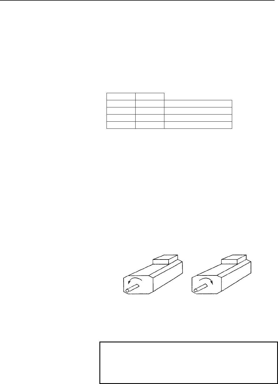
(2) While SFRA is 1, the spindle motor rotates counterclockwise as
viewed from the shaft side at a specified speed (a positive value).
While SRVA is 1, the spindle motor rotates clockwise as viewed
from the shaft side according to the speed command (a positive
value).
(3) When SFRA is set to 0 or when SRVA is set to 0, the spindle
motor is stopped by regenerative braking. After the spindle motor
is stopped, the power element excitation signal is turned off to
interrupt power supply to the spindle motor.
NOTE
If the forward rotation command signal (SFRA) and
reverse rotation command signal (SRVA) are
specified at the same time, the spindle status error
(error 14) occurs, and the spindle motor is stopped.
When SFR = 1 When SRV = 1
Contents Summary of AC Spindle Motor Alpha i / Beta i Series Parameter manual
- Page 1FANUC AC SPINDLE MOTOR @* series FANUC AC SPINDLE MOTOR #* series PARAMETER MANUAL B-65280EN/05
- Page 2• No part of this manual may be reproduced in any form. • All specifications and designs are subject to change without notice. In this manual we have tried as much as possible to describe all the various matters. However, we cannot describe all the matters which must not be done, or which cannot be
- Page 3B-65280EN/05 DEFINITION OF WARNING, CAUTION, AND NOTE DEFINITION OF WARNING, CAUTION, AND NOTE This manual includes safety precautions for protecting the user and preventing damage to the machine. Precautions are classified into Warning and Caution according to their bearing on safety. Also, supplem
- Page 4
- Page 5B-65280EN/05 PREFACE PREFACE This manual describes the parameters and functions of the FANUC servo amplifier αi/βi series spindle. This manual is divided into four parts and appendix. Part I describes the αi series spindle, Part II describes the βi series spindle, Part III describes the αCi series s
- Page 6PREFACE B-65280EN/05 (8) FANUC AC SPINDLE MOTOR αi/βi series PARAMETER MANUAL (B-65280EN) (9) FANUC AC SPINDLE MOTOR αiB series DESCRIPTIONS (B-65292EN) p-2
- Page 7B-65280EN/05 TABLE OF CONTENTS TABLE OF CONTENTS DEFINITION OF WARNING, CAUTION, AND NOTE .................................s-1 PREFACE ....................................................................................................p-1 I. FANUC AC SPINDLE MOTOR αi series 1 START-UP...............
- Page 8TABLE OF CONTENTS B-65280EN/05 2.2.9 Details of Related Parameters ................................................................................63 2.2.10 Calculating the Position Gain for Orientation ........................................................68 2.2.11 Adjusting the Orientation Stop
- Page 9B-65280EN/05 TABLE OF CONTENTS 2.5.11 Diagnosis (Diagnosis Screen)...............................................................................156 2.5.12 Alarm ....................................................................................................................157 2.6 SPECIFICATIONS
- Page 10TABLE OF CONTENTS B-65280EN/05 5.1.6 List of Related Parameters....................................................................................230 5.1.7 Details of Related Parameters ..............................................................................231 5.1.8 Parameter-specified Switc
- Page 11B-65280EN/05 TABLE OF CONTENTS 5.5.2 Series and Editions of Applicable Spindle Software............................................278 5.5.3 Specification.........................................................................................................279 5.5.4 I/O Signals (CNC ↔ PMC) .......
- Page 12TABLE OF CONTENTS B-65280EN/05 5.9.2 Series and Editions of Applicable Spindle Software............................................314 5.9.3 Configuration .......................................................................................................315 5.9.4 Description ....................
- Page 13B-65280EN/05 TABLE OF CONTENTS 1.2.2 Automatic Spindle Parameter Initialization .........................................................351 1.2.3 Diagnosis (Diagnosis Screen)...............................................................................352 1.2.4 Alarm ..............................
- Page 14TABLE OF CONTENTS B-65280EN/05 2.3.9 Adjustment Procedure ..........................................................................................366 2.3.10 Diagnosis (Diagnosis Screen)...............................................................................366 2.3.11 Alarm .................
- Page 15B-65280EN/05 TABLE OF CONTENTS 3.2 OUTPUT SIGNALS (SVPM→CNC→PMC) ............................................... 379 3.2.1 List of Output Signals...........................................................................................379 3.2.2 Explanation of Output Signals ........................
- Page 16TABLE OF CONTENTS B-65280EN/05 5.4 UNEXPECTED DISTURBANCE TORQUE DETECTION FUNCTION (Optional function) ..................................................................................... 394 5.4.1 Overview ...........................................................................................
- Page 17B-65280EN/05 TABLE OF CONTENTS 2.2.6 I/O Signals (CNC↔PMC) ...................................................................................426 2.2.7 Examples of Sequences ........................................................................................426 2.2.8 Related Parameters .........
- Page 18TABLE OF CONTENTS B-65280EN/05 3.1 INPUT SIGNALS (PMC→CNC→SPM)...................................................... 477 3.1.1 List of Input Signals .............................................................................................477 3.1.2 Explanation of Input Signals ...................
- Page 19B-65280EN/05 TABLE OF CONTENTS 1.5.2 Magnetic Pole Detection Operation .....................................................................501 1.5.3 AMR Offset Function...........................................................................................503 1.5.4 I/O Signals (CNC ↔ PMC) ......
- Page 20TABLE OF CONTENTS B-65280EN/05 2.3.9 Adjustment Procedure ..........................................................................................540 2.3.10 Diagnosis (Diagnosis Screen)...............................................................................545 2.3.11 Alarm .................
- Page 21B-65280EN/05 TABLE OF CONTENTS 3.2 OUTPUT SIGNALS (SPM→CNC→PMC).................................................. 590 3.2.1 List of Output Signals...........................................................................................590 3.2.2 Explanation of Output Signals .......................
- Page 22TABLE OF CONTENTS B-65280EN/05 5.4.8 Spindle Data Used in Tuning ...............................................................................610 5.4.9 Tuning Procedure .................................................................................................610 5.5 SPINDLE ORIENTATION DURI
- Page 23B-65280EN/05 TABLE OF CONTENTS 5.8.9 Diagnosis Signal Related to Spindle EGB ...........................................................628 5.8.10 Status Errors Related to Spindle EGB..................................................................628 5.8.11 Alarms .................................
- Page 24TABLE OF CONTENTS B-65280EN/05 E.3.2 Output Signals (CNC→PMC)..............................................................................701 F OBSERVING DATA USING THE SERVO GUIDE .............................. 704 F.1 SERIES AND EDITIONS OF APPLICABLE SPINDLE SOFTWARE......... 705 F.2 SPINDLE DAT
- Page 25I. FANUC AC SPINDLE MOTOR αi series
- Page 26
- Page 27B-65280EN/05 FANUC AC SPINDLE MOTOR αi series 1.START-UP 1 START-UP -3-
- Page 281.START-UP FANUC AC SPINDLE MOTOR αi series B-65280EN/05 1.1 START-UP PROCEDURE A. Check the spindle-related specifications. - CNC model - Spindle motor - Power supply module - Spindle amplifier module - Detector system B. Check all connections. (See DESCRIPTIONS (B-65272EN).) C. Prepare and check t
- Page 29B-65280EN/05 FANUC AC SPINDLE MOTOR αi series 1.START-UP 1.2 SPINDLE SERIAL INTERFACE Optional function 1.2.1 Parameters Related to Spindle Serial Output This subsection provides a list of the parameters related to spindle serial output only. For details of each parameter, refer to the Connection Ma
- Page 301.START-UP FANUC AC SPINDLE MOTOR αi series B-65280EN/05 1.2.2 Automatic Spindle Parameter Initialization (1) Parameter list Parameter No. 15i 16i 30i Description 5607#0 4019#7 4019#7 Function for automatically initializing spindle parameters 3133 4133 4133 Spindle motor model code (2) Procedure for
- Page 31B-65280EN/05 FANUC AC SPINDLE MOTOR αi series 1.START-UP 1.2.3 Diagnosis (Diagnosis Screen) This subsection provides a list of the diagnosis (diagnosis screen) indications related to spindle serial output only. For details, refer to the Connection Manual (Function) of each CNC. (a) For Series 16i/18
- Page 321.START-UP FANUC AC SPINDLE MOTOR αi series B-65280EN/05 1.2.4 Alarm This subsection provides a list of the alarms related to spindle serial output only. For details of each alarm, refer to the Connection Manual (Function) of each CNC. (a) For Series 16i/18i/21i “FANUC Series 16i/18i/21i-MODEL B CON
- Page 33B-65280EN/05 FANUC AC SPINDLE MOTOR αi series 1.START-UP Alarm No. Description 15i 30i SP0230 The value set in parameter No. 5841 is not within the allowable range. SP0970 Spindle control initialization was not terminated. SP0976 No amplifier number could be set for a serial spindle amplifier.
- Page 341.START-UP FANUC AC SPINDLE MOTOR αi series B-65280EN/05 1.3 PARAMETERS RELATED TO DETECTORS NOTE 1 Note that the specifications of parameters related to detectors for the αi series spindle amplifiers differ from those of parameters for the α series spindle amplifiers. 2 The terms "motor sensor" and
- Page 35B-65280EN/05 FANUC AC SPINDLE MOTOR αi series 1.START-UP Parameter No. Denominator of arbitrary gear ratio between motor sensor and 3171 4171 4171 spindle 3173 4173 4173 (This data is selected by spindle control input signal CTH1A.) Numerator of arbitrary gear ratio between motor sensor and 3172 417
- Page 361.START-UP FANUC AC SPINDLE MOTOR αi series B-65280EN/05 1.3.2 Details of Parameters for Detectors This subsection details the serial spindle parameters (in the four thousands for 16i, and in the four thousands for 30i, and in the three thousands for 15i) among the detector-related parameters. For d
- Page 37B-65280EN/05 FANUC AC SPINDLE MOTOR αi series 1.START-UP SSTYP3 SSTYP2 SSTYP1 SSTYP0 Spindle sensor type 0 0 0 0 None (No position control function is used.) 0 0 0 1 Uses the motor sensor for position feedback 0 0 1 0 α position coder 0 0 1 1 Separate BZi sensor, CZi sensor 0 1 0 0 α position coder
- Page 381.START-UP FANUC AC SPINDLE MOTOR αi series B-65280EN/05 15i 16i 30i #7 #6 #5 #4 #3 #2 #1 #0 3006 4006 4006 GRUNIT GRUNIT Sets a gear ratio setting resolution: 0 : 1/100 unit 1 : 1/1000 unit Select a gear ratio data setting resolution from the following: (a) Resolution based on motor rotation increa
- Page 39B-65280EN/05 FANUC AC SPINDLE MOTOR αi series 1.START-UP 15i 16i 30i #7 #6 #5 #4 #3 #2 #1 #0 3010 4010 4010 MSTYP2 MSTYP1 MSTYP0 MSTYP2, MSTYP1, MSTYP0 Motor sensor type This parameter sets the type of a detector built into the motor (detector to be connected to JYA2). MSTYP2 MSTYP1 MSTYP0 Motor sen
- Page 401.START-UP FANUC AC SPINDLE MOTOR αi series B-65280EN/05 RFCHK2 Determines whether to detect the alarm related to threading position detection signal feedback (SPM alarm 46). 0 : Does not detect alarms. 1 : Detects alarms. RFCHK3 Setting of the function of detecting the one-rotation signal again eac
- Page 41B-65280EN/05 FANUC AC SPINDLE MOTOR αi series 1.START-UP 15i 16i 30i 3056 4056 4056 Gear ratio (HIGH) CTH1A=0, CTH2A=0 3057 4057 4057 Gear ratio (MEDIUM HIGH) CTH1A=0, CTH2A=1 3058 4058 4058 Gear ratio (MEDIUM LOW) CTH1A=1, CTH2A=0 3059 4059 4059 Gear ratio (LOW) CTH1A=1, CTH2A=1 Unit of data : (Mot
- Page 421.START-UP FANUC AC SPINDLE MOTOR αi series B-65280EN/05 15i 16i 30i Denominator of arbitrary gear ratio between motor sensor and spindle (HIGH) 3171 4171 4171 CTH1A=0 Numerator of arbitrary gear ratio between motor sensor and spindle (HIGH) 3172 4172 4172 CTH1A=0 Denominator of arbitrary gear ratio
- Page 43B-65280EN/05 FANUC AC SPINDLE MOTOR αi series 1.START-UP 15i 16i 30i 3355 4355 4355 Motor sensor signal amplitude ratio compensation 3357 4357 4357 Spindle sensor signal amplitude ratio compensation Unit of data : 1% Valid data range : -8 to 8 Standard setting : 0 These parameters set an amplitude r
- Page 441.START-UP FANUC AC SPINDLE MOTOR αi series B-65280EN/05 15i 16i Denominator of arbitrary gear ratio between spindle sensor and spindle 3500 4500 (HIGH) CTH1A=0 Numerator of arbitrary gear ratio between spindle sensor and spindle (HIGH) 3501 4501 CTH1A=0 Denominator of arbitrary gear ratio between s
- Page 45B-65280EN/05 FANUC AC SPINDLE MOTOR αi series 1.START-UP 1.3.3 Typical Detector Configurations This subsection describes typical detector configurations and the parameter setting procedures for the detector configurations. With the αi series spindle, the detector circuitry hardware is set according
- Page 461.START-UP FANUC AC SPINDLE MOTOR αi series B-65280EN/05 (2) When the α position coder is used [Sample system configuration] Spindle motor with built-in Mi sensor (or MZi sensor) JYA2 Spindle α position coder SPM TYPE A JYA3 Directly connected or connected with a gear or timing belt at a ratio of 1:
- Page 47B-65280EN/05 FANUC AC SPINDLE MOTOR αi series 1.START-UP (3) When the α position coder S is used [Sample system configuration] Spindle motor with built-in Mi sensor (or MZi sensor) JYA2 Spindle α position coder S SPM TYPE B JYA4 Directly connected or connected with a gear or timing belt at a ratio o
- Page 481.START-UP FANUC AC SPINDLE MOTOR αi series B-65280EN/05 (4) When the MZi, BZi, or CZi sensor is used [Sample system configuration 1] Spindle motor with built-in MZi sensor Spindle [Sample system configuration 2] BZi sensor or CZi sensor Spindle + built-in motor [Sample system configuration 3] Spind
- Page 49B-65280EN/05 FANUC AC SPINDLE MOTOR αi series 1.START-UP (5) When the separate type BZi sensor or separate type CZi sensor is used [Sample system configuration] Spindle motor with built-in Mi sensor (or MZi sensor) Spindle BZi sensor or CZi sensor Parameter No. Settings Description Depends on the Ro
- Page 501.START-UP FANUC AC SPINDLE MOTOR αi series B-65280EN/05 (6) When the external one-rotation signal (proximity switch) is used [Sample system configuration] Spindle motor with built-in Mi sensor (or MZi sensor) Spindle External one-rotation signal (proximity switch) Gear or timing belt Parameter No.
- Page 51B-65280EN/05 FANUC AC SPINDLE MOTOR αi series 1.START-UP (7) When the axis on which the spindle sensor is mounted is not the spindle [Sample system configuration] Spindle motor with built-in Mi sensor Gear or timing belt JYA2 Medial axis α position coder SPM TYPE A JYA3 Directly connected or connect
- Page 522.EXPLANATION OF OPERATION MODES FANUC AC SPINDLE MOTOR αi series B-65280EN/05 2 EXPLANATION OF OPERATION MODES - 28 -
- Page 53B-65280EN/05 FANUC AC SPINDLE MOTOR αi series 2.EXPLANATION OF OPERATION MODES 2.1 VELOCITY CONTROL MODE 2.1.1 Start-up Procedure A. Check that the serial spindle starts up normally and is ready for operation. B. Prepare and check the PMC ladder. C. Set the detector-related parameters according to t
- Page 542.EXPLANATION OF OPERATION MODES FANUC AC SPINDLE MOTOR αi series B-65280EN/05 2.1.4 List of I/O Signals (CNC↔PMC) This subsection provides a list of the I/O signals related to the velocity control mode only. For details of each signal, refer to the Connection Manual (Function) of each CNC. (a) For
- Page 55B-65280EN/05 FANUC AC SPINDLE MOTOR αi series 2.EXPLANATION OF OPERATION MODES (b) Series 30i #7 #6 #5 #4 #3 #2 #1 #0 Common to all axes G027 *SSTP2 *SSTP1 SWS2 SWS1 (*1) (*1) (*1) (*1) Common to all axes G028 GR2 GR1 Common to all axes G029 *SSTP SOR SAR Common to all axes G030 SOV7 SOV6 SOV5 SOV4
- Page 562.EXPLANATION OF OPERATION MODES FANUC AC SPINDLE MOTOR αi series B-65280EN/05 (2) Output signals (CNC→PMC) (a) Series 16i #7 #6 #5 #4 #3 #2 #1 #0 F001 ENB F007 SF F022 S07 S06 S05 S04 S03 S02 S01 S00 F023 S15 S14 S13 S12 S11 S10 S09 S08 F024 S23 S22 S21 S20 S19 S18 S17 S16 F025 S31 S30 S29 S28 S27
- Page 57B-65280EN/05 FANUC AC SPINDLE MOTOR αi series 2.EXPLANATION OF OPERATION MODES (b) Series 15i #7 #6 #5 #4 #3 #2 #1 #0 Common to all axes F008 SF Common to all axes F020 S7 S6 S5 S4 S3 S2 S1 S0 Common to all axes F021 S15 S14 S13 S12 S11 S10 S09 S08 Common to all axes F022 S23 S22 S21 S20 S19 S18 S17
- Page 582.EXPLANATION OF OPERATION MODES FANUC AC SPINDLE MOTOR αi series B-65280EN/05 2.1.5 Related Parameters Parameter No. Description 15i 16i 30i 3705#0 3705#0 Sets SF signal output and the S code for an S command. 3705#2 3705#2 Gear switch method (M series only) 3705#4 3705#4 Sets SF signal outpu
- Page 59B-65280EN/05 FANUC AC SPINDLE MOTOR αi series 2.EXPLANATION OF OPERATION MODES Parameter No. Description 15i 16i 30i 3009#6 4009#6 4009#6 Analog override type 3012#7 4012#7 4012#7 Sets the spindle HRV function. (Set "1".) 5607#0 4019#7 4019#7 Automatic spindle parameter setting function 3352#1 4352#
- Page 602.EXPLANATION OF OPERATION MODES FANUC AC SPINDLE MOTOR αi series B-65280EN/05 2.1.6 Details of Related Parameters This subsection details the serial spindle parameters (in the four thousands for 16i , and in the four thousands for 30i, and in the three thousands for 15i) among the parameters relate
- Page 61B-65280EN/05 FANUC AC SPINDLE MOTOR αi series 2.EXPLANATION OF OPERATION MODES NOTE The control method usable with the αi series spindle is spindle HRV control only. The conventional control method is not supported. 16i 30i #7 #6 #5 #4 #3 #2 #1 #0 4019 4019 PRLOAD PRLOAD Automatic parameter setting
- Page 622.EXPLANATION OF OPERATION MODES FANUC AC SPINDLE MOTOR αi series B-65280EN/05 WARNING The spindle motor may rotate at the maximum spindle motor speed specified by this parameter. Therefore, this parameter must not be set to a value greater than the maximum rotation speed indicated by the specificat
- Page 63B-65280EN/05 FANUC AC SPINDLE MOTOR αi series 2.EXPLANATION OF OPERATION MODES Torque limitation Torque limitation command command Description LOW(TLMLA) HIGH(TLMHA) 0 0 No torque limitation is imposed. The torque is limited to the value 0 1 set in this parameter. 1 0 The torque is limited to a half
- Page 642.EXPLANATION OF OPERATION MODES FANUC AC SPINDLE MOTOR αi series B-65280EN/05 Setting data Description Pattern 1 Pattern 2 Pattern 3 No output limitation is imposed. 0 0 0 A. Output is limited only at acceleration time 1 4 7 and deceleration time. B. Output is not limited at acceleration time and d
- Page 65B-65280EN/05 FANUC AC SPINDLE MOTOR αi series 2.EXPLANATION OF OPERATION MODES [Output limitation pattern 3]--- Setting data = 7, 8, 9 --- Output Pm Catalog value Limit value 0 Speed 0 Nb Nout Nm 100 Nout = × Nb Setting in parameter No. 4029 15i 16i 30i 3029 4029 4029 Output limitation value Unit of
- Page 662.EXPLANATION OF OPERATION MODES FANUC AC SPINDLE MOTOR αi series B-65280EN/05 15i 16i 30i 3040 4040 4040 Velocity loop proportional gain on velocity control mode (HIGH) CTH1A=0 3041 4041 4041 Velocity loop proportional gain on velocity control mode (LOW) CTH1A=1 Unit of data : Valid data range : 0
- Page 67B-65280EN/05 FANUC AC SPINDLE MOTOR αi series 2.EXPLANATION OF OPERATION MODES 15i 16i 30i 3081 4081 4081 Delay time until the motor power is turned off Unit of data : 10ms Valid data range : 0 to 1000 Standard setting value : 20 (200ms) This parameter sets a period of time from the stop of the moto
- Page 682.EXPLANATION OF OPERATION MODES FANUC AC SPINDLE MOTOR αi series B-65280EN/05 15i 16i 30i 3083 4083 4083 Motor voltage setting on velocity control mode 3136 4136 4136 Motor voltage setting on velocity control mode (for low-speed characteristics) Unit of data : 1% Valid data range : 0 to 100 Standar
- Page 69B-65280EN/05 FANUC AC SPINDLE MOTOR αi series 2.EXPLANATION OF OPERATION MODES 15i 16i 30i 3508 4508 4508 Rate of change in acceleration at soft start/stop Unit of data : 10min-1/sec2 Valid data range : 0 to 32767 Standard setting : 0 This parameter sets the jerk (the rate of change in acceleration)
- Page 702.EXPLANATION OF OPERATION MODES FANUC AC SPINDLE MOTOR αi series B-65280EN/05 2.1.7 Troubleshooting If the spindle motor does not operate normally, take an action by referencing the items listed below according to the state of trouble. For an action to be taken when an alarm is issued, refer to the
- Page 71B-65280EN/05 FANUC AC SPINDLE MOTOR αi series 2.EXPLANATION OF OPERATION MODES (3) Check the input signals. (a) Input signals for spindle control (PMC → CNC) 15i 16i 30i #7 #6 #5 #4 #3 #2 #1 #0 1st- G227 G070 G070 MRDYA SFRA SRVA 2nd- G235 G074 G074 MRDYB SFRB SRVB 1st- G226 G071 G071 *ESPA 2nd- G23
- Page 722.EXPLANATION OF OPERATION MODES FANUC AC SPINDLE MOTOR αi series B-65280EN/05 (iii) When the motor vibrates and makes an abnormal sound when rotating (1) Check the feedback signal. (a) Feedback signal level (Refer to Maintenance Manual.) (b) Shielding and grounding (Refer to Descriptions.) (2) Chec
- Page 73B-65280EN/05 FANUC AC SPINDLE MOTOR αi series 2.EXPLANATION OF OPERATION MODES (v) When the cutting capability is degraded (1) Check the parameter settings. (a) Parameter data for each motor model (b) Output limitation pattern and output limitation value 15i 16i 30i Description 3028 4028 4028 Output
- Page 742.EXPLANATION OF OPERATION MODES FANUC AC SPINDLE MOTOR αi series B-65280EN/05 2.2 POSITION CODER METHOD SPINDLE ORIENTATION Optional function 2.2.1 Start-up Procedure A. Check that operation in the velocity control mode is enabled. B. Prepare and check the ladder program for spindle orientation. C.
- Page 75B-65280EN/05 FANUC AC SPINDLE MOTOR αi series 2.EXPLANATION OF OPERATION MODES 2.2.2 Overview Unlike a function for stopping the spindle at a predetermined position mechanically, for example, by using a stopper, the spindle orientation function stops the spindle at a predetermined position by direct
- Page 762.EXPLANATION OF OPERATION MODES FANUC AC SPINDLE MOTOR αi series B-65280EN/05 2.2.4 System Configuration The system configurations that enable the use of the position coder method orientation function are shown below. (1) When the α position coder is used Spindle motor with built-in Mi sensor (or M
- Page 77B-65280EN/05 FANUC AC SPINDLE MOTOR αi series 2.EXPLANATION OF OPERATION MODES (4) When the spindle motor with built-in MZi sensor is used Spindle motor with built-in MZi sensor JYA2 Spindle SPM TYPE A Directly connected or connected with a gear or timing belt at a ratio of 1:1 (5) When the separate
- Page 782.EXPLANATION OF OPERATION MODES FANUC AC SPINDLE MOTOR αi series B-65280EN/05 (6) When the external one-rotation signal (proximity switch) is used Spindle motor with built-in Mi sensor (or MZi sensor) Spindle External one-rotation signal switch (proximity switch) Gear or timing belt NOTE 1 For stab
- Page 79B-65280EN/05 FANUC AC SPINDLE MOTOR αi series 2.EXPLANATION OF OPERATION MODES 2.2.6 I/O Signals (CNC ↔ PMC) (1) Address list of Input signals (PMC → CNC) 15i 16i 30i #7 #6 #5 #4 #3 #2 #1 #0 1st- G227 G070 G070 ORCMA CTH1A CTH2A 2nd- G235 G074 G074 ORCMB CTH1B CTH2B 1st- G229 G072 G072 NRROA ROTAA I
- Page 802.EXPLANATION OF OPERATION MODES FANUC AC SPINDLE MOTOR αi series B-65280EN/05 (b) Clutch/gear signals (CTH1A, CTH2A) (i) These signals are used to select spindle control parameters (position gain, gear ratio, and velocity loop gain) when there are two or more gear change stages between the spindle
- Page 81B-65280EN/05 FANUC AC SPINDLE MOTOR αi series 2.EXPLANATION OF OPERATION MODES (f) Spindle orientation external stop position command (SHA11 to SHA00) (i) With the stop position external setting type spindle orientation function, a stop position is set. A stop position is determined by the expressio
- Page 822.EXPLANATION OF OPERATION MODES FANUC AC SPINDLE MOTOR αi series B-65280EN/05 (iii) The orientation completion signal is output when the spindle is in the neighborhood of a predetermined position. This means that this signal does not represent a complete stop signal. With some machines, the operati
- Page 83B-65280EN/05 FANUC AC SPINDLE MOTOR αi series 2.EXPLANATION OF OPERATION MODES 2.2.7 Examples of Sequences (1) Orientation command at stop time Orientation command Stop Stop CW direction Motor speed CCW direction Note Orientation completion signal ATC operation ATC operation Start Completion NOTE Th
- Page 842.EXPLANATION OF OPERATION MODES FANUC AC SPINDLE MOTOR αi series B-65280EN/05 (3) Stop position external setting type spindle orientation Spindle orientation command ORCMA Spindle orientation stop position command SHA00-11 Spindle orientation stop position change command INDXA Spindle orientation s
- Page 85B-65280EN/05 FANUC AC SPINDLE MOTOR αi series 2.EXPLANATION OF OPERATION MODES • The rotation direction of the spindle motor depends on the spindle orientation stop position change rotation direction command (ROTAA) and the spindle orientation stop position change shortcut command (NRROA). NOTE The
- Page 862.EXPLANATION OF OPERATION MODES FANUC AC SPINDLE MOTOR αi series B-65280EN/05 2.2.8 Related Parameters Parameter No. Description 15i 16i 30i Specifies whether to use the spindle orientation function. (Set this bit to 1.) 3015#0 4015#0 4015#0 (The CNC software option is required.) Specifies whether
- Page 87B-65280EN/05 FANUC AC SPINDLE MOTOR αi series 2.EXPLANATION OF OPERATION MODES 2.2.9 Details of Related Parameters 15i 16i 30i #7 #6 #5 #4 #3 #2 #1 #0 3003 4003 4003 DIRCT2 DIRCT1 PCMGSL DIRCT2, DIRCT1 Setting of rotation direction at spindle orientation DIRCT2 DIRCT1 Rotation direction at spindle o
- Page 882.EXPLANATION OF OPERATION MODES FANUC AC SPINDLE MOTOR αi series B-65280EN/05 15i 16i 30i #7 #6 #5 #4 #3 #2 #1 #0 3017 4017 4017 NRROEN NRROEN Specifies whether to use the shortcut function when orientation is specified in the stop state. 0 : Does not use the function. 1 : Uses the function. When t
- Page 89B-65280EN/05 FANUC AC SPINDLE MOTOR αi series 2.EXPLANATION OF OPERATION MODES 15i 16i 30i 3042 4042 4042 Velocity loop proportional gain on orientation (HIGH) CTH1A=0 3043 4043 4043 Velocity loop proportional gain on orientation (LOW) CTH1A=1 Unit of data : Valid data range : 0 to 32767 Standard se
- Page 902.EXPLANATION OF OPERATION MODES FANUC AC SPINDLE MOTOR αi series B-65280EN/05 15i 16i 30i 3060 4060 4060 Position gain on orientation (HIGH) CTH1A=0, CTH2A=0 3061 4061 4061 Position gain on orientation (MEDIUM HIGH) CTH1A=0, CTH2A=1 3062 4062 4062 Position gain on orientation (MEDIUM LOW) CTH1A=1,
- Page 91B-65280EN/05 FANUC AC SPINDLE MOTOR αi series 2.EXPLANATION OF OPERATION MODES 15i 16i 30i 3077 4077 4077 Orientation stop position shift value Unit of data : ±1 pulse unit (360 degrees/4096) Valid data range : -4095 to 4095 Standard setting : 0 In the position coder method orientation, set this dat
- Page 922.EXPLANATION OF OPERATION MODES FANUC AC SPINDLE MOTOR αi series B-65280EN/05 2.2.10 Calculating the Position Gain for Orientation (1) When the spindle orientation speed (parameter No. 4038) is set to 0, the orientation speed is determined using the following expression: Nori = 60 × PG × Rori × GEA
- Page 93B-65280EN/05 FANUC AC SPINDLE MOTOR αi series 2.EXPLANATION OF OPERATION MODES 2.2.11 Adjusting the Orientation Stop Position Shift Parameter Adjust the orientation stop position shift parameter by following the procedure below. (1) Adjustment using diagnosis screen No. 445 (spindle position data di
- Page 942.EXPLANATION OF OPERATION MODES FANUC AC SPINDLE MOTOR αi series B-65280EN/05 (2) Adjustment using the spindle check board (a) Specify parameters as follows: No.4016#7=0 No.4031=0 (When external signals are used for setting, set the SHA11 to SHA00 DI signals to 0.) No.4077=0 (b) To display the posi
- Page 95B-65280EN/05 FANUC AC SPINDLE MOTOR αi series 2.EXPLANATION OF OPERATION MODES 2.2.12 Calculating the Orientation Time The time required for orientation differs between the first orientation (before the one-rotation signal has first been detected) and the second and subsequent orientations (once the
- Page 962.EXPLANATION OF OPERATION MODES FANUC AC SPINDLE MOTOR αi series B-65280EN/05 (d) t4 is the time from the start of deceleration until orientation has been completed. Let the orientation completion width be within ±10 pulses. Then, t4 can be calculated as follows: 1 4096 × Rori t4 = × ln PG 10 (e) T
- Page 97B-65280EN/05 FANUC AC SPINDLE MOTOR αi series 2.EXPLANATION OF OPERATION MODES 2.3 RIGID TAPPING Optional function 2.3.1 Start-up Procedure A. Check that operation in the velocity control mode is enabled. B. Prepare and check the rigid tapping ladder program. C. Set up the detector-related parameter
- Page 982.EXPLANATION OF OPERATION MODES FANUC AC SPINDLE MOTOR αi series B-65280EN/05 2.3.3 System Configuration The system configurations that enable the use of rigid tapping are shown below. (1) When the α position coder is used Spindle motor with built-in Mi sensor (or MZi sensor) JYA2 Spindle α positio
- Page 99B-65280EN/05 FANUC AC SPINDLE MOTOR αi series 2.EXPLANATION OF OPERATION MODES (4) When the spindle motor with built-in Mi sensor (or MZi sensor) is used Spindle motor with built-in Mi sensor (or MZi sensor) JYA2 Spindle SPM TYPE A Directly connected at a ratio of 1:1 or connected with a gear or tim
- Page 1002.EXPLANATION OF OPERATION MODES FANUC AC SPINDLE MOTOR αi series B-65280EN/05 (5) When the separate type BZi sensor or separate type CZi sensor is used Spindle motor with built-in Mi sensor (or MZi sensor) Spindle BZi sensor or CZi sensor (6) When the external one-rotation signal (proximity switch)
- Page 101B-65280EN/05 FANUC AC SPINDLE MOTOR αi series 2.EXPLANATION OF OPERATION MODES 2.3.4 List of I/O Signals (CNC ↔ PMC) This subsection provides a list of the I/O signals related to rigid tapping only. For details of each signal, refer to the Connection Manual (Function) of each CNC. (a) For Series 16i
- Page 1022.EXPLANATION OF OPERATION MODES FANUC AC SPINDLE MOTOR αi series B-65280EN/05 (b) Series 30i #7 #6 #5 #4 #3 #2 #1 #0 G027 SWS2 SWS1 (*1) (*1) G028 GR2 GR1 G029 GR22 GR21 (*2) (*2) G061 RGTAP NOTE 1 The rigid tapping of the second spindle is available by the multi-spindle control function. When SWS1
- Page 103B-65280EN/05 FANUC AC SPINDLE MOTOR αi series 2.EXPLANATION OF OPERATION MODES (b) Series 30i #7 #6 #5 #4 #3 #2 #1 #0 F034 GR3O GR2O GR1O (*1) (*1) (*1) F065 RGSPM RGSPP (*1) (*1) F075 RTAP NOTE *1 These signals are effective when M series. (c) Series 15i #7 #6 #5 #4 #3 #2 #1 #0 F040 RTAP F155 RSPC
- Page 1042.EXPLANATION OF OPERATION MODES FANUC AC SPINDLE MOTOR αi series B-65280EN/05 2.3.6 Related Parameters Parameter No. Description 15i 16i 16i - 5210 5210 M code of rigid tapping command 5202#0 5202#0 Whether to perform orientation (reference position return) when starting 5606#6 (M series only) (M s
- Page 105B-65280EN/05 FANUC AC SPINDLE MOTOR αi series 2.EXPLANATION OF OPERATION MODES Parameter No. Description 15i 16i 16i 5877 5313 5313 Allowable level of position error of spindle at stop 5853 Backlash of spindle 5856 5321 to 5324 5321 to 5324 (16i: No. 5322 and No. 5324 are used for the T series only.
- Page 1062.EXPLANATION OF OPERATION MODES FANUC AC SPINDLE MOTOR αi series B-65280EN/05 2.3.7 Details of Related Parameters This subsection details the serial spindle parameters (in the four thousands for 16i, and in the four thousands for 30i, and in the three thousands for 15i) among the parameters related
- Page 107B-65280EN/05 FANUC AC SPINDLE MOTOR αi series 2.EXPLANATION OF OPERATION MODES 15i 16i 30i #7 #6 #5 #4 #3 #2 #1 #0 3006 4006 4006 RGTCMR RGTCMR Sets the command arbitrary gear ratio function (CMR) on rigid tapping. 0 : Disables the command arbitrary gear ratio function. 1 : Enables the specified arb
- Page 1082.EXPLANATION OF OPERATION MODES FANUC AC SPINDLE MOTOR αi series B-65280EN/05 15i 16i 30i Velocity loop proportional gain on servo mode/spindle synchronous control 3044 4044 4044 (HIGH) CTH1A=0 Velocity loop proportional gain on servo mode/spindle synchronous control 3045 4045 4045 (LOW) CTH1A=1 Un
- Page 109B-65280EN/05 FANUC AC SPINDLE MOTOR αi series 2.EXPLANATION OF OPERATION MODES NOTE When an improper value is set in these parameters, an unexpected operation can occur. For example, the spindle can continue rotating without stopping at the time of orientation. So, be sure to set a proper gear ratio
- Page 1102.EXPLANATION OF OPERATION MODES FANUC AC SPINDLE MOTOR αi series B-65280EN/05 15i 16i 30i 3074 4074 4074 Reference position return speed on Cs contouring control/servo mode Unit of data : 1min-1 Valid data range : 0 to 32767 Standard setting value : 0 • When 0 is set The value calculated from the p
- Page 111B-65280EN/05 FANUC AC SPINDLE MOTOR αi series 2.EXPLANATION OF OPERATION MODES 15i 16i 30i 3091 4091 4091 Position gain change ratio at reference position return time on servo mode Unit of data : 1% Valid data range : 0 to 100 Standard setting value : 100 This parameter sets a position gain change r
- Page 1122.EXPLANATION OF OPERATION MODES FANUC AC SPINDLE MOTOR αi series B-65280EN/05 15i 16i 30i Denominator of an arbitrary gear ratio between the motor sensor and spindle 3171 4171 4171 (HIGH) CTH1A=0 Numerator of an arbitrary gear ratio between the motor sensor and spindle 3172 4172 4172 (HIGH) CTH1A=0
- Page 113B-65280EN/05 FANUC AC SPINDLE MOTOR αi series 2.EXPLANATION OF OPERATION MODES 2.3.8 Parameter Setting Procedure (1) Command arbitrary gear ratio (CMR) (a) For a configuration in which the sensor built into the motor is used for position detection and the gear ratio between the spindle and motor is
- Page 1142.EXPLANATION OF OPERATION MODES FANUC AC SPINDLE MOTOR αi series B-65280EN/05 [Sample system configuration 3] When orientation by the external one-rotation signal is used in a configuration in which the gear ratio between the spindle and motor is not 1:1, the detection arbitrary gear ratio function
- Page 115B-65280EN/05 FANUC AC SPINDLE MOTOR αi series 2.EXPLANATION OF OPERATION MODES (2) Set the gear teeth number of the position coder side. Each parameter is selected according to the gear selection signal. Standard machining [M series]: GR3O, GR2O, GR1O Turning [T series] and machining[M series] with
- Page 1162.EXPLANATION OF OPERATION MODES FANUC AC SPINDLE MOTOR αi series B-65280EN/05 [Series 15i] Gear signal Parameter No. Gear teeth number of Gear teeth number of CTH1A CTH2A spindle side position coder side 0 0 5852 5851 0 1 5855 5854 1 0 5858 5857 1 1 5861 5860 (2) Gear ratio between the spindle and
- Page 117B-65280EN/05 FANUC AC SPINDLE MOTOR αi series 2.EXPLANATION OF OPERATION MODES (3) Position gain In rigid tapping, the tapping axis and spindle are controlled to be synchronized. So, the position gains of the tapping axis and spindle must be set to the same value. [Series 16i] The position gain para
- Page 1182.EXPLANATION OF OPERATION MODES FANUC AC SPINDLE MOTOR αi series B-65280EN/05 [Series 30i] The position gain parameter of the tapping axis in the rigid tapping is selected as follows according to the gear selection signal. Standard machining [M series]: GR3O, GR2O, GR1O Turning [T series] and machi
- Page 119B-65280EN/05 FANUC AC SPINDLE MOTOR αi series 2.EXPLANATION OF OPERATION MODES [Series 15i] In the rigid tapping, the same parameter address data is used for the position gain of the tapping axis and the spindle. Each position gain is selected as follows according to the gear selection signal (CTH1A
- Page 1202.EXPLANATION OF OPERATION MODES FANUC AC SPINDLE MOTOR αi series B-65280EN/05 Turning [T series] and machining [M series] with surface speed constant Gear signal Spindle max. speed at Time constant Time constant rigid tapping Fst. sp Snd. sp (Cutting in) (Cutting out) Parameter No. Parameter No. Pa
- Page 121B-65280EN/05 FANUC AC SPINDLE MOTOR αi series 2.EXPLANATION OF OPERATION MODES Turning [T series] and machining [M series] with surface speed constant Spindle max. speed at Time constant Time constant Gear signal rigid tapping (Cutting in) (Cutting out) Parameter No. Parameter No. Parameter No. GRs1
- Page 1222.EXPLANATION OF OPERATION MODES FANUC AC SPINDLE MOTOR αi series B-65280EN/05 2.3.9 Adjustment Procedure (1) Parameters used for adjustment The table below lists and describes the parameters used for adjusting rigid tapping. Parameter No. (FS16i) Description Maximum spindle speed on rigid tapping (
- Page 123B-65280EN/05 FANUC AC SPINDLE MOTOR αi series 2.EXPLANATION OF OPERATION MODES (2) Spindle data used for adjustment Adjust the parameters while observing the motor speed, torque command, velocity error, synchronous error, and other waveform by using a spindle check board and oscilloscope or SERVO GU
- Page 1242.EXPLANATION OF OPERATION MODES FANUC AC SPINDLE MOTOR αi series B-65280EN/05 (3) Adjustment procedure (3)-1 Specifying an acceleration/deceleration time constant (1): Specifying a provisional value Before optimizing the acceleration/deceleration time constant, adjust the gain to improve the respon
- Page 125B-65280EN/05 FANUC AC SPINDLE MOTOR αi series 2.EXPLANATION OF OPERATION MODES (b) Specifying a value calculated from the relationship between the maximum torque and spindle inertia Specify an acceleration/deceleration time constant calculated from the following expression: Jm[ kgm2 ] + JL [ kgm2 ]
- Page 1262.EXPLANATION OF OPERATION MODES FANUC AC SPINDLE MOTOR αi series B-65280EN/05 (3)-3 Specifying a velocity loop gain Refer to Section 4.1 “VELOCITY LOOP GAIN ADJUSTMENT” for details of the velocity loop proportional/integral gain. Adjust the velocity loop proportional/integral gain so that the veloc
- Page 127B-65280EN/05 FANUC AC SPINDLE MOTOR αi series 2.EXPLANATION OF OPERATION MODES (3)-5 Checking the synchronous error The spindle adjustment ends when the adjustments described in above procedures are completed. After the spindle adjustment, check the synchronous error between the spindle and servo ax
- Page 1282.EXPLANATION OF OPERATION MODES FANUC AC SPINDLE MOTOR αi series B-65280EN/05 2.3.10 Diagnosis (Diagnosis Screen) This subsection provides a list of the diagnosis (diagnosis screen) indications related to rigid tapping only. For details, refer to the Connection Manual (Function) of each CNC. (a) Fo
- Page 129B-65280EN/05 FANUC AC SPINDLE MOTOR αi series 2.EXPLANATION OF OPERATION MODES (2) Series 30i Address Description Unit 0300 Position error pulse of the tapping axis (error) Pulse 0450 Position error pulse of the spindle (error) Pulse 0451 Interpolation pulse of the spindle Pulse 0454 Integrated inte
- Page 1302.EXPLANATION OF OPERATION MODES FANUC AC SPINDLE MOTOR αi series B-65280EN/05 2.3.11 Alarm This subsection provides a list of the alarms related to rigid tapping only. For details, refer to the Connection Manual (Function) of each CNC. (a) For Series 16i/18i/21i “FANUC Series 16i/18i/21i-MODEL B CO
- Page 131B-65280EN/05 FANUC AC SPINDLE MOTOR αi series 2.EXPLANATION OF OPERATION MODES (2) Series 30i (a) Program error (P/S Alarm) Alarm number Description PS0200 S command is over the range or not inputted. PS0201 F command is not inputted. PS0202 The interpolation pulse for the spindle is over the range
- Page 1322.EXPLANATION OF OPERATION MODES FANUC AC SPINDLE MOTOR αi series B-65280EN/05 (b) Spindle alarm (SP alarm) Alarm number Description SP0224 The spindle-position coder gear ratio was incorrect. The position error during spindle rotation was greater than the value set in parameter SP0231 (No.5876). SP
- Page 133B-65280EN/05 FANUC AC SPINDLE MOTOR αi series 2.EXPLANATION OF OPERATION MODES 2.4 Cs CONTOURING CONTROL Optional function 2.4.1 Start-up Procedure A. Check that operation in the velocity control mode is enabled. B. Prepare and check the ladder program for the Cs contouring control function. C. Set
- Page 1342.EXPLANATION OF OPERATION MODES FANUC AC SPINDLE MOTOR αi series B-65280EN/05 2.4.2 Overview Cs contouring control is a function for exercising position control by handling the spindle as a CNC controlled axis with an MZi sensor, BZi sensor, CZi sensor, or α position coder S. This function enables
- Page 135B-65280EN/05 FANUC AC SPINDLE MOTOR αi series 2.EXPLANATION OF OPERATION MODES (3) When the spindle motor with built-in MZi sensor is used Spindle motor with built-in MZi sensor JYA2 Spindle SPM TYPE A Directly connected or connected with a gear or timing belt at a ratio of 1:1 (4) When the separate
- Page 1362.EXPLANATION OF OPERATION MODES FANUC AC SPINDLE MOTOR αi series B-65280EN/05 2.4.4 List of I/O Signals (CNC ↔ PMC) This subsection provides a list of the I/O signals related to Cs contouring control only. For details of each signal, refer to the Connection Manual (Function) of each CNC. (a) For Se
- Page 137B-65280EN/05 FANUC AC SPINDLE MOTOR αi series 2.EXPLANATION OF OPERATION MODES (d) Common to CNCs 15i 16i 30i #7 #6 #5 #4 #3 #2 #1 #0 1st- G227 G070 G070 SFRA SRVA CTH1A CTH2A 2nd- G235 G074 G074 SFRB SRVB CTH1B CTH2B 1st- G226 G071 G071 INTGA 2nd- G234 G075 G075 INTGB (2) Output signals (CNC → PMC)
- Page 1382.EXPLANATION OF OPERATION MODES FANUC AC SPINDLE MOTOR αi series B-65280EN/05 2.4.5 Examples of Sequences Velocity control mode Cs contouring control mode (*3) Velocity control mode Cs contouring control ON(1) mode command FS16i/30i : CON FS15i : SCNTRx OFF(0) OFF(0) ON(1) Spindle rotation command
- Page 139B-65280EN/05 FANUC AC SPINDLE MOTOR αi series 2.EXPLANATION OF OPERATION MODES 2.4.6 Related Parameters Parameter No. Description 15i 16i 30i 1005#0 1005#0 1005#0 Whether to use the reference position return function 1005#2 - - Sets automatic reference position return (G28). (Set “0”.) Set workpiece
- Page 1402.EXPLANATION OF OPERATION MODES FANUC AC SPINDLE MOTOR αi series B-65280EN/05 Parameter No. Description 15i 16i 30i 3016#4 4016#4 4016#4 Sets control characteristics on Cs contouring control/servo mode. 3021 4021 4021 Maximum spindle speed on Cs contouring control mode 3036 4036 - Feed-forward coef
- Page 141B-65280EN/05 FANUC AC SPINDLE MOTOR αi series 2.EXPLANATION OF OPERATION MODES 2.4.7 Details of Related Parameters This subsection details the serial spindle parameters (in the four thousands for 16i, in the four thousands for 30i, and in the three thousands for 15i) among the parameters related to
- Page 1422.EXPLANATION OF OPERATION MODES FANUC AC SPINDLE MOTOR αi series B-65280EN/05 15i 16i 30i #7 #6 #5 #4 #3 #2 #1 #0 3002 4002 4002 CSDRCT CSDRCT Whether to use the rotation direction signal (SFR/SRV) on Cs contouring control 0 : Rotation direction function enabled (1) When bit 1 (ROTA2) of No. 4000 =
- Page 143B-65280EN/05 FANUC AC SPINDLE MOTOR αi series 2.EXPLANATION OF OPERATION MODES IDLPTN Specifies the control characteristic on Cs contouring control mode or servo mode (rigid tapping mode). Normally, set this bit to 0. Set this bit to 1 when setting a value less than 100 as the motor voltage on Cs co
- Page 1442.EXPLANATION OF OPERATION MODES FANUC AC SPINDLE MOTOR αi series B-65280EN/05 15i 16i 3046 4046 Velocity loop proportional gain on Cs contouring control (HIGH) CTH1A=0 3047 4047 Velocity loop proportional gain on Cs contouring control (LOW) CTH1A=1 Unit of data : Valid data range : 0 to 32767 Stand
- Page 145B-65280EN/05 FANUC AC SPINDLE MOTOR αi series 2.EXPLANATION OF OPERATION MODES 15i 16i 30i 3069 4069 4069 Position gain on Cs contouring control (HIGH) CTH1A=0, CTH2A=0 3070 4070 4070 Position gain on Cs contouring control (MEDIUM HIGH) CTH1A=0, CTH2A=1 3071 4071 4071 Position gain on Cs contouring
- Page 1462.EXPLANATION OF OPERATION MODES FANUC AC SPINDLE MOTOR αi series B-65280EN/05 NOTE When the maximum speed on Cs contouring control (in terms of motor shaft) is higher than the base speed of the spindle motor, set a value less than 100 in this parameter according to the following expression: Spindle
- Page 147B-65280EN/05 FANUC AC SPINDLE MOTOR αi series 2.EXPLANATION OF OPERATION MODES 15i 16i 30i 3097 4097 4097 Spindle speed feedback gain Unit of data : Valid data range : 0 to 32767 Standard setting : 0 This parameter is set to feed back spindle speed and compensate for torque disturbance on Cs contour
- Page 1482.EXPLANATION OF OPERATION MODES FANUC AC SPINDLE MOTOR αi series B-65280EN/05 15i 16i 30i 3135 4135 4135 Grid shift amount on Cs contouring control Unit of data : 1 pulse unit (=0.001°) (0.0001° when bit 0 (CS360M) of parameter No. 4005 is set to 1) Valid data range : -360000 to +360000 (-3,600,000
- Page 149B-65280EN/05 FANUC AC SPINDLE MOTOR αi series 2.EXPLANATION OF OPERATION MODES NOTE This parameter is valid with 9D50 series G (07) edition or later and 9D70 series A (01) edition or later. 15i 16i 30i Acceleration/deceleration time constant at return to the reference position in 3406 4406 4406 Cs c
- Page 1502.EXPLANATION OF OPERATION MODES FANUC AC SPINDLE MOTOR αi series B-65280EN/05 2.4.8 Diagnosis (Diagnosis Screen) Address Description Unit 15i 16i 30i - 0418 - Position error value of the first spindle Pulse 1540 - 0418 Position error value of the spindle Pulse 2.4.9 Alarm This subsection provides a
- Page 151B-65280EN/05 FANUC AC SPINDLE MOTOR αi series 2.EXPLANATION OF OPERATION MODES 2.5 SPINDLE SYNCHRONOUS CONTROL Optional function 2.5.1 Start-up Procedure A. Check that operation in velocity control mode is ready. B. Prepare and check the ladder programs for the spindle synchronous control function.
- Page 1522.EXPLANATION OF OPERATION MODES FANUC AC SPINDLE MOTOR αi series B-65280EN/05 2.5.2 Overview When, on a machine (such as a lathe) that has two facing spindles, workpiece seizure is to be switched from the first spindle to the second spindle during spindle rotation, or acceleration/deceleration is p
- Page 153B-65280EN/05 FANUC AC SPINDLE MOTOR αi series 2.EXPLANATION OF OPERATION MODES 2.5.3 System Configuration The system configurations that enable the use of the spindle synchronous control function are shown below. NOTE 1 Spindle synchronous control between spindles each having a different detector co
- Page 1542.EXPLANATION OF OPERATION MODES FANUC AC SPINDLE MOTOR αi series B-65280EN/05 (1) When the α position coder is used 1t spindle Spindle motor with built-in Mi sensor CNC (or MZi sensor) JA7B Spindle JYA2 α position coder SPM TYPE A JYA3 JA7A Directly connected or connected with a gear or timing belt
- Page 155B-65280EN/05 FANUC AC SPINDLE MOTOR αi series 2.EXPLANATION OF OPERATION MODES (2) When the α position coder S is used 1st spindle Spindle motor with built-in Mi sensor CNC (or MZi sensor) JA7B Spindle JYA2 α position coder S SPM TYPE B JYA4 JA7A Directly connected or connected with a gear or timing
- Page 1562.EXPLANATION OF OPERATION MODES FANUC AC SPINDLE MOTOR αi series B-65280EN/05 (3) When the built-in motor is used 1st spindle BZi sensor or CZi sensor CNC Spindle + Built-in motor JA7B JYA2 SPM TYPE A JA7A 2nd spindle BZi sensor or CZi sensor Spindle + Built-in motor JA7B JYA2 SPM TYPE A - 132 -
- Page 157B-65280EN/05 FANUC AC SPINDLE MOTOR αi series 2.EXPLANATION OF OPERATION MODES (4) When the spindle motor with built-in MZi sensor is used 1st spindle Spindle motor with built-in MZi sensor CNC JA7B Spindle JYA2 SPM TYPE A JA7A Directly connected or connected with a gear or timing belt at a ratio of
- Page 1582.EXPLANATION OF OPERATION MODES FANUC AC SPINDLE MOTOR αi series B-65280EN/05 (5) When the separate type BZi sensor or separate type CZi sensor is used 1st spindle Spindle motor with built-in Mi sensor (or MZi sensor) CNC JA7B Spindle JYA2 SPM TYPE B JYA4 JA7A BZi sensor or CZi sensor 2nd spindle S
- Page 159B-65280EN/05 FANUC AC SPINDLE MOTOR αi series 2.EXPLANATION OF OPERATION MODES (6) When the external one-rotation signal (proximity switch) is used 1st spindle Spindle motor with built-in Mi sensor (or MZi sensor) CNC Spindle JA7B JYA2 External one-rotation SPM signal switch (proximity TYPE A switch
- Page 1602.EXPLANATION OF OPERATION MODES FANUC AC SPINDLE MOTOR αi series B-65280EN/05 2.5.4 Explanation of Operation (i) If spindle synchronous control is commanded when the two spindles are rotating at different speeds (including stop state), the two spindles are accelerated or decelerated to the commande
- Page 161B-65280EN/05 FANUC AC SPINDLE MOTOR αi series 2.EXPLANATION OF OPERATION MODES NOTE For details, see below: Section 9.12, "SPINDLE SYNCHRONOUS CONTROL", in FANUC Series 16i/18i/21i -MODEL B CONNECTION MANUAL (FUNCTION) (B-63523EN-1). Section 11.13, "SPINDLE SYNCHRONOUS CONTROL", in FANUC Series 30i/
- Page 1622.EXPLANATION OF OPERATION MODES FANUC AC SPINDLE MOTOR αi series B-65280EN/05 (c) Velocity integral control signal INTGA [Function] Enables or disables velocity integral control. [Operation] When this signal is set to 1 ⇒ The velocity loop integral function is disabled. This has the same effect as
- Page 163B-65280EN/05 FANUC AC SPINDLE MOTOR αi series 2.EXPLANATION OF OPERATION MODES (3) Address list of output signals (CNC → PMC) 16i 30i #7 #6 #5 #4 #3 #2 #1 #0 Common to all axes F044 F044 SYCAL FSPPH FSPSY 1st- F045 F045 SARA 2nd- F049 F049 SARB (4) Details of output signals (CNC → PMC) (a) Spindle s
- Page 1642.EXPLANATION OF OPERATION MODES FANUC AC SPINDLE MOTOR αi series B-65280EN/05 (b) Spindle phase synchronous control completion signal FSPPH [Function] Posts that spindle phase synchronous control (phase matching) is completed. [Output condition] This signal is set to 1 when the following condition
- Page 165B-65280EN/05 FANUC AC SPINDLE MOTOR αi series 2.EXPLANATION OF OPERATION MODES 2.5.6 Examples of Sequences (1) While spindle 1 is rotating, spindle 2 is accelerated for synchronization with spindle 1, and phase matching is performed. Then, the synchronous speed is also changed for acceleration/decel
- Page 1662.EXPLANATION OF OPERATION MODES FANUC AC SPINDLE MOTOR αi series B-65280EN/05 (2) Spindle 1 and spindle 2 perform phase matching in stop state, then are accelerated in synchronism. Next, spindle 1 and spindle 2 are decelerated to a stop in synchronism. Speed Synchronous Spindle 1, 2 speed Accelerat
- Page 167B-65280EN/05 FANUC AC SPINDLE MOTOR αi series 2.EXPLANATION OF OPERATION MODES NOTE If the mode is switched to the spindle synchronous control mode when a one-rotation signal is undetected, a one-rotation signal detection operation is automatically performed. So, the spindle automatically makes 2 to
- Page 1682.EXPLANATION OF OPERATION MODES FANUC AC SPINDLE MOTOR αi series B-65280EN/05 (3) When the velocity integral control signal is used Speed Spindle 1 Phase matching Synchronous speed Spindle 2 Spindle synchronous control signal SPSYC Spindle synchronous speed command signal R12I-R01I Spindle synchron
- Page 169B-65280EN/05 FANUC AC SPINDLE MOTOR αi series 2.EXPLANATION OF OPERATION MODES (4) When phase synchronous control is performed without automatically detecting the one-rotation signal (Parameter No. 4006#3=1) Acceleration/deceleration synchronization Phase matching Spindle speed (i) 0min-1 First spin
- Page 1702.EXPLANATION OF OPERATION MODES FANUC AC SPINDLE MOTOR αi series B-65280EN/05 2.5.7 Related Parameters Parameter No. Description 16i 30i 4800#0 - Direction of rotation of the 1st spindle motor while synchronous control is applied 4800#1 - Direction of rotation of the 2nd spindle motor while synchro
- Page 171B-65280EN/05 FANUC AC SPINDLE MOTOR αi series 2.EXPLANATION OF OPERATION MODES 2.5.8 Details of Related Parameters This subsection details the serial spindle parameters (in the four thousands for 16i and 30i) among the parameters related to spindle synchronous control. For details of other parameter
- Page 1722.EXPLANATION OF OPERATION MODES FANUC AC SPINDLE MOTOR αi series B-65280EN/05 Parameter No. Description 16i 30i 4056 to 4059 4056 to 4059 Spindle-to-motor gear ratio data NOTE 1 Usually, use the 1/100 unit (setting "0"). 2 When the 1/100 unit is set as the gear ratio setting resolution (with the bi
- Page 173B-65280EN/05 FANUC AC SPINDLE MOTOR αi series 2.EXPLANATION OF OPERATION MODES NOTE 1 Set exactly the same data for 1st spindle and 2nd spindle. When different data is set, synchronization between the two spindles is not guaranteed. 2 When this parameter is set to 0, motor doesn’t accelerate/deceler
- Page 1742.EXPLANATION OF OPERATION MODES FANUC AC SPINDLE MOTOR αi series B-65280EN/05 16i 30i Velocity loop proportional gain on spindle synchronous control (HIGH) 4044 4044 CTH1A=0 Velocity loop proportional gain on spindle synchronous control (LOW) 4045 4045 CTH1A=1 Unit of data : Valid data range : 0 to
- Page 175B-65280EN/05 FANUC AC SPINDLE MOTOR αi series 2.EXPLANATION OF OPERATION MODES 16i 30i 4065 4065 Position gain on synchronous control (HIGH) CTH1A=0, CTH2A=0 4066 4066 Position gain on synchronous control (MEDIUM HIGH) CTH1A=0, CTH2A=1 4067 4067 Position gain on synchronous control (MEDIUM LOW) CTH1
- Page 1762.EXPLANATION OF OPERATION MODES FANUC AC SPINDLE MOTOR αi series B-65280EN/05 NOTE When using the external one-rotation signal (proximity switch), set the detection arbitrary gear ratio (DMR) between the motor sensor and spindle by using this parameter. 16i 30i 4336 4336 Acceleration switch point o
- Page 177B-65280EN/05 FANUC AC SPINDLE MOTOR αi series 2.EXPLANATION OF OPERATION MODES 16i 30i 4346 4346 Incomplete integration coefficient Unit of data : Valid data range : 0 to 32767 Standard setting : 0 Set this parameter to use incomplete integration for velocity loop integration control. NOTE Usually,
- Page 1782.EXPLANATION OF OPERATION MODES FANUC AC SPINDLE MOTOR αi series B-65280EN/05 NOTE This parameter is valid with 9D50 Series N (14) edition or later and 9D70 series D (04) edition or later. 16i 30i Excessive positional deviation alarm detection level on spindle synchronous 4516 4516 control Unit of
- Page 179B-65280EN/05 FANUC AC SPINDLE MOTOR αi series 2.EXPLANATION OF OPERATION MODES 2.5.9 Number of Error Pulses in Spindle Synchronous Control This subsection describes the method of calculating the number of error pulses (position error) of each spindle on spindle synchronous control mode, and also des
- Page 1802.EXPLANATION OF OPERATION MODES FANUC AC SPINDLE MOTOR αi series B-65280EN/05 2.5.10 Specifying a Shift Amount for Spindle Phase Synchronous Control The following describes an example of determining the shift amount for phase synchronization in synchronous control of the spindle phase. (1) Apply sy
- Page 181B-65280EN/05 FANUC AC SPINDLE MOTOR αi series 2.EXPLANATION OF OPERATION MODES 2.5.12 Alarm This subsection provides a list of the alarms related to spindle synchronous control only. For details of alarms, refer to the Connection Manual (Function) of each CNC. (a) For Series 16i/18i/21i “FANUC Serie
- Page 1822.EXPLANATION OF OPERATION MODES FANUC AC SPINDLE MOTOR αi series B-65280EN/05 2.6 SPECIFICATIONS COMMON TO ALL OPERATION MODES 2.6.1 Overview This section describes the I/O signals (CNC ↔ PMC), parameters, diagnosis signals, and alarms common to all operation modes. 2.6.2 List of I/O Signals (CNC ↔
- Page 183B-65280EN/05 FANUC AC SPINDLE MOTOR αi series 2.EXPLANATION OF OPERATION MODES (1) Input signals (PMC → CNC) (a) Series 16i #7 #6 #5 #4 #3 #2 #1 #0 Common to all axes G027 *SSTP2 *SSTP1 SWS2 SWS1 (*1) (*1) (*1) (*1) Common to all axes G028 GR2 GR1 Common to all axes G029 *SSTP SOR SAR Common to all
- Page 1842.EXPLANATION OF OPERATION MODES FANUC AC SPINDLE MOTOR αi series B-65280EN/05 (c) Series 15i #7 #6 #5 #4 #3 #2 #1 #0 Common to all axes G005 FIN 1st- G024 RI7A RI6A RI5A RI4A RI3A RI2A RI1A RI0A 2nd- G232 RI7B RI6B RI5B RI4B RI3B RI2B RI1B RI0B 1st- G025 RISGNA RI12A RI11A RI10A RI9A RI8A 2nd- G233
- Page 185B-65280EN/05 FANUC AC SPINDLE MOTOR αi series 2.EXPLANATION OF OPERATION MODES (2) Output signals (CNC → PMC) (a) Series 16i #7 #6 #5 #4 #3 #2 #1 #0 F001 ENB F007 SF F022 S07 S06 S05 S04 S03 S02 S01 S00 F023 S15 S14 S13 S12 S11 S10 S09 S08 F024 S23 S22 S21 S20 S19 S18 S17 S16 F025 S31 S30 S29 S28 S2
- Page 1862.EXPLANATION OF OPERATION MODES FANUC AC SPINDLE MOTOR αi series B-65280EN/05 (b) Series 15i #7 #6 #5 #4 #3 #2 #1 #0 Common to all axes F008 SF Common to all axes F020 S7 S6 S5 S4 S3 S2 S1 S0 Common to all axes F021 S15 S14 S13 S12 S11 S10 S09 S08 Common to all axes F022 S23 S22 S21 S20 S19 S18 S17
- Page 187B-65280EN/05 FANUC AC SPINDLE MOTOR αi series 2.EXPLANATION OF OPERATION MODES 2.6.3 Parameters This subsection describes those parameters that are common to all operation modes by dividing them into several types. NOTE For the detector-related parameters, see Section 1.3, "PARAMETERS RELATED TO DET
- Page 1882.EXPLANATION OF OPERATION MODES FANUC AC SPINDLE MOTOR αi series B-65280EN/05 Parameter No. Description 15i 16i 30i Voltage command saturation decision level/PWM command clamp 3112 4112 4112 value 3113 4113 4113 Slip constant Slip compensation coefficient for a high-speed area/slip compensation 311
- Page 189B-65280EN/05 FANUC AC SPINDLE MOTOR αi series 2.EXPLANATION OF OPERATION MODES (3) Other parameters This item provides a list of the parameters common to all operation modes except the parameters listed in Items (1) and (2) above. Parameter No. Description 15i 16i 30i 3706#1,0 - Gear ratio between
- Page 1902.EXPLANATION OF OPERATION MODES FANUC AC SPINDLE MOTOR αi series B-65280EN/05 2.6.4 Details of Parameters This subsection details the serial spindle parameters (in the four thousands for 16i, in the four thousands for 30i, and in the three thousands for 15i) among the parameters common to all opera
- Page 191B-65280EN/05 FANUC AC SPINDLE MOTOR αi series 2.EXPLANATION OF OPERATION MODES 15i 16i 30i 3087 4087 4087 Excessive speed level Unit of data : 1% Valid data range : 0 to 115 Standard setting value : 115 This parameter sets an excessive speed level. When the speed exceeds [maximum motor speed (No. 40
- Page 1922.EXPLANATION OF OPERATION MODES FANUC AC SPINDLE MOTOR αi series B-65280EN/05 15i 16i 30i 3123 4123 4123 Short-time overload detection period Unit of data : 1sec Valid data range : 0 to 500 Standard setting value : 30 This parameter sets the timing for detecting the short-time overload alarm (SPM a
- Page 193B-65280EN/05 FANUC AC SPINDLE MOTOR αi series 2.EXPLANATION OF OPERATION MODES SPDUNT Sets the unit of speed. 0 : Sets the 1 min-1 unit. 1 : Sets the 10 min-1 unit. When a type of motor whose maximum speed exceeds 32767 min-1 is used, set this parameter to 1. The setting of this parameter changes th
- Page 1942.EXPLANATION OF OPERATION MODES FANUC AC SPINDLE MOTOR αi series B-65280EN/05 LDTOUT Whether to output the load detection signals (LDT1, LDT2) during acceleration/deceleration 0 : Does not output the load detection signals during acceleration/ deceleration (standard setting value). 1 : Outputs the
- Page 195B-65280EN/05 FANUC AC SPINDLE MOTOR αi series 2.EXPLANATION OF OPERATION MODES NOTE With FS15i, the parameter address of this function is different, namely, bit 0 of No. 5607 is used. Moreover, note that the meanings of settings are reversed as follows. 0: Performs automatic parameter setting. 1: Do
- Page 1962.EXPLANATION OF OPERATION MODES FANUC AC SPINDLE MOTOR αi series B-65280EN/05 15i 16i 30i 3023 4023 4023 Speed detection level Unit of data : 0.1% Valid data range : 0 to 1000 Standard setting value : 30 This parameter sets a speed detection signal (SDTA) detection range. When the motor speed is (s
- Page 197B-65280EN/05 FANUC AC SPINDLE MOTOR αi series 2.EXPLANATION OF OPERATION MODES 15i 16i 30i 3027 4027 4027 Load detection level 2 Unit of data : 1% Valid data range : 0 to 100 Standard setting value : 95 This parameter sets a load detection signal 2 (LDT2A) detection range. When the output of the spi
- Page 1982.EXPLANATION OF OPERATION MODES FANUC AC SPINDLE MOTOR αi series B-65280EN/05 15i 16i 30i 3096 4096 4096 Load meter output voltage adjustment value Unit of data : 0.1% Valid data range : -1000 to +100 (-100% to +10%) Standard setting value : 0 Set this parameter when making a fine adjustment of loa
- Page 199B-65280EN/05 FANUC AC SPINDLE MOTOR αi series 2.EXPLANATION OF OPERATION MODES 15i 16i 30i 3346 4346 4346 Incomplete integral coefficient Unit of data : Valid data range : 0 to 32767 Standard setting value : 0 Set this parameter to use incomplete integral function for velocity loop integral control.
- Page 2002.EXPLANATION OF OPERATION MODES FANUC AC SPINDLE MOTOR αi series B-65280EN/05 2.6.5 Diagnosis (Diagnosis Screen) This subsection provides a list of the diagnosis (diagnosis screen) indications common to all operation modes only. For details, refer to the Connection Manual (Function) of each CNC. (a
- Page 201B-65280EN/05 FANUC AC SPINDLE MOTOR αi series 2.EXPLANATION OF OPERATION MODES (2) Series 30i Address Description 400 Information including spindle control information 403 First spindle motor temperature [°C] 408 Information related to spindle serial output interface communication errors 410 Load me
- Page 2023.I/O SIGNALS (CNC ↔ PMC) FANUC AC SPINDLE MOTOR αi series B-65280EN/05 3 I/O SIGNALS (CNC ↔ PMC) This chapter explains the functions of the signals directly input from the PMC to SPM via the CNC and the signals directly output from the SPM to PMC. For other spindle-related I/O signals, refer to the
- Page 203B-65280EN/05 FANUC AC SPINDLE MOTOR αi series 3.I/O SIGNALS (CNC ↔ PMC) 3.1 INPUT SIGNALS (PMC→CNC→SPM) This section describes the functions of the signals directly input from the PMC to SPM via the CNC and also describes the signal addresses of the first spindle and second spindle. For other spindl
- Page 2043.I/O SIGNALS (CNC ↔ PMC) FANUC AC SPINDLE MOTOR αi series B-65280EN/05 3.1.2 Explanation of Input Signals Symbol Name Description These signals limit the output torque of the spindle motor. Torque limitation TLMLA, B The limit value is set in spindle parameter No. 4025. command LOW TLML TLMH 0 0 :
- Page 205B-65280EN/05 FANUC AC SPINDLE MOTOR αi series 3.I/O SIGNALS (CNC ↔ PMC) Symbol Name Description This signal is used to select output characteristics in speed range switching Speed range switching control. RSLA, B request signal 0: Selects the high-speed range characteristics. 1: Selects the low-spee
- Page 2063.I/O SIGNALS (CNC ↔ PMC) FANUC AC SPINDLE MOTOR αi series B-65280EN/05 3.1.3 Details of Input Signals (a) Torque limitation command signals (TLMLA, TLMHA) (1) A torque limit is used to rotate the spindle motor by decreasing the output torque of the spindle motor temporarily at the time of mechanica
- Page 207B-65280EN/05 FANUC AC SPINDLE MOTOR αi series 3.I/O SIGNALS (CNC ↔ PMC) (b) Clutch/gear signals (CTH1A, CTH2A) (1) When there are two or more gear change stages between the spindle and spindle motor, these signals are used to select spindle control parameters (position gain, gear ratio, and velocity
- Page 2083.I/O SIGNALS (CNC ↔ PMC) FANUC AC SPINDLE MOTOR αi series B-65280EN/05 (d) Spindle orientation command (ORCMA) For details of this signal, see Section 2.2, "POSITION CODER METHOD SPINDLE ORIENTATION", in Part I. (e) Machine ready signal (MRDYA) (1) This signal is used as follows according to the pa
- Page 209B-65280EN/05 FANUC AC SPINDLE MOTOR αi series 3.I/O SIGNALS (CNC ↔ PMC) (f) Spindle alarm reset signal (ARSTA) (1) After the cause of an alarm such as a motor overheat, excessively large velocity eror, over speed, and overload is removed, inputting this alarm reset signal releases the alarm, making
- Page 2103.I/O SIGNALS (CNC ↔ PMC) FANUC AC SPINDLE MOTOR αi series B-65280EN/05 (i) Soft start/stop signal (SOCNA) (1) When the soft start/stop signal is set to 1, the soft start/stop function is enabled, which allows the speed command change rate at acceleration/deceleration to be set as shown below. Soft
- Page 211B-65280EN/05 FANUC AC SPINDLE MOTOR αi series 3.I/O SIGNALS (CNC ↔ PMC) (j) Velocity integral control signal (INTGA) (1) When spindle position control (spindle orientation control, spindle positioning control, Cs contour control, and so on) is performed, the spindle is sometimes clamped by the brake
- Page 2123.I/O SIGNALS (CNC ↔ PMC) FANUC AC SPINDLE MOTOR αi series B-65280EN/05 (l) Orientation stop position change command (INDXA), rotation direction command at orientation stop position change (ROTAA), shortcut command at orientation stop position change (NRROA), and incremental command (INCMDA) For det
- Page 213B-65280EN/05 FANUC AC SPINDLE MOTOR αi series 3.I/O SIGNALS (CNC ↔ PMC) Output override OVROUT Input override OVRIN (5) The following shows the system configuration when attention is focused on the analog override function: Override analog input Machine Override enable/ Spindle operator's disable si
- Page 2143.I/O SIGNALS (CNC ↔ PMC) FANUC AC SPINDLE MOTOR αi series B-65280EN/05 (n) Motor power turn-off signal (MPOFA) (1) When an abnormality occurs during spindle synchronous control or during machining with a machine such as a gear machining tool, this signal is used to immediately turn off the power to
- Page 215B-65280EN/05 FANUC AC SPINDLE MOTOR αi series 3.I/O SIGNALS (CNC ↔ PMC) (p) Disconnection detection disable signal (DSCNA) (1) This signal is used when the connection between the spindle amplifier and spindle motor needs to be disconnected temporarily. Position coder Feedback JYA3 SPM Feedback JYA2
- Page 2163.I/O SIGNALS (CNC ↔ PMC) FANUC AC SPINDLE MOTOR αi series B-65280EN/05 3.2 OUTPUT SIGNALS (SPM→CNC→PMC) This section describes the functions of the signals directly input from the PMC to SPM via the CNC and also describes the signal addresses of the first spindle and second spindle. For other spind
- Page 217B-65280EN/05 FANUC AC SPINDLE MOTOR αi series 3.I/O SIGNALS (CNC ↔ PMC) 3.2.2 Explanation of Output Signals Symbol Name Description This signal is output when a spindle alarm is issued. ALMA, B Alarm signal 0: Normal state 1: Alarm state This signal is output when the actual rotation speed of the sp
- Page 2183.I/O SIGNALS (CNC ↔ PMC) FANUC AC SPINDLE MOTOR αi series B-65280EN/05 Symbol Name Description This signal is used to confirm whether motor excitation is off. Motor excitation off EXOFA, B 0: Motor excitation is in progress. state signal 1: Motor excitation is off. This signal is used with the spin
- Page 219B-65280EN/05 FANUC AC SPINDLE MOTOR αi series 3.I/O SIGNALS (CNC ↔ PMC) 3.2.3 Details of Output Signals (a) Spindle alarm signal (ALMA) (1) When continuation of spindle motor operation becomes impossible, the power to the spindle motor is turned off to stop the spindle motor. (2) At the same time, a
- Page 2203.I/O SIGNALS (CNC ↔ PMC) FANUC AC SPINDLE MOTOR αi series B-65280EN/05 (b) Zero speed detection signal (SSTA) (1) When the actual rotation speed of the spindle motor has decreased to the zero speed detection level or lower for a stop command, SSTA is set to 1. Motor speed Zero speed detection range
- Page 221B-65280EN/05 FANUC AC SPINDLE MOTOR αi series 3.I/O SIGNALS (CNC ↔ PMC) (Sequence) (Confirmation signal) Gear shift command Spindle motor low-speed rotation command Speed detection signal Confirm speed SDTA = 1 (or zero speed signal SSTA = 1) Move shifter Gear shift end To perform a gear change safe
- Page 2223.I/O SIGNALS (CNC ↔ PMC) FANUC AC SPINDLE MOTOR αi series B-65280EN/05 (d) Speed arrival signal (SARA) (1) When the actual rotation speed of the spindle motor has reached a predetermined range for a speed command, SARA is set to 1. Detection range (see (2) and (3)) Specified speed Motor 0 speed 1 S
- Page 223B-65280EN/05 FANUC AC SPINDLE MOTOR αi series 3.I/O SIGNALS (CNC ↔ PMC) (5) This signal can be used to control reverse rotation in a tapping cycle as follows: SFRA (forward command) FIN 1 0 SRVA (reverse command) 0 1 40 ms 1 SSTA (zero speed detection) Approx. 0 SARA (speed arrival) 40 ms Minimum pu
- Page 2243.I/O SIGNALS (CNC ↔ PMC) FANUC AC SPINDLE MOTOR αi series B-65280EN/05 (e) Load detection signals (LDT1A, LDT2A) (1) When the maximum output level (10 V) of the load meter (LM) is assumed to be 100%, the load detection signal is set to 1 if the load meter output indicates a parameter-set value (%)
- Page 225B-65280EN/05 FANUC AC SPINDLE MOTOR αi series 3.I/O SIGNALS (CNC ↔ PMC) (h) Power line switching signal (CHPA) and spindle switching completion signal (CFINA) For details of these signals, see Section 5.2, "SPINDLE SWITCHING CONTROL", in Part I. (i) Power line switching signal (RCHPA) and output swi
- Page 2264.ADJUSTMENT FANUC AC SPINDLE MOTOR αi series B-65280EN/05 4 ADJUSTMENT - 202 -
- Page 227B-65280EN/05 FANUC AC SPINDLE MOTOR αi series 4.ADJUSTMENT 4.1 VELOCITY LOOP GAIN ADJUSTMENT 4.1.1 Overview Optimum adjustment of the velocity loop gain increases the position loop gain, therefore significantly enhancing disturbance suppression performance, positioning speed and accuracy. So, the ad
- Page 2284.ADJUSTMENT FANUC AC SPINDLE MOTOR αi series B-65280EN/05 15i 16i 30i 3050 4050 4050 Velocity loop integral gain on normal mode (HIGH) CTH1A=0 3051 4051 4051 Velocity loop integral gain on normal mode (LOW) CTH1A=1 Unit of data : Valid data range : 0 to 32767 Standard setting value : 10 (3) Servo m
- Page 229B-65280EN/05 FANUC AC SPINDLE MOTOR αi series 4.ADJUSTMENT (5) Cs contour control 15i 16i 30i 3046 4046 4046 Velocity loop proportional gain on Cs contouring control (HIGH) CTH1A=0 3047 4047 4047 Velocity loop proportional gain on Cs contouring control (LOW) CTH1A=1 Unit of data : Valid data range :
- Page 2304.ADJUSTMENT FANUC AC SPINDLE MOTOR αi series B-65280EN/05 4.1.3 Adjustment Procedure (1) Start of each operation mode In preparation for the adjustment, settings must be made so that a stable operation takes place in each mode without overshoot or oscillation. See Chapter 2, "EXPLANATION OF OPERATI
- Page 231B-65280EN/05 FANUC AC SPINDLE MOTOR αi series 4.ADJUSTMENT <2> Final settings Set proportional gain of approximately 70% of the oscillation limit. As the integral gain, the same value as the proportional gain is basically set. When increasing the setting, however, make an adjustment so that the inte
- Page 2324.ADJUSTMENT FANUC AC SPINDLE MOTOR αi series B-65280EN/05 4.2 MACHINE RESONANCE ELIMINATION 4.2.1 TCMD Filter (1) Overview The torque command filter applies a primary low-pass filter to torque commands. When the machine system resonates at frequencies as high as several hundreds Hz or higher, this
- Page 233B-65280EN/05 FANUC AC SPINDLE MOTOR αi series 4.ADJUSTMENT 4.2.2 HRV Filter (1) Overview The HRV filter can attenuate signals which are in certain frequency band. When a strong resonance point is present in an area not lower than 100 Hz, and it is impossible to increase the velocity loop gain, the v
- Page 2344.ADJUSTMENT FANUC AC SPINDLE MOTOR αi series B-65280EN/05 (4) Setting parameters 15i 16i 30i 3391 4391 4391 HRV filter 1 - attenuation center frequency 3392 4392 4392 HRV filter 1 - attenuation bandwidth 3393 4393 4393 HRV filter 1 - damping 15i 16i 30i 3416 4416 4416 HRV filter 2 - attenuation cen
- Page 235B-65280EN/05 FANUC AC SPINDLE MOTOR αi series 4.ADJUSTMENT (5) Adjustment The disturbance input function (see Subsection 4.2.3) is used for adjustment. After increasing the velocity loop gain until oscillation disappears, use the disturbance input function to observe the frequency (FNCFRQ) and gain
- Page 2364.ADJUSTMENT FANUC AC SPINDLE MOTOR αi series B-65280EN/05 4.2.3 Disturbance Input Function (1) Overview This function is used to measure the gain of the frequency response of a torque command to a disturbance torque command by applying the disturbance torque command in form of a sine wave to the to
- Page 237B-65280EN/05 FANUC AC SPINDLE MOTOR αi series 4.ADJUSTMENT (4) Setting parameters 15i 16i 30i #7 #6 #5 #4 #3 #2 #1 #0 3395 4395 4395 DTQFNC DTQTRG DTQFNC Disturbance input function bit 0: Disables the disturbance input function. 1: Enables the disturbance input function. This bit is valid only when
- Page 2384.ADJUSTMENT FANUC AC SPINDLE MOTOR αi series B-65280EN/05 15i 16i 30i 3413 4413 4413 Number of measurement times per frequency Unit of data : 1 time Valid data range : 0 to 1000 Standard setting value : 0 Set the number of times a measurement is made per frequency. When 0 is set, five times are ass
- Page 239B-65280EN/05 FANUC AC SPINDLE MOTOR αi series 4.ADJUSTMENT (5) Measurement procedure Follow the steps below to make measurements: As the operation mode, set the velocity control mode. <1> Parameter setting (preparation for measurements) Basically, only bit setting in parameter No. 4395 needs to be p
- Page 2404.ADJUSTMENT FANUC AC SPINDLE MOTOR αi series B-65280EN/05 (6) Observing data The table below shows the setting method for observing measurement data on the spindle check board and descriptions of observation data. At the time of measurement (adjustment), observe data listed in the table by using me
- Page 241B-65280EN/05 FANUC AC SPINDLE MOTOR αi series 4.ADJUSTMENT 4.3 AMPLITUDE RATIO/PHASE DIFFERENCE COMPENSATION FUNCTION (1) Overview This function compensates for errors in speed and position detection due to the amplitude ratio and phase difference of phase A/B of speed and position detection sensors
- Page 2424.ADJUSTMENT FANUC AC SPINDLE MOTOR αi series B-65280EN/05 (4) Setting parameters 15i 16i 30i 3355 4355 4355 Compensation of motor sensor signal amplitude ratio Unit of data : 1% Valid data range : -8 to +8 Standard setting value : 0 15i 16i 30i 3356 4356 4356 Compensation of motor sensor signal pha
- Page 243B-65280EN/05 FANUC AC SPINDLE MOTOR αi series 4.ADJUSTMENT (5) Preparation for adjustment With this function, parameters are adjusted by rotating the spindle at a certain speed in the velocity control mode and observing feedback data. The measuring devices required for the adjustment and the setting
- Page 2444.ADJUSTMENT FANUC AC SPINDLE MOTOR αi series B-65280EN/05 (6) Adjustment procedure After completing the preparation for adjustment mentioned previously, follow the steps below to adjust parameter settings in the MDI mode. NOTE Note that the αi series does not have the adjustment function using the
- Page 245B-65280EN/05 FANUC AC SPINDLE MOTOR αi series 4.ADJUSTMENT compensation parameter (parameter No. 4356 or 4358). Typically, set a value with which the amplitude of averaged incremental data is minimized. First, check the amplitude by entering (+)1 as the parameter value and the amplitude by entering
- Page 2465.FUNCTION DESCRIPTIONS FANUC AC SPINDLE MOTOR αi series B-65280EN/05 5 FUNCTION DESCRIPTIONS - 222 -
- Page 247B-65280EN/05 FANUC AC SPINDLE MOTOR αi series 5.FUNCTION DESCRIPTIONS 5.1 SPEED RANGE SWITCHING CONTROL Optional function 5.1.1 Overview Speed range switching control switches the output characteristic (winding) of a spindle motor (motor designed for speed range switching control) that has two types
- Page 2485.FUNCTION DESCRIPTIONS FANUC AC SPINDLE MOTOR αi series B-65280EN/05 5.1.4 I/O Signals (CNC ↔ PMC) (1) Address list of input signals (PMC → CNC) 15i 16i 30i #7 #6 #5 #4 #3 #2 #1 #0 1st- G227 G070 G070 CTH1A CTH2A 2nd- G235 G074 G074 CTH1B CTH2B 1st- G226 G071 G071 RCHA RSLA 2nd- G234 G075 G075 RCHB
- Page 249B-65280EN/05 FANUC AC SPINDLE MOTOR αi series 5.FUNCTION DESCRIPTIONS (4) Because the motor is switched off during speed range switching, select an output characteristic, whichever is necessary, before entering any of the following control modes. Do not change the speed range switching request signa
- Page 2505.FUNCTION DESCRIPTIONS FANUC AC SPINDLE MOTOR αi series B-65280EN/05 (3) Address list of output signals (CNC → PMC) 15i 16i 30i #7 #6 #5 #4 #3 #2 #1 #0 1st- F229 F045 F045 SDTA 2nd- F245 F049 F049 SDTB 1st- F228 F046 F046 RCFNA RCHPA 2nd- F244 F050 F050 RCFNB RCHPB (4) Details of output signals (CN
- Page 251B-65280EN/05 FANUC AC SPINDLE MOTOR αi series 5.FUNCTION DESCRIPTIONS (c) Speed detection signal (SDTA) (1) Output a signal for indicating whether the motor speed is not lower than or not higher than the speed level specified in parameter No. 4023. 0: The motor is rotating at or faster than the spec
- Page 2525.FUNCTION DESCRIPTIONS FANUC AC SPINDLE MOTOR αi series B-65280EN/05 5.1.5 Sequence (1)Performing speed range switching by checking the status of both contacts of the low-speed characteristic magnetic contactor status signal (RCHA) and high-speed characteristic magnetic contactor status signal (RCH
- Page 253B-65280EN/05 FANUC AC SPINDLE MOTOR αi series 5.FUNCTION DESCRIPTIONS (2)Performing speed range switching by checking only the power line status confirmation signal (RCHA) (bit 3 of parameter No. 4014 = 0) (a) Switching from low-speed characteristic to high-speed characteristic Speed range switching
- Page 2545.FUNCTION DESCRIPTIONS FANUC AC SPINDLE MOTOR αi series B-65280EN/05 NOTE 1 A parameter can specify that switching from high-speed output characteristic to low-speed output characteristic be not performed at a speed higher than or equal to the switching speed (speed detection signal SDTA = 0) even
- Page 255B-65280EN/05 FANUC AC SPINDLE MOTOR αi series 5.FUNCTION DESCRIPTIONS 5.1.7 Details of Related Parameters 15i 16i 30i #7 #6 #5 #4 #3 #2 #1 #0 3015 4015 4015 SPDSW SPDSW Presence of speed range switching function (To use this function, the CNC software option is required.) 0 : Without speed range swi
- Page 2565.FUNCTION DESCRIPTIONS FANUC AC SPINDLE MOTOR αi series B-65280EN/05 15i 16i 30i 3160 4160 4160 Speed detection level hysteresis Unit of data : 1min-1 (When parameter No. 4006 #2 (SPDUNT)=1, 10 min-1) Valid data range : 0 to 32767 Standard setting value : 0 Specify the hysteresis of the detection l
- Page 257B-65280EN/05 FANUC AC SPINDLE MOTOR αi series 5.FUNCTION DESCRIPTIONS 5.1.8 Parameter-specified Switching between High- and Low-speed Characteristics (1) Clutch/gear signals (CTH1A and CTH2A) In speed range switching control, clutch/gear signals (CTH1A and CTH2A) are input to switch high- and low-sp
- Page 2585.FUNCTION DESCRIPTIONS FANUC AC SPINDLE MOTOR αi series B-65280EN/05 (b) When the low-speed output characteristic winding is selected (CTH1A = 1 and CTH2A = 1) 15i 16i 30i 3041 4041 4041 Velocity loop proportional gain on the velocity control mode (LOW) 3043 4043 4043 Velocity loop proportional gai
- Page 259B-65280EN/05 FANUC AC SPINDLE MOTOR αi series 5.FUNCTION DESCRIPTIONS 5.2 SPINDLE SWITCHING CONTROL 5.2.1 Overview Spindle switching control is a function that drives two spindle motors with a single SPM, one at a time by switching them. The function is suitable for a machine in which two spindle mo
- Page 2605.FUNCTION DESCRIPTIONS FANUC AC SPINDLE MOTOR αi series B-65280EN/05 5.2.4 Details of Specifications (1) The SPM and SSW are used to select one of two spindle motors and drive the selected spindle motor. They cannot be used to drive two spindle motors simultaneously or switch between a motor with a
- Page 261B-65280EN/05 FANUC AC SPINDLE MOTOR αi series 5.FUNCTION DESCRIPTIONS (6) The dual position feedback function can be used on the main side only. 5.2.6 I/O Signals (CNC↔PMC) (1) Address list of input signals (PMC → CNC) 15i 16i 30i #7 #6 #5 #4 #3 #2 #1 #0 1st- G226 G071 G071 MCFNA SPSLA 2nd- G234 G07
- Page 2625.FUNCTION DESCRIPTIONS FANUC AC SPINDLE MOTOR αi series B-65280EN/05 (c) Main spindle motor magnetic contactor status signal (MFNHGA) (1) Input the open/closed status of the main spindle motor magnetic contactor (MCC). 0: The main spindle motor magnetic contactor is open (off). 1: The main spindle
- Page 263B-65280EN/05 FANUC AC SPINDLE MOTOR αi series 5.FUNCTION DESCRIPTIONS (b) Spindle switching completion signal (CFINA) (1) After spindle switching is completed, it is indicated which spindle motor is currently under control. 0: The main spindle motor is currently under control. 1: The sub-spindle mot
- Page 2645.FUNCTION DESCRIPTIONS FANUC AC SPINDLE MOTOR αi series B-65280EN/05 5.2.7 Sequence (1)Performing spindle switching by checking the status of both contacts of the sub-spindle motor magnetic contactor status signal (MCFNA) and main spindle motor magnetic contactor status signal (MFNHGA) (bit 2 of pa
- Page 265B-65280EN/05 FANUC AC SPINDLE MOTOR αi series 5.FUNCTION DESCRIPTIONS (2)Performing spindle switching by checking only with the power line status signal (MCFNA) (bit 2 of parameter No. 4014 = 0) Main spindle motor Sub-spindle motor Main spindle motor Rotation commands (SFRA and SRVA) ON(=1) OFF(=0)
- Page 2665.FUNCTION DESCRIPTIONS FANUC AC SPINDLE MOTOR αi series B-65280EN/05 5.2.8 List of Related Parameters Parameter No. Description 15i 16i 30i 5607#0 4019#7 4019#7 Parameter automatic setting function (MAIN) 3133 4133 4133 Motor model code (MAIN) 5607#0 4195#7 4195#7 Parameter automatic setting functi
- Page 267B-65280EN/05 FANUC AC SPINDLE MOTOR αi series 5.FUNCTION DESCRIPTIONS 15i 16i 30i #7 #6 #5 #4 #3 #2 #1 #0 MAIN: 3013 4013 4013 DS5 DS4 DS3 DS2 DS1 SUB: 3189 4189 4189 DS5 DS4 DS3 DS2 DS1 DS5 to DS1 Current dead-band data This parameter is determined according to the SPM model to be used. In spindle
- Page 2685.FUNCTION DESCRIPTIONS FANUC AC SPINDLE MOTOR αi series B-65280EN/05 15i 16i 30i 3110 4110 4110 Current conversion constant (MAIN side, high-speed characteristic) 3146 4146 4146 Current conversion constant (MAIN side, low-speed characteristic) 3264 4264 4264 Current conversion constant (SUB side, h
- Page 269B-65280EN/05 FANUC AC SPINDLE MOTOR αi series 5.FUNCTION DESCRIPTIONS 5.2.10 Parameter Setting Procedure (1) Motor-specific parameter setting <1> Motor model code setting Specify the model code of a motor to be subjected to automatic setting. If the motor has no model code, specify "300" (for a moto
- Page 2705.FUNCTION DESCRIPTIONS FANUC AC SPINDLE MOTOR αi series B-65280EN/05 5.2.11 Supplementary Descriptions about Parameters (1) The following parameters are common to the main and sub-spindle motors. They cannot be specified separately for these motors. Parameter No. Description 15i 16i 30i 3027 4027 4
- Page 271B-65280EN/05 FANUC AC SPINDLE MOTOR αi series 5.FUNCTION DESCRIPTIONS 5.3 INCRMENTAL COMMAND TYPE SPINDLE ORIENTATION (SPINDLE ROTATION SPEED CONTROL) Optional function 5.3.1 Overview Incremental command type spindle orientation is a function that expands the spindle orientation in which a stop posi
- Page 2725.FUNCTION DESCRIPTIONS FANUC AC SPINDLE MOTOR αi series B-65280EN/05 5.3.3 System Configuration The incremental command type spindle orientation function can be used in the following system configuration. (1) When the α position coder is used Spindle motor with built-in Mi sensor (or MZi sensor) JY
- Page 273B-65280EN/05 FANUC AC SPINDLE MOTOR αi series 5.FUNCTION DESCRIPTIONS (4) When the spindle motor with built-in MZi sensor is used Spindle motor with built-in MZi sensor JYA2 Spindle SPM TYPE A Directly connected or connected with a gear or timing belt at a ratio of 1:1 (5) When the separate type BZi
- Page 2745.FUNCTION DESCRIPTIONS FANUC AC SPINDLE MOTOR αi series B-65280EN/05 NOTE 1 To detect the one-rotation signal securely, fix the direction (bits 3 and 2 of parameter No. 4003) in which the spindle rotates during spindle orientation to one direction. 2 Specify the type (bits 3 and 2 of parameter No.
- Page 275B-65280EN/05 FANUC AC SPINDLE MOTOR αi series 5.FUNCTION DESCRIPTIONS 5.3.4 I/O Signals(CNC↔PMC) (1) Address list of input signals (PMC→CNC) 15i 16i 30i #7 #6 #5 #4 #3 #2 #1 #0 1st- G227 G070 G070 ORCMA CTH1A CTH2A 2nd- G235 G074 G074 ORCMB CTH1B CTH2B 1st- G229 G072 G072 INCMDA NRROA ROTAA INDXA 2n
- Page 2765.FUNCTION DESCRIPTIONS FANUC AC SPINDLE MOTOR αi series B-65280EN/05 (3) Address list of output signals (CNC→PMC) 15i 16i 30i #7 #6 #5 #4 #3 #2 #1 #0 1st- F229 F045 F045 ORARA 2nd- F245 F049 F049 ORARB 1st- F221 F047 F047 INCSTA 2nd- F247 F051 F051 INCSTB (4) Details of output signals (CNC→PMC) (a)
- Page 277B-65280EN/05 FANUC AC SPINDLE MOTOR αi series 5.FUNCTION DESCRIPTIONS 5.3.5 Examples of Sequences (1) Incremental operation ORCMA (Spindle orientation command) SHA00-SHA11 (Spindle orientation stop position command) <1> <2> <3> INDXA (Spindle orientation stop position change command) INCMDA (Stop po
- Page 2785.FUNCTION DESCRIPTIONS FANUC AC SPINDLE MOTOR αi series B-65280EN/05 <3> Incremental command data is specified in pulse units in a range from 0 to +4095 pulses. The rotation direction of the spindle is determined by ROTAA. If the command multiplier parameter (No. 4328) is specified, the spindle rot
- Page 279B-65280EN/05 FANUC AC SPINDLE MOTOR αi series 5.FUNCTION DESCRIPTIONS <1> Stop at a fixed position as directed with an ordinary spindle orientation command • In the first-time orientation after the power is switched on, the spindle rotates at the orientation speed. After detecting a one-rotation sig
- Page 2805.FUNCTION DESCRIPTIONS FANUC AC SPINDLE MOTOR αi series B-65280EN/05 5.3.6 List of Related Parameters Parameter No. Description 15i 16i 30i Whether the spindle orientation function is available (to be set to "1") 3015 #0 4015 #0 4015 #0 (The CNC software option is required.) Whether the stop positi
- Page 281B-65280EN/05 FANUC AC SPINDLE MOTOR αi series 5.FUNCTION DESCRIPTIONS 5.4 HIGH-SPEED SPINDLE ORIENTATION Optional function 5.4.1 Overview This high-speed spindle orientation function shortens the time required for spindle orientation of the spindle by: <1> Making the most of the ability of the motor
- Page 2825.FUNCTION DESCRIPTIONS FANUC AC SPINDLE MOTOR αi series B-65280EN/05 (1) When the α position coder is used Spindle motor with built-in Mi sensor (or MZi sensor) JYA2 Spindle α position coder SPM TYPE A JYA3 Directly connected or connected with a gear or timing belt at a ratio of 1:1 (2) When the α
- Page 283B-65280EN/05 FANUC AC SPINDLE MOTOR αi series 5.FUNCTION DESCRIPTIONS (4) When the spindle motor with built-in MZi sensor is used Spindle motor with built-in MZi sensor JYA2 Spindle SPM TYPE A Directly connected or connected with a gear or timing belt at a ratio of 1:1 (5) When the separate type BZi
- Page 2845.FUNCTION DESCRIPTIONS FANUC AC SPINDLE MOTOR αi series B-65280EN/05 5.4.4 I/O Signals (CNC↔PMC) (1) Address list of input signals (PMC → CNC) 15i 16i 30i #7 #6 #5 #4 #3 #2 #1 #0 1st- G227 G070 G070 ORCMA CTH1A CTH2A 2nd- G235 G074 G074 ORCMB CTH1B CTH2B 1st- G229 G072 G072 INCMDA NRROA ROTAA INDXA
- Page 285B-65280EN/05 FANUC AC SPINDLE MOTOR αi series 5.FUNCTION DESCRIPTIONS (3) Address list of input signals (CNC → PMC) 15i 16i 30i #7 #6 #5 #4 #3 #2 #1 #0 1st- F229 F045 F045 ORARA 2nd- F245 F049 F049 ORARB 1st- F221 F047 F047 INCSTA 2nd- F247 F051 F051 INCSTB (4) Details of input signals (CNC → PMC) (
- Page 2865.FUNCTION DESCRIPTIONS FANUC AC SPINDLE MOTOR αi series B-65280EN/05 5.4.5 Sequence This subsection describes the operations of high-speed spindle orientation. See Sections 2.2, "POSITION CODER-BASED SPINDLE ORIENTATION," and 5.3, "INCREMENTAL COMMAND TYPE SPINDLE ORIENTATION" in Part I, for concre
- Page 287B-65280EN/05 FANUC AC SPINDLE MOTOR αi series 5.FUNCTION DESCRIPTIONS (2) Starting spindle orientation when the spindle is rotating at a speed between the orientation speed lower limit and the orientation speed upper limit ORCMA (spindle orientation command) ORARA (spindle orientation completion sig
- Page 2885.FUNCTION DESCRIPTIONS FANUC AC SPINDLE MOTOR αi series B-65280EN/05 (3) Starting spindle orientation when the spindle is rotating at or slower than the orientation speed lower limit ORCMA (spindle orientation command) ORARA (spindle orientation completion signal) <2> <1> Motor speed <3> <4> <5> <1
- Page 289B-65280EN/05 FANUC AC SPINDLE MOTOR αi series 5.FUNCTION DESCRIPTIONS 5.4.6 List of Related Parameters Parameter No. Description 15i 16i 30i Whether the spindle orientation function is available (to be set to "1") 3015 #0 4015 #0 4015 #0 (The CNC software option is required.) 3018 #6 4018 #6 4018 #6
- Page 2905.FUNCTION DESCRIPTIONS FANUC AC SPINDLE MOTOR αi series B-65280EN/05 5.4.7 Details of Related Parameters 15i 16i 30i #7 #6 #5 #4 #3 #2 #1 #0 3018 4018 4018 HSORI HSVCM HSVCM : Velocity command compensation function in hhigh-speed spindle orientation is: 0 : Disabled. 1 : Enabled. Usually, set this
- Page 291B-65280EN/05 FANUC AC SPINDLE MOTOR αi series 5.FUNCTION DESCRIPTIONS 15i 16i 30i 3031 4031 4031 Position coder method orientation stop position Unit of data : 1 pulse unit (360 degrees/4096) Valid data range : 0 to 4095 Standard setting value : 0 This data is used to set the stop position of positi
- Page 2925.FUNCTION DESCRIPTIONS FANUC AC SPINDLE MOTOR αi series B-65280EN/05 15i 16i 30i 3056 4056 4056 Gear ratio (HIGH) CTH1A=0, CTH2A=0 3057 4057 4057 Gear ratio (MEDIUM HIGH) CTH1A=0, CTH2A=1 3058 4058 4058 Gear ratio (MEDIUM LOW) CTH1A=1, CTH2A=0 3059 4059 4059 Gear ratio (LOW) CTH1A=1, CTH2A=1 Unit o
- Page 293B-65280EN/05 FANUC AC SPINDLE MOTOR αi series 5.FUNCTION DESCRIPTIONS 15i 16i 30i 3077 4077 4077 Orientation stop position shift value Unit of data : ±1 pulse unit (360 degrees/4096) Valid data range : -4095 to 4095 Standard setting value : 0 This data is used to specify the shift amount of the spin
- Page 2945.FUNCTION DESCRIPTIONS FANUC AC SPINDLE MOTOR αi series B-65280EN/05 15i 16i 30i 3326 4326 4326 Acceleration limitation start speed during deceleration (HIGH) CTH1A=0 3330 4330 4330 Acceleration limitation start speed during deceleration (LOW) CTH1A=1 Unit of data : 1min-1 Valid data range : 0 to 3
- Page 295B-65280EN/05 FANUC AC SPINDLE MOTOR αi series 5.FUNCTION DESCRIPTIONS 5.4.8 Spindle Data Used in Tuning This subsection describes high-speed spindle orientation-related data that can be observed using the spindle check board (A06B-6078-H001). Refer to an applicable maintenance manual for detailed ex
- Page 2965.FUNCTION DESCRIPTIONS FANUC AC SPINDLE MOTOR αi series B-65280EN/05 (5) Spindle orientation time (data No. 305) This is the time from the instant when a spindle orientation command is input to the instant when spindle orientation is completed. It is indicated in ms units on the check board indicat
- Page 297B-65280EN/05 FANUC AC SPINDLE MOTOR αi series 5.FUNCTION DESCRIPTIONS NOTE 1 SPM alarm 21 is issued if the relation (bit 0 of parameter No. 4000) between the spindle and motor rotation direction and/or the setting of the spindle sensor mounting direction (bit 4 of parameter No. 4001) is incorrect. 2
- Page 2985.FUNCTION DESCRIPTIONS FANUC AC SPINDLE MOTOR αi series B-65280EN/05 (4) Tuning the position gain Basically, the position gain needs no adjustment. If you want to increase the setting for the position gain, do not increase it over 4000. (5) Tuning the acceleration during deceleration (parameter Nos
- Page 299B-65280EN/05 FANUC AC SPINDLE MOTOR αi series 5.FUNCTION DESCRIPTIONS (6) Tuning the percentage limit to an acceleration during deceleration (parameter No. 4064) (a) Deciding whether or not to tune the percentage limit to an acceleration during deceleration Start spindle orientation when the spindle
- Page 3005.FUNCTION DESCRIPTIONS FANUC AC SPINDLE MOTOR αi series B-65280EN/05 (b) Tuning the percentage limit to an acceleration during deceleration Specify the acceleration limitation start speed during deceleration ωLS (parameter Nos. 4326 and 4330) as follows: Acceleration limitation start speed during d
- Page 301B-65280EN/05 FANUC AC SPINDLE MOTOR αi series 5.FUNCTION DESCRIPTIONS (7) Tuning the acceleration limitation start speed during deceleration (parameter Nos. 4326 and 4330) If you tuned the percentage limit to an acceleration during deceleration as explained in item (6), tune also the acceleration li
- Page 3025.FUNCTION DESCRIPTIONS FANUC AC SPINDLE MOTOR αi series B-65280EN/05 5.5 SPINDLE ORIENTATION DURING SPINDLE SYNCHRONIZATION CONTROL Optional function 5.5.1 Overview This function performs orientation stop operation (orientation during spindle synchronous control) in the direction/stop position spec
- Page 303B-65280EN/05 FANUC AC SPINDLE MOTOR αi series 5.FUNCTION DESCRIPTIONS 5.5.3 Specification Synchronous orientation During spindle synchronous control, inputting the synchronous orientation command (SPPHS rising edge when SORENA = 1) can stop spindle orientation with two spindles kept in synchronizati
- Page 3045.FUNCTION DESCRIPTIONS FANUC AC SPINDLE MOTOR αi series B-65280EN/05 Synchronous orientation stop position SHA11 to SHA00 are used to specify the spindle stop position for synchronous orientation. Specify the desired shift amount relative from the reference position explained above. NOTE 1 Be sure
- Page 305B-65280EN/05 FANUC AC SPINDLE MOTOR αi series 5.FUNCTION DESCRIPTIONS 5.5.4 I/O Signals (CNC ↔ PMC) (1) Address list of input signals (PMC → CNC) (a) For path 1 16i 30i #7 #6 #5 #4 #3 #2 #1 #0 G038 G038 SPPHS SPSYC 1st- G072 G072 ROTAA 2nd- G076 G076 ROTAB 1st- G073 G073 SORSLA 2nd- G077 G077 SORSLB
- Page 3065.FUNCTION DESCRIPTIONS FANUC AC SPINDLE MOTOR αi series B-65280EN/05 (2) Details of input signals (PMC → CNC) (a) Spindle synchronous control command (SPSYC) Setting the SPSYC signal to "1" directs the spindles to enter the spindle synchronous control mode. Before issuing this command, specify SORS
- Page 307B-65280EN/05 FANUC AC SPINDLE MOTOR αi series 5.FUNCTION DESCRIPTIONS (d) Synchronous orientation external stop position command (SHA11 to SHA00) This command is used to specify the stop position for synchronous orientation. If all of the SHA11 to SHA00 signals are "0", the position where each spind
- Page 3085.FUNCTION DESCRIPTIONS FANUC AC SPINDLE MOTOR αi series B-65280EN/05 (3) Address list of output signals (CNC → PMC) (a) For path 1 16i 30i #7 #6 #5 #4 #3 #2 #1 #0 F044 F044 SYCAL FSPPH FSPSY 1st- F047 F047 SORENA 2nd- F051 F051 SORENB (b) For path 2 16i 30i #7 #6 #5 #4 #3 #2 #1 #0 F1044 F1044 SYCAL
- Page 309B-65280EN/05 FANUC AC SPINDLE MOTOR αi series 5.FUNCTION DESCRIPTIONS (c) Spindle phase synchronous control completion signal or synchronous orientation completion signal (FSPPH) If the spindle phase synchronous control command is issued, the FSPPH signal becomes "1" when phase synchronization is co
- Page 3105.FUNCTION DESCRIPTIONS FANUC AC SPINDLE MOTOR αi series B-65280EN/05 First-spindle speed -1 0min Second-spindle speed (5) First-spindle speed command (2) -1 0min (1) (9) Spindle synchronization command (SPSYC) t (3) (6) (8) Spindle phase synchronization command (SPPHS) Spindle synchronization compl
- Page 311B-65280EN/05 FANUC AC SPINDLE MOTOR αi series 5.FUNCTION DESCRIPTIONS 5.5.6 List of Related Parameters Parameter No. Description 16i 30i Direction in which each of spindles rotates under spindle synchronous control 4800#1,#0 4801#0 (For 16i: #0: First spindle: #1: Second spindle. For 30i: Each spind
- Page 3125.FUNCTION DESCRIPTIONS FANUC AC SPINDLE MOTOR αi series B-65280EN/05 5.5.7 Details of Related Parameters 16i #7 #6 #5 #4 #3 #2 #1 #0 3702 OR2 OR1 OR1 The stop position external setting-type spindle orientation function (for the first spindle) is: 0 : Disabled 1 : Enabled Set to “1”. OR2 The stop po
- Page 313B-65280EN/05 FANUC AC SPINDLE MOTOR αi series 5.FUNCTION DESCRIPTIONS 16i 30i 4369 4369 Synchronous orientation deceleration coefficient Unit of data : 1% Valid data range : 0 to 100 Standard setting value : 0 This parameter is used to specify a change that occurs in the spindle speed during synchro
- Page 3145.FUNCTION DESCRIPTIONS FANUC AC SPINDLE MOTOR αi series B-65280EN/05 5.6 SPINDLE FINE ACC./DEC. (FAD) FUNCTION 5.6.1 Overview The spindle fine Acc./Dec. (FAD) function realizes smooth acceleration/deceleration during rigid tapping and Cs contouring control by performing acceleration/deceleration pr
- Page 315B-65280EN/05 FANUC AC SPINDLE MOTOR αi series 5.FUNCTION DESCRIPTIONS 5.6.3 Block Diagram Shown below is the block diagram of a system configuration in which spindle fine Acc./Dec. is used. Smooth acceleration/ deceleration is realized by applying linear- or bell-shaped smoothing to the move command
- Page 3165.FUNCTION DESCRIPTIONS FANUC AC SPINDLE MOTOR αi series B-65280EN/05 (3) Details of parameters related to serial spindles 16i #7 #6 #5 #4 #3 #2 #1 #0 4394 FADLIN FADFNC FADFNC Spindle fine Acc./Dec. (FAD) function bit 0 : The fine Acc./Dec. (FAD) function is disabled. 1 : The fine Acc./Dec. (FAD) f
- Page 317B-65280EN/05 FANUC AC SPINDLE MOTOR αi series 5.FUNCTION DESCRIPTIONS 16i 4409 Feed-forward timing adjustment coefficient Unit of data : 0.001msec Valid data range : -1000 to 1000 Standard setting value : 0 This parameter is used to adjust the timing of the feed-forward term of the velocity command
- Page 3185.FUNCTION DESCRIPTIONS FANUC AC SPINDLE MOTOR αi series B-65280EN/05 5.6.7 Cautions (1) Cautions for using the synchronization and fine Acc./Dec. (FAD) functions simultaneously between the servo axis and spindle axis The following restrictions are placed on the simultaneous use of the synchronizati
- Page 319B-65280EN/05 FANUC AC SPINDLE MOTOR αi series 5.FUNCTION DESCRIPTIONS (2) Cautions about position error When the spindle fine Acc./Dec. (FAD) function is in use, the following two types of position error can occur because the spindle software applies smoothing to a motion command from the CNC. • Act
- Page 3205.FUNCTION DESCRIPTIONS FANUC AC SPINDLE MOTOR αi series B-65280EN/05 5.7 UNEXPECTED DISTURBANCE TORQUE DETECTION FUNCTION Optional function 5.7.1 Overview The unexpected disturbance torque detection function is intended to monitor friction torque components and those needed in machining by extracti
- Page 321B-65280EN/05 FANUC AC SPINDLE MOTOR αi series 5.FUNCTION DESCRIPTIONS 5.7.3 I/O Signals (CNC↔PMC) (1) Address list of output signals (CNC → PMC) 16i 30i #7 #6 #5 #4 #3 #2 #1 #0 F090 F090 ABTSP3 ABTSP2 ABTSP1 F091 F091 ABTSP4 15i F155 AQSP2 AQSP1 F154 AQSP4 AQSP3 (2) Details of output signals (CNC →
- Page 3225.FUNCTION DESCRIPTIONS FANUC AC SPINDLE MOTOR αi series B-65280EN/05 5.7.4 List of Related Parameters Parameter No. Description 15i 16i 30i Whether the unexpected disturbance 3015 #1 4015 #1 4015 #1 torque detection function is available (The CNC software option is required.) Torque constant for sp
- Page 323B-65280EN/05 FANUC AC SPINDLE MOTOR αi series 5.FUNCTION DESCRIPTIONS 15i 16i 30i 3249 4249 4249 Observer gain 1 for spindle load torque monitoring 3250 4250 4250 Observer gain 2 for spindle load torque monitoring Unit of data : Valid data range : 0 to 32767 Standard setting value : 500 Specify the
- Page 3245.FUNCTION DESCRIPTIONS FANUC AC SPINDLE MOTOR αi series B-65280EN/05 5.7.6 Parameter Tuning Procedure (1) Parameter initialization Initialize the parameters related to the unexpected disturbance torque detection function as listed below. No. Description Initial setting Whether the unexpected distur
- Page 325B-65280EN/05 FANUC AC SPINDLE MOTOR αi series 5.FUNCTION DESCRIPTIONS (3) Tuning the torque constant (parameter No. 4248) Described below is how to tune the torque constant while observing the spindle torque data, using the spindle check board (A06B-6078-H001). Refer to an applicable maintenance man
- Page 3265.FUNCTION DESCRIPTIONS FANUC AC SPINDLE MOTOR αi series B-65280EN/05 5.8 SPINDLE EGB (SPINDLE ELECTRONIC GEAR BOX) Optional function 5.8.1 Overview The spindle EGB function is intended to use one of spindles in a pair as a tool axis (master axis) and the other as a workpiece axis (slave axis) and c
- Page 327B-65280EN/05 FANUC AC SPINDLE MOTOR αi series 5.FUNCTION DESCRIPTIONS 5.8.3 System Configuration The spindle EGB function is usable in the following system configuration. NOTE The spindle EGB function is usable between spindles having a different detector configuration. (1) System configuration with
- Page 3285.FUNCTION DESCRIPTIONS FANUC AC SPINDLE MOTOR αi series B-65280EN/05 (2) System configuration with separate BZi sensors or separate CZi sensors Speed sensor Spindle motor CNC First spindle (master axis) Series 16i/160i/160is 18i/180i/180is JA7B JYA2 Spindle MODEL B SPM Separate TYPE B position sens
- Page 329B-65280EN/05 FANUC AC SPINDLE MOTOR αi series 5.FUNCTION DESCRIPTIONS (3) System configuration where an external one-rotation signal (proximity switch) is used Speed/position sensor Spindle motor CNC First axis (master axis) Series 16i/160i/160is 18i/180i/180is JA7B JYA2 Spindle MODEL B External one
- Page 3305.FUNCTION DESCRIPTIONS FANUC AC SPINDLE MOTOR αi series B-65280EN/05 5.8.4 Block Diagram Shown below is the block diagram of a system configuration in which the spindle EGB is used. In this system configuration, it is possible to use one of spindles in a pair as a tool axis (master axis) and the ot
- Page 331B-65280EN/05 FANUC AC SPINDLE MOTOR αi series 5.FUNCTION DESCRIPTIONS 5.8.5 I/O Signals (CNC ↔ PMC) This subsection lists only the input/output signals related to the spindle EGB. Refer to an applicable CNC Connection Manual (Function) for details of each signal. (a) For Series 16i/18i FANUC Series
- Page 3325.FUNCTION DESCRIPTIONS FANUC AC SPINDLE MOTOR αi series B-65280EN/05 5.8.7 List of Related Parameters Parameter No. Description 16i 7700#0 Direction for helical compensation 7700#2 Setting for releasing the synchronous control mode at a reset 7709 Axis number for helical gear axial feed axis 7710 S
- Page 333B-65280EN/05 FANUC AC SPINDLE MOTOR αi series 5.FUNCTION DESCRIPTIONS 5.8.8 Details of Related Parameters This subsection details the serial spindle parameters related to the EGB (for the 16i, parameter Nos. 4000 to 4999). It also briefly describes the parameters related to the position control func
- Page 3345.FUNCTION DESCRIPTIONS FANUC AC SPINDLE MOTOR αi series B-65280EN/05 16i Number of pulses the position sensor generates at each rotation of the spindle 8040 on a PMC-controlled axis Unit of data : Minimum detection unit Valid data range : 1 to 999,999,999 Standard setting value : 0 Specify the numb
- Page 335B-65280EN/05 FANUC AC SPINDLE MOTOR αi series 5.FUNCTION DESCRIPTIONS 16i 4037 Velocity loop feed forward coefficient Unit of data : Valid data range : 0 to 32767 Standard setting value : 0 Set the velocity loop feed forward coefficient when feed forward control is executed on Cs contouring control.
- Page 3365.FUNCTION DESCRIPTIONS FANUC AC SPINDLE MOTOR αi series B-65280EN/05 16i 4498 Denominator of the master-axis motor sensor-to-spindle arbitrary gear ratio 4499 Numerator of the master-axis motor sensor-to-spindle arbitrary gear ratio Valid data range : 0 to 32767 Standard setting value : 0 Specify c
- Page 337B-65280EN/05 FANUC AC SPINDLE MOTOR αi series 5.FUNCTION DESCRIPTIONS 5.8.11 Alarms (1) SPM alarm Error No. Description Measure An error occurred in inter-SPM 66 Check the connection of the cable (JX4). communication. An alarm was issued on the destination Correct the cause of the alarm on the 80 SP
- Page 3385.FUNCTION DESCRIPTIONS FANUC AC SPINDLE MOTOR αi series B-65280EN/05 5.9 DIFFERENTIAL SPINDLE SPEED CONTROL 5.9.1 Overview The differential spindle speed control function controls the velocity of one spindle (slave axis) relative to the velocity of the other of spindle (master axis). Applying this
- Page 339B-65280EN/05 FANUC AC SPINDLE MOTOR αi series 5.FUNCTION DESCRIPTIONS 5.9.3 Configuration The following figure shows an example of a configuration used for differential spindle speed control. Spindle motor with Spindle motor with built-in Mi sensor built-in Mi sensor Master side spindle Slave side s
- Page 3405.FUNCTION DESCRIPTIONS FANUC AC SPINDLE MOTOR αi series B-65280EN/05 5.9.4 Description (1) The position coder must be connected to the master side spindle at the ratio of 1:1. (2) The position coder signal from the master side received by the sub module SW is output from JX4. (3) Differential spind
- Page 341B-65280EN/05 FANUC AC SPINDLE MOTOR αi series 5.FUNCTION DESCRIPTIONS 5.9.6 Examples of Sequences The following shows examples of sequences used when differential speed rigid tapping is performed using the first spindle as the slave axis (on the tool side). <1> When differential spindle speed mode i
- Page 3425.FUNCTION DESCRIPTIONS FANUC AC SPINDLE MOTOR αi series B-65280EN/05 5.9.7 List of Related Parameters Parameter No. Description 15i 16i 16i Whether the differential spindle speed 3000 #5 4000 #5 4000 #5 control function is available (to be set to 1) Setting of direction for differential spindle 300
- Page 343B-65280EN/05 FANUC AC SPINDLE MOTOR αi series 5.FUNCTION DESCRIPTIONS 5.10 DUAL POSITION FEEDBACK FUNCTION Optional function 5.10.1 Overview When position control is performed by Cs contouring control or rigid tapping with a machine having a large backlash, vibration can be generated in closed loop
- Page 3445.FUNCTION DESCRIPTIONS FANUC AC SPINDLE MOTOR αi series B-65280EN/05 5.10.3 Block Diagram The following shows a block diagram of dual position feedback: ER1 Position gain Spindle motor Move + + ER + command Velocity Σ Kp Amplifier Spindle control - + - Motor Spindle sensor sensor Velocity feedback
- Page 345B-65280EN/05 FANUC AC SPINDLE MOTOR αi series 5.FUNCTION DESCRIPTIONS 5.10.4 List of Related Parameters Parameter No. Description 15i 16i 30i 3014#7 4014#7 4014#7 Setting of dual position feedback 3171 4171 4171 Denominator of conversion coefficient 3173 4173 4173 (Selected by spindle control input
- Page 3465.FUNCTION DESCRIPTIONS FANUC AC SPINDLE MOTOR αi series B-65280EN/05 15i 16i 30i 3171 4171 4171 Denominator of conversion coefficient (HIGH) CTH1A=0 3172 4172 4172 Numerator of conversion coefficient (HIGH) CTH1A=0 3173 4173 4173 Denominator of conversion coefficient (LOW) CTH1A=1 3174 4174 4174 Nu
- Page 347B-65280EN/05 FANUC AC SPINDLE MOTOR αi series 5.FUNCTION DESCRIPTIONS 15i 16i 30i 3225 4225 4225 Dual position feedback zero width [in Cs contouring control] Unit of data : 1 pulse (=0.001deg) Valid data range : 0 to 32767 Standard setting value : 0 This parameter sets a dual position feedback zero
- Page 3485.FUNCTION DESCRIPTIONS FANUC AC SPINDLE MOTOR αi series B-65280EN/05 15i 16i 30i 3521 4521 4521 Maximum amplitude in dual position feedback [in servo mode] Unit of data : 1 pulse unit (=360/4096 degrees) Valid data range : 0 to 4095 Standard setting value : 0 This parameter sets a maximum amplitude
- Page 349B-65280EN/05 FANUC AC SPINDLE MOTOR αi series 5.FUNCTION DESCRIPTIONS 15i 16i 30i Excessive semi-closed loop/closed loop position error alarm detection level 3523 4523 4523 [in servo mode] Unit of data : 1 pulse unit (=360/4096 degrees) Valid data range : 0 to 4095 Standard setting value : 0 This pa
- Page 3505.FUNCTION DESCRIPTIONS FANUC AC SPINDLE MOTOR αi series B-65280EN/05 5.11 TORQUE TANDEM CONTROL FUNCTION Optional function 5.11.1 Overview The torque tandem control function controls two mechanically connected spindle motors by using the same torque command. NOTE 1 To use this function, the CNC sof
- Page 351B-65280EN/05 FANUC AC SPINDLE MOTOR αi series 5.FUNCTION DESCRIPTIONS 5.11.3 System Configuration NOTE 1 For connection details of each cable, refer to "FANUC SERVO AMPLIFIER αi series DESCRIPTIONS (B-65282EN)". 2 The PSM emergency stop signal (connector CX4) needs to be input for each PSM. (1) Samp
- Page 3525.FUNCTION DESCRIPTIONS FANUC AC SPINDLE MOTOR αi series B-65280EN/05 (2) Sample configuration 2: System where the table axis is driven by two motors Spindle motor (master) CNC JA7B JYA2 Mi sensor 1st spindle (master) Gear SPM Type B JA7A JA4A JX4 BZi sensor Spindle Inter-SPM connection JX4 JA7B JYA
- Page 353B-65280EN/05 FANUC AC SPINDLE MOTOR αi series 5.FUNCTION DESCRIPTIONS 5.11.4 I/O Signals (CNC ↔ PMC) NOTE 1 A command for the spindles engaged in tandem operation is issued to the master SPM. The input signal specifications are the same as for ordinary spindles (for which the torque tandem function
- Page 3545.FUNCTION DESCRIPTIONS FANUC AC SPINDLE MOTOR αi series B-65280EN/05 15i 16i 30i #7 #6 #5 #4 #3 #2 #1 #0 1st- G228 G073 G073 MPOFA SLVA 2nd- G236 G077 G077 MPOFB SLVB SLVA Tandem operation command (for the first spindle) SLVB Tandem operation command (for the second spindle) 0 : Makes a request to
- Page 355B-65280EN/05 FANUC AC SPINDLE MOTOR αi series 5.FUNCTION DESCRIPTIONS (2) Output signals (CNC → PMC) 15i 16i 30i #7 #6 #5 #4 #3 #2 #1 #0 1st- F229 F045 F045 SSTA 2nd- F245 F049 F049 SSTB SSTA Speed zero detection signal (for the first spindle) SSTB Speed zero detection signal (for the second spindle
- Page 3565.FUNCTION DESCRIPTIONS FANUC AC SPINDLE MOTOR αi series B-65280EN/05 5.11.5 Examples of Sequences NOTE Examples of sequences are given below assuming the following: First spindle: Master SPM Second spindle: Slave SPM (Example 1) Speed control mode Speed zero detection signal SSTA&SSTB Tandem operat
- Page 357B-65280EN/05 FANUC AC SPINDLE MOTOR αi series 5.FUNCTION DESCRIPTIONS (Example 2) Spindle orientation Speed zero detection signal SSTA&SSTB Tandem operation command SLVA&SLVB 300ms or more Tandem operation state SLVSA&SLVSB Sxxxx (≠0) Spindle speed command S0 S code Master SPM spindle rotation comma
- Page 3585.FUNCTION DESCRIPTIONS FANUC AC SPINDLE MOTOR αi series B-65280EN/05 (Example 3) Rigid tapping Speed zero detection signal SSTA&SSTB Tandem operation command SLVA&SLVB 300ms or more Tandem operation state SLVSA&SLVSB Master SPM spindle rotation command SFRA&SRVA Rigid tapping command M29 Sxxxx G84
- Page 359B-65280EN/05 FANUC AC SPINDLE MOTOR αi series 5.FUNCTION DESCRIPTIONS (Example 4) Cs contouring control Speed zero detection signal SSTA&SSTB Tandem operation command SLVA&SLVB 300ms or more Tandem operation state SLVSA&SLVSB Sxxxx (≠0) Spindle speed command S0 S code Master SPM spindle rotation com
- Page 3605.FUNCTION DESCRIPTIONS FANUC AC SPINDLE MOTOR αi series B-65280EN/05 5.11.6 Parameters (1) Cautions For the master SPM and slave SPM, set the same parameters except for the following specific parameters: Parameter No. Master SPM Slave SPM Description 15i 16i 30i setting setting Depending on the Dep
- Page 361B-65280EN/05 FANUC AC SPINDLE MOTOR αi series 5.FUNCTION DESCRIPTIONS (3) Details of Parameters 15i 16i 30i #7 #6 #5 #4 #3 #2 #1 #0 3009 4009 4009 ALSP ALSP Motor power turn-off method when SPM alarm 24 (serial data transfer error) is issued 0 : Turns off the power after the motor is decelerated to
- Page 3625.FUNCTION DESCRIPTIONS FANUC AC SPINDLE MOTOR αi series B-65280EN/05 15i 16i 30i #7 #6 #5 #4 #3 #2 #1 #0 3353 4353 4353 RVSVC2 VFBAV VFBAV Velocity feedback signal setting in torque tandem operation 0 : For speed control, the master SPM motor speed only is used. 1 : For speed control, the average s
- Page 363B-65280EN/05 FANUC AC SPINDLE MOTOR αi series 5.FUNCTION DESCRIPTIONS 15i 16i 30i 3347 4347 4347 Master-slave speed difference state signal output setting Unit of data : 1min-1 *(10min-1 when bit 2 (SPDUNT) of parameter No. 4006 is set to 1) Valid data range : 0 to 32767 Standard setting value : 0 T
- Page 3645.FUNCTION DESCRIPTIONS FANUC AC SPINDLE MOTOR αi series B-65280EN/05 5.12 MAGNETIC SENSOR METHOD SPINDLE ORIENTATION Optional function 5.12.1 Overview Magnetic sensor method spindle orientation is a function for stopping the spindle at a specified position by receiving a position feedback signal fr
- Page 365B-65280EN/05 FANUC AC SPINDLE MOTOR αi series 5.FUNCTION DESCRIPTIONS 5.12.4 I/O Signals (CNC ↔ PMC) The specifications of I/O signals are the same as for position coder method spindle orientation. For details of the specifications, see Section 2.2, "POSITION CODER METHOD SPINDLE ORIENTATION", in Pa
- Page 3665.FUNCTION DESCRIPTIONS FANUC AC SPINDLE MOTOR αi series B-65280EN/05 5.12.6 Parameters (1) List of parameters Parameter No. Description 15i 16i 30i Whether the spindle orientation function is available (to be set to "1") 3015 #0 4015 #0 4015 #0 (The CNC software option is required.) 3001 #3 4001 #3
- Page 367B-65280EN/05 FANUC AC SPINDLE MOTOR αi series 5.FUNCTION DESCRIPTIONS Magnetic Magnet check sensor head reference hole Rotation direction NOTE Note that the specification of this parameter is different from the α series. 15i 16i 30i #7 #6 #5 #4 #3 #2 #1 #0 3003 4003 4003 DIRCT2 DIRCT1 PCMGSL DIRCT1,
- Page 3685.FUNCTION DESCRIPTIONS FANUC AC SPINDLE MOTOR αi series B-65280EN/05 15i 16i 30i 3050 4050 4050 Velocity integral gain on orientation (HIGH) CTH1A=0 3051 4051 4051 Velocity integral gain on orientation (LOW) CTH1A=1 Unit of data : Valid data range : 0 to 32767 Standard setting value : 10 This data
- Page 369B-65280EN/05 FANUC AC SPINDLE MOTOR αi series 5.FUNCTION DESCRIPTIONS 15i 16i 30i 3064 4064 4064 Ratio of position gain change upon completion of spindle orientation Unit of data : 1% Valid data range : 0 to 1000 Standard setting value : 100 This data is used to set a position gain change ratio upon
- Page 3705.FUNCTION DESCRIPTIONS FANUC AC SPINDLE MOTOR αi series B-65280EN/05 15i 16i 30i 3078 4078 4078 MS signal constant Unit of data : Valid data range : 80 to 1000 Standard setting value : 200 This data is used to set a value calculated from the expression below. L 1 Settings = × × 4096 2 2π × H where
- Page 371II. FANUC AC SPINDLE MOTOR βi series
- Page 372
- Page 373B-65280EN/05 FANUC AC SPINDLE MOTOR βi series 1.START-UP 1 START-UP - 349 -
- Page 3741.START-UP FANUC AC SPINDLE MOTOR βi series B-65280EN/05 1.1 START-UP PROCEDURE For this subsection, see Section 1.1, "START-UP PROCEDURE", in Part I. NOTE The CNCs that can be used with the βi SVPM are the 0i /0i Mate -MODEL B or 0i /0i Mate -MODEL C. - 350 -
- Page 375B-65280EN/05 FANUC AC SPINDLE MOTOR βi series 1.START-UP 1.2 SPINDLE SERIAL INTERFACE Optional function 1.2.1 Parameters Related to Spindle Serial Output For this subsection, see Subsection 1.2.1, "Parameters Related to Spindle Serial Output", in Part I. 1.2.2 Automatic Spindle Parameter Initializat
- Page 3761.START-UP FANUC AC SPINDLE MOTOR βi series B-65280EN/05 <5> In parameter No. 4090 (overload detection level), set the standard value of the βi series spindle motor. Parameter No. (0i) Description 4090 95 1.2.3 Diagnosis (Diagnosis Screen) For this subsection, see Subsection 1.2.3, "Diagnosis (Diagn
- Page 377B-65280EN/05 FANUC AC SPINDLE MOTOR βi series 1.START-UP 1.3 PARAMETERS RELATED TO DETECTORS The following detector configurations can be used with the βi SVPM: Motor sensor Spindle sensor Mi sensor None Mi sensor α position coder MZi sensor None MZi sensor External one-rotation signal NOTE 1 Becaus
- Page 3781.START-UP FANUC AC SPINDLE MOTOR βi series B-65280EN/05 1.3.3 Typical Detector Configurations This subsection presents the spindle detector configurations usable with the βi SVPM and describes the procedure for setting parameters in these detector configurations. With the βi SVPM, the detector circ
- Page 379B-65280EN/05 FANUC AC SPINDLE MOTOR βi series 1.START-UP (2) When the α position coder is used [Sample system configuration] Spindle motor with built-in Mi sensor (or MZi sensor) JYA2 Spindle α position coder SVPM (TYPE A) JYA3 Directly connected or connected with a gear or timing belt at a ratio of
- Page 3801.START-UP FANUC AC SPINDLE MOTOR βi series B-65280EN/05 (3) When the MZi sensor is used [Sample system configuration 1] JYA2 Spindle motor with built-in MZi sensor SVPM Spindle (TYPE A) [Sample system configuration 2] Spindle motor with built-in MZi sensor JYA2 Spindle SVPM (TYPE A) Directly connec
- Page 381B-65280EN/05 FANUC AC SPINDLE MOTOR βi series 1.START-UP (4) When the external one-rotation signal (proximity switch) is used [Sample system configuration] Spindle motor with built-in Mi sensor (or MZi sensor) Spindle JYA2 SVPM (TYPE A) External one-rotation signal (proximity switch) Gear or timing
- Page 3822.EXPLANATION OF OPERATION MODES FANUC AC SPINDLE MOTOR βi series B-65280EN/05 2 EXPLANATION OF OPERATION MODES - 358 -
- Page 383B-65280EN/05 FANUC AC SPINDLE MOTOR βi series 2.EXPLANATION OF OPERATION MODES 2.1 VELOCITY CONTROL MODE 2.1.1 Start-up Procedure For this subsection, see Subsection 2.1.1, "Start-up Procedure", in Part I. 2.1.2 Overview For this subsection, see Subsection 2.1.2, "Overview", in Part I. 2.1.3 System
- Page 3842.EXPLANATION OF OPERATION MODES FANUC AC SPINDLE MOTOR βi series B-65280EN/05 2.2 POSITION CODER METHOD SPINDLE ORIENTATION Optional function 2.2.1 Start-up Procedure For this subsection, see Subsection 2.2.1, "Start-up Procedure", in Part I. 2.2.2 Overview For this subsection, see Subsection 2.2.2
- Page 385B-65280EN/05 FANUC AC SPINDLE MOTOR βi series 2.EXPLANATION OF OPERATION MODES [Sample system configuration 2] Spindle motor with built-in MZi sensor JYA2 Spindle SPM TYPE A Directly connected or connected with a gear or timing belt at a ratio of 1:1 (3) When the external one-rotation signal (proxim
- Page 3862.EXPLANATION OF OPERATION MODES FANUC AC SPINDLE MOTOR βi series B-65280EN/05 2.2.5 Stop Position Specification Method For this subsection, see Subsection 2.2.5, "Stop Position Specification Method", in Part I. 2.2.6 I/O Signals (CNC ↔ PMC) For this subsection, see Subsection 2.2.6, "I/O Signals (C
- Page 387B-65280EN/05 FANUC AC SPINDLE MOTOR βi series 2.EXPLANATION OF OPERATION MODES 2.3 RIGID TAPPING Optional function 2.3.1 Start-up Procedure For this subsection, see Subsection 2.3.1, "Start-up Procedure", in Part I. 2.3.2 Overview For this subsection, see Subsection 2.3.2, "Overview", in Part I. 2.3
- Page 3882.EXPLANATION OF OPERATION MODES FANUC AC SPINDLE MOTOR βi series B-65280EN/05 [Sample system configuration 2] Spindle motor with built-in Mi sensor (or MZi sensor) JYA2 Spindle SVPM (TYPE A) Directly connected at a ratio of 1:1 or connected with a gear or timing belt at a ratio of m:n NOTE 1 When p
- Page 389B-65280EN/05 FANUC AC SPINDLE MOTOR βi series 2.EXPLANATION OF OPERATION MODES (3) When the external one-rotation signal (proximity switch) is used [Sample system configuration] Spindle motor with built-in Mi sensor (or MZi sensor) Spindle JYA2 SVPM External one-rotation (TYPE A) signal (proximity s
- Page 3902.EXPLANATION OF OPERATION MODES FANUC AC SPINDLE MOTOR βi series B-65280EN/05 2.3.4 List of I/O Signals (CNC ↔ PMC) For this subsection, see Subsection 2.3.4, "List of I/O Signals (CNC ↔ PMC)", in Part I. 2.3.5 Sequence For this subsection, see Subsection 2.3.5, "Sequence", in Part I. 2.3.6 Related
- Page 391B-65280EN/05 FANUC AC SPINDLE MOTOR βi series 2.EXPLANATION OF OPERATION MODES 2.4 Cs CONTOURING CONTROL Optional function 2.4.1 Start-up Procedure For this subsection, see Subsection 2.4.1, "Start-up Procedure", in Part I. 2.4.2 Overview For this subsection, see Subsection 2.4.2, "Overview", in Par
- Page 3922.EXPLANATION OF OPERATION MODES FANUC AC SPINDLE MOTOR βi series B-65280EN/05 (2) When an α position coder is used Spindle motor with built-in Mi sensor (or MZi sensor) JYA2 Spindle α position coder SPM TYPE A JYA3 Directly connected or connected with a gear or timing belt at a ratio of 1:1 Paramet
- Page 393B-65280EN/05 FANUC AC SPINDLE MOTOR βi series 2.EXPLANATION OF OPERATION MODES 2.4.7 Details of Related Parameters For this subsection, see Subsection 2.4.7, "Details of Related Parameters", in Part I. The βi series spindle motor, however, enables Cs contouring control in a system where an α positio
- Page 3942.EXPLANATION OF OPERATION MODES FANUC AC SPINDLE MOTOR βi series B-65280EN/05 0i Denominator of an arbitrary gear ratio between the motor sensor and spindle 4171 (HIGH) CTH1A=0 Numerator of an arbitrary gear ratio between the motor sensor and spindle 4172 (HIGH) CTH1A=0 Denominator of an arbitrary
- Page 395B-65280EN/05 FANUC AC SPINDLE MOTOR βi series 2.EXPLANATION OF OPERATION MODES 2.5 SPINDLE SYNCHRONOUS CONTROL Optional function 2.5.1 Start-up Procedure For this subsection, see Subsection 2.5.1, "Start-up Procedure", in Part I. 2.5.2 Overview For this subsection, see Subsection 2.5.2, "Overview",
- Page 3962.EXPLANATION OF OPERATION MODES FANUC AC SPINDLE MOTOR βi series B-65280EN/05 2.5.3 System Configuration The system configurations that enable the use of the spindle synchronous control function are shown below. NOTE Spindle synchronous control between spindles each having a different detector conf
- Page 397B-65280EN/05 FANUC AC SPINDLE MOTOR βi series 2.EXPLANATION OF OPERATION MODES (2) When the spindle motor with built-in MZi sensor is used 1st spindle Spindle motor with built-in MZi sensor CNC JA7B Spindle JYA2 SVPM (TYPE A) JA7A Directly connected or connected with a gear or timing belt at a ratio
- Page 3982.EXPLANATION OF OPERATION MODES FANUC AC SPINDLE MOTOR βi series B-65280EN/05 (3) When the external one-rotation signal (proximity switch) is used 1st spindle Spindle motor with built-in Mi sensor (or MZi sensor) CNC Spindle JA7B JYA2 External one-rotation SVPM signal switch (proximity (TYPE A) swi
- Page 399B-65280EN/05 FANUC AC SPINDLE MOTOR βi series 2.EXPLANATION OF OPERATION MODES 2.5.4 Explanation of Operation For this subsection, see Subsection 2.5.4, "Explanation of Operation", in Part I. 2.5.5 I/O Signals (CNC ↔ PMC) For this subsection, see Subsection 2.5.5, "I/O Signals (CNC ↔ PMC)", in Part
- Page 4002.EXPLANATION OF OPERATION MODES FANUC AC SPINDLE MOTOR βi series B-65280EN/05 2.6 SPECIFICATIONS COMMON TO ALL OPERATION MODES 2.6.1 Overview For this subsection, see Subsection 2.6.1, "Overview", in Part I. 2.6.2 List of I/O Signals (CNC ↔ PMC) For this subsection, see Subsection 2.6.2, "List of I
- Page 401B-65280EN/05 FANUC AC SPINDLE MOTOR βi series 3.I/O SIGNALS (CNC ↔ PMC) 3 I/O SIGNALS (CNC ↔ PMC) This chapter explains the functions of the signals directly input from the PMC to SVPM via the CNC and the signals directly output from the SVPM to PMC. For other spindle-related I/O signals, refer to t
- Page 4023.I/O SIGNALS (CNC ↔ PMC) FANUC AC SPINDLE MOTOR βi series B-65280EN/05 3.1 INPUT SIGNALS (PMC→CNC→SVPM) This section explains the functions of the signals directly input from the PMC to SVPM via the CNC. For other spindle-related input signals, refer to the manual of the relevant CNC. 3.1.1 List of
- Page 403B-65280EN/05 FANUC AC SPINDLE MOTOR βi series 3.I/O SIGNALS (CNC ↔ PMC) 3.2 OUTPUT SIGNALS (SVPM→CNC→PMC) This section explains the functions of the signals directly output from the SVPM to PMC via the CNC. For other spindle-related output signals, refer to the manual of the relevant CNC. 3.2.1 List
- Page 4044.ADJUSTMENT FANUC AC SPINDLE MOTOR βi series B-65280EN/05 4 ADJUSTMENT - 380 -
- Page 405B-65280EN/05 FANUC AC SPINDLE MOTOR βi series 4.ADJUSTMENT 4.1 VELOCITY LOOP GAIN ADJUSTMENT 4.1.1 Overview For this subsection, see Subsection 4.1.1, "Overview", in Part I. 4.1.2 Parameters For this subsection, see Subsection 4.1.2, "Parameters", in Part I. 4.1.3 Adjustment Procedure For this subse
- Page 4065.FUNCTION DESCRIPTIONS FANUC AC SPINDLE MOTOR βi series B-65280EN/05 5 FUNCTION DESCRIPTIONS - 382 -
- Page 407B-65280EN/05 FANUC AC SPINDLE MOTOR βi series 5.FUNCTION DESCRIPTIONS 5.1 INCRMENTAL COMMAND TYPE SPINDLE ORIENTATION (SPINDLE ROTATION SPEED CONTROL) Optional function 5.1.1 Overview For this subsection, see Subsection 5.3.1, "Overview", in Part I. 5.1.2 System Configuration The incremental command
- Page 4085.FUNCTION DESCRIPTIONS FANUC AC SPINDLE MOTOR βi series B-65280EN/05 [Sample system configuration 2] Spindle motor with built-in MZi sensor JYA2 Spindle SVPM (TYPE A) Directly connected or connected with a gear or timing belt at a ratio of 1:1 (3) When the external one-rotation signal (proximity sw
- Page 409B-65280EN/05 FANUC AC SPINDLE MOTOR βi series 5.FUNCTION DESCRIPTIONS 5.1.3 I/O Signals (CNC↔PMC) (1) Address list of input signals (PMC→CNC) 0i #7 #6 #5 #4 #3 #2 #1 #0 1st- G070 ORCMA CTH1A CTH2A 2nd- G074 ORCMB CTH1B CTH2B 1st- G072 INCMDA NRROA ROTAA INDXA 2nd- G076 INCMDB NRROB ROTAB INDXB 1st-
- Page 4105.FUNCTION DESCRIPTIONS FANUC AC SPINDLE MOTOR βi series B-65280EN/05 5.1.5 List of Related Parameters Parameter No. Description 0i Whether the spindle orientation function is available (to be 4015 #0 set to "1") (The CNC software option is required.) Whether the stop position external setting-type
- Page 411B-65280EN/05 FANUC AC SPINDLE MOTOR βi series 5.FUNCTION DESCRIPTIONS 5.2 HIGH-SPEED SPINDLE ORIENTATION Optional function 5.2.1 Overview For this subsection, see Subsection 5.4.1, "Overview", in Part I. 5.2.2 System Configuration Explained below is a system configuration in which the high-speed spi
- Page 4125.FUNCTION DESCRIPTIONS FANUC AC SPINDLE MOTOR βi series B-65280EN/05 [Sample system configuration 2] Spindle motor with built-in MZi sensor JYA2 Spindle SVPM (TYPE A) Directly connected or connected with a gear or timing belt at a ratio of 1:1 5.2.3 I/O Signals (CNC↔PMC) (1) Address list of input s
- Page 413B-65280EN/05 FANUC AC SPINDLE MOTOR βi series 5.FUNCTION DESCRIPTIONS (3) Address list of output signals (CNC → PMC) 0i #7 #6 #5 #4 #3 #2 #1 #0 1st- F045 ORARA 2nd- F049 ORARB 1st- F047 INCSTA 2nd- F051 INCSTB (4) Details of output signals (CNC → PMC) (a) Incremental command mode status signal (INCS
- Page 4145.FUNCTION DESCRIPTIONS FANUC AC SPINDLE MOTOR βi series B-65280EN/05 5.2.5 List of Related Parameters Parameter No. Description 0i Whether the spindle orientation function is available (to be set to "1") 4015 #0 (The CNC software option is required.) 4018 #6 High-speed spindle orientation function
- Page 415B-65280EN/05 FANUC AC SPINDLE MOTOR βi series 5.FUNCTION DESCRIPTIONS 5.2.6 Details of Related Parameters For this subsection, see Subsection 5.4.6, "Details of Related Parameters", in Part I. 5.2.7 Spindle Data Used in Tuning For this subsection, see Subsection 5.4.7, "Spindle Data Used in Tuning",
- Page 4165.FUNCTION DESCRIPTIONS FANUC AC SPINDLE MOTOR βi series B-65280EN/05 5.3 SPINDLE FINE ACC./DEC. (FAD) FUNCTION 5.3.1 Overview The spindle fine Acc./Dec. (FAD) function realizes smooth acceleration/deceleration during rigid tapping and Cs contouring control by performing acceleration/deceleration pr
- Page 417B-65280EN/05 FANUC AC SPINDLE MOTOR βi series 5.FUNCTION DESCRIPTIONS 5.3.4 Parameters (1) List of Related Parameters Parameter No. Description 0i 5205#7 Setting of fine Acc./Dec. during rigid tapping 4394#3 Spindle fine Acc./Dec. function bit 4394#4 Acceleration/deceleration type during spindle fin
- Page 4185.FUNCTION DESCRIPTIONS FANUC AC SPINDLE MOTOR βi series B-65280EN/05 5.4 UNEXPECTED DISTURBANCE TORQUE DETECTION FUNCTION Optional function 5.4.1 Overview For this subsection, see Subsection 5.7.1, "Overview", in Part I. 5.4.2 Series and Editions of Applicable Spindle Software For this subsection,
- Page 419III. FANUC AC SPINDLE MOTOR αCi series
- Page 420
- Page 421B-65280EN/05 FANUC AC SPINDLE MOTOR αCi series 1.START-UP 1 START-UP - 397 -
- Page 4221.START-UP FANUC AC SPINDLE MOTOR αCi series B-65280EN/05 1.1 START-UP PROCEDURE A. Check the spindle-related specifications. - CNC model - Spindle motor - Power supply module - Spindle amplifier module - Detector system B. Check all connections. (See DESCRIPTIONS (B-65372EN).) C. Prepare and check
- Page 423B-65280EN/05 FANUC AC SPINDLE MOTOR αCi series 1.START-UP 1.2 SPINDLE SERIAL INTERFACE Optional function 1.2.1 Parameters Related to Spindle Serial Output For this subsection, see Subsection 1.2.1, "Parameters Related to Spindle Serial Output", in Part I. 1.2.2 Automatic Spindle Parameter Initializa
- Page 4241.START-UP FANUC AC SPINDLE MOTOR αCi series B-65280EN/05 1.2.3 Diagnosis (Diagnosis Screen) For this subsection, see Subsection 1.2.3, "Diagnosis (Diagnosis Screen)", in Part I. 1.2.4 Alarm For this subsection, see Subsection 1.2.4, "Alarm", in Part I. - 400 -
- Page 425B-65280EN/05 FANUC AC SPINDLE MOTOR αCi series 1.START-UP 1.3 PARAMETERS RELATED TO DETECTORS NOTE 1 Note that the specifications of parameters related to detectors for the αCi series spindle amplifiers differ from those of parameters for the αC series spindle amplifiers. 2 The spindle sensor (separ
- Page 4261.START-UP FANUC AC SPINDLE MOTOR αCi series B-65280EN/05 1.3.2 Details of Parameters for Detectors 15i 16i 30i #7 #6 #5 #4 #3 #2 #1 #0 3000 4000 4000 ROTA1 ROTA1 Indicates the relationship between the rotation directions of spindle and spindle motor. 0 : Rotates the spindle and spindle motor in the
- Page 427B-65280EN/05 FANUC AC SPINDLE MOTOR αCi series 1.START-UP 15i 16i 30i #7 #6 #5 #4 #3 #2 #1 #0 3003 4003 4003 PCPL2 PCPL1 PCPL0 PCTYPE PCPL2, PCPL1, PCPL0, PCTYPE Gear teeth number setting of the spindle sensor (position coder) Set to 0,0,0,0. 15i 16i 30i #7 #6 #5 #4 #3 #2 #1 #0 3005 4005 4005 VCTLPC
- Page 4281.START-UP FANUC AC SPINDLE MOTOR αCi series B-65280EN/05 15i 16i 30i #7 #6 #5 #4 #3 #2 #1 #0 3006 4006 4006 GRUNIT GRUNIT Sets a gear ratio setting resolution: 0 : 1/100 unit 1 : 1/1000 unit Select a gear ratio data setting resolution from the following: (a) Resolution based on motor speed increase
- Page 429B-65280EN/05 FANUC AC SPINDLE MOTOR αCi series 1.START-UP RFCHK3 Setting of the function of detecting the one-rotation signal again each time position control mode is set. 0 : The one-rotation signal is not detected each time the operating mode changes. Once the one-rotation signal has been detected
- Page 4301.START-UP FANUC AC SPINDLE MOTOR αCi series B-65280EN/05 15i 16i 30i 3098 4098 4098 Maximum speed for position feedback signal detection Unit of data : 1min-1 Valid data range : 0 to 32767 Standard setting : 0 This parameter sets a maximum spindle speed that enables the detection of a motor/spindle
- Page 431B-65280EN/05 FANUC AC SPINDLE MOTOR αCi series 1.START-UP (2) When the α position coder is used [Sample system configuration] Temperature sensor αCi spindle motor JYA2 Spindle α position coder SPMC JYA3 Directly connected or connected with a gear or timing belt at a ratio of 1:1 Parameter No. Settin
- Page 4322.EXPLANATION OF OPERATION MODES FANUC AC SPINDLE MOTOR αCi series B-65280EN/05 2 EXPLANATION OF OPERATION MODES - 408 -
- Page 433B-65280EN/05 FANUC AC SPINDLE MOTOR αCi series 2.EXPLANATION OF OPERATION MODES 2.1 VELOCITY CONTROL MODE 2.1.1 Start-up Procedure A. Check that the serial spindle starts up normally and is ready for operation. B. Prepare and check the PMC ladder. C. Set the detector-related parameters according to
- Page 4342.EXPLANATION OF OPERATION MODES FANUC AC SPINDLE MOTOR αCi series B-65280EN/05 2.1.4 List of I/O Signals (CNC↔PMC) This subsection provides a list of the I/O signals related to the velocity control mode only. For details of each signal, refer to the Connection Manual (Function) of each CNC. (a) For
- Page 435B-65280EN/05 FANUC AC SPINDLE MOTOR αCi series 2.EXPLANATION OF OPERATION MODES (b) Series 30i #7 #6 #5 #4 #3 #2 #1 #0 Common to all axes G027 *SSTP2 *SSTP1 SWS2 SWS1 (*1) (*1) (*1) (*1) Common to all axes G028 GR2 GR1 Common to all axes G029 *SSTP SOR SAR Common to all axes G030 SOV7 SOV6 SOV5 SOV4
- Page 4362.EXPLANATION OF OPERATION MODES FANUC AC SPINDLE MOTOR αCi series B-65280EN/05 (2) Output signals (CNC→PMC) (a) Series 16i #7 #6 #5 #4 #3 #2 #1 #0 F001 ENB F007 SF F022 S07 S06 S05 S04 S03 S02 S01 S00 F023 S15 S14 S13 S12 S11 S10 S09 S08 F024 S23 S22 S21 S20 S19 S18 S17 S16 F025 S31 S30 S29 S28 S27
- Page 437B-65280EN/05 FANUC AC SPINDLE MOTOR αCi series 2.EXPLANATION OF OPERATION MODES (c) Series 15i #7 #6 #5 #4 #3 #2 #1 #0 Common to all axes F008 SF Common to all axes F020 S7 S6 S5 S4 S3 S2 S1 S0 Common to all axes F021 S15 S14 S13 S12 S11 S10 S09 S08 Common to all axes F022 S23 S22 S21 S20 S19 S18 S1
- Page 4382.EXPLANATION OF OPERATION MODES FANUC AC SPINDLE MOTOR αCi series B-65280EN/05 2.1.5 Related Parameters Parameter No. Description 15i 16i 30i 3705#0 3705#0 Sets SF signal output and the S code for an S command. 3705#2 3705#2 Gear switch method (M series only) 3705#4 3705#4 Sets SF signal outp
- Page 439B-65280EN/05 FANUC AC SPINDLE MOTOR αCi series 2.EXPLANATION OF OPERATION MODES Parameter No. Description 15i 16i 30i 3048 4048 4048 Velocity loop integral gain on the velocity control mode 3049 4049 4049 (A parameter is selected by the PMC input signal CTH1A.) Spindle and motor gear ratio data 3056
- Page 4402.EXPLANATION OF OPERATION MODES FANUC AC SPINDLE MOTOR αCi series B-65280EN/05 16i 30i #7 #6 #5 #4 #3 #2 #1 #0 4019 4019 PRLOAD PRLOAD Automatic parameter setting function 0 : Does not perform automatic parameter setting. (standard setting value) 1 : Performs automatic parameter setting. After sett
- Page 441B-65280EN/05 FANUC AC SPINDLE MOTOR αCi series 2.EXPLANATION OF OPERATION MODES 15i 16i 30i 3048 4048 4048 Velocity integral gain on velocity control mode (HIGH) CTH1A=0 3049 4049 4049 Velocity integral gain on velocity control mode (LOW) CTH1A=1 Unit of data : Valid data range : 0 to 32767 Standard
- Page 4422.EXPLANATION OF OPERATION MODES FANUC AC SPINDLE MOTOR αCi series B-65280EN/05 15i 16i 30i 3069 4069 4069 Acceleration/deceleration constant (HIGH) CTH1A=0, CTH2A=0 3070 4070 4070 Acceleration/deceleration constant (MEDIUM HIGH) CTH1A=0, CTH2A=1 3071 4071 4071 Acceleration/deceleration constant (ME
- Page 443B-65280EN/05 FANUC AC SPINDLE MOTOR αCi series 2.EXPLANATION OF OPERATION MODES 15i 16i 30i 3081 4081 4081 Delay time until the motor power is turned off Unit of data : 10ms Valid data range : 0 to 1000 Standard setting value : 20(200ms) If SFRA = 0 or SRVA = 0 is specified, this parameter sets a pe
- Page 4442.EXPLANATION OF OPERATION MODES FANUC AC SPINDLE MOTOR αCi series B-65280EN/05 2.1.7 Troubleshooting If the spindle motor does not operate normally, take an action by referencing the items listed below according to the state of trouble. For an action to be taken when an alarm is issued, refer to th
- Page 445B-65280EN/05 FANUC AC SPINDLE MOTOR αCi series 2.EXPLANATION OF OPERATION MODES (ii) When the motor does not rotate at a specified speed (1) Check the connections. (Refer to Descriptions (B-65372EN).) (a) Motor power line connection (b) Connection of the position coder signal cable (shielding, groun
- Page 4462.EXPLANATION OF OPERATION MODES FANUC AC SPINDLE MOTOR αCi series B-65280EN/05 (3) Make a comparison with the case of motor coasting. If vibration and sound produced when the motor coasts are extremely smaller than those produced when the motor is driven, the control circuit is faulty. If sound pro
- Page 447B-65280EN/05 FANUC AC SPINDLE MOTOR αCi series 2.EXPLANATION OF OPERATION MODES (vi) When the acceleration/deceleration time is long (1) Check the parameter settings. (a) Parameter data for each motor model (b) The acceleration/deceleration constant may be too small. Adjust the following parameters:
- Page 4482.EXPLANATION OF OPERATION MODES FANUC AC SPINDLE MOTOR αCi series B-65280EN/05 2.2 POSITION CODER METHOD SPINDLE ORIENTATION Optional function 2.2.1 Start-up Procedure A. Check that operation in the velocity control mode is enabled. B. Prepare and check the ladder program for spindle orientation. C
- Page 449B-65280EN/05 FANUC AC SPINDLE MOTOR αCi series 2.EXPLANATION OF OPERATION MODES 2.2.2 Overview For this subsection, see Subsection 2.2.2, "Overview", in Part I. 2.2.3 Feature For this subsection, see Subsection 2.2.3, " Feature", in Part I. 2.2.4 System Configuration The system configurations that e
- Page 4502.EXPLANATION OF OPERATION MODES FANUC AC SPINDLE MOTOR αCi series B-65280EN/05 2.2.6 I/O Signals (CNC↔PMC) (1) Address list of Input signals (PMC → CNC) 15i 16i 30i #7 #6 #5 #4 #3 #2 #1 #0 1st- G227 G070 G070 ORCMA CTH1A CTH2A 2nd- G235 G074 G074 ORCMB CTH1B CTH2B 1st- G229 G072 G072 NRROA ROTAA IN
- Page 451B-65280EN/05 FANUC AC SPINDLE MOTOR αCi series 2.EXPLANATION OF OPERATION MODES 2.2.8 Related Parameters Parameter No. Description 15i 16i 30i Specifies whether to use the spindle orientation function. (Set this bit to 1.) 3015 #0 4015 #0 4015 #0 (The CNC software option is required.) Specifies whet
- Page 4522.EXPLANATION OF OPERATION MODES FANUC AC SPINDLE MOTOR αCi series B-65280EN/05 2.2.9 Details of Related Parameters 15i 16i 30i #7 #6 #5 #4 #3 #2 #1 #0 3003 4003 4003 DIRCT2 DIRCT1 DIRCT2, DIRCT1 Setting of rotation direction at spindle orientation DIRCT2 DIRCT1 Rotation direction at spindle orienta
- Page 453B-65280EN/05 FANUC AC SPINDLE MOTOR αCi series 2.EXPLANATION OF OPERATION MODES 15i 16i 30i 3038 4038 4038 Spindle orientation speed Unit of data : 1min-1 Valid data range : 0 to 32767 Standard setting : 0 This parameter sets the orientation speed at the end of the spindle. When this data is set to
- Page 4542.EXPLANATION OF OPERATION MODES FANUC AC SPINDLE MOTOR αCi series B-65280EN/05 15i 16i 30i 3056 4056 4056 Gear ratio (HIGH) CTH1A=0, CTH2A=0 3057 4057 4057 Gear ratio (MEDIUM HIGH) CTH1A=0, CTH2A=1 3058 4058 4058 Gear ratio (MEDIUM LOW) CTH1A=1, CTH2A=0 3059 4059 4059 Gear ratio (LOW) CTH1A=1, CTH2
- Page 455B-65280EN/05 FANUC AC SPINDLE MOTOR αCi series 2.EXPLANATION OF OPERATION MODES 15i 16i 30i 3064 4064 4064 Acceleration limitation ratio at deceleration time Unit of data : 1% Valid data range : 0 to 100 Standard setting : 100 Set to 100. 15i 16i 30i 3075 4075 4075 Orientation completion signal dete
- Page 4562.EXPLANATION OF OPERATION MODES FANUC AC SPINDLE MOTOR αCi series B-65280EN/05 15i 16i 30i 3320 4320 4320 Acceleration at orientation deceleration time (HIGH) CTH1A=0, CTH2A=0 Acceleration at orientation deceleration time (MEDIUM HIGH) 3321 4321 4321 CTH1A=0, CTH2A=1 Acceleration at orientation dec
- Page 457B-65280EN/05 FANUC AC SPINDLE MOTOR αCi series 2.EXPLANATION OF OPERATION MODES 2.3 RIGID TAPPING Optional function 2.3.1 Start-up Procedure A. Check that operation in the velocity control mode is enabled.. B. Prepare and check the rigid tapping ladder program. C. Set up the detector-related paramet
- Page 4582.EXPLANATION OF OPERATION MODES FANUC AC SPINDLE MOTOR αCi series B-65280EN/05 2.3.3 System Configuration The system configurations that enable the use of rigid tapping are shown below. (1) When the α position coder is used Temperature sensor αCi spindle motor JYA2 Spindle α position coder SPMC JYA
- Page 459B-65280EN/05 FANUC AC SPINDLE MOTOR αCi series 2.EXPLANATION OF OPERATION MODES 2.3.4 List of I/O Signals (CNC ↔ PMC) This subsection provides a list of the I/O signals related to rigid tapping only. For details of each signal, refer to the Connection Manual (Function) of each CNC. (a) For Series 16
- Page 4602.EXPLANATION OF OPERATION MODES FANUC AC SPINDLE MOTOR αCi series B-65280EN/05 (b) Series 30i #7 #6 #5 #4 #3 #2 #1 #0 G027 SWS2 SWS1 (*1) (*1) G028 GR2 GR1 G029 GR22 GR21 (*2) (*2) G061 RGTAP NOTE 1 The rigid tapping of the 2nd spindle is available by the multi-spindle control function. When SWS1 i
- Page 461B-65280EN/05 FANUC AC SPINDLE MOTOR αCi series 2.EXPLANATION OF OPERATION MODES (a) Series 30i #7 #6 #5 #4 #3 #2 #1 #0 F034 GR3O GR2O GR1O (*1) (*1) (*1) F065 RGSPM RGSPP (*1) (*1) F076 RTAP NOTE *1 These signals are effective when M series. (b) Series 15i #7 #6 #5 #4 #3 #2 #1 #0 F040 RTAP F155 RSPC
- Page 4622.EXPLANATION OF OPERATION MODES FANUC AC SPINDLE MOTOR αCi series B-65280EN/05 2.3.6 Related Parameters Parameter No. Description 15i 16i 30i - 5210 5210 M code of rigid tapping command 5202#0 Whether to perform orientation (reference position return) when 5606#6 5202#0 (M series only) starting rig
- Page 463B-65280EN/05 FANUC AC SPINDLE MOTOR αCi series 2.EXPLANATION OF OPERATION MODES Parameter No. Description 15i 16i 30i Velocity loop proportional gain on servo mode/spindle synchronous 3044 4044 4044 control 3045 4045 4045 (It is selected by input signal CTH1A/B.) Velocity loop integral gain on servo
- Page 4642.EXPLANATION OF OPERATION MODES FANUC AC SPINDLE MOTOR αCi series B-65280EN/05 15i 16i 30i #7 #6 #5 #4 #3 #2 #1 #0 3002 4002 4002 SVMDRT SVMDRT Whether to enable the rotation direction signal (SFR/SRV) function on servo mode (rigid tapping/spindle positioning) 0 : Enables the rotation direction fun
- Page 465B-65280EN/05 FANUC AC SPINDLE MOTOR αCi series 2.EXPLANATION OF OPERATION MODES 15i 16i 30i Velocity loop integral gain on servo mode/spindle synchronous control (HIGH) 3052 4052 4052 CTH1A=0 Velocity loop integral gain on servo mode/spindle synchronous control (LOW) 3053 4053 4053 CTH1A=1 Unit of d
- Page 4662.EXPLANATION OF OPERATION MODES FANUC AC SPINDLE MOTOR αCi series B-65280EN/05 15i 16i 30i Spindle position gain on servo mode/spindle synchronous control (HIGH) 3065 4065 4065 CTH1A=0, CTH2A=0 Spindle position gain on servo mode/spindle synchronous control 3066 4066 4066 (MEDIUM HIGH) CTH1A=0, CTH
- Page 467B-65280EN/05 FANUC AC SPINDLE MOTOR αCi series 2.EXPLANATION OF OPERATION MODES 15i 16i 30i 3091 4091 4091 Position gain change ratio at reference position return time on servo mode Unit of data : 1% Valid data range : 0 to 100 Standard setting value : 100 This parameter sets a position gain change
- Page 4682.EXPLANATION OF OPERATION MODES FANUC AC SPINDLE MOTOR αCi series B-65280EN/05 2.3.8 Parameter Setting Procedure (1) Gear ratio between the spindle and the motor The loop gain constant parameter is not used in the αCi series (Serial) spindle system. “Gear ratio between the spindle and the motor” pa
- Page 469B-65280EN/05 FANUC AC SPINDLE MOTOR αCi series 2.EXPLANATION OF OPERATION MODES (2) Position gain In rigid tapping, the tapping axis and spindle are controlled to be synchronized. So, the position gains of the tapping axis and spindle must be set to the same value. [Series 16i] The position gain par
- Page 4702.EXPLANATION OF OPERATION MODES FANUC AC SPINDLE MOTOR αCi series B-65280EN/05 [Series 30i] The position gain parameter of the tapping axis in the rigid tapping is selected as follows according to the gear selection signal. Standard machining[M series]: GR3O, GR2O, GR1O Turning [T series] and machi
- Page 471B-65280EN/05 FANUC AC SPINDLE MOTOR αCi series 2.EXPLANATION OF OPERATION MODES [Series 15i] In the rigid tapping, the same parameter address data is used for the position gain of the tapping axis and the spindle. Each position gain is selected as follows according to the gear selection signal (CTH1
- Page 4722.EXPLANATION OF OPERATION MODES FANUC AC SPINDLE MOTOR αCi series B-65280EN/05 (2) The override at extracting. 5200 #4 0 : The override at extracting is not valid. 1 : The override at extracting is valid. (Set override value at No. 5211) [Series 30i] (1) Each parameter can be set for each gear and
- Page 473B-65280EN/05 FANUC AC SPINDLE MOTOR αCi series 2.EXPLANATION OF OPERATION MODES [Series 15i] (1) Acc./Dec. type 5605 #1 0 : Exponential type Acc./Dec. 1 : Linear type Acc./Dec. (Standard setting) NOTE Usually, linear type acceleration/deceleration (bit 1 of No. 5605 = 1) is used. (2) Set Acc./Dec. t
- Page 4742.EXPLANATION OF OPERATION MODES FANUC AC SPINDLE MOTOR αCi series B-65280EN/05 2.3.9 Adjustment Procedure (1) Parameters used for adjustment The table below lists and describes the parameters used for adjusting rigid tapping. Parameter No.(FS16i) Description Maximum spindle speed on rigid tapping (
- Page 475B-65280EN/05 FANUC AC SPINDLE MOTOR αCi series 2.EXPLANATION OF OPERATION MODES 2.4 SPINDLE SYNCHRONOUS CONTROL Optional function 2.4.1 Start-up Procedure A. Check that operation in velocity control mode is ready. B. Prepare and check the ladder programs for the spindle synchronous control function.
- Page 4762.EXPLANATION OF OPERATION MODES FANUC AC SPINDLE MOTOR αCi series B-65280EN/05 2.4.2 Overview For this subsection, see Subsection 2.5.2, " Overview ", in Part I. 2.4.3 System Configuration The system configurations that enable the use of the spindle synchronous control function are shown below. (1)
- Page 477B-65280EN/05 FANUC AC SPINDLE MOTOR αCi series 2.EXPLANATION OF OPERATION MODES 2.4.5 I/O Signals (CNC ↔ PMC) (1) Address list of input signals (PMC → CNC) 16i 30i #7 #6 #5 #4 #3 #2 #1 #0 Common to all axes G038 G038 SPPHS SPSYC Common to all axes G032 G032 R08I R07I R06I R05I R04I R03I R02I R01I Co
- Page 4782.EXPLANATION OF OPERATION MODES FANUC AC SPINDLE MOTOR αCi series B-65280EN/05 2.4.7 Related Parameters Parameter No. Description 16i 16i Direction of rotation of the 1st spindle motor while spindle synchronous control is 4800#0 - applied Direction of rotation of the 2nd spindle motor while spindle
- Page 479B-65280EN/05 FANUC AC SPINDLE MOTOR αCi series 2.EXPLANATION OF OPERATION MODES 2.4.8 Details of Related Parameters This subsection details the serial spindle parameters (in the four thousands for 16i and 30i) among the parameters related to spindle synchronous control. For details of other paramete
- Page 4802.EXPLANATION OF OPERATION MODES FANUC AC SPINDLE MOTOR αCi series B-65280EN/05 16i 30i #7 #6 #5 #4 #3 #2 #1 #0 4006 4006 SYCREF GRUNIT GRUNIT Sets a gear ratio setting resolution: 0 : 1/100 unit 1 : 1/1000 unit Select a gear ratio data setting resolution from the following: (a) Resolution based on
- Page 481B-65280EN/05 FANUC AC SPINDLE MOTOR αCi series 2.EXPLANATION OF OPERATION MODES 16i 30i 4032 4032 Acceleration at spindle synchronous control Unit of data : 1min-1/sec Valid data range : 0 to 32767 Standard setting : 0 This parameter sets an acceleration value for linear acceleration/deceleration wh
- Page 4822.EXPLANATION OF OPERATION MODES FANUC AC SPINDLE MOTOR αCi series B-65280EN/05 16i 30i Velocity loop proportional gain on servo mode/on spindle synchronous control 4044 4044 (HIGH) CTH1A=0 Velocity loop proportional gain on servo mode/on spindle synchronous control 4045 4045 (LOW) CTH1A=1 Unit of d
- Page 483B-65280EN/05 FANUC AC SPINDLE MOTOR αCi series 2.EXPLANATION OF OPERATION MODES NOTE 1 A parameter is selected by the input signals CTH1A and CTH2A. Ensure that the gear or clutch state corresponds to the input signals CTH1A and CTH2A. When the signals are not input correctly, the overcurrent alarm
- Page 4842.EXPLANATION OF OPERATION MODES FANUC AC SPINDLE MOTOR αCi series B-65280EN/05 16i 30i 4336 4336 Acceleration switch point on spindle synchronous control Unit of data 1min-1 Valid data range : 0 to 32767 Standard setting : 0 This parameter sets a switching speed for acceleration on spindle synchron
- Page 485B-65280EN/05 FANUC AC SPINDLE MOTOR αCi series 2.EXPLANATION OF OPERATION MODES 2.4.9 Number of Error Pulses in Spindle Synchronous Control For this subsection, see Subsection 2.5.9, "Number of Error Pulses in Spindle synchronous Control", in Part I. 2.4.10 Specifying a Shift Amount for Spindle Phas
- Page 4862.EXPLANATION OF OPERATION MODES FANUC AC SPINDLE MOTOR αCi series B-65280EN/05 2.5 SPECIFICATIONS COMMON TO ALL OPERATION MODES 2.5.1 Overview This section describes the I/O signals (CNC ↔ PMC), parameters, diagnosis signals, and alarms common to all operation modes. 2.5.2 List of I/O Signals (CNC
- Page 487B-65280EN/05 FANUC AC SPINDLE MOTOR αCi series 2.EXPLANATION OF OPERATION MODES NOTE *1 These signals are valid in multi-spindle control. (b) Series 30i #7 #6 #5 #4 #3 #2 #1 #0 Common to all axes G027 *SSTP2 *SSTP1 SWS2 SWS1 (*1) (*1) (*1) (*1) Common to all axes G028 GR2 GR1 Common to all axes G029
- Page 4882.EXPLANATION OF OPERATION MODES FANUC AC SPINDLE MOTOR αCi series B-65280EN/05 NOTE *1 The signal functions of the αCi series differ from those of the αi series. For details, see Chapter 3, "I/O SIGNALS (CNC ↔ PMC)", in Part III. (2) Output signals (CNC → PMC) (a) Series 16i #7 #6 #5 #4 #3 #2 #1 #0
- Page 489B-65280EN/05 FANUC AC SPINDLE MOTOR αCi series 2.EXPLANATION OF OPERATION MODES (c) Series 15i #7 #6 #5 #4 #3 #2 #1 #0 Common to all axes F008 SF Common to all axes F020 S7 S6 S5 S4 S3 S2 S1 S0 Common to all axes F021 S15 S14 S13 S12 S11 S10 S09 S08 Common to all axes F022 S23 S22 S21 S20 S19 S18 S1
- Page 4902.EXPLANATION OF OPERATION MODES FANUC AC SPINDLE MOTOR αCi series B-65280EN/05 2.5.3 Parameters This subsection describes those parameters that are common to all operation modes by dividing them into several types. NOTE For the detector-related parameters, see Section 1.3, "PARAMETERS RELATED TO DE
- Page 491B-65280EN/05 FANUC AC SPINDLE MOTOR αCi series 2.EXPLANATION OF OPERATION MODES Parameter No. Description 15i 16i 30i Current loop proportional gain velocity coefficient/current phase delay 3130 4130 4130 compensation constant 3131 4131 4131 Dead-band compensation hysteresis 3133 4133 4133 Motor mod
- Page 4922.EXPLANATION OF OPERATION MODES FANUC AC SPINDLE MOTOR αCi series B-65280EN/05 2.5.4 Details of parameters This subsection details the serial spindle parameters (in the four thousands for 16i, in the four thousands for 30i, and in the three thousands for 15i) among the parameters common to all oper
- Page 493B-65280EN/05 FANUC AC SPINDLE MOTOR αCi series 2.EXPLANATION OF OPERATION MODES 15i 16i 30i 3088 4088 4088 Velocity error excess detection level when the motor is bound Unit of data : 0.01% Valid data range : 0 to 10000 Standard setting value : 75 This parameter sets a velocity error excess (SPM ala
- Page 4942.EXPLANATION OF OPERATION MODES FANUC AC SPINDLE MOTOR αCi series B-65280EN/05 (3) Other parameters This item details the parameters common to all operation modes except the parameters listed in Items (1) and (2) above. 15i 16i 30i #7 #6 #5 #4 #3 #2 #1 #0 3001 4001 4001 MRDY1 MRDY1 Whether to use t
- Page 495B-65280EN/05 FANUC AC SPINDLE MOTOR αCi series 2.EXPLANATION OF OPERATION MODES 15i 16i 30i #7 #6 #5 #4 #3 #2 #1 #0 3006 4006 4006 SPDUNT GRUNIT GRUNIT Sets a gear ratio setting resolution: 0 : 1/100 unit 1 : 1/1000 unit Select a gear ratio data setting resolution from the following: (a) Resolution
- Page 4962.EXPLANATION OF OPERATION MODES FANUC AC SPINDLE MOTOR αCi series B-65280EN/05 PRLOAD Automatic parameter setting function 0 : Does not perform automatic parameter setting (standard setting value). 1 : Performs automatic parameter setting. After setting a desired motor model code in parameter No. 4
- Page 497B-65280EN/05 FANUC AC SPINDLE MOTOR αCi series 2.EXPLANATION OF OPERATION MODES 15i 16i 30i 3024 4024 4024 Speed zero detection level Unit of data : 0.01% Valid data range : 0 to 10000 Standard setting value : 75 This parameter sets a speed zero detection signal (SSTA) detection range. When the moto
- Page 4982.EXPLANATION OF OPERATION MODES FANUC AC SPINDLE MOTOR αCi series B-65280EN/05 15i 16i 30i 3056 4056 4056 Gear ratio (HIGH) CTH1A=0, CTH2A=0 3057 4057 4057 Gear ratio (MEDIUM HIGH) CTH1A=0, CTH2A=1 3058 4058 4058 Gear ratio (MEDIUM LOW) CTH1A=1, CTH2A=0 3059 4059 4059 Gear ratio (LOW) CTH1A=1, CTH2
- Page 499B-65280EN/05 FANUC AC SPINDLE MOTOR αCi series 2.EXPLANATION OF OPERATION MODES 15i 16i 30i 3095 4095 4095 Speedometer output voltage adjustment value Unit of data : 0.1% Valid data range : -1000 to +100(-100% to +10%) Standard setting value : 0 Set this parameter when making a fine adjustment of sp
- Page 5003.I/O SIGNALS (CNC ↔ PMC) FANUC AC SPINDLE MOTOR αCi series B-65280EN/05 3 I/O SIGNALS (CNC ↔ PMC) This chapter explains the functions of the signals directly input from the PMC to SPM via the CNC and the signals directly output from the SPM to PMC. For other spindle-related I/O signals, refer to th
- Page 501B-65280EN/05 FANUC AC SPINDLE MOTOR αCi series 3.I/O SIGNALS (CNC ↔ PMC) 3.1 INPUT SIGNALS (PMC→CNC→SPM) This section explains the functions of the signals directly input from the PMC to SPM via the CNC. For other spindle-related input signals, refer to the Connection Manual (Function) of the releva
- Page 5023.I/O SIGNALS (CNC ↔ PMC) FANUC AC SPINDLE MOTOR αCi series B-65280EN/05 3.1.2 Explanation of Input Signals For information about the signals listed in Subsection 3.1.1, "List of Input Signals", in Part III, see Subsection 3.1.2, "Explanation of Input Signals", in Part I. Those signals that are not
- Page 503B-65280EN/05 FANUC AC SPINDLE MOTOR αCi series 3.I/O SIGNALS (CNC ↔ PMC) 3.1.3 Details of Input Signals For information about the signals listed in Subsection 3.1.1, "List of Input Signals", in Part III, see Subsection 3.1.3, "Details of input signals", in Part I. Those signals that are not listed i
- Page 5043.I/O SIGNALS (CNC ↔ PMC) FANUC AC SPINDLE MOTOR αCi series B-65280EN/05 3.2 OUTPUT SIGNALS (SPM→CNC→PMC) This section explains the functions of the signals directly output from the SPM to PMC via the CNC. For other spindle-related output signals, refer to the Connection Manual (Function) of the rel
- Page 505B-65280EN/05 FANUC AC SPINDLE MOTOR αCi series 4.ADJUSTMENT 4 ADJUSTMENT - 481 -
- Page 5064.ADJUSTMENT FANUC AC SPINDLE MOTOR αCi series B-65280EN/05 4.1 VELOCITY LOOP GAIN ADJUSTMENT 4.1.1 Overview Optimum adjustment of the velocity loop gain increases the position loop gain, therefore significantly enhancing disturbance suppression performance, positioning speed and accuracy. So, the a
- Page 507B-65280EN/05 FANUC AC SPINDLE MOTOR αCi series 4.ADJUSTMENT (2) Orientation 15i 16i 30i 3042 4042 4042 Velocity loop proportional gain on orientation (HIGH) CTH1A=0 3043 4043 4043 Velocity loop proportional gain on orientation (LOW) CTH1A=1 Unit of data : Valid data range : 0 to 32767 Standard setti
- Page 5084.ADJUSTMENT FANUC AC SPINDLE MOTOR αCi series B-65280EN/05 (4) Spindle synchronous control 15i 16i 30i - 4044 4044 Velocity loop proportional gain on spindle synchronous control (HIGH)CTH1A=0 - 4045 4045 Velocity loop proportional gain on spindle synchronous control (LOW) CTH1A=1 Unit of data : Val
- Page 509B-65280EN/05 FANUC AC SPINDLE MOTOR αCi series 4.ADJUSTMENT 4.1.3 Adjustment Procedure (1) Start of each operation mode In preparation for the adjustment, settings must be made so that a stable operation takes place in each mode without overshoot or oscillation. See Chapter 2, "EXPLANATION OF OPERAT
- Page 5104.ADJUSTMENT FANUC AC SPINDLE MOTOR αCi series B-65280EN/05 4.1.4 Additional Information (Position Gain Adjustment) Although the limit value of the position gain is determined basically depending on the velocity loop characteristics, the setting standards may vary depending on the operation mode. Se
- Page 511IV. FANUC BUILT-IN SPINDLE MOTOR Bis series
- Page 512
- Page 513B-65280EN/05 FANUC BUILT-IN SPINDLE MOTOR Bis series 1.START-UP 1 START-UP - 489 -
- Page 5141.START-UP FANUC BUILT-IN SPINDLE MOTOR Bis series B-65280EN/05 1.1 START-UP PROCEDURE A. Check the spindle-related specifications. - CNC model - Spindle motor - Power supply module - Spindle amplifier module - Sub module SM (SSM) - Detector system B. Check all connections. (See DESCRIPTIONS.) C. Pr
- Page 515B-65280EN/05 FANUC BUILT-IN SPINDLE MOTOR Bis series 1.START-UP 1.2 SPINDLE SERIAL INTERFACE Optional function 1.2.1 Parameters Related to Spindle Serial Output For this subsection, see Subsection 1.2.1, "Parameters Related to Spindle Serial Output", in Part I. 1.2.2 Automatic Spindle Parameter Init
- Page 5161.START-UP FANUC BUILT-IN SPINDLE MOTOR Bis series B-65280EN/05 1.3 PARAMETERS RELATED TO DETECTORS NOTE 1 Note that the specifications of parameters related to detectors for the αi series spindle amplifiers differ from those of parameters for the α series spindle amplifiers. 2 The sensor used with
- Page 517B-65280EN/05 FANUC BUILT-IN SPINDLE MOTOR Bis series 1.START-UP 1.3.3 Typical Detector Configurations This subsection describes the detector configuration of the Bis series spindle and the parameter setting procedure applicable to the detector configuration. With the Bis series spindle, the detector
- Page 5181.START-UP FANUC BUILT-IN SPINDLE MOTOR Bis series B-65280EN/05 1.4 SUB MODULE SM 1.4.1 Overview The sub module SM (SSM) protects the amplifier and motor against an overvoltage caused by the motor counter electromotive voltage of the Bis series spindle (synchronous built-in spindle motor), for examp
- Page 519B-65280EN/05 FANUC BUILT-IN SPINDLE MOTOR Bis series 1.START-UP 1.4.4 Related Parameters CAUTION This subsection describes the parameters related to the sub module SM (SSM). If the SSM is not used (or the SSM cannot be used), the maximum motor speed (parameter No. 4020) needs to be limited. 15i 16i
- Page 5201.START-UP FANUC BUILT-IN SPINDLE MOTOR Bis series B-65280EN/05 1.4.5 Stop Processing When a Sub Module SM Error Occurs CAUTION This subsection describes stop processing to be performed when a sub module SM (SSM) error occurs. When an SSM error occurs, the protection function is lost. So, when a spi
- Page 521B-65280EN/05 FANUC BUILT-IN SPINDLE MOTOR Bis series 1.START-UP 1.4.6 Alarm and Status Error With the sub module SM (SSM), the following alarm and error can arise: (1) When the SPM detects an SSM error, or an SSM error is detected in a self test with the MCC turned on, SPM alarm 89 is issued. (2) Wh
- Page 5221.START-UP FANUC BUILT-IN SPINDLE MOTOR Bis series B-65280EN/05 1.4.7 Caution CAUTION This subsection provides notes on using the Bis series spindle safely. Carefully follow the notes described in this subsection when using the Bis series spindle. (1) When the sub module SM (SSM) is not used (1) Whe
- Page 523B-65280EN/05 FANUC BUILT-IN SPINDLE MOTOR Bis series 1.START-UP (3) If a spindle alarm is issued and the SPM detects the input of the motor power turn-off signal (MPOF), the SSM is activated and the motor is decelerated to a stop. This deceleration, however, is different from ordinary deceleration b
- Page 5241.START-UP FANUC BUILT-IN SPINDLE MOTOR Bis series B-65280EN/05 1.5 MAGNETIC POLE DETECTION 1.5.1 Overview To control the synchronous built-in spindle motor, information about the magnetic pole position (phase) of the rotor is needed. Operation for detecting the magnetic pole position (phase) of the
- Page 525B-65280EN/05 FANUC BUILT-IN SPINDLE MOTOR Bis series 1.START-UP 1.5.2 Magnetic Pole Detection Operation (1) Automatic mode (usable with 9D53/C edition or later and 9D70/B edition or later) In the automatic mode, a current is flown occasionally to make very small vibrations (at a machine angle of 5 d
- Page 5261.START-UP FANUC BUILT-IN SPINDLE MOTOR Bis series B-65280EN/05 (2) Direct current activation mode In the direct current activation mode, magnetic pole detection is performed while the motor is vibrating to a large extent. When the motor is locked, magnetic pole detection is disabled. Operation in t
- Page 527B-65280EN/05 FANUC BUILT-IN SPINDLE MOTOR Bis series 1.START-UP 1.5.3 AMR Offset Function The AMR offset function is used to reduce magnetic pole detection position variation. When the motor rotates after magnetic pole detection and a one-rotation signal is first detected, the magnetic pole position
- Page 5281.START-UP FANUC BUILT-IN SPINDLE MOTOR Bis series B-65280EN/05 (*) AMR offset candidate value check • On the diagnosis screen (9D53/F (06) edition or later, 9D70/E (05) edition or later): Set parameter No. 4532 to 2. An AMR offset candidate value is displayed in No. 720 (first spindle) on the diagn
- Page 529B-65280EN/05 FANUC BUILT-IN SPINDLE MOTOR Bis series 1.START-UP 1.5.4 I/O Signals (CNC ↔ PMC) (1) Address list of Input signals (PMC → CNC) 15i 16i 30i #7 #6 #5 #4 #3 #2 #1 #0 1st- G227 G070 G070 MRDYA SFRA SRVA 2nd- G235 G074 G074 MRDYB SFRB SRVB 1st- G226 G071 G071 *ESPA 2nd- G234 G075 G075 *ESPB
- Page 5301.START-UP FANUC BUILT-IN SPINDLE MOTOR Bis series B-65280EN/05 (e) Motor power turn-off signal (MPOFA) Do not input this signal at magnetic pole detection time. Otherwise, the motor is not activated and magnetic pole detection is disabled. (3) Address list of output signals (CNC → PMC) 15i 16i 30i
- Page 531B-65280EN/05 FANUC BUILT-IN SPINDLE MOTOR Bis series 1.START-UP 1.5.5 Related Parameters (1) Parameters related to magnetic pole detection 15i 16i 30i #7 #6 #5 #4 #3 #2 #1 #0 3007 4007 4007 EPFSIG EPFSIG Selects a magnetic pole detection start signal. 0 : Uses SFR or SRV as a magnetic pole detection
- Page 5321.START-UP FANUC BUILT-IN SPINDLE MOTOR Bis series B-65280EN/05 15i 16i 30i #7 #6 #5 #4 #3 #2 #1 #0 3398 4398 4398 SELMET SELMET Selects a magnetic pole detection mode. 0 : Performs magnetic pole detection in the direct current activation mode. 1 : Performs magnetic pole detection in the automatic m
- Page 533B-65280EN/05 FANUC BUILT-IN SPINDLE MOTOR Bis series 1.START-UP 15i 16i 30i 3450 4450 4450 Travel distance allowance magnification/velocity feedback threshold The upper three digits (ten thousands, thousands, and hundreds) indicate a travel distance allowance magnification, and the lower two digits
- Page 5341.START-UP FANUC BUILT-IN SPINDLE MOTOR Bis series B-65280EN/05 15i 16i 30i 3084 4084 4084 AMR offset Unit of data : 1 pulse (8192 pulses = electric angle 360 deg) Valid data range : 0, 1 to 8192 Standard setting value : 0 Set an AMR offset. This parameter is valid when bit 6 (NEGREF) of parameter N
- Page 535B-65280EN/05 FANUC BUILT-IN SPINDLE MOTOR Bis series 1.START-UP 15i 16i 30i 3532 4532 4532 Arbitrary data output function number Unit of data : Valid data range : 0 to 32767 Standard setting value : 0 Set this parameter to 2 when an AMR offset candidate value is to be checked on the diagnosis screen
- Page 5361.START-UP FANUC BUILT-IN SPINDLE MOTOR Bis series B-65280EN/05 1.5.6 Sequence (1) When SFR or SRV is used as a start signal (Parameter No.4007#7:EPFSIG=0) Power-on 1) MPOF=0 & EPFSTR=0 MRDY 2) & *ESP SFR/SRV An alarm causing the magnetic pole position to be lost is issued, resulting in EPFIX = 0. S
- Page 537B-65280EN/05 FANUC BUILT-IN SPINDLE MOTOR Bis series 1.START-UP (2) When EPFSTR is used as a start signal (Parameter No.4007#7:EPFSIG=1) Power-on MPOF=0 MRDY 1) & *ESP An alarm causing the magnetic pole position & SFR/SRV 2) to be lost is issued, resulting in EPFIX = 0. EPFSTR 5) Speed command Magne
- Page 5381.START-UP FANUC BUILT-IN SPINDLE MOTOR Bis series B-65280EN/05 1.5.7 Causes of SPM Alarm 65 If magnetic pole detection fails, SPM alarm 65 is issued. This alarm may be issued for the causes listed below. If SPM alarm 65 is issued, check the following: (1) Any of the following parameters is set inco
- Page 539B-65280EN/05 FANUC BUILT-IN SPINDLE MOTOR Bis series 2.EXPLANATION OF OPERATION MODES 2 EXPLANATION OF OPERATION MODES - 515 -
- Page 5402.EXPLANATION OF OPERATION MODES FANUC BUILT-IN SPINDLE MOTOR Bis series B-65280EN/05 2.1 VELOCITY CONTROL MODE 2.1.1 Start-up Procedure For this subsection, see Subsection 2.1.1, "Start-up Procedure", in Part I. 2.1.2 Overview For this subsection, see Subsection 2.1.2, "Overview", in Part I. 2.1.3
- Page 541B-65280EN/05 FANUC BUILT-IN SPINDLE MOTOR Bis series 2.EXPLANATION OF OPERATION MODES 2.1.5 Related Parameters Parameter No. Description 15i 16i 30i 3705#0 3705#0 Sets SF signal output and the S code for an S command. 3705#2 3705#2 Gear switch method (M series only) 3705#4 3705#4 Sets SF signa
- Page 5422.EXPLANATION OF OPERATION MODES FANUC BUILT-IN SPINDLE MOTOR Bis series B-65280EN/05 Parameter No. Description 15i 16i 30i 3020 4020 4020 Maximum motor speed 3022 4022 4022 Speed arrival detection level 3023 4023 4023 Speed detection level 3024 4024 4024 Speed zero detection level 3025 4025 4025 Se
- Page 543B-65280EN/05 FANUC BUILT-IN SPINDLE MOTOR Bis series 2.EXPLANATION OF OPERATION MODES 2.1.6 Details of Related Parameters This subsection details the serial spindle parameters (in the four thousands for 16i , and in the four thousands for 30i, and in the three thousands for 15i) among the parameters
- Page 5442.EXPLANATION OF OPERATION MODES FANUC BUILT-IN SPINDLE MOTOR Bis series B-65280EN/05 15i 16i 30i #7 #6 #5 #4 #3 #2 #1 #0 3009 4009 4009 OVRTYP LDTOUT LDTOUT Whether to output the load detection signals (LDT1 and LDT2) during acceleration/deceleration 0 : Not output during acceleration/deceleration.
- Page 545B-65280EN/05 FANUC BUILT-IN SPINDLE MOTOR Bis series 2.EXPLANATION OF OPERATION MODES NOTE With FS15i, the parameter address of this function is different, namely, bit 0 of No. 5607 is used. Moreover, note that the meanings of settings are reversed as follows. 0 : Performs automatic parameter settin
- Page 5462.EXPLANATION OF OPERATION MODES FANUC BUILT-IN SPINDLE MOTOR Bis series B-65280EN/05 15i 16i 30i 3023 4023 4023 Speed detection level Unit of data : 0.1% Valid data range : 0 to 1000 Standard setting value : 30 This parameter sets a speed detection signal (SDTA) detection range. When the motor spee
- Page 547B-65280EN/05 FANUC BUILT-IN SPINDLE MOTOR Bis series 2.EXPLANATION OF OPERATION MODES 15i 16i 30i 3026 4026 4026 Load detection level 1 Unit of data : 1% Valid data range : 0 to 100 Standard setting value : 83 This parameter sets a load detection signal 1 (LDT1A) detection range. When the output of
- Page 5482.EXPLANATION OF OPERATION MODES FANUC BUILT-IN SPINDLE MOTOR Bis series B-65280EN/05 15i 16i 30i 3048 4048 4048 Velocity loop integral gain on velocity control mode (HIGH) CTH1A=0 3049 4049 4049 Velocity loop integral gain on velocity control mode (LOW) CTH1A=1 Unit of data : Valid data range : 0 t
- Page 549B-65280EN/05 FANUC BUILT-IN SPINDLE MOTOR Bis series 2.EXPLANATION OF OPERATION MODES 15i 16i 30i 3082 4082 4082 Setting of acceleration/deceleration time Unit of data : 1sec Valid data range : 0 to 255 Standard setting value : 10 This parameter sets a period of time in which alarm detection is disa
- Page 5502.EXPLANATION OF OPERATION MODES FANUC BUILT-IN SPINDLE MOTOR Bis series B-65280EN/05 15i 16i 30i 3508 4508 4508 Rate of change in acceleration at soft start/stop Unit of data : 10min-1/sec2 Valid data range : 0 to 32767 Standard setting : 0 This parameter sets the jerk (the rate of change in accele
- Page 551B-65280EN/05 FANUC BUILT-IN SPINDLE MOTOR Bis series 2.EXPLANATION OF OPERATION MODES 2.2 POSITION CODER METHOD SPINDLE ORIENTATION Optional function 2.2.1 Start-up Procedure For this subsection, see Subsection 2.2.1, "Start-up Procedure", in Part I. 2.2.2 Overview For this subsection, see Subsectio
- Page 5522.EXPLANATION OF OPERATION MODES FANUC BUILT-IN SPINDLE MOTOR Bis series B-65280EN/05 2.2.7 Examples of Sequences For this subsection, see Subsection 2.2.7, "Examples of Sequences", in Part I. 2.2.8 Related Parameters Parameter No. Description 15i 16i 30i Specifies whether to use the spindle orienta
- Page 553B-65280EN/05 FANUC BUILT-IN SPINDLE MOTOR Bis series 2.EXPLANATION OF OPERATION MODES 2.2.9 Details of Related Parameters 15i 16i 30i #7 #6 #5 #4 #3 #2 #1 #0 3003 4003 4003 DIRCT2 DIRCT1 PCMGSL DIRCT2, DIRCT1 Setting of rotation direction at spindle orientation DIRCT2 DIRCT1 Rotation direction at sp
- Page 5542.EXPLANATION OF OPERATION MODES FANUC BUILT-IN SPINDLE MOTOR Bis series B-65280EN/05 15i 16i 30i 3038 4038 4038 Spindle orientation speed Unit of data : 1min-1 Valid data range : 0 to 32767 Standard setting : 0 This parameter sets the orientation speed at the end of the spindle. When 0 is specified
- Page 555B-65280EN/05 FANUC BUILT-IN SPINDLE MOTOR Bis series 2.EXPLANATION OF OPERATION MODES 15i 16i 30i 3056 4056 4056 Gear ratio (HIGH) CTH1A=0, CTH2A=0 3057 4057 4057 Gear ratio (MEDIUM HIGH) CTH1A=0, CTH2A=1 3058 4058 4058 Gear ratio (MEDIUM LOW) CTH1A=1, CTH2A=0 3059 4059 4059 Gear ratio (LOW) CTH1A=1
- Page 5562.EXPLANATION OF OPERATION MODES FANUC BUILT-IN SPINDLE MOTOR Bis series B-65280EN/05 15i 16i 30i 3075 4075 4075 Orientation completion signal detection level (limits of in-position) Unit of data : ±1 pulse unit (360 degrees/4096) Valid data range : 0 to 100 Standard setting : 10 This data is used t
- Page 557B-65280EN/05 FANUC BUILT-IN SPINDLE MOTOR Bis series 2.EXPLANATION OF OPERATION MODES 2.3 RIGID TAPPING Optional function 2.3.1 Start-up Procedure For this subsection, see Subsection 2.3.1, "Start-up Procedure", in Part I. 2.3.2 Overview For this subsection, see Subsection 2.3.2, "Overview", in Part
- Page 5582.EXPLANATION OF OPERATION MODES FANUC BUILT-IN SPINDLE MOTOR Bis series B-65280EN/05 2.3.6 Related Parameters Parameter No. Description 15i 16i 16i - 5210 5210 M code of rigid tapping command 5202#0 Whether to perform orientation (reference position return) when starting 5606#6 5202#0 (M series onl
- Page 559B-65280EN/05 FANUC BUILT-IN SPINDLE MOTOR Bis series 2.EXPLANATION OF OPERATION MODES Parameter No. Description 15i 16i 16i 5877 5313 5313 Allowable level of position error of spindle at stop 5853 Backlash of spindle 5856 5321 to 5324 5321 to 5324 (16i: No. 5322 and No. 5324 are used for the T serie
- Page 5602.EXPLANATION OF OPERATION MODES FANUC BUILT-IN SPINDLE MOTOR Bis series B-65280EN/05 2.3.7 Details of Related Parameters This subsection details the serial spindle parameters (in the four thousands for 16i, and in the four thousands for 30i, and in the three thousands for 15i) among the parameters
- Page 561B-65280EN/05 FANUC BUILT-IN SPINDLE MOTOR Bis series 2.EXPLANATION OF OPERATION MODES 15i 16i 30i #7 #6 #5 #4 #3 #2 #1 #0 3006 4006 4006 RGTCMR RGTCMR Sets the command arbitrary gear ratio function (CMR) on rigid tapping. 0 : Disables the command arbitrary gear ratio function. 1 : Enables the specif
- Page 5622.EXPLANATION OF OPERATION MODES FANUC BUILT-IN SPINDLE MOTOR Bis series B-65280EN/05 15i 16i 30i Velocity loop integral gain on servo mode/spindle synchronous control (HIGH) 3052 4052 4052 CTH1A=0 Velocity loop integral gain on servo mode/spindle synchronous control (LOW) 3053 4053 4053 CTH1A=1 Uni
- Page 563B-65280EN/05 FANUC BUILT-IN SPINDLE MOTOR Bis series 2.EXPLANATION OF OPERATION MODES 15i 16i 30i Spindle position gain on servo mode/spindle synchronous control (HIGH) 3065 4065 4065 CTH1A=0, CTH2A=0 Spindle position gain on servo mode/spindle synchronous control (MEDIUM 3066 4066 4066 HIGH) CTH1A=
- Page 5642.EXPLANATION OF OPERATION MODES FANUC BUILT-IN SPINDLE MOTOR Bis series B-65280EN/05 15i 16i 30i 3091 4091 4091 Position gain change ratio at reference position return time on servo mode Unit of data : 1% Valid data range : 0 to 100 Standard setting value : 100 This parameter sets a position gain c
- Page 565B-65280EN/05 FANUC BUILT-IN SPINDLE MOTOR Bis series 2.EXPLANATION OF OPERATION MODES (2) Spindle data used for adjustment Adjust the parameters while observing the motor speed, torque command, velocity error, synchronous error, and other waveform by using a spindle check board and oscilloscope or S
- Page 5662.EXPLANATION OF OPERATION MODES FANUC BUILT-IN SPINDLE MOTOR Bis series B-65280EN/05 (3) Adjustment procedure (3)-1 Specifying an acceleration/deceleration time constant (1): Specifying a provisional value Before optimizing the acceleration/deceleration time constant, adjust the gain to improve the
- Page 567B-65280EN/05 FANUC BUILT-IN SPINDLE MOTOR Bis series 2.EXPLANATION OF OPERATION MODES (b) Specifying a value calculated from the relationship between the maximum torque and spindle inertia Specify an acceleration/deceleration time constant calculated from the following expression: Jm[ kgm2 ] + JL [
- Page 5682.EXPLANATION OF OPERATION MODES FANUC BUILT-IN SPINDLE MOTOR Bis series B-65280EN/05 (3)-3 Specifying a velocity loop gain Refer to Section 4.1 “VELOCITY LOOP GAIN ADJUSTMENT” for details of the velocity loop proportional/integral gain. Adjust the velocity loop proportional/integral gain so that th
- Page 569B-65280EN/05 FANUC BUILT-IN SPINDLE MOTOR Bis series 2.EXPLANATION OF OPERATION MODES (3)-5 Checking the synchronous error The spindle adjustment ends when the adjustments described in above procedures are completed. After the spindle adjustment, check the synchronous error between the spindle and s
- Page 5702.EXPLANATION OF OPERATION MODES FANUC BUILT-IN SPINDLE MOTOR Bis series B-65280EN/05 2.4 Cs CONTOURING CONTROL Optional function 2.4.1 Start-up Procedure For this subsection, see Subsection 2.4.1, "Start-up Procedure", in Part I. 2.4.2 Overview For this subsection, see Subsection 2.4.2, "Overview",
- Page 571B-65280EN/05 FANUC BUILT-IN SPINDLE MOTOR Bis series 2.EXPLANATION OF OPERATION MODES 2.4.6 Related Parameters Parameter No. Description 15i 16i 30i 1005#0 1005#0 1005#0 Whether to use the reference position return function 1005#2 - - Sets automatic reference position return (G28). (Set “0”.) Set wo
- Page 5722.EXPLANATION OF OPERATION MODES FANUC BUILT-IN SPINDLE MOTOR Bis series B-65280EN/05 Parameter No. Description 15i 16i 30i 3037 4037 4037 Velocity loop feed-forward coefficient 3046 4046 4046 Velocity loop proportional gain on Cs contouring control mode 3047 4047 4047 (A parameter is selected by th
- Page 573B-65280EN/05 FANUC BUILT-IN SPINDLE MOTOR Bis series 2.EXPLANATION OF OPERATION MODES 2.4.7 Details of Related Parameters This subsection details the serial spindle parameters (in the four thousands for 16i, in the four thousands for 30i, and in the three thousands for 15i) among the parameters rela
- Page 5742.EXPLANATION OF OPERATION MODES FANUC BUILT-IN SPINDLE MOTOR Bis series B-65280EN/05 15i 16i 30i #7 #6 #5 #4 #3 #2 #1 #0 3002 4002 4002 CSDRCT CSDRCT Whether to use the rotation direction signal (SFR/SRV) on Cs contouring control 0 : Rotation direction function enabled (1) When bit 1 (ROTA2) of No.
- Page 575B-65280EN/05 FANUC BUILT-IN SPINDLE MOTOR Bis series 2.EXPLANATION OF OPERATION MODES 15i 16i 30i 3021 4021 4021 Maximum speed on Cs contouring control mode Unit of data : 1min-1 Valid data range : 0 to 32767 Standard setting : 100 This parameter specifies the maximum speed of a spindle operating on
- Page 5762.EXPLANATION OF OPERATION MODES FANUC BUILT-IN SPINDLE MOTOR Bis series B-65280EN/05 15i 16i 30i 3054 4054 4054 Velocity loop integral gain on Cs contouring control (HIGH) CTH1A=0 3055 4055 4055 Velocity loop integral gain on Cs contouring control (LOW) CTH1A=1 Unit of data : Valid data range : 0 t
- Page 577B-65280EN/05 FANUC BUILT-IN SPINDLE MOTOR Bis series 2.EXPLANATION OF OPERATION MODES 15i 16i 30i Speed for return to reference position on Cs contouring control mode/servo 3074 4074 4074 mode Unit of data : 1min-1 Valid data range : 0 to 32767 Standard setting : 0 • When 0 is set The value set in N
- Page 5782.EXPLANATION OF OPERATION MODES FANUC BUILT-IN SPINDLE MOTOR Bis series B-65280EN/05 15i 16i 30i The constant of the torque disturbance compensating (Acceleration feedback 3094 4094 4094 gain) Unit of data : Valid data range : 0 to 32767 Standard setting : 0 This parameter specifies the constant fo
- Page 579B-65280EN/05 FANUC BUILT-IN SPINDLE MOTOR Bis series 2.EXPLANATION OF OPERATION MODES 15i 16i 30i Velocity loop integral gain for cutting feed on Cs contouring control(HIGH) 3162 4162 4162 CTH1A=0 Velocity loop integral gain for cutting feed on Cs contouring control(LOW) 3163 4163 4163 CTH1A=1 Unit
- Page 5802.EXPLANATION OF OPERATION MODES FANUC BUILT-IN SPINDLE MOTOR Bis series B-65280EN/05 15i 16i Acceleration/deceleration time constant at return to the reference position in 3406 4406 Cs contouring control Unit of data : 1msec Valid data range : 0 to 32767 Standard setting : 0 This parameter sets the
- Page 581B-65280EN/05 FANUC BUILT-IN SPINDLE MOTOR Bis series 2.EXPLANATION OF OPERATION MODES 2.5 SPINDLE SYNCHRONOUS CONTROL Optional function 2.5.1 Start-up Procedure For this subsection, see Subsection 2.5.1, "Start-up Procedure", in Part I. 2.5.2 Overview For this subsection, see Subsection 2.5.2, "Over
- Page 5822.EXPLANATION OF OPERATION MODES FANUC BUILT-IN SPINDLE MOTOR Bis series B-65280EN/05 2.5.4 Explanation of Operation For this subsection, see Subsection 2.5.4, "Explanation of Operation", in Part I. 2.5.5 I/O Signals (CNC ↔ PMC) For this subsection, see Subsection 2.5.5, "I/O Signals (CNC ↔ PMC)", i
- Page 583B-65280EN/05 FANUC BUILT-IN SPINDLE MOTOR Bis series 2.EXPLANATION OF OPERATION MODES 2.5.7 Related Parameters Parameter No. Description 16i 30i 4800#0 - Direction of rotation of the 1st spindle motor while spindle synchronous control is applied Direction of rotation of the 2nd spindle motor while s
- Page 5842.EXPLANATION OF OPERATION MODES FANUC BUILT-IN SPINDLE MOTOR Bis series B-65280EN/05 2.5.8 Details of Related Parameters This subsection details the serial spindle parameters (in the four thousands for 16i and 30i) among the parameters related to spindle synchronous control. For details of other pa
- Page 585B-65280EN/05 FANUC BUILT-IN SPINDLE MOTOR Bis series 2.EXPLANATION OF OPERATION MODES NOTE 1 Usually, use the 1/100 unit (setting "0"). 2 When the 1/100 unit is set as the gear ratio setting resolution (with the bit set to 0), a steady-state synchronous error may be indicated due to the fraction of
- Page 5862.EXPLANATION OF OPERATION MODES FANUC BUILT-IN SPINDLE MOTOR Bis series B-65280EN/05 16i 30i 4033 4033 Spindle synchronous speed arrival level Unit of data : 1min-1/sec Valid data range : 0 to 32767 Standard setting : 10 For the synchronous speed command at spindle synchronous control, if the error
- Page 587B-65280EN/05 FANUC BUILT-IN SPINDLE MOTOR Bis series 2.EXPLANATION OF OPERATION MODES 16i 30i 4052 4052 Velocity loop integral gain on spindle synchronous control (HIGH) CTH1A=0 4053 4053 Velocity loop integral gain on spindle synchronous control (LOW) CTH1A=1 Unit of data : Valid data range : 0 to
- Page 5882.EXPLANATION OF OPERATION MODES FANUC BUILT-IN SPINDLE MOTOR Bis series B-65280EN/05 16i 30i 4336 4336 Acceleration switch point on spindle synchronous control Unit of data 1min-1 Valid data range : 0 to 32767 Standard setting : 0 The acceleration for spindle synchronous control changes according t
- Page 589B-65280EN/05 FANUC BUILT-IN SPINDLE MOTOR Bis series 2.EXPLANATION OF OPERATION MODES 16i 30i 4346 4346 Incomplete integration coefficient Unit of data : Valid data range : 0 to 32767 Standard setting : 0 Set this parameter to use incomplete integration for velocity loop integration control. NOTE Us
- Page 5902.EXPLANATION OF OPERATION MODES FANUC BUILT-IN SPINDLE MOTOR Bis series B-65280EN/05 16i 30i Excessive positional deviation alarm detection level on spindle synchronous 4516 4516 control Unit of data : 100 pulses (weight of 4096 pulses/rev) Valid data range : 0 to 32767 Standard setting : 0 This pa
- Page 591B-65280EN/05 FANUC BUILT-IN SPINDLE MOTOR Bis series 2.EXPLANATION OF OPERATION MODES 2.6 SPECIFICATIONS COMMON TO ALL OPERATION MODES 2.6.1 Overview For this subsection, see Subsection 2.6.1, "Overview", in Part I. 2.6.2 List of I/O Signals (CNC ↔ PMC) This subsection provides a list of the I/O sig
- Page 5922.EXPLANATION OF OPERATION MODES FANUC BUILT-IN SPINDLE MOTOR Bis series B-65280EN/05 (b) Series 30i #7 #6 #5 #4 #3 #2 #1 #0 Common to all axes G027 *SSTP2 *SSTP1 SWS2 SWS1 (*1) (*1) (*1) (*1) Common to all axes G028 GR2 GR1 Common to all axes G029 *SSTP SOR SAR Common to all axes G030 SOV7 SOV6 SOV
- Page 593B-65280EN/05 FANUC BUILT-IN SPINDLE MOTOR Bis series 2.EXPLANATION OF OPERATION MODES (2) Output signals (CNC → PMC) (a) Series 16i #7 #6 #5 #4 #3 #2 #1 #0 F001 ENB F007 SF F022 S07 S06 S05 S04 S03 S02 S01 S00 F023 S15 S14 S13 S12 S11 S10 S09 S08 F024 S23 S22 S21 S20 S19 S18 S17 S16 F025 S31 S30 S29
- Page 5942.EXPLANATION OF OPERATION MODES FANUC BUILT-IN SPINDLE MOTOR Bis series B-65280EN/05 (b) Series 15i #7 #6 #5 #4 #3 #2 #1 #0 Common to all axes F008 SF Common to all axes F020 S7 S6 S5 S4 S3 S2 S1 S0 Common to all axes F021 S15 S14 S13 S12 S11 S10 S09 S08 Common to all axes F022 S23 S22 S21 S20 S19
- Page 595B-65280EN/05 FANUC BUILT-IN SPINDLE MOTOR Bis series 2.EXPLANATION OF OPERATION MODES 2.6.3 Parameters This subsection describes those parameters that are common to all operation modes by dividing them into several types. NOTE For the detector-related parameters, see Section 1.3, "PARAMETERS RELATED
- Page 5962.EXPLANATION OF OPERATION MODES FANUC BUILT-IN SPINDLE MOTOR Bis series B-65280EN/05 Parameter No. Description 15i 16i 30i 3116 4116 4116 Counter electromotive voltage compensation coefficient 3117 4117 4117 Interference voltage compensation coefficient 3119 4119 4119 Interference voltage compensat
- Page 597B-65280EN/05 FANUC BUILT-IN SPINDLE MOTOR Bis series 2.EXPLANATION OF OPERATION MODES (3) Other parameters This item provides a list of the parameters common to all operation modes except the parameters listed in Items (1) and (2) above. Parameter No. Description 15i 16i 30i 3706#1,#0 - Gear ratio
- Page 5982.EXPLANATION OF OPERATION MODES FANUC BUILT-IN SPINDLE MOTOR Bis series B-65280EN/05 2.6.4 Details of Parameters This subsection details the serial spindle parameters (in the four thousands for 16i, in the four thousands for 30i, and in the three thousands for 15i) among the parameters common to al
- Page 599B-65280EN/05 FANUC BUILT-IN SPINDLE MOTOR Bis series 2.EXPLANATION OF OPERATION MODES 15i 16i 30i 3088 4088 4088 Velocity error excess detection level when the motor is bound Unit of data : 0.01% Valid data range : 0 to 10000 Standard setting value : 75 This parameter sets a velocity error excess (S
- Page 6002.EXPLANATION OF OPERATION MODES FANUC BUILT-IN SPINDLE MOTOR Bis series B-65280EN/05 (3) Other parameters This item details the parameters common to all operation modes except the parameters listed in Items (1) and (2) above. 15i 16i 30i #7 #6 #5 #4 #3 #2 #1 #0 3001 4001 4001 MRDY1 MRDY1 Whether to
- Page 601B-65280EN/05 FANUC BUILT-IN SPINDLE MOTOR Bis series 2.EXPLANATION OF OPERATION MODES 15i 16i 30i #7 #6 #5 #4 #3 #2 #1 #0 3012 4012 4012 SPHRV SYSP SYSP Sets whether to drive the synchronous built-in spindle motor. 0 : Enables inductive spindle motor driving. (standard setting value) 1 : Enables syn
- Page 6022.EXPLANATION OF OPERATION MODES FANUC BUILT-IN SPINDLE MOTOR Bis series B-65280EN/05 15i 16i 30i #7 #6 #5 #4 #3 #2 #1 #0 3352 4352 4352 PKHALW PKHALW Sets the peak hold function for load meter output. 0 : Does not use the peak hold function. (standard setting value) 1 : Uses the peak hold function.
- Page 603B-65280EN/05 FANUC BUILT-IN SPINDLE MOTOR Bis series 2.EXPLANATION OF OPERATION MODES 15i 16i 30i 3024 4024 4024 Speed zero detection level Unit of data : 0.01% Valid data range : 0 to 10000 Standard setting value : 75 This parameter sets a speed zero detection signal (SSTA) detection range. When th
- Page 6042.EXPLANATION OF OPERATION MODES FANUC BUILT-IN SPINDLE MOTOR Bis series B-65280EN/05 15i 16i 30i 3056 4056 4056 Gear ratio (HIGH) CTH1A=0, CTH2A=0 3057 4057 4057 Gear ratio (MEDIUM HIGH) CTH1A=0, CTH2A=1 3058 4058 4058 Gear ratio (MEDIUM LOW) CTH1A=1, CTH2A=0 3059 4059 4059 Gear ratio (LOW) CTH1A=1
- Page 605B-65280EN/05 FANUC BUILT-IN SPINDLE MOTOR Bis series 2.EXPLANATION OF OPERATION MODES 15i 16i 30i 3122 4122 4122 Speed detection filter time constant Unit of data : 0.1ms Valid data range : 0 to 10000 Standard setting value : 0 This parameter sets a time constant for a filter to be applied to the ve
- Page 6062.EXPLANATION OF OPERATION MODES FANUC BUILT-IN SPINDLE MOTOR Bis series B-65280EN/05 15i 16i 30i 3351 4351 4351 Current detection offset compensation Unit of data : Valid data range : 0 to ±32767 Standard setting value : 0 NOTE Usually, this parameter need not be adjusted. 2.6.5 Diagnosis (Diagnosi
- Page 607B-65280EN/05 FANUC BUILT-IN SPINDLE MOTOR Bis series 3.I/O SIGNALS (CNC ↔ PMC) 3 I/O SIGNALS (CNC ↔ PMC) This chapter explains the functions of the signals directly input from the PMC to SPM via the CNC and the signals directly output from the SPM to PMC. For other spindle-related I/O signals, refer
- Page 6083.I/O SIGNALS (CNC ↔ PMC) FANUC BUILT-IN SPINDLE MOTOR Bis series B-65280EN/05 3.1 INPUT SIGNALS (PMC→CNC→SPM) This section explains the functions of the signals directly input from the PMC to SPM via the CNC. For other spindle-related input signals, refer to the Connection Manual (Function) of the
- Page 609B-65280EN/05 FANUC BUILT-IN SPINDLE MOTOR Bis series 3.I/O SIGNALS (CNC ↔ PMC) 3.1.2 Explanation of Input Signals The signals whose names are not listed in Subsection 3.1.1, "List of Input Signals", in Part IV are not supported by the Bis series spindle. Symbol Name Description These signals limit t
- Page 6103.I/O SIGNALS (CNC ↔ PMC) FANUC BUILT-IN SPINDLE MOTOR Bis series B-65280EN/05 Symbol Name Description Shortcut command at This signal is used in orientation with the stop position set external setting type. NRROA, B orientation stop position 0: The rotation direction depends on the ROTA signal sett
- Page 611B-65280EN/05 FANUC BUILT-IN SPINDLE MOTOR Bis series 3.I/O SIGNALS (CNC ↔ PMC) (g) Emergency stop signal (*ESPA) For details of this signal, see Subsection 3.1.2, "Explanation of Input Signals", in Part I. For this signal, see also Section 1.5, "MAGNETIC POLE DETECTION", in Part IV. (h) Soft start/s
- Page 6123.I/O SIGNALS (CNC ↔ PMC) FANUC BUILT-IN SPINDLE MOTOR Bis series B-65280EN/05 (n) Disconnection detection disable signal (DSCNA) NOTE The specifications of this signal partly differ from the specifications for the inductive spindle motor. (1) This signal is used when the connection between the spin
- Page 613B-65280EN/05 FANUC BUILT-IN SPINDLE MOTOR Bis series 3.I/O SIGNALS (CNC ↔ PMC) (7) Sample sequence (for the synchronous built-in spindle motor) Motor speed Forward rotation command SFRA Speed zero detection signal SSTA Motor activation off state signal EXOFA Disconnection detection disable signal DS
- Page 6143.I/O SIGNALS (CNC ↔ PMC) FANUC BUILT-IN SPINDLE MOTOR Bis series B-65280EN/05 3.2 OUTPUT SIGNALS (SPM→CNC→PMC) This section explains the functions of the signals directly output from the SPM to PMC via the CNC. For other spindle-related output signals, refer to the Connection Manual (Function) of t
- Page 615B-65280EN/05 FANUC BUILT-IN SPINDLE MOTOR Bis series 3.I/O SIGNALS (CNC ↔ PMC) 3.2.2 Explanation of Output Signals The signals whose names are not listed in Subsection 3.2.1, "List of Output Signals", in Part IV are not supported by the Bis series spindle. Symbol Name Description This signal is outp
- Page 6163.I/O SIGNALS (CNC ↔ PMC) FANUC BUILT-IN SPINDLE MOTOR Bis series B-65280EN/05 Symbol Name Description This signal is used to indicate whether Cs axis coordinate establishment processing is possible. Cs reference position 0: Coordinate establishment processing is impossible (with a reference positio
- Page 617B-65280EN/05 FANUC BUILT-IN SPINDLE MOTOR Bis series 3.I/O SIGNALS (CNC ↔ PMC) (j) Synchronous orientation enable signal (SORENA) For details of this signal, see Section 5.5, "SPINDLE ORIENTATION DURING SPINDLE SYNCHRONIZATION CONTROL", in Part I. (k) Motor excitation off state signal (EXOFA) For de
- Page 6184.ADJUSTMENT FANUC BUILT-IN SPINDLE MOTOR Bis series B-65280EN/05 4 ADJUSTMENT - 594 -
- Page 619B-65280EN/05 FANUC BUILT-IN SPINDLE MOTOR Bis series 4.ADJUSTMENT 4.1 VELOCITY LOOP GAIN ADJUSTMENT 4.1.1 Overview For this subsection, see Subsection 4.1.1, "Overview", in Part I. 4.1.2 Parameters For this subsection, see Subsection 4.1.2, "Parameters", in Part I. 4.1.3 Adjustment Procedure For thi
- Page 6205.FUNCTION DESCRIPTIONS FANUC BUILT-IN SPINDLE MOTOR Bis series B-65280EN/05 5 FUNCTION DESCRIPTIONS - 596 -
- Page 621B-65280EN/05 FANUC BUILT-IN SPINDLE MOTOR Bis series 5.FUNCTION DESCRIPTIONS 5.1 SPEED RANGE SWITCHING CONTROL Optional function The Bis series spindle (synchronous built-in spindle motor) does not support this function. 5.2 SPINDLE SWITCHING CONTROL The Bis series spindle (synchronous built-in spin
- Page 6225.FUNCTION DESCRIPTIONS FANUC BUILT-IN SPINDLE MOTOR Bis series B-65280EN/05 5.3 INCRMENTAL COMMAND TYPE SPINDLE ORIENTATION (SPINDLE ROTATION SPEED CONTROL) Optional function 5.3.1 Overview For this subsection, see Subsection 5.3.1, "Overview", in Part I. 5.3.2 Series and Editions of Applicable Spi
- Page 623B-65280EN/05 FANUC BUILT-IN SPINDLE MOTOR Bis series 5.FUNCTION DESCRIPTIONS 5.3.4 I/O Signals(CNC↔PMC) (1) Address list of input signals (PMC→CNC) 15i 16i 30i #7 #6 #5 #4 #3 #2 #1 #0 1st- G227 G070 G070 ORCMA CTH1A CTH2A 2nd- G235 G074 G074 ORCMB CTH1B CTH2B 1st- G229 G072 G072 INCMDA NRROA ROTAA I
- Page 6245.FUNCTION DESCRIPTIONS FANUC BUILT-IN SPINDLE MOTOR Bis series B-65280EN/05 5.3.6 List of Related Parameters Parameter No. Description 15i 16i 30i Whether the spindle orientation function is available (to be set to "1") 3015 #0 4015 #0 4015 #0 (The CNC software option is required.) Whether the stop
- Page 625B-65280EN/05 FANUC BUILT-IN SPINDLE MOTOR Bis series 5.FUNCTION DESCRIPTIONS 5.4 HIGH-SPEED SPINDLE ORIENTATION Optional function 5.4.1 Overview For this subsection, see Subsection 5.4.1, "Overview", in Part I. 5.4.2 Series and Editions of Applicable Spindle Software Spindle software Series Edition
- Page 6265.FUNCTION DESCRIPTIONS FANUC BUILT-IN SPINDLE MOTOR Bis series B-65280EN/05 5.4.4 I/O Signals (CNC↔PMC) (1) Address list of input signals (PMC → CNC) 15i 16i 30i #7 #6 #5 #4 #3 #2 #1 #0 1st- G227 G070 G070 ORCMA CTH1A CTH2A 2nd- G235 G074 G074 ORCMB CTH1B CTH2B 1st- G229 G072 G072 INCMDA NRROA ROTA
- Page 627B-65280EN/05 FANUC BUILT-IN SPINDLE MOTOR Bis series 5.FUNCTION DESCRIPTIONS (4) Details of input signals (CNC → PMC) (a) Incremental command mode status signal (INCSTA) (b) Spindle orientation completion signal (ORARA) The functions of the output signals ORARA and INCSTA are the same as for positio
- Page 6285.FUNCTION DESCRIPTIONS FANUC BUILT-IN SPINDLE MOTOR Bis series B-65280EN/05 5.4.6 List of Related Parameters Parameter No. Description 15i 16i 30i Whether the spindle orientation function is available (to be set to "1") 3015 #0 4015 #0 4015 #0 (The CNC software option is required.) 3018 #6 4018 #6
- Page 629B-65280EN/05 FANUC BUILT-IN SPINDLE MOTOR Bis series 5.FUNCTION DESCRIPTIONS 5.4.7 Details of Related Parameters 15i 16i 30i #7 #6 #5 #4 #3 #2 #1 #0 3018 4018 4018 HSORI HSVCM HSVCM : Velocity command compensation function in high-speed spindle orientation is: 0 : Disabled. 1 : Enabled. Usually, set
- Page 6305.FUNCTION DESCRIPTIONS FANUC BUILT-IN SPINDLE MOTOR Bis series B-65280EN/05 15i 16i 30i #7 #6 #5 #4 #3 #2 #1 #0 3017 4017 4017 NRROEN NRROEN The short-cut function when spindle orientation from stopped state is specified is: 0: Unavailable 1: Available If the setting is "1", a short-cut is made pro
- Page 631B-65280EN/05 FANUC BUILT-IN SPINDLE MOTOR Bis series 5.FUNCTION DESCRIPTIONS 15i 16i 30i 3050 4050 4050 Velocity integral gain on orientation (HIGH) CTH1A=0 3051 4051 4051 Velocity integral gain on orientation (LOW) CTH1A=1 Unit of data : Valid data range : 0 to 32767 Standard setting value : 10 Thi
- Page 6325.FUNCTION DESCRIPTIONS FANUC BUILT-IN SPINDLE MOTOR Bis series B-65280EN/05 15i 16i 30i Orientation completion signal detection level (effective area for in-position 3075 4075 4075 check) Unit of data : ±1 pulse unit (360 degrees/4096) Valid data range : 0 to 100 Standard setting value : 10 This da
- Page 633B-65280EN/05 FANUC BUILT-IN SPINDLE MOTOR Bis series 5.FUNCTION DESCRIPTIONS 15i 16i 30i 3326 4326 4326 Acceleration limitation start speed during deceleration (HIGH) CTH1A=0 3330 4330 4330 Acceleration limitation start speed during deceleration (LOW) CTH1A=1 Unit of data : 1min-1 Valid data range :
- Page 6345.FUNCTION DESCRIPTIONS FANUC BUILT-IN SPINDLE MOTOR Bis series B-65280EN/05 5.4.8 Spindle Data Used in Tuning For this subsection, see Subsection 5.4.8, "Spindle Data Used in Tuning", in Part I. 5.4.9 Tuning Procedure Tune the parameters according to the following procedure. The ability of a motor
- Page 635B-65280EN/05 FANUC BUILT-IN SPINDLE MOTOR Bis series 5.FUNCTION DESCRIPTIONS (2) Initial setting of the acceleration during deceleration (parameter Nos. 4320 to 4323) Run a real machine on the velocity control mode (regular operation mode), and decelerate it from the base speed ωB (see the following
- Page 6365.FUNCTION DESCRIPTIONS FANUC BUILT-IN SPINDLE MOTOR Bis series B-65280EN/05 (5) Tuning the acceleration during deceleration (parameter Nos. 4320 to 4323) Start spindle orientation when the spindle is running at the spindle maximum rotation speed, and tune the acceleration during deceleration so tha
- Page 637B-65280EN/05 FANUC BUILT-IN SPINDLE MOTOR Bis series 5.FUNCTION DESCRIPTIONS (6) Tuning the percentage limit to an acceleration during deceleration (parameter No. 4064) (a) Deciding whether or not to tune the percentage limit to an acceleration during deceleration Start spindle orientation when the
- Page 6385.FUNCTION DESCRIPTIONS FANUC BUILT-IN SPINDLE MOTOR Bis series B-65280EN/05 (b) Tuning the percentage limit to an acceleration during deceleration Specify the acceleration limitation start speed during deceleration ωLS (parameter Nos. 4326 and 4330) as follows: Acceleration limitation start speed d
- Page 639B-65280EN/05 FANUC BUILT-IN SPINDLE MOTOR Bis series 5.FUNCTION DESCRIPTIONS (7) Tuning the acceleration limitation start speed during deceleration (parameter Nos. 4326 and 4330) If you tuned the percentage limit to an acceleration during deceleration as explained in item (6), tune also the accelera
- Page 6405.FUNCTION DESCRIPTIONS FANUC BUILT-IN SPINDLE MOTOR Bis series B-65280EN/05 5.5 SPINDLE ORIENTATION DURING SPINDLE SYNCHRONOUS CONTROL Optional function 5.5.1 Overview For this subsection, see Subsection 5.5.1, "Overview", in Part I. 5.5.2 Series and Editions of Applicable Spindle Software Spindle
- Page 641B-65280EN/05 FANUC BUILT-IN SPINDLE MOTOR Bis series 5.FUNCTION DESCRIPTIONS 5.5.4 I/O Signals (CNC ↔ PMC) (1) Address list of input signals (PMC → CNC) (a) For path 1 16i 30i #7 #6 #5 #4 #3 #2 #1 #0 G038 G038 SPPHS SPSYC 1st- G072 G072 ROTAA 2nd- G076 G076 ROTAB 1st- G073 G073 SORSLA 2nd- G077 G077
- Page 6425.FUNCTION DESCRIPTIONS FANUC BUILT-IN SPINDLE MOTOR Bis series B-65280EN/05 (2) Details of input signals (PMC → CNC) (a) Spindle synchronous control command (SPSYC) (b) Spindle phase synchronous control command or synchronous orientation command (SPPHS) (c) Synchronous orientation request command (
- Page 643B-65280EN/05 FANUC BUILT-IN SPINDLE MOTOR Bis series 5.FUNCTION DESCRIPTIONS 5.5.6 List of Related Parameters Parameter No. Description 16i 30i Direction in which each of spindles rotates under spindle synchronous control 4800#1,#0 4801#0 (For 16i: #0: First spindle: #1: Second spindle. For 30i: Eac
- Page 6445.FUNCTION DESCRIPTIONS FANUC BUILT-IN SPINDLE MOTOR Bis series B-65280EN/05 5.6 SPINDLE FINE ACC./DEC. (FAD) FUNCTION 5.6.1 Overview For this subsection, see Subsection 5.6.1, "Overview", in Part I. 5.6.2 Series and Editions of Applicable Spindle Software Spindle software Series Edition Remark Seri
- Page 645B-65280EN/05 FANUC BUILT-IN SPINDLE MOTOR Bis series 5.FUNCTION DESCRIPTIONS 5.7 UNEXPECTED DISTURBANCE TORQUE DETECTION FUNCTION Optional function 5.7.1 Overview For this subsection, see Subsection 5.7.1, "Overview", in Part I. 5.7.2 Series and Editions of Applicable Spindle Software Spindle softwa
- Page 6465.FUNCTION DESCRIPTIONS FANUC BUILT-IN SPINDLE MOTOR Bis series B-65280EN/05 5.7.3 I/O Signals (CNC↔PMC) (1) Address list of output signals (CNC → PMC) 16i 30i #7 #6 #5 #4 #3 #2 #1 #0 F090 F090 ABTSP3 ABTSP2 ABTSP1 F091 F091 ABTSP4 15i F155 AQSP2 AQSP1 F154 AQSP4 AQSP3 (2) Details of output signals
- Page 647B-65280EN/05 FANUC BUILT-IN SPINDLE MOTOR Bis series 5.FUNCTION DESCRIPTIONS 5.7.4 List of Related Parameters Parameter No. Description 15i 16i 30i Whether the unexpected disturbance 3015 #1 4015 #1 4015 #1 torque detection function is available (The CNC software option is required.) Torque constant
- Page 6485.FUNCTION DESCRIPTIONS FANUC BUILT-IN SPINDLE MOTOR Bis series B-65280EN/05 5.8 SPINDLE EGB (SPINDLE ELECTRONIC GEAR BOX) Optional function 5.8.1 Overview The spindle EGB function is intended to use one of spindles in a pair as a tool axis (master axis) and the other as a workpiece axis (slave axis
- Page 649B-65280EN/05 FANUC BUILT-IN SPINDLE MOTOR Bis series 5.FUNCTION DESCRIPTIONS 5.8.3 System Configuration The spindle EGB function is usable in the following system configuration. (1) System configuration with built-in motors Speed/position sensor Built-in spindle motor CNC First axis (master axis) Se
- Page 6505.FUNCTION DESCRIPTIONS FANUC BUILT-IN SPINDLE MOTOR Bis series B-65280EN/05 5.8.5 I/O Signals (CNC ↔ PMC) This subsection lists only the input/output signals related to the spindle EGB. Refer to an applicable CNC Connection Manual (Function) for details of each signal. (a) For Series 16i/18i FANUC
- Page 651B-65280EN/05 FANUC BUILT-IN SPINDLE MOTOR Bis series 5.FUNCTION DESCRIPTIONS 5.8.7 List of Related Parameters Parameter No. Description 16i 7700#0 Direction for helical compensation 7700#2 Setting for releasing the synchronous mode at a reset 7709 Axis number for helical gear axial feed axis 7710 Sp
- Page 6525.FUNCTION DESCRIPTIONS FANUC BUILT-IN SPINDLE MOTOR Bis series B-65280EN/05 5.8.9 Diagnosis Signal Related to Spindle EGB Address Description Unit 16i Synchronous error between master and slave axes. 0717 Pulse (Weight is slave side) NOTE 1 Displaying this data on the CNC diagnosis screen requires
- Page 653B-65280EN/05 FANUC BUILT-IN SPINDLE MOTOR Bis series 5.FUNCTION DESCRIPTIONS 5.9 DIFFERENTIAL SPINDLE SPEED CONTROL The Bis series spindle (synchronous built-in spindle motor) does not support this function. 5.10 DUAL POSITION FEEDBACK FUNCTION Optional function The Bis series spindle (synchronous b
- Page 654
- Page 655APPENDI
- Page 656
- Page 657B-65280EN/05 APPENDIX A.SPINDLE PARAMETER TABLE A SPINDLE PARAMETER TABLE - 633 -
- Page 658A.SPINDLE PARAMETER TABLE APPENDIX B-65280EN/05 A.1 αi SERIES SPINDLE PARAMETER TABLE αi series spindle parameters are classified into the following types: A : Parameters related to the setup of detectors B : Parameters related to the setup of various functions (operating modes) C : Unique parameter
- Page 659B-65280EN/05 APPENDIX A.SPINDLE PARAMETER TABLE Internal Standard Application Classifi Reference data No. 15i 16i 30i bit initial setting Contents -cation item F-xxx data MH ML SH SL 3H 3006 4006 4006 #1 0 Increment system of gear ratio O O A Ι-1.3.2 #2 Depends on Increment system of spindle speed O
- Page 660A.SPINDLE PARAMETER TABLE APPENDIX B-65280EN/05 Internal Standard Application Classifi Reference data No. 15i 16i 30i bit initial setting Contents -cation item F-xxx data MH ML SH SL #7 Depends on Setting of a PWM carrier frequency for low-speed O C Ι-2.6.4 the model characteristics area 7H 3014 401
- Page 661B-65280EN/05 APPENDIX A.SPINDLE PARAMETER TABLE Internal Standard Application Classifi Reference data No. 15i 16i 30i bit initial setting Contents -cation item F-xxx data MH ML SH SL 25 3035 4035 4035 10 Compensation data for spindle phase synchronous O O B Ι-2.5.8 control 26 3036 4036 4036 0 Feed-f
- Page 662A.SPINDLE PARAMETER TABLE APPENDIX B-65280EN/05 Internal Standard Application Classifi Reference data No. 15i 16i 30i bit initial setting Contents -cation item F-xxx data MH ML SH SL 58 3068 4068 4068 1000 Position gain on servo mode/spindle synchronous O O B Ι-2.3.7 control (Low) Ι-2.5.8 59 3069 40
- Page 663B-65280EN/05 APPENDIX A.SPINDLE PARAMETER TABLE Internal Standard Application Classifi Reference data No. 15i 16i 30i bit initial setting Contents -cation item F-xxx data MH ML SH SL 94 3104 4104 4104 Depends on Current loop proportional gain O C Ι-2.6.4 the model 95 3105 4105 4105 0 Reserved O C 96
- Page 664A.SPINDLE PARAMETER TABLE APPENDIX B-65280EN/05 Internal Standard Application Classifi Reference data No. 15i 16i 30i bit initial setting Contents -cation item F-xxx data MH ML SH SL 130 3138 4138 4138 Depends on Base speed of motor output specifications O C App. B the model 131 3139 4139 4139 Depen
- Page 665B-65280EN/05 APPENDIX A.SPINDLE PARAMETER TABLE Internal Standard Application Classifi Reference data No. 15i 16i 30i bit initial setting Contents -cation item F-xxx data MH ML SH SL 162 3170 4170 4170 0 Current overload alarm detection level O D Ι-2.6.4 163 3171 4171 4171 0 Denominator of arbitrary
- Page 666A.SPINDLE PARAMETER TABLE APPENDIX B-65280EN/05 Internal Standard Application Classifi Reference data No. 15i 16i 30i bit initial setting Contents -cation item F-xxx data MH ML SH SL #2 Depends on Motor sensor type O O A App. B the model 173L 3187 4187 4187 #0 Depends on Teeth number setting of moto
- Page 667B-65280EN/05 APPENDIX A.SPINDLE PARAMETER TABLE Internal Standard Application Classifi Reference data No. 15i 16i 30i bit initial setting Contents -cation item F-xxx data MH ML SH SL 184 3202 4202 4202 0 Limited output pattern O O B App. B 185 3203 4203 4203 100 Output limit O O B App. B 186 3204 42
- Page 668A.SPINDLE PARAMETER TABLE APPENDIX B-65280EN/05 Internal Standard Application Classifi Reference data No. 15i 16i 30i bit initial setting Contents -cation item F-xxx data MH ML SH SL 222 3240 4240 4240 0 Feed-forward coefficient O O B App. B 223 3241 4241 4241 0 Feed-forward coefficient of velocity
- Page 669B-65280EN/05 APPENDIX A.SPINDLE PARAMETER TABLE Internal Standard Application Classifi Reference data No. 15i 16i 30i bit initial setting Contents -cation item F-xxx data MH ML SH SL 258 3276 4276 4276 Depends on Secondary current coefficient for rigid tapping O C App. B the model 259 3277 4277 4277
- Page 670A.SPINDLE PARAMETER TABLE APPENDIX B-65280EN/05 Internal Standard Application Classifi Reference data No. 15i 16i 30i bit initial setting Contents -cation item F-xxx data MH ML SH SL 288 3306 4306 4306 Depends on Current loop proportional gain speed O C App. B the model coefficient/current phase del
- Page 671B-65280EN/05 APPENDIX A.SPINDLE PARAMETER TABLE Internal Standard Application Classifi Reference data No. 15i 16i 30i bit initial setting Contents -cation item F-xxx data MH ML SH SL #7 0 O O B Ι-5.8.8 Inter-SPM communication master axis setting Ι-5.11.4 336L 3353 4353 4353 #1 0 Velocity feedback si
- Page 672A.SPINDLE PARAMETER TABLE APPENDIX B-65280EN/05 Internal Standard Application Classifi Reference data No. 15i 16i 30i bit initial setting Contents -cation item F-xxx data MH ML SH SL #7 0 Setting of the disturbance input function (vibration O O B Ι-4.2.3 application function) 378H 3398 4398 4398 #3
- Page 673B-65280EN/05 APPENDIX A.SPINDLE PARAMETER TABLE Internal Standard Application Classifi Reference data No. 15i 16i 30i bit initial setting Contents -cation item F-xxx data MH ML SH SL 474 3502 4502 4502 0 Denominator of arbitrary gear ratio between spindle O O A Ι-1.3.2 sensor and spindle (Low) 475 3
- Page 674A.SPINDLE PARAMETER TABLE APPENDIX B-65280EN/05 A.2 αCi SERIES SPINDLE PARAMETER TABLE αCi series spindle parameters are classified into the following types: A : Parameters related to the setup of detectors B : Parameters related to the setup of various functions (operating modes) C : Unique paramet
- Page 675B-65280EN/05 APPENDIX A.SPINDLE PARAMETER TABLE Internal Standard Classifi Reference data No. 15i 16i 30i bit initial setting Contents -cation item F-xxx data #3 Depends on Current dead-band data C ΙΙΙ-2.5.3 the model #4 Depends on Current dead-band data C ΙΙΙ-2.5.3 the model #5 Depends on Current d
- Page 676A.SPINDLE PARAMETER TABLE APPENDIX B-65280EN/05 Internal Standard Classifi Reference data No. 15i 16i 30i bit initial setting Contents -cation item F-xxx data 51 3061 4061 4061 1000 Position gain on orientation (Medium High) B ΙΙΙ-2.2.9 52 3062 4062 4062 1000 Position gain on orientation (Medium Low
- Page 677B-65280EN/05 APPENDIX A.SPINDLE PARAMETER TABLE Internal Standard Classifi Reference data No. 15i 16i 30i bit initial setting Contents -cation item F-xxx data 99 3109 4109 4109 Depends on Filter time constant for processing saturation related to the voltage C ΙΙΙ-2.5.3 the model command 100 3110 411
- Page 678A.SPINDLE PARAMETER TABLE APPENDIX B-65280EN/05 A.3 Bis SERIES SPINDLE PARAMETER TABLE Spindle parameters are classified into the following types: A : Parameters related to the setup of detectors B : Parameters related to the setup of various functions (operating modes) C : Unique parameters for the
- Page 679B-65280EN/05 APPENDIX A.SPINDLE PARAMETER TABLE Internal Standard Reference data No. 15i 16i 30i bit initial setting Contents Classification item F-xxx data #3 0 Sets the current command. C ΙV-2.6.3 #4 Depends on Setting of output limitation method C ΙV-2.6.3 the model #5 0 Whether to use the SSM B
- Page 680A.SPINDLE PARAMETER TABLE APPENDIX B-65280EN/05 Internal Standard Reference data No. 15i 16i 30i bit initial setting Contents Classification item F-xxx data #6 0 Whether to detect the alarm (SPM alarms 46) related to A ΙV-1.3.2 feedback of the position detection signal for threading #7 0 Function fo
- Page 681B-65280EN/05 APPENDIX A.SPINDLE PARAMETER TABLE Internal Standard Reference data No. 15i 16i 30i bit initial setting Contents Classification item F-xxx data 45 3055 4055 4055 50 Velocity loop integral gain on Cs contouring control (Low) B ΙV-2.4.7 46 3056 4056 4056 100 Gear ratio (High) A ΙV-1.3.2 4
- Page 682A.SPINDLE PARAMETER TABLE APPENDIX B-65280EN/05 Internal Standard Reference data No. 15i 16i 30i bit initial setting Contents Classification item F-xxx data 89 3099 4099 4099 0 Delay time for motor excitation ΙV-2.3.7 B ΙV-2.4.7 90 3100 4100 4100 Depends on Base speed of motor output specifications
- Page 683B-65280EN/05 APPENDIX A.SPINDLE PARAMETER TABLE Internal Standard Reference data No. 15i 16i 30i bit initial setting Contents Classification item F-xxx data 154 3162 4162 4162 0 Integral gain of velocity loop during cutting feed on Cs B ΙV-2.4.7 contouring control mode (High) 155 3163 4163 4163 0 In
- Page 684A.SPINDLE PARAMETER TABLE APPENDIX B-65280EN/05 Internal Standard Reference data No. 15i 16i 30i bit initial setting Contents Classification item F-xxx data 373 3391 4391 4391 0 Resonance elimination filter 1 : attenuation center B ΙV-4.2.2 frequency 374 3392 4392 4392 0 Resonance elimination filter
- Page 685B-65280EN/05 APPENDIX B.LIST OF SPINDLE PARAMETER NUMBERS B LIST OF SPINDLE PARAMETER NUMBERS The following shows corresponding of the parameter numbers of parameters for speed range switch high-speed/low-speed characteristics on the main side/sub-side of spindle switching. MH, ML, SH, and SL in the
- Page 686B.LIST OF SPINDLE PARAMETER NUMBERS APPENDIX B-65280EN/05 15i 16i 30i Contents MH ML SH SL MH ML SH SL MH ML SH SL 3029 ← 3203 ← 4029 ← 4203 ← 4029 ← 4203 ← Output limit 3030 ← ← ← 4030 ← ← ← 4030 ← ← ← Soft start/stop time 3031 ← 3204 ← 4031 ← 4204 ← 4031 ← 4204 ← Stop position of position coder me
- Page 687B-65280EN/05 APPENDIX B.LIST OF SPINDLE PARAMETER NUMBERS 15i 16i 30i Contents MH ML SH SL MH ML SH SL MH ML SH SL 3069 ← None None 4069 ← None None 4069 ← None None Position gain on Cs contouring control (High) 3070 ← None None 4070 ← None None 4070 ← None None Position gain on Cs contouring contro
- Page 688B.LIST OF SPINDLE PARAMETER NUMBERS APPENDIX B-65280EN/05 15i 16i 30i Contents MH ML SH SL MH ML SH SL MH ML SH SL 3114 3150 3268 3298 4114 4150 4268 4298 4114 4150 4268 4298 Slip compensation coefficient for a high-speed zone/slip compensation coefficient at deceleration 3115 3151 3269 3299 4115 41
- Page 689B-65280EN/05 APPENDIX B.LIST OF SPINDLE PARAMETER NUMBERS 15i 16i 30i Contents MH ML SH SL MH ML SH SL MH ML SH SL 3322 ← ↓ ↓ 4322 ← ↓ ↓ 4322 ← ↓ ↓ Motor acceleration at deceleration time (Medium Low) 3323 ← 3325 ← 4323 ← 4325 ← 4323 ← 4325 ← Motor acceleration at deceleration time (Low) 3326 ← 3327
- Page 690B.LIST OF SPINDLE PARAMETER NUMBERS APPENDIX B-65280EN/05 15i 16i 30i Contents MH ML SH SL MH ML SH SL MH ML SH SL 3403 ← 3476 ← 4403 ← 4476 ← 4403 ← 4476 ← Bit parameter 3406 ← None None 4406 ← None None 4406 ← None None Acceleration/deceleration time constant at return to the reference position in
- Page 691B-65280EN/05 APPENDIX C.PARAMETER TABLE FOR EACH MOTOR MODEL C PARAMETER TABLE FOR EACH MOTOR MODEL - 667 -
- Page 692C.PARAMETER TABLE FOR EACH MOTOR MODEL APPENDIX B-65280EN/05 C.1 SPINDLE MOTOR αi series Motor model α0.5/10000i α1/10000i α1.5/10000i α2/10000i α3/10000i α6/10000i α8/8000i α12/7000i Applicable SPM SPM-2.2i SPM-2.2i SPM-5.5i SPM-5.5i SPM-5.5i SPM-11i SPM-11i SPM-15i Model code 301 302 304 306 308 3
- Page 693B-65280EN/05 APPENDIX C.PARAMETER TABLE FOR EACH MOTOR MODEL Motor model α15/7000i α18/7000i α22/7000i α30/6000i α40/6000i α50/4500i α1.5/15000i Applicable SPM SPM-22i SPM-22i SPM-26i SPM-45i SPM-45i SPM-55i SPM-15i Model code 316 318 320 322 323 324 305 Applicable software series and 9D50/D,9D70/A
- Page 694C.PARAMETER TABLE FOR EACH MOTOR MODEL APPENDIX B-65280EN/05 Motor model α2/15000i α3/12000i α6/12000i α6/12000i (*4) α8/10000i α8/10000i (*4) α12/10000i α12/10000i (*4) Applicable SPM SPM-22i SPM-11i SPM-11i SPM-11i SPM-11i SPM-11i SPM-15i SPM-15i Model code 307 309 401 - 402 - 403 - Applicable sof
- Page 695B-65280EN/05 APPENDIX C.PARAMETER TABLE FOR EACH MOTOR MODEL Motor model α15/10000i α15/10000i (*4) α18/10000i α18/10000i (*4) α22/10000i α22/10000i (*4) Applicable SPM SPM-22i SPM-22i SPM-22i SPM-22i SPM-26i SPM-26i Model code 404 - 405 - 406 - Applicable software series and 9D50/F,9D70/A - 9D50/F,
- Page 696C.PARAMETER TABLE FOR EACH MOTOR MODEL APPENDIX B-65280EN/05 C.2 SPINDLE MOTOR αiP series Motor model α12/6000i P α12/8000i P α15/6000i P α15/8000i P α18/6000i P α18/8000i P α22/6000i P α22/8000i P Applicable SPM SPM-11i SPM-11i SPM-15i SPM-15i SPM-15i SPM-15i SPM-22i SPM-22i Model code 407 - 408 -
- Page 697B-65280EN/05 APPENDIX C.PARAMETER TABLE FOR EACH MOTOR MODEL Motor model α30/6000i P α40/6000i P α50/6000i P α60/4500i P Applicable SPM SPM-22i SPM-26i SPM-26i SPM-30i Model code 411 412 413 414 Applicable software series and 9D50/E,9D70/A 9D50/F,9D70/A 9D50/E,9D70/A 9D50/F,9D70/A edition 11/18.5kW
- Page 698C.PARAMETER TABLE FOR EACH MOTOR MODEL APPENDIX B-65280EN/05 C.3 SPINDLE MOTOR αiT series Motor model α1.5/15000i T α2/15000i T α3/12000i T α6/12000i T α6/12000i T (*4) α8/12000i T α8/12000i T (*4) Applicable SPM SPM-15i SPM-22i SPM-11i SPM-15i SPM-15i SPM-15i SPM-15i Model code - - - - - - - Applic
- Page 699B-65280EN/05 APPENDIX C.PARAMETER TABLE FOR EACH MOTOR MODEL Motor model α8/15000i T α8/15000i T (*4) α15/10000i T α15/10000i T (*4) α15/12000i T α15/12000i T (*4) α22/10000i T α22/12000i T (*4) Applicable SPM SPM-26i SPM-26i SPM-22i SPM-22i SPM-30i SPM-30i SPM-26i SPM-26i Model code - - - - - - - -
- Page 700C.PARAMETER TABLE FOR EACH MOTOR MODEL APPENDIX B-65280EN/05 C.4 SPINDLE MOTOR α(HV)i series Motor model α0.5/10000HVi α1/10000HVi α1.5/10000HVi α2/10000HVi α3/10000HVi α6/10000HVi α8/8000HVi α12/7000HVi Applicable SPM SPM-5.5HVi SPM-5.5HVi SPM-5.5HVi SPM-5.5HVi SPM-5.5HVi SPM-11HVi SPM-11HVi SPM-15
- Page 701B-65280EN/05 APPENDIX C.PARAMETER TABLE FOR EACH MOTOR MODEL Motor model α15/7000HVi α22/7000HVi α30/6000HVi α40/6000HVi α60/4500HVi α100/4000HVi α100/4000HVi (*4) Applicable SPM SPM-30HVi SPM-30HVi SPM-45HVi SPM-45HVi SPM-75HVi SPM-75HVi SPM-75HVi Model code 327 328 329 - - 415 - Applicable softwar
- Page 702C.PARAMETER TABLE FOR EACH MOTOR MODEL APPENDIX B-65280EN/05 C.5 SPINDLE MOTOR α(HV)iP series Motor model α15/6000HVi P α40/6000HVi P α50/6000HVi P Applicable SPM SPM-15HVi SPM-30HVi SPM-30HVi Model code - 418 - Applicable software series and - 9D50/F,9D70/A - edition 5/9kW 13/22kW 22/30kW Low-speed
- Page 703B-65280EN/05 APPENDIX C.PARAMETER TABLE FOR EACH MOTOR MODEL C.6 SPINDLE MOTOR α(HV)iT series Motor model α1.5/15000HVi T α3/12000HVi T α6/12000HVi T α6/12000HVi T (*4) α8/12000HVi T α8/12000HVi T (*4) α8/15000HVi T α8/15000HVi T (*4) Applicable SPM SPM-15HVi SPM-11HVi SPM-15HVi SPM-15HVi SPM-15HVi
- Page 704C.PARAMETER TABLE FOR EACH MOTOR MODEL APPENDIX B-65280EN/05 Motor model α15/10000HVi T α15/10000HVi T(*4) α15/12000HVi T α15/12000HVi T(*4) α22/10000HVi T α22/10000HVi T(*4) Applicable SPM SPM-30HVi SPM-30HVi SPM-30HVi SPM-30HVi SPM-30HVi SPM-30HVi Model code - - - - - - Applicable software series
- Page 705B-65280EN/05 APPENDIX C.PARAMETER TABLE FOR EACH MOTOR MODEL C.7 SPINDLE MOTOR βi series Motor model β3/10000i β3/10000i β3/10000i β6/10000i β6/10000i β8/8000i β8/8000i β12/7000i Applicable SPM SVPMx-5.5i SVPMx-11i SVPMx-15i SVPMx-11i SVPMx-15i SVPMx-11i SVPMx-15i SVPMx-15i Model code 332 - - 333 -
- Page 706C.PARAMETER TABLE FOR EACH MOTOR MODEL APPENDIX B-65280EN/05 C.8 SPINDLE MOTOR αCi series Motor model αC1/6000i αC2/6000i αC3/6000i αC6/6000i αC8/6000i αC12/6000i αC15/6000i Applicable SPM SPMC-2.2i SPMC-5.5i SPMC-5.5i SPMC-11i SPMC-11i SPMC-15i SPMC-22i Model code 240 (9D60/C) 241 (9D60/C) 242 (9D6
- Page 707B-65280EN/05 APPENDIX D.LISTS OF ALARMS/STATE ERRORS D LISTS OF ALARMS/STATE ERRORS - 683 -
- Page 708D.LISTS OF ALARMS/STATE ERRORS APPENDIX B-65280EN/05 D.1 LIST OF SPINDLE ALARMS This section provides a list of spindle alarms. For details of the alarms and actions to be taken, refer to Part II, "TROUBLESHOOTING", in "FANUC SERVO MOTOR αi series MAINTENANCE MANUAL (B-65285EN)". Alarm No. LED displ
- Page 709B-65280EN/05 APPENDIX D.LISTS OF ALARMS/STATE ERRORS Alarm No. LED display Description 15i 16i 30i SPM PSM SP0056 9056 SP9056 56 Internal cooling fan stopped SP0057 9057 SP9057 57 H Converter: excessive deceleration power SP0058 9058 SP9058 58 3 Converter: main circuit overload SP0059 9059 SP9059 59
- Page 710D.LISTS OF ALARMS/STATE ERRORS APPENDIX B-65280EN/05 D.2 LIST OF SPINDLE STATE ERRORS When a parameter is set incorrectly or a sequence is incorrect, the error LED (yellow) on the indicator of the spindle amplifier module (SPM) is turned on, and an error code is displayed. When the spindle motor mal
- Page 711B-65280EN/05 APPENDIX D.LISTS OF ALARMS/STATE ERRORS Indication Description of error state Action During execution of the spindle synchronous Although spindle synchronous control is being control command, do not specify another mode. 12 performed, another mode (Cs contour control, servo Before enter
- Page 712D.LISTS OF ALARMS/STATE ERRORS APPENDIX B-65280EN/05 Indication Description of error state Action - Parameters related to inter-SPM communication are not set correctly. 38 Check the parameters. - Functions that cannot be used together with the torque tandem function are set. DSCN (disconnection dete
- Page 713B-65280EN/05 APPENDIX E.TABLE OF I/O SIGNALS RELATED TO SPINDLE CONTROL E TABLE OF I/O SIGNALS RELATED TO SPINDLE CONTROL - 689 -
- Page 714E.TABLE OF I/O SIGNALS RELATED TO SPINDLE CONTROL APPENDIX B-65280EN/05 E.1 αi SERIES SPINDLE E.1.1 Input Signals (PMC→CNC) (1) Series 16i #7 #6 #5 #4 #3 #2 #1 #0 Common to all axes G027 CON *SSTP2 *SSTP1 SWS2 SWS1 (*1) (*1) (*1) (*1) Common to all axes G028 GR2 GR1 Common to all axes G029 *SSTP SOR
- Page 715B-65280EN/05 APPENDIX E.TABLE OF I/O SIGNALS RELATED TO SPINDLE CONTROL (3) Series 15i #7 #6 #5 #4 #3 #2 #1 #0 Common to all axes G005 FIN G067 SCNTR1 G071 SCNTR2 : : 1st- G024 RI7A RI6A RI5A RI4A RI3A RI2A RI1A RI0A 2nd- G232 RI7B RI6B RI5B RI4B RI3B RI2B RI1B RI0B 1st- G025 RISGNA RI12A RI11A RI10
- Page 716E.TABLE OF I/O SIGNALS RELATED TO SPINDLE CONTROL APPENDIX B-65280EN/05 E.1.2 Output Signals (CNC→PMC) (1) Series 16i #7 #6 #5 #4 #3 #2 #1 #0 F001 ENB F007 SF F022 S07 S06 S05 S04 S03 S02 S01 S00 F023 S15 S14 S13 S12 S11 S10 S09 S08 F024 S23 S22 S21 S20 S19 S18 S17 S16 F025 S31 S30 S29 S28 S27 S26 S
- Page 717B-65280EN/05 APPENDIX E.TABLE OF I/O SIGNALS RELATED TO SPINDLE CONTROL (3) Series 15i #7 #6 #5 #4 #3 #2 #1 #0 Common to all axes F008 SF Common to all axes F020 S7 S6 S5 S4 S3 S2 S1 S0 Common to all axes F021 S15 S14 S13 S12 S11 S10 S09 S08 Common to all axes F022 S23 S22 S21 S20 S19 S18 S17 S16 Co
- Page 718E.TABLE OF I/O SIGNALS RELATED TO SPINDLE CONTROL APPENDIX B-65280EN/05 (4) Common to CNCs 15i 16i 30i #7 #6 #5 #4 #3 #2 #1 #0 1st- F229 F045 F045 ORARA TLMA LDT2A LDT1A SARA SDTA SSTA ALMA 2nd- F245 F049 F049 ORARB TLMB LDT2B LDT1B SARB SDTB SSTB ALMB 1st- F228 F046 F046 RCFNA RCHPA CFINA CHPA 2nd-
- Page 719B-65280EN/05 APPENDIX E.TABLE OF I/O SIGNALS RELATED TO SPINDLE CONTROL E.2 αCi SERIES SPINDLE E.2.1 Input Signals (PMC→CNC) (1) Series 16i #7 #6 #5 #4 #3 #2 #1 #0 G027 *SSTP2 *SSTP1 SWS2 SWS1 (*1) (*1) (*1) (*1) G028 GR2 GR1 G029 *SSTP SOR SAR G030 SOV7 SOV6 SOV5 SOV4 SOV3 SOV2 SOV1 SOV0 G032 R08I
- Page 720E.TABLE OF I/O SIGNALS RELATED TO SPINDLE CONTROL APPENDIX B-65280EN/05 (3) Series 15i #7 #6 #5 #4 #3 #2 #1 #0 Common to all axes G005 FIN G067 SCNTR1 G071 SCNTR2 : : 1st- G024 RI7A RI6A RI5A RI4A RI3A RI2A RI1A RI0A 2nd- G232 RI7B RI6B RI5B RI4B RI3B RI2B RI1B RI0B 1st- G025 RISGNA RI12A RI11A RI10
- Page 721B-65280EN/05 APPENDIX E.TABLE OF I/O SIGNALS RELATED TO SPINDLE CONTROL E.2.2 Output Signals (CNC→PMC) (1) Series 16i #7 #6 #5 #4 #3 #2 #1 #0 F001 ENB F007 SF F022 S07 S06 S05 S04 S03 S02 S01 S00 F023 S15 S14 S13 S12 S11 S10 S09 S08 F024 S23 S22 S21 S20 S19 S18 S17 S16 F025 S31 S30 S29 S28 S27 S26 S
- Page 722E.TABLE OF I/O SIGNALS RELATED TO SPINDLE CONTROL APPENDIX B-65280EN/05 (3) Series 15i #7 #6 #5 #4 #3 #2 #1 #0 Common to all axes F008 SF Common to all axes F020 S7 S6 S5 S4 S3 S2 S1 S0 Common to all axes F021 S15 S14 S13 S12 S11 S10 S09 S08 Common to all axes F022 S23 S22 S21 S20 S19 S18 S17 S16 Co
- Page 723B-65280EN/05 APPENDIX E.TABLE OF I/O SIGNALS RELATED TO SPINDLE CONTROL E.3 Bis SERIES SPINDLE E.3.1 Input Signals (PMC→CNC) (1) Series 16i #7 #6 #5 #4 #3 #2 #1 #0 Common to all axes G027 CON *SSTP2 *SSTP1 SWS2 SWS1 (*1) (*1) (*1) (*1) Common to all axes G028 GR2 GR1 Common to all axes G029 *SSTP SO
- Page 724E.TABLE OF I/O SIGNALS RELATED TO SPINDLE CONTROL APPENDIX B-65280EN/05 (3) Series 15i #7 #6 #5 #4 #3 #2 #1 #0 Common to all axes G005 FIN G067 SCNTR1 G071 SCNTR2 : : 1st- G024 RI7A RI6A RI5A RI4A RI3A RI2A RI1A RI0A 2nd- G232 RI7B RI6B RI5B RI4B RI3B RI2B RI1B RI0B 1st- G025 RISGNA RI12A RI11A RI10
- Page 725B-65280EN/05 APPENDIX E.TABLE OF I/O SIGNALS RELATED TO SPINDLE CONTROL E.3.2 Output Signals (CNC→PMC) (1) Series 16i #7 #6 #5 #4 #3 #2 #1 #0 F001 ENB F007 SF F022 S07 S06 S05 S04 S03 S02 S01 S00 F023 S15 S14 S13 S12 S11 S10 S09 S08 F024 S23 S22 S21 S20 S19 S18 S17 S16 F025 S31 S30 S29 S28 S27 S26 S
- Page 726E.TABLE OF I/O SIGNALS RELATED TO SPINDLE CONTROL APPENDIX B-65280EN/05 (3) Series 15i #7 #6 #5 #4 #3 #2 #1 #0 Common to all axes F008 SF Common to all axes F020 S7 S6 S5 S4 S3 S2 S1 S0 Common to all axes F021 S15 S14 S13 S12 S11 S10 S09 S08 Common to all axes F022 S23 S22 S21 S20 S19 S18 S17 S16 Co
- Page 727B-65280EN/05 APPENDIX E.TABLE OF I/O SIGNALS RELATED TO SPINDLE CONTROL (4) Common to CNCs 15i 16i 30i #7 #6 #5 #4 #3 #2 #1 #0 1st- F229 F045 F045 ORARA TLMA LDT2A LDT1A SARA SDTA SSTA ALMA 2nd- F245 F049 F049 ORARB TLMB LDT2B LDT1B SARB SDTB SSTB ALMB 1st- F231 F047 F047 EXOFA SORENA INCSTA PC1DTA
- Page 728F.OBSERVING DATA USING THE SERVO GUIDE APPENDIX B-65280EN/05 F OBSERVING DATA USING THE SERVO GUIDE Using the servo adjustment tool, SERVO GUIDE, enables you to observe internal data for the spindle. This Appendix F describes the spindle data that can be observed using the SERVO GUIDE. It also prese
- Page 729B-65280EN/05 APPENDIX F.OBSERVING DATA USING THE SERVO GUIDE F.1 SERIES AND EDITIONS OF APPLICABLE SPINDLE SOFTWARE Series 9D50/B(02) and subsequent editions Series 9D53/A(01) and subsequent editions Series 9D70/A(01) and subsequent editions - 705 -
- Page 730F.OBSERVING DATA USING THE SERVO GUIDE APPENDIX B-65280EN/05 F.2 SPINDLE DATA THAT CAN BE OBSERVED USING THE SERVO GUIDE F.2.1 Data List The following table lists the spindle data that can be observed using the SERVO GUIDE. Data type Description Description SPEED Motor speed INORM Motor current ampl
- Page 731B-65280EN/05 APPENDIX F.OBSERVING DATA USING THE SERVO GUIDE Data type Description Description Positional deviation on the semi-closed loop side SMERR 9D50/11 and subsequent editions *1 (Dual position feedback function) NOTE *1 Valid with 9D53 series 03 edition or later and valid with 9D70 series 02
- Page 732F.OBSERVING DATA USING THE SERVO GUIDE APPENDIX B-65280EN/05 F.3 EXAMPLE OF OBSERVING DATA (1) Synchronous error and motor speed in rigid tapping DRAW1:SYNC DRAW2:SPEED DRAW1 : SYNC (synchronous error) DRAW2 : SPEED (motor speed) (2) Motor speed and orientation sequence in orientation DRAW1:SPEED DR
- Page 733B-65280EN/05 APPENDIX F.OBSERVING DATA USING THE SERVO GUIDE (3) Motor speed and estimated load torque data DRAW1:SPEED DRAW2:DTRQ DRAW1 : SPEED (motor speed) DRAW2 : DTRQ (estimated load torque) (4) Phase A/B feedback signal of a BZi sensor PA2 PB2 DRAW1 : PA2 (Phase A signal of a separate BZi sens
- Page 734G.PARAMETER SPECIFICATION DIFFERENCES BETWEEN THE αi SERIES AND αCi SERIES APPENDIX B-65280EN/05 G PARAMETER SPECIFICATION DIFFERENCES BETWEEN THE αi SERIES AND αCi SERIES This appendix describes the parameter specification differences between the αi series and αCi series. The specifications of some
- Page 735B-65280EN/05 APPENDIX G.PARAMETER SPECIFICATION DIFFERENCES BETWEEN THE αi SERIES AND αCi SERIES G.1 PARAMETERS WITH DIFFERENT MEANINGS Contents 15i 16i 30i αi series αCi series 3000#1 4000#1 4000#1 Spindle rotation direction when a positive (+) move Unused (Set to 0.) command is specified on Cs con
- Page 736G.PARAMETER SPECIFICATION DIFFERENCES BETWEEN THE αi SERIES AND αCi SERIES APPENDIX B-65280EN/05 Contents 15i 16i 30i αi series αCi series 3055 4055 4055 Velocity loop integral gain on Cs contouring control Unused (Set to 0.) (Low) 3064 4064 4064 Rate of change in position gain upon completion of Ac
- Page 737B-65280EN/05 APPENDIX G.PARAMETER SPECIFICATION DIFFERENCES BETWEEN THE αi SERIES AND Bis SERIES H PARAMETER SPECIFICATION DIFFERENCES BETWEEN THE αi SERIES AND Bis SERIES This appendix describes the parameter specification differences between the αi series and Bis series. The specifications of some
- Page 738G.PARAMETER SPECIFICATION DIFFERENCES BETWEEN THE αi SERIES AND Bis SERIES APPENDIX B-65280EN/05 H.1 PARAMETERS WITH DIFFERENT MEANINGS NOTE The parameters marked with (*1) have the same name but their specifications partly differ from each other. Contents 15i 16i 30i αi series Bis series 3006#2 400
- Page 739B-65280EN/05 APPENDIX G.PARAMETER SPECIFICATION DIFFERENCES BETWEEN THE αi SERIES AND Bis SERIES Contents 15i 16i 30i αi series Bis series Counter electromotive voltage compensation 3116 4116 4116 Motor leakage constant constant for magnetic flux reduction speed at maximum load Regular-time voltage
- Page 740G.PARAMETER SPECIFICATION DIFFERENCES BETWEEN THE αi SERIES AND Bis SERIES APPENDIX B-65280EN/05 Contents 15i 16i 30i αi series Bis series 3178#1 4178#1 4178#1 Spindle sensor type Unused (Set to 0.) 3178#2 4178#2 4178#2 Spindle sensor type Unused (Set to 0.) 3178#3 4178#3 4178#3 Spindle sensor type
- Page 741B-65280EN/05 APPENDIX G.PARAMETER SPECIFICATION DIFFERENCES BETWEEN THE αi SERIES AND Bis SERIES Contents 15i 16i 30i αi series Bis series Whether to use the velocity command compensation function 3194#5 4194#5 4194#5 Unused (Set to 0.) during high-speed orientation 3194#6 4194#6 4194#6 High-speed o
- Page 742G.PARAMETER SPECIFICATION DIFFERENCES BETWEEN THE αi SERIES AND Bis SERIES APPENDIX B-65280EN/05 Contents 15i 16i 30i αi series Bis series Rate of change in position gain during reference position 3239 4239 4239 Unused (Set to 0.) return on servo mode 3240 4240 4240 Feed-forward coefficient Unused (
- Page 743B-65280EN/05 APPENDIX G.PARAMETER SPECIFICATION DIFFERENCES BETWEEN THE αi SERIES AND Bis SERIES Contents 15i 16i 30i αi series Bis series 3292 4292 4292 Velocity at which the current loop integral gain is zero Unused (Set to 0.) Filter time constant for processing saturation related to the 3293 429
- Page 744G.PARAMETER SPECIFICATION DIFFERENCES BETWEEN THE αi SERIES AND Bis SERIES APPENDIX B-65280EN/05 Contents 15i 16i 30i αi series Bis series 3467#3 4467#3 4467#3 Setting of the fine acceleration/deceleration (FAD) function Unused (Set to 0.) Acceleration/deceleration type of fine 3467#4 4467#4 4467#4
- Page 745B-65280EN/05 INDEX INDEX .309, 318, 321, 359, 362, 366, 369, 375, 386, 391, 394 .415, 428, 439, 455, 519, 529, 536, 549, 560, 600, 605 About the Spindle Speed Control and Spindle Status ................................................................ 619, 623, 627 Signals........................
- Page 746INDEX B-65280EN/05 INPUT SIGNALS (PMC→CNC→SVPM)................... 378 PARAMETERS RELATED TO DETECTORS .......................................................... 10, 353, 401, 492
Parameters Related to Spindle Serial Output List of I/O Signals (CNC↔PMC) .......................................... - Page 747B-65280EN/05 INDEX SPINDLE MOTOR αi series ........................................ 668 SPINDLE MOTOR αiP series....................................... 672 UNEXPECTED DISTURBANCE TORQUE SPINDLE MOTOR αiT series....................................... 674 DETECTION FUNCTION (Optional function) SPI
- Page 748
- Page 749Revision Record FANUC AC SPINDLE MOTOR αi/βi series PARAMETER MANUAL (B-65280EN) - Applied to Series 30i 05 Mar., 2005 - Addition of AC SPINDLE MOTOR Bis series 04 Oct., 2003 - Addition of AC SPINDLE MOTOR βi series - Change of the motor model name 03 Apr., 2003 - Addition of the spindle speed diffe
- Page 750
- Page 751Revision of spindle software for αi SP, βi SVSP TYPE C (9D60/C) 1. General Spindle software for αi SP, βi SVSP TYPE C was revised as follows. 2. Software series, edition and applied amplifier Software Software Amplifier specification Applied PCB drawing No. edition αi SP series A20B-2100-0802 A06B-6
- Page 7524. Measurable data at the Graph Window for SERVO GUIDE In case of αi SP, βi SVSP TYPE C, measurable data at the Graph Window for SERVO GUIDE is as follows. The specification of data is different from αi SP which uses velocity sensor, because αi SP, βi SVSP TYPE C is applied to spindle motor without
- Page 753SPCMD (Velocity command data from CNC, 16384=Maximum motor speed) Velocity command data from CNC on velocity control mode (spindle control mode). 16384=Maximum motor speed (setting value of Prm.No.4020) Set Conv. Coef = setting of Prm.No.4020 and Conv. Base = 16384 to convert the unit to "min-1" SPS
- Page 754ORSEQ (Orientation sequence data) This data indicates the status during spindle orientation. You can check the status (orientation start, acc./dec.state, position loop close, ..etc.) during orientation mode. See following tables for relation of ORSEQ and control state. ORSEQ Control state 0 to 1 Ori
- Page 755Spindle control signal and Spindle status signal (PMC signals) See following tables for configurations of Spindle control signals and Spindle status signals. For details about each signals refer to “FANUC AC SPINDLE MOTOR αi series / βi series series PARAMETER MANUAL (B-65280EN)”. SPCT1(Spindle cont
- Page 756LMDAT (Load meter data, 32768=10V) This data is equivalent to load meter voltage output from LM terminal(JY1) of spindle amplifier. 32768(10V)=Maximum motor output (about 1.2 times of short time rated power). When you convert this data equivalent to load meter display value on CNC screen, Set Conv.
- Page 757Notice for usage of HRV filter function of αi series Spindle software 1. General We inform about the notice for usage of HRV filter function of αi series Spindle software. 2. Parameters for HRV filter 15i 16i 30i 3391 4391 4391 HRV filter1 – attenuation center frequency 3392 4392 4392 HRV filter1 –
- Page 7584. Notice about tuning procedure when the machine resonance is lower When the frequency of machine resonance is lower than 200Hz, adjust the parameters according to the paragraph (2) and (3) of chapter 3. After you change the parameters, please rotate the spindle and confirm that there is no abnorma
- Page 759Revision of αi series Spindle software (9D50/O, 9D53/G, 9D70/F) 1. General αi series Spindle software were revised as follows. 2. Software series, edition and applied PCB Software Software Spindle amplifier Applied PCB Notes drawing No. edition specification A06B-6111-Hxxx#H550 16i/18i/21i, 9D50 A06
- Page 7604.Alarm reset specification of SSM for synchronous spindle motor In case of synchronous spindle motor with SSM (No.4008#5=1 :FS16i) , the following specification is changed. (1) Spindle alarm reset condition is change. [Before] Alarm reset of spindle alarm (ARST singnal) is not available for 120sec