15i/150i - Model B Connection manual (Function) Page 420
Connection manual (Function)
3.MANUAL OPERATION B-63783EN-1/01
- 402 -
3.5.1 Control Point Compensation in Three-dimensional Handle
Feed
Overview
Control point compensation in three-dimensional handle feed permits
three-dimensional handle feed even in machine configurations such as
those described below. For an explanation of machine configuration
examples, refer to Section 10.4.11 in the Connection Manual
(Functions).
(1) The two rotation axes have different centers of rotation.
(2) Spindle center compensation is performed.
In the respective configurations, by setting the center-of-rotation
compensation vector for the two rotation axes in parameter No. 7519
and the spindle center compensation vector in parameter No. 7520,
three-dimensional handle feed can be performed in the same way as
that for conventional three-dimensional handle feed.
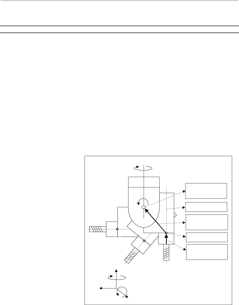
For example, three-dimensional handle feed is possible in a machine
configuration in which the center of rotation of the first axis is identical
to that of the second but the center of rotation of the spindle is not
identical to that of the first axis, such as that shown in the figure below.
Spindle center
Spindle center compensation vector
Parameter No. 7520
Center of rotation of axis C =
Center of rotation of axis B
X
Z
Y
C
B
Tool holder offset
Parameter No. 7548
C
B
Center of rotation of spindle
Fig. 3.5.1(a) Machine configuration in which the center of rotation of the
spindle differs from that of the first axis
Contents Summary of 15i/150i - Model B Connection manual (Function)
- Page 1CONNECTION MANUAL (FUNCTION) B-63783EN-1/01
- Page 2Ȧ No part of this manual may be reproduced in any form. Ȧ All specifications and designs are subject to change without notice. The export of this product is subject to the authorization of the government of the country from where the product is exported. In this manual we have tried as much as possi
- Page 3B-63783EN-1/01 DEFINITION OF WARNING, CAUTION, AND NOTE DEFINITION OF WARNING, CAUTION, AND NOTE This manual includes safety precautions for protecting the user and preventing damage to the machine. Precautions are classified into Warning and Caution according to their bearing on safety. Also, suppl
- Page 4
- Page 5B-63783EN-1/01 PREFACE PREFACE Contents of this document This manual describes all the NC functions required to enable machine tool builders to design their CNC machine tools. The following items are explained for each function. 1. General Describes feature of the function. Refer to Operator's manua
- Page 6PREFACE B-63783EN-1/01 Signal description Relation of interface signals among the CNC, the PMC and the machine tool is shown below: G000 - X000 - CNC F000 - PMC Y000 - Machine tool NOTE For the signals, a single data number is assigned to 8 bits. Each bit has a different meaning. - Expression of sig
- Page 7B-63783EN-1/01 PREFACE Parameter description Parameters are classified by data type as follows : Data type Valid data range Remarks Bit Bit axis 0 or 1 Bit spindle Integer In some parameters, signs are Integer axis 0 to ±999999999 ignored. Integer spindle Real Standard parameter Real axis See settin
- Page 8PREFACE B-63783EN-1/01 Related Manuals for Series 15i/150i- MODEL B The table below lists manuals related to MODEL B of Series 15i and Series 150i. In the table, this manual is marked with an asterisk(*). Table 1 (a) Manuals Related to the Series 15i, 150i Manual name Specification number DESCRIPTIO
- Page 9B-63783EN-1/01 TABLE OF CONTENTS TABLE OF CONTENTS SAFETY PRECAUTIONS .......................................................................... s-1 PREFACE.................................................................................................. p-1 1 AXIS CONTROL...........................
- Page 10TABLE OF CONTENTS B-63783EN-1/01 1.5.4 Servo Warning Details Signal ............................................................................. 153 1.6 SETTINGS RELATED TO COORDINATE SYSTEMS ..............................154 1.6.1 Machine Coordinate System..........................................
- Page 11B-63783EN-1/01 TABLE OF CONTENTS 2.3.2 Stored Stroke Check 1 ......................................................................................... 304 2.3.3 Stroke Check 2..................................................................................................... 308 2.3.4 Stroke Limit
- Page 12TABLE OF CONTENTS B-63783EN-1/01 5.3.3 Single Block ........................................................................................................ 488 5.4 MANUAL ABSOLUTE ON/OFF .................................................................491 5.5 OPTIONAL BLOCK SKIP/ADDITION OF OPTIONA
- Page 13B-63783EN-1/01 TABLE OF CONTENTS 6.17 SPIRAL INTERPOLATION, CONICAL INTERPOLATION ........................602 6.18 NURBS INTERPOLATION ........................................................................605 6.18.1 NURBS Interpolation Additional Functions .........................................
- Page 14TABLE OF CONTENTS B-63783EN-1/01 7.2.3.1 In-position check ..............................................................................................717 7.2.4 Feed Forward in Rapid Traverse ......................................................................... 720 7.2.5 Acceleration/Decelerat
- Page 15B-63783EN-1/01 TABLE OF CONTENTS 10.4.7 Rotary Table Dynamic Fixture Offset ............................................................... 1044 10.4.8 Three-dimensional Cutter Compensation.......................................................... 1051 10.4.8.1 Three-dimensional cutter compensation
- Page 16TABLE OF CONTENTS B-63783EN-1/01 12.1.3 Alarm Display.................................................................................................... 1279 12.1.4 Operator Message Display................................................................................. 1281 12.1.5 Servo Adjustment
- Page 17B-63783EN-1/01 TABLE OF CONTENTS 12.2.8 Editing a Running Program ............................................................................... 1360 12.2.9 DO Signal Output by Soft Key.......................................................................... 1361 12.3 READER/PUNCHER INTERFACE ....
- Page 18
- Page 19B-63783EN-1/01 1.AXIS CONTROL 1 AXIS CONTROL -1-
- Page 201.AXIS CONTROL B-63783EN-1/01 1.1 NUMBER OF CONTROLLED AXES General Series 15i/150i Item Standard Multiaxis specification specification Number of basic controlled axes 3 Extension of the number of 10 maximum 24 maximum controlled axes (total) (including 2 Cs axes) Number of basic simultaneous 2 cont
- Page 21B-63783EN-1/01 1.AXIS CONTROL 1.2 SETTING EACH AXIS 1.2.1 Axis Name General Those axes (including PMC-controlled axes) that are controlled by the CNC must be named. Axis names can be selected from X, Y, Z, A, B, C, U, V, and W (with parameter No. 1020). When parallel axis control, synchronization co
- Page 221.AXIS CONTROL B-63783EN-1/01 Parameter 1020 Program axis name for each axis [Input type] Parameter input [Data type] Integeraxis [Valid data range] 65 - 90 The programmed axis name of each controlled axis is set according to the following table: Axis Setting name X 88 Y 89 Z 90 A 65 B 66 C 67 U 85
- Page 23B-63783EN-1/01 1.AXIS CONTROL 1021 Subscripts of the axis names of parallel, synchronization control, and tandem control axes [Input type] Parameter input [Data type] Integeraxis [Valid data range] 0-9, 65-90 To distinguish the axes controlled in parallel operation mode, synchronization control mode
- Page 241.AXIS CONTROL B-63783EN-1/01 1.2.2 Increment System General The increment system depends on the combination of the least input increment (input increment) and least command increment (output increment). The least input increment is the least increment for the programmed amount of movement. The leas
- Page 25B-63783EN-1/01 1.AXIS CONTROL When bit 0 (IM0) of parameter No. 1013 for increasing the input increment 10 times is set to 1, and a command is issued without specifying the decimal point, each increment system is as indicated in Table 3.2.2(b). Table. 1.2.2 (b) Increment Least input Least command Ma
- Page 261.AXIS CONTROL B-63783EN-1/01 #1 INM Specifies whether the least command increment for the linear axis is metric or in inches. 0: Metric. (The machine is a millimeter machine.) 1: Inches. (The machine is an inch machine.) #7 #6 #5 #4 #3 #2 #1 #0 1006 DIA [Input type] Parameter input [Data type] Bita
- Page 27B-63783EN-1/01 1.AXIS CONTROL #0 ISA #1 ISC #2 ISD #3 ISE Increment system for each axis Increment system #3 ISE #2 ISD #1 ISC #0 ISA IS-A 0 0 0 1 IS-B 0 0 0 0 IS-C 0 0 1 0 IS-D 0 1 0 0 IS-E 1 0 0 0 #7 #6 #5 #4 #3 #2 #1 #0 1013 IM0 [Input type] Parameter input [Data type] Bitaxis #0 IM0 Specifies wh
- Page 281.AXIS CONTROL B-63783EN-1/01 1.2.3 Rotation Axis Specification General Whether an axis is to be set as a linear axis or rotation axis can be specified on an axis-by-axis basis with bit 0 (ROT) of parameter No. 1006. For an axis set as a rotation axis by ROT, the inch/metric conversion function is d
- Page 29B-63783EN-1/01 1.AXIS CONTROL #1 ROS Specifies whether the machine coordinate system used for stroke check and automatic reference position return is linear or rotational. 0: Linear (linear axis) 1: Rotation (rotation axis) For a rotation axis, the machine coordinate system is normalized within the
- Page 301.AXIS CONTROL B-63783EN-1/01 1260 Angular displacement about the rotation axis when the connected motor rotates one turn NOTE After this parameter has been set, the power must be off turned off then back on for the setting to become effective. [Input type] Parameter input [Data type] Realaxis [Unit
- Page 31B-63783EN-1/01 1.AXIS CONTROL 5425 Angular displacement per rotation in rotation-axis pitch error compensation NOTE After this parameter has been set, the power must be off turned off then back on for the setting to become effective. [Input type] Parameter input [Data type] Realaxis [Unit of data] m
- Page 321.AXIS CONTROL B-63783EN-1/01 1.2.4 Controlled Axes Detach General These signals release the specified control axes from control. When attachments are used (such as a detachable rotary table), these signals are selected according to whether the attachments are mounted. The signals can also be used f
- Page 33B-63783EN-1/01 1.AXIS CONTROL Controlled axis detach status signals MDTCH1
- Page 341.AXIS CONTROL B-63783EN-1/01 #7 #6 #5 #4 #3 #2 #1 #0 1005 RMB [Input type] Parameter input [Data type] Bitaxis #7 RMB For each axis, specifies whether the control axis detach signal and setting input RMV (bit 7 of parameter No. 0012) is valid. 0: Invalid. 1: Valid. #7 #6 #5 #4 #3 #2 #1 #0 1009 MCC
- Page 35B-63783EN-1/01 1.AXIS CONTROL Caution CAUTION When a 2-axis or 3-axis amplifier is used, releasing only one axis from control results in the output of SV013 (V ready off). Use 1-axis amplifiers for those axes to be released from control, e.g., by replacing the rotary table. Note NOTE 1 Controlled ax
- Page 361.AXIS CONTROL B-63783EN-1/01 1.2.5 Outputting the Movement State of an Axis General The movement state of each axis can be output to the PMC. Signal Axis moving signals MV1
- Page 37B-63783EN-1/01 1.AXIS CONTROL CAUTION 1 These signals maintain their existing condition during a stop, indicating the direction of the axes' movement before being stopped. 2 In the case of manual handle interrupt and simultaneous automatic and manual operation, the direction depends on the sum of bo
- Page 381.AXIS CONTROL B-63783EN-1/01 1.2.6 Mirror Image General Mirror image can be applied to each axis, either by signals or by parameters (setting input is acceptable). All movement directions are reversed during automatic operation along axes to which a mirror image is applied. X B A B’ Y 0 When MI1 si
- Page 39B-63783EN-1/01 1.AXIS CONTROL Mirror image check signal MMI1
- Page 401.AXIS CONTROL B-63783EN-1/01 Caution CAUTION 1 When programmable mirror image and ordinary mirror image are specified at the same time, programmable mirror image is applied first. 2 No programmable mirror image affects mirror image check signals. 3 Even when the mirror image is applied, commands wh
- Page 41B-63783EN-1/01 1.AXIS CONTROL 1.2.7 Follow-up General If the machine moves in the state in which position control on controlled axes is disabled (during servo-off, emergency stop, or servo alarm), feedback pulses are accumulated in the error counter. The CNC reflects the machine movement correspondi
- Page 421.AXIS CONTROL B-63783EN-1/01 Parameter #7 #6 #5 #4 #3 #2 #1 #0 1800 FVF [Input type] Parameter input [Data type] Bit #2 FVF Specifies whether to perform follow-up in the servo-off mode. 0: Does not perform follow-up (mechanical clamp in the servo off mode). 1: Performs follow-up (mechanical handle
- Page 43B-63783EN-1/01 1.AXIS CONTROL 1.2.8 Servo Off (Mechanical handle) General Place the controlled axes in the servo off state; that is, they stop the current to the servo motor, which disables position control. However, the position detection feature functions continuously, so the current position is n
- Page 441.AXIS CONTROL B-63783EN-1/01 Parameter #7 #6 #5 #4 #3 #2 #1 #0 1802 SVF [Input type] Parameter input [Data type] Bitaxis #1 SVF Specifies whether to validate the servo off signal. 0: Does not validate the servo off signal. 1: Validates the servo off signal. Caution CAUTION 1 In general, interlock i
- Page 45B-63783EN-1/01 1.AXIS CONTROL 1.2.9 Position Switch General Position switch signals can be output to the PMC while the machine coordinates along a controlled axes are within a specified ranges. Using parameters, specify arbitrary controlled axes and machine coordinate operating ranges for which posi
- Page 461.AXIS CONTROL B-63783EN-1/01 - Setting the correspondence between position switch signals and controlled axes 5270 Controlled axis for which the tenth position switch function is performed (PSWA01) 5271 Controlled axis for which the 2-nd position switch function is performed (PSWA02) 5272 Controlle
- Page 47B-63783EN-1/01 1.AXIS CONTROL - Setting of position switch operating ranges - Maximum value 5280 Maximum value of the operating range of the 1-st position switch (PSW101) 5281 Maximum value of the operating range of the 2-nd position switch (PSW102) 5282 Maximum value of the operating range of the 3
- Page 481.AXIS CONTROL B-63783EN-1/01 - Minimum value 5290 Minimum value of the operating range of the 1-st position switch (PSW201) 5291 Minimum value of the operating range of the 2-nd position switch (PSW202) 5292 Minimum value of the operating range of the 3-rd position switch (PSW203) 5293 Minimum valu
- Page 49B-63783EN-1/01 1.AXIS CONTROL 1.2.10 Vertical Axis Drop Prevention Function Overview If the machine is brought to an emergency stop and the power for a servo motor is turned off, the machine applies a brake to the axis corresponding to the stopped servo motor. If the power for the servo motor of a v
- Page 501.AXIS CONTROL B-63783EN-1/01 Limitations If a vertical axis and a nonvertical axis are connected to the same multiaxis amplifier, the multiaxis amplifier turns off the power for the vertical axis at the same time that the power for the nonvertical axis is turned off. This prevents the vertical axis
- Page 51B-63783EN-1/01 1.AXIS CONTROL 1.3 ERROR COMPENSATION 1.3.1 Stored Pitch Error Compensation Overview If pitch error compensation data is specified, pitch errors of each axis can be compensated in detection unit per axis. Pitch error compensation data is set for each compensation position at the inter
- Page 521.AXIS CONTROL B-63783EN-1/01 Procedure for displaying and setting the pitch error compensation data 1 Set the following parameters: - Number of the pitch error compensation position at the reference position (for each axis): Parameter(No.5420) - Number of the pitch error compensation position havin
- Page 53B-63783EN-1/01 1.AXIS CONTROL Explanation - Specifying the compensation position To assign the compensation positions for each axis, specify the positive direction or the negative direction in reference to the compensation position No. of the reference position. If the machine stroke exceeds the spe
- Page 541.AXIS CONTROL B-63783EN-1/01 Therefore, set the parameters as follows: Parameter Setting value 5420 : Compensation number for the reference position 40 5421 : Smallest compensation position number 33 5422 : Largest compensation position number 56 5423 : Compensation magnification 1 The compensation
- Page 55B-63783EN-1/01 1.AXIS CONTROL Reference position 0.0 45.0 315.0 (61) (68) (62) (67) (+) 90.0 270.0 (63) (66) (64) (65) 135.0 225.0 Compensation values are output at the 180.0 positions indicated by . Therefore, set the parameters as follows: Parameter Setting 5420: Compensation No. of reference posi
- Page 561.AXIS CONTROL B-63783EN-1/01 Parameter 5420 Number of pitch error compensation point of reference position for each axis NOTE After this parameter has been set, the power must be off turned off then back on for the setting to become effective. [Input type] Parameter input [Data type] Integeraxis [V
- Page 57B-63783EN-1/01 1.AXIS CONTROL 5421 Number of pitch error compensation point with the largest negative value for each axis NOTE After this parameter has been set, the power must be off turned off then back on for the setting to become effective. [Input type] Parameter input [Data type] Integeraxis [V
- Page 581.AXIS CONTROL B-63783EN-1/01 5422 Number of pitch error compensation point with the largest positive value for each axis NOTE After this parameter has been set, the power must be off turned off then back on for the setting to become effective. [Input type] Parameter input [Data type] Integeraxis [V
- Page 59B-63783EN-1/01 1.AXIS CONTROL 5424 Interval of pitch error compensation points for each axis NOTE After this parameter has been set, the power must be off turned off then back on for the setting to become effective. [Input type] Parameter input [Data type] Realaxis [Unit of data] mm, inch, degree (m
- Page 601.AXIS CONTROL B-63783EN-1/01 5425 Angular displacement per rotation in rotation-axis pitch error compensation NOTE After this parameter has been set, the power must be off turned off then back on for the setting to become effective. [Input type] Parameter input [Data type] Realaxis [Unit of data] m
- Page 61B-63783EN-1/01 1.AXIS CONTROL Caution CAUTION - Compensation value range Compensation values can be set within the range from -7 x compensation magnification (detection unit) to +7 x compensation magnification (detection unit). The compensation magnification can be set for each axis within the range
- Page 621.AXIS CONTROL B-63783EN-1/01 1.3.2 Backlash Compensation General - Backlash compensation Function for compensating for lost motion on the machine. Set a compensation value in parameter No. 1851, in detection units from 0 to ±9999 pulses for each axis. - Backlash compensation for each rapid traverse
- Page 63B-63783EN-1/01 1.AXIS CONTROL Procedures for measuring the backlash compensation amounts during cutting feed and rapid traverse - Backlash compensation amount during cutting feed 1 Set the backlash compensation amount during cutting feed (parameter No. 1851) to "0." 2 Move the machine to the measure
- Page 641.AXIS CONTROL B-63783EN-1/01 - Backlash compensation amount during rapid traverse 1 Set the backlash compensation amount during rapid traverse (parameter No. 1849) to "0." 2 Move the machine to the measurement point by rapid traverse. Mount a dial gauge and set the pointer to "0." G00 G90 X0 ; X100
- Page 65B-63783EN-1/01 1.AXIS CONTROL Operation examples In these examples, the following are assumed: Backlash compensation amount during cutting feed A = 40 Backlash compensation amount during rapid traverse B = 20 α = (A - B)/2 = 10 Initial backlash direction = Minus • = Machine position. 1 Reference pos
- Page 661.AXIS CONTROL B-63783EN-1/01 4 Rapid traverse followed by rapid traverse in the opposite direction G00 X100.0 ; Current compensation amount=-B=-20 Accumulated compensation amount=10 0 100 200 300 Rapid traverse 10 5 Rapid traverse followed by cutting feed in the opposite direction G01 X200.0 Ff; Cu
- Page 67B-63783EN-1/01 1.AXIS CONTROL 8 Cutting feed followed by rapid traverse in the same direction G00 X100.0 ; Current compensation amount=-(-α)=10 Accumulated compensation amount=10 0 100 200 300 Rapid traverse 10 9 Rapid traverse followed by cutting feed in the same direction G00 X0 ; Current compensa
- Page 681.AXIS CONTROL B-63783EN-1/01 1849 Backlash compensation amount used for rapid traverse for each axis [Input type] Parameter input [Data type] Integeraxis [Unit of data] detection unit [Valid data range] -9999 - 9999 Set the backlash compensation amount used in rapid traverse for each axis. (This pa
- Page 69B-63783EN-1/01 1.AXIS CONTROL 1.3.3 Straightness Compensation General For a machine tool with a long stroke, deviations in straightness between axes may deteriorate machining accuracy. For this reason, when an axis moves, other axes are compensated in detection units to improve straightness. This im
- Page 701.AXIS CONTROL B-63783EN-1/01 Parameter 5481 Axis number of straightness compensation move axis 1 5482 Axis number of straightness compensation move axis 2 5483 Axis number of straightness compensation move axis 3 [Input type] Parameter input [Data type] Integer [Valid data range] From 1 through the
- Page 71B-63783EN-1/01 1.AXIS CONTROL 5511 Compensation point number a of straightness compensation move axis 2 5512 Compensation point number b of straightness compensation move axis 2 5513 Compensation point number c of straightness compensation move axis 2 5514 Compensation point number d of straightness
- Page 721.AXIS CONTROL B-63783EN-1/01 5571 Compensation corresponding to compensation point number a of move axis 3 5572 Compensation corresponding to compensation point number b of move axis 3 5573 Compensation corresponding to compensation point number c of move axis 3 5574 Compensation corresponding to c
- Page 73B-63783EN-1/01 1.AXIS CONTROL Note NOTE 1 The straightness compensation function can be used after a moving axis and its compensation axis have returned to the reference position. 2 After setting parameters for straightness compensation, be sure to turn off the NC power. 3 Set parameters for straigh
- Page 741.AXIS CONTROL B-63783EN-1/01 1.3.4 Interpolated Straightness Compensation Compensation data, which is set using 128-point straightness compensation data, is divided into parts at equal intervals in each compensation point interval and output. Explanation - Compensation methods With the 128-point st
- Page 75B-63783EN-1/01 1.AXIS CONTROL Parameter #7 #6 #5 #4 #3 #2 #1 #0 5426 IPC [Input type] Parameter input [Data type] Bitaxis #6 IPC Specifies whether to use the interpolating straightness compensation function. 0: Do not use. 1: Use. This parameter is valid only when it is set for those move axes (cont
- Page 761.AXIS CONTROL B-63783EN-1/01 Warning WARNING 1 If the feedrate is high, multiple compensation pulses may be output at one time depending on the straightness compensation amount. 2 To use this function, the stored pitch error compensation option is required in addition to this function option. 3 The
- Page 77B-63783EN-1/01 1.AXIS CONTROL 1.3.5 128 Straightness Compensation Points Overview In straightness compensation, compensation data is set as the compensation amounts at the individual compensation points, in the same way as in stored pitch error compensation. This enables fine compensation. Up to fiv
- Page 781.AXIS CONTROL B-63783EN-1/01 The following relationships hold: i δ = φ + (γ-α) ii π = φ + (β-α) and π, δ are automatically calculated from α, β, γ, and φ. Therefore, no parameters need be set for them. - Display and setting of straightness compensation data The setting of 128-point straightness com
- Page 79B-63783EN-1/01 1.AXIS CONTROL Examples The following explains the method of setting parameters for the travel and compensation axes, as well as effective magnifications. The parameters for travel and compensation axes can be set as follows. 1) A single compensation axis can be set for a single trave
- Page 801.AXIS CONTROL B-63783EN-1/01 As described above, a compensation axis can be set as a travel axis. If a compensation axis is set as such, the amount of travel due to compensation on the travel axis is not subject to compensation. 4) A single compensation axis cannot have two or more travel axes. Tab
- Page 81B-63783EN-1/01 1.AXIS CONTROL 5494 Axis number of compensation axis 4 for straightness compensation move axis 4 5495 Axis number of compensation axis 5 for straightness compensation move axis 5 [Input type] Parameter input [Data type] Integer [Valid data range] From 1 through the number of controlle
- Page 821.AXIS CONTROL B-63783EN-1/01 5593 Straightness compensation multiplier of move axis 3 5594 Straightness compensation multiplier of move axis 4 5595 Straightness compensation multiplier of move axis 5 [Input type] Parameter input [Data type] Integer [Valid data range] 0 - 100 Specify a straightness
- Page 83B-63783EN-1/01 1.AXIS CONTROL Caution CAUTION 1 If the feedrate is high, multiple compensation pulses may be output at the same time depending on the straightness compensation amount. 2 To use this function, the stored pitch error compensation option is required in addition to this function option.
- Page 841.AXIS CONTROL B-63783EN-1/01 1.3.6 Interpolated Pitch Error Compensation Overview In stored pitch error compensation, the pitch error compensation pulse at each pitch error compensation point is output in the interval between that point and the next compensation point, as shown in the figure below.
- Page 85B-63783EN-1/01 1.AXIS CONTROL - Number of the most distant pitch error compensation point on the side of each axis No.5421 - Number of the most distant pitch error compensation point on the + side of each axis No.5422 - Pitch error compensation magnification for each axis No.5423 - Pitch error compe
- Page 861.AXIS CONTROL B-63783EN-1/01 1.3.7 Cyclic Second Pitch Error Compensation Overview When a rotary table is rotated using a gear, there are two cycles of the occurrence of pitch errors: One cycle is the same as that of the rotation of the rotary table while the other is the same as that of the rotati
- Page 87B-63783EN-1/01 1.AXIS CONTROL Although a rotary table is used as an example here, cyclic second pitch error compensation can be used in the same way when the machine is moved along a linear axis using a gear. For example, in a configuration such as that shown in Fig. 1.3.7 (c), stored pitch error co
- Page 881.AXIS CONTROL B-63783EN-1/01 - Pitch error with a 360° cycle 180° ε A 0° 360° 20° Fig. 1.3.7 (e) - Pitch error after superimposition in portion A Pitch error with the cycle of the rotation of the gear ε : Pitch error in portion A ε A Fig. 1.3.7 (f) Synchronous Second Pitch Error The above figure (F
- Page 89B-63783EN-1/01 1.AXIS CONTROL Parameter 5430 Number of the farthest second cyclical pitch error compensation point in the negative direction for each axis [Input type] Parameter input [Data type] Integeraxis [Valid data range] From 0 through 1279 or from 0 through 3071 depending on the number of con
- Page 901.AXIS CONTROL B-63783EN-1/01 5433 Magnification for second cyclical pitch error compensation for each axis [Input type] Parameter input [Data type] Integeraxis [Valid data range] 0 - 100 Set a magnification for second cyclical pitch error compensation for each axis. When 1 is set as the magnificati
- Page 91B-63783EN-1/01 1.AXIS CONTROL 1.3.8 Gradient Compensation Overview By compensating for those errors in tools such as feed screws that depend on the position of the machine system in detection units, machining precision can be improved and mechanical life can be prolonged. In gradient compensation, t
- Page 921.AXIS CONTROL B-63783EN-1/01 Gradient compensation parameters must be set. a, b, c, d : Compensation point numbers. (Pitch error compensation point numbers are used. Parameters Nos. 5461 to 5464) α, β, γ, ε : Compensation amounts at compensation points a, b, c, and d (parameters Nos. 5471 to 5474)
- Page 93B-63783EN-1/01 1.AXIS CONTROL Alarm and message Number Message Contents PW0102 ILLEGAL PARAMETER (I-COMP.) The parameter for setting slope compensation is incorrect. This alarm occurs in the following cases: • When the number of pitch error compensation points on the axis on which slope compensation
- Page 941.AXIS CONTROL B-63783EN-1/01 1.3.9 Bidirectional Pitch Error Compensation Overview In bidirectional pitch error compensation, different pitch error compensation amounts can be set for travel in the positive direction and that in the negative direction, so that pitch error compensation can be perfor
- Page 95B-63783EN-1/01 1.AXIS CONTROL ParameterNo.5421 ParameterNo.5422 ↓ ↓ Set of pitch error compensation data for Set of n data items the positive direction ParameterNo.5427 ↓ Set of pitch error compensation data Set of n data items for the negative direction ↑ The pitch error compensation data numbers i
- Page 961.AXIS CONTROL B-63783EN-1/01 Table 1.3.9 (b) Positive-direction pitch error data Compensation 20 21 22 23 24 25 26 27 point number Compensation -1 +1 0 +1 +1 +2 -1 -1 amount to be set As pitch error data, always set incremental values as viewed in the negative direction (direction toward the left i
- Page 97B-63783EN-1/01 1.AXIS CONTROL - Compensation example If, in the setting example given in the previous section, the machine moves from 0.0 to 40.0, from 40.0 to -40.0, and from -40.0 to 0.0 for a manual reference position return, pitch error compensation pulses are output as follows: Machine coordina
- Page 981.AXIS CONTROL B-63783EN-1/01 Parameter #7 #6 #5 #4 #3 #2 #1 #0 5426 BDP [Input type] Parameter input [Data type] Bitaxis #5 BDP Specifies whether to use bidirectional pitch error compensation. 0: Do not use. 1: Use. 5420 Number of pitch error compensation point of reference position for each axis [
- Page 99B-63783EN-1/01 1.AXIS CONTROL 5422 Number of pitch error compensation point with the largest positive value for each axis [Input type] Parameter input [Data type] Integeraxis [Valid data range] From 0 through 1279 (or from 10000 through 11279) or from 0 through 3071 (or from 10000 through 13071) dep
- Page 1001.AXIS CONTROL B-63783EN-1/01 5425 Angular displacement per rotation in rotation-axis pitch error compensation [Input type] Parameter input [Data type] Realaxis [Unit of data] mm, inch, degree (machine unit) [Minimum unit of data] Depend on the increment system of the applied axis [Valid data range]
- Page 101B-63783EN-1/01 1.AXIS CONTROL 5428 Pitch error compensation value at the reference position when a movement is made to the reference position in the direction opposite to the reference position return direction [Input type] Parameter input [Data type] Integeraxis [Unit of data] detection unit [Valid
- Page 1021.AXIS CONTROL B-63783EN-1/01 1.3.10 Nano Interpolation Type Error Compensation Overview This function enables the servo output of interpolation-type pitch error compensation, third-dimensional error compensation, and interpolation-type straightness compensation to be performed with a detection unit
- Page 103B-63783EN-1/01 1.AXIS CONTROL 1.3.11 Smooth Backlash Compensation Overview Ordinary backlash compensation outputs all backlash compensation pulses at a point where the direction of axis movement is reversed. (Fig. 1.3.11(a)) (Direction reversed) Axis movement direction Total amount of backlash compe
- Page 1041.AXIS CONTROL B-63783EN-1/01 - When ‘Smooth backlash compensation’ is required Usually, relationship between motor position and actual machine position can be shown as Fig.1.3.11(c). In this case, conventional backlash compensation (compensation pulse is outputted at once when direction changes) is
- Page 105B-63783EN-1/01 1.AXIS CONTROL In this case, when we apply current backlash compensation, compensation becomes too much just after the direction change. With circular cutting, cutting path will be shown in Fig.1.3.11(e). Backlash compensation is too much at this point Fig. 1.3.11(e) In order to avoid
- Page 1061.AXIS CONTROL B-63783EN-1/01 - Second-stage backlash compensation output The output of second-stage backlash compensation begins at distance L1 from a point where the direction of axis movement is reversed and ends at distance L2 from that point. The total amount (B2) of backlash compensation perfo
- Page 107B-63783EN-1/01 1.AXIS CONTROL #7 #6 #5 #4 #3 #2 #1 #0 1804 RBK [Input type] Parameter input [Unit of data] Bit axis NOTE Once this parameter is re-set, it is necessary to switch the power off and on again. #6 RBK Specifies whether to perform cutting-/rapid traverse-specific backlash compensation as
- Page 1081.AXIS CONTROL B-63783EN-1/01 1846 Distance at which the second stage of smooth backlash compensation begins [Input type] Parameter input [Unit of data] Integer axis [Valid data range] Detection unit [Valid data range] 0 to 999999999 This parameter specifies the distance where the second stage of sm
- Page 109B-63783EN-1/01 1.AXIS CONTROL 1849 Amount of rapid traverse backlash compensation for an individual axis [Input type] Parameter input [Unit of data] Integer axis [Valid data range] Detection unit [Valid data range] -9999 to 9999 This parameter specifies the amount of rapid traverse backlash compensa
- Page 1101.AXIS CONTROL B-63783EN-1/01 1.3.12 Addition of 5000 Pitch Error Compensation Points Overview This function can add 5000 points for stored, interpolation-type, bidirectional, and cyclic second pitch error compensation. The added points are used as compensation point numbers 5000 to 9999. The existi
- Page 111B-63783EN-1/01 1.AXIS CONTROL Caution CAUTION 1 Stored pitch error compensation cannot be used across a standard compensation point (numbers 0 to 1279 or, in a system having more than 10 controlled axes, numbers 0 to 3071) and an expansion compensation point (numbers 5000 to 9999) for the same axis.
- Page 1121.AXIS CONTROL B-63783EN-1/01 1.3.13 Thermal Growth Compensation along Tool Vector Outline The thermal growth compensation along tool vector, in added to the compensation is input by using the external data input signal. The thermal growth compensation along tool vector is applied with following 5 t
- Page 113B-63783EN-1/01 1.AXIS CONTROL Basic Procedure Thermal growth compensation is input by following the method. 1. The PMC drives the start signal THML high and sets the Thermal growth compensation data signals THD00 to THD15. 2. The PMC then drives the strobe signal THSTB high. 3. When THSTB goes high,
- Page 1141.AXIS CONTROL B-63783EN-1/01 D : Thermal growth along tool axis data ( G178 to G179 ) ε : Amount of thermal growth compensation along tool axis (1) When data is positive( D > 0 : When the tool length is an extension ) +Z εx ( along the X axis ) εz ( along the Z axis ) +X ε D ( Direction of thermal
- Page 115B-63783EN-1/01 1.AXIS CONTROL Signals Thermal growth compensation start signal THML
- Page 1161.AXIS CONTROL B-63783EN-1/01 Signals address #7 #6 #5 #4 #3 #2 #1 #0 G161 THML F179 MTHML G161 THSTB F170 THREND G178 THD07 THD06 THD05 THD04 THD03 THD02 THD01 THD00 G179 THD15 THD14 THD13 THD12 THD11 THD10 THD09 THD08 Parameter 6080 Rotation axis for three-dimensional cutter compensation and so fo
- Page 117B-63783EN-1/01 1.AXIS CONTROL 6084 Angle of inclination for the rotation axis for three-dimensional cutter compensation and so forth (first group) [Input type] Parameter input [Data type] Real [Unit of data] degree [Minimum unit of data] Depend on the increment system of the reference axis [Valid da
- Page 1181.AXIS CONTROL B-63783EN-1/01 6089 Angle of inclination for the rotation axis for three-dimensional cutter compensation and so forth (second group) [Input type] Parameter input [Data type] Real [Unit of data] degree [Minimum unit of data]Depend on the increment system of the reference axis [Valid da
- Page 119B-63783EN-1/01 1.AXIS CONTROL -The rotation axis rotates about an axis that perpendicularly intersects the plane formed by linear axis 1 and linear axis 2. -When the rotation axis rotates from the positive direction of linear axis 1 to the positive direction of linear axis 2, the rotation axis is sa
- Page 1201.AXIS CONTROL B-63783EN-1/01 6104 Reference angle for the rotation axis for three-dimensional cutter compensation and so forth (first group) 6105 Reference angle for the rotation axis for three-dimensional cutter compensation and so forth (second group) [Input type] Parameter input [Data type] Real
- Page 121B-63783EN-1/01 1.AXIS CONTROL Parameter Nos. 6106 to 6107 The direction of a compensation vector is set by setting an angular displacement (RA, RB) from the direction of linear axis 3. RA: Rotation is performed in the plane formed by linear axis 2 and linear axis 3. When rotation is performed from t
- Page 1221.AXIS CONTROL B-63783EN-1/01 7517 Offset value for angular displacement of a rotation axis [Input type] Parameter input [Data type] Realaxis [Unit of data] degree [Minimum unit of data] Depend on the increment system of the applied axis [Valid data range] 9 digit of minimum unit of data (refer to s
- Page 123B-63783EN-1/01 1.AXIS CONTROL #3 HPE Specifies the actual detection unit for the output of interpolation-type pitch error compensation, third-dimensional error compensation interpolation-type straightness compensation, and thermal growth compensation along tool vector as follows: 0: Detection unit 1
- Page 1241.AXIS CONTROL B-63783EN-1/01 CAUTION 11 If detaching of any axis is done by the axis detaching signal, the thermal growth compensation must be cancelled. 12 Parameter No.6080 to No.6089, No.6104 to No.6107, No.7517, and No.7518 must not be changed, while this function is valid. 13 Synchronous contr
- Page 125B-63783EN-1/01 1.AXIS CONTROL 1.4 THREE-DIMENSIONAL ERROR COMPENSATION Overview In ordinary pitch error compensation, compensation is applied to a specified compensation axis (single axis) using the position information for that axis. For example, pitch error compensation is applied to the X-axis us
- Page 1261.AXIS CONTROL B-63783EN-1/01 individual axes at the individual vertexes be Cnx, Cny, and CNz (where n is a number between 1 and 8). Let the interior division ratio on the X-axis at P be x. Here, x is standardized in the range of 0 to 1 as follows: Cx = C1x ⋅ (1 − x )(1 − y )(1 − z ) + C 2 x ⋅ x (1
- Page 127B-63783EN-1/01 1.AXIS CONTROL - Input/output format The three-dimensional error compensation screen allows output/input (punching/reading) of compensation data. The command format is as follows: N......A1P....A2P....A3P.... N...... :Data number (compensation point number + 100000) as represented wit
- Page 1281.AXIS CONTROL B-63783EN-1/01 Three-dimensional error compensation screen Compensation amount Compensation amount (current) - Compensation amount Compensation point numbers are displayed, as well as compensation data for the individual compensation axes. - Compensation amount (current) The error com
- Page 129B-63783EN-1/01 1.AXIS CONTROL - Punching of compensation data (1) Place the system in EDIT mode. (2) Click soft key [Punch]. (3) Enter the file number and name as required, according to the specifications of the output device. (4) Click soft key [Three-dimensional error compensation]. (5) The punchi
- Page 1301.AXIS CONTROL B-63783EN-1/01 5446 Number of the three-dimensional error compensation point at the reference position (1-st axis) 5447 Number of the three-dimensional error compensation point at the reference position (2-nd axis) 5448 Number of the three-dimensional error compensation point at the r
- Page 131B-63783EN-1/01 1.AXIS CONTROL Caution CAUTION The setting of compensation data using programmable parameter input (G10L51) must be specified in canned cycle cancel mode, as with ordinary programmable parameter input (G10L50). (If the setting of data is specified in canned cycle mode, a cyclic operat
- Page 1321.AXIS CONTROL B-63783EN-1/01 1.5 SETTINGS RELATED TO SERVO CONTROLLED AXES Typical units handled through the servo interface include: - Digital controlled AC servo motor - Motor feedback: Serial coder (1) 1,000,000 pulses/rev absolute pulse coder (2) 65,536 pulses/rev absolute pulse coder (3) 10,00
- Page 133B-63783EN-1/01 1.AXIS CONTROL 1.5.1 Servo Parameter Overview This section explains the main servo parameters. For an explanation of servo parameters not mentioned here, refer to the "AC Servo Motor αi series Parameter Manual (B-65270EN)". - Command multiply (CMR), detection multiply (DMR), and refer
- Page 1341.AXIS CONTROL B-63783EN-1/01 Parameter #7 #6 #5 #4 #3 #2 #1 #0 1800 IVO SAK CIN CCI RFW FVF CVR [Input type] Parameter input [Data type] Bit #1 CVR Specifies whether to issue a servo alarm if velocity control ready signal VRDY turns on before position control ready signal PRDY turns on. 0: Does not
- Page 135B-63783EN-1/01 1.AXIS CONTROL #4 CCI Specifies the value to be used as the effective area during cutting feed (cutting-feed effective area). 0: Uses parameter 1826, which is also used for rapid traverse. 1: Uses parameter 1838, which is used only for cutting feed. When a positioning block is specifi
- Page 1361.AXIS CONTROL B-63783EN-1/01 #7 IVO Specifies whether to release the emergency stop state when an emergency stop occurs with the VRDY OFF alarm ignore signal being 1. 0: Does not release the emergency stop state until the VRDY OFF alarm ignore signal changes to 0. 1: Releases the emergency stop sta
- Page 137B-63783EN-1/01 1.AXIS CONTROL #1 DGP Specifies whether to set the digital servo parameters specific to the motor at power-on. 0: Sets the digital servo parameters specific to the motor. 1: Does not set the digital servo parameters specific to the motor. When this bit is set to 0 after the motor type
- Page 1381.AXIS CONTROL B-63783EN-1/01 #4 APZ Indicates whether relative positioning of the machine position and absolute-position detector is complete when an absolute-position detector (absolute pulse coder) is used as the position detector. 0: Not complete 1: Complete When an absolute-position detector is
- Page 139B-63783EN-1/01 1.AXIS CONTROL #7 ACM Specify whether to use an optional command multiplication factor 1/N. 0: Does not use the factor. 1: Uses the factor. This bit is effective only when an optional command multiplication factor option is provided. 1820 Command multiplier for each axis (CMR) [Input
- Page 1401.AXIS CONTROL B-63783EN-1/01 1825 Servo loop gain for each axis [Input type] Parameter input [Data type] Integeraxis [Unit of data] 0.01/sec [Valid data range] 1 - 9999 Specify the position control loop gain for each axis. For a machine which performs linear or circular interpolation (cutting), spe
- Page 141B-63783EN-1/01 1.AXIS CONTROL 1829 Positioning deviation limit for each axis when it is stopped [Input type] Parameter input [Data type] Integeraxis [Unit of data] detection unit [Valid data range] 0 - 99999999 Specify the positioning deviation limit for each axis when it is stopped. If the position
- Page 1421.AXIS CONTROL B-63783EN-1/01 1837 Positioning deviation limit while the tool is moving in the rigid tapping mode [Input type] Parameter input [Data type] Integeraxis [Unit of data] detection unit [Valid data range] 0 - 99999999 Specify the positioning deviation limit for a drilling axis while the t
- Page 143B-63783EN-1/01 1.AXIS CONTROL 1849 Backlash compensation amount used for rapid traverse for each axis [Input type] Parameter input [Data type] Integeraxis [Unit of data] detection unit [Valid data range] -9999 - 9999 Set the backlash compensation amount used in rapid traverse for each axis. (This pa
- Page 1441.AXIS CONTROL B-63783EN-1/01 1851 Backlash compensation for each axis [Input type] Parameter input [Data type] Integeraxis [Unit of data] detection unit [Valid data range] -9999 - 9999 Specify the backlash compensation for each axis. When an axis moves in the direction opposite to the reference pos
- Page 145B-63783EN-1/01 1.AXIS CONTROL 1.5.2 Absolute Position Detection Overview Even after the CNC is turned off, the pulse coder, which is backed up by a battery, retains the position. This eliminates the need to perform a reference position return when the CNC is turned on. Signal Absolute position detec
- Page 1461.AXIS CONTROL B-63783EN-1/01 Parameter #7 #6 #5 #4 #3 #2 #1 #0 1815 APC APZ [Input type] Parameter input [Data type] Bitaxis NOTE If this parameter bit is changed, the power must be turned off and back on for the change to take effect. #4 APZ If an absolute-position detector (absolute-pulse coder)
- Page 147B-63783EN-1/01 1.AXIS CONTROL Alarm and message Number Message Contents OT0032 NEED ZRN(ABS PCDR) The reference position and the absolute pulse coder counter value do not match. Another alarm may be issued together with this alarm. Should this occur, it is necessary to apply countermeasures for the
- Page 1481.AXIS CONTROL B-63783EN-1/01 1.5.3 FSSB Setting General Connecting the CNC control section to servo amplifiers via a high- speed serial bus (FANUC Serial Servo Bus, or FSSB), which uses only one fiber optics cable, can significantly reduce the amount of cabling in machine tool electrical sections.
- Page 149B-63783EN-1/01 1.AXIS CONTROL Explanation - Slave In an FSSB-based system, a fiber optics cable is used to connect the CNC to servo amplifiers and pulse modules. These amplifiers and pulse modules are called slaves. The two-axis amplifier consists of two slaves, and the three-axis amplifier consists
- Page 1501.AXIS CONTROL B-63783EN-1/01 - Default setting If the power is turned on when 0 is set for both parameters FMD (bit 0 of No. 1090) and ASE (bit 1 of No. 1090) because of, for example, parameter initialization, default setting is performed. With default setting, the servo axis numbers (parameter No.
- Page 151B-63783EN-1/01 1.AXIS CONTROL - Automatic setting When 0 is set for both parameters FMD (bit 0 of No. 1090) and ASE (bit 1 of No. 1090), automatic setting can be performed from the FSSB setting screen. Perform automatic setting from the FSSB setting screen, by applying the following procedure: 1 On
- Page 1521.AXIS CONTROL B-63783EN-1/01 - Manual setting After 1 is set for parameter FMD (bit 0 of No. 1090) or after automatic setting is performed (1 is set for parameter ASE (bit 1 of No. 1090), FSSB setting parameter Nos. 1023, 1027, 1028, 1080 to 1089, and 1092 to 1097 can be set directly through MDI in
- Page 153B-63783EN-1/01 1.AXIS CONTROL FSSB data display The FSSB setting screen displays FSSB-based amplifier and axis information. This information can also be specified by the operator. 1 Press the
function key. 2 To display [FSSB], press the next menu page key several times. 3 Pressing the [FSSB - Page 1541.AXIS CONTROL B-63783EN-1/01 • AMPLIFIER The amplifier type display consists of the letter A, which stands for "amplifier", a number that indicates the placing of the amplifier, as counted from that nearest to the CNC, and a letter such as L (first axis), M (second axis) or N (third axis) indicatin
- Page 155B-63783EN-1/01 1.AXIS CONTROL - Axis setting screen The axis setting screen displays the information shown below: Fig. 1.5.3 (e) The axis setting screen displays the following items: • AXIS NO. This item is the placing of the NC controlled axis. • NAME This item indicates the name of the correspondi
- Page 1561.AXIS CONTROL B-63783EN-1/01 • TNDM This item is the number specified in parameter No. 1097. Consecutive odd and even numbers are displayed for the master and slave axes for tandem control. • EGB The values set for parameter No. 1096 are displayed. Consecutive odd and even numbers are displayed for
- Page 157B-63783EN-1/01 1.AXIS CONTROL FSSB data setting procedure On an FSSB setting screen (other than the amplifier maintenance screen), pressing the [(OPRT)] soft key displays the following soft keys: Fig. 1.5.3 (g) To enter data, place the machine in MDI mode or the emergency stop state, position the cu
- Page 1581.AXIS CONTROL B-63783EN-1/01 - Axis setting screen On the axis setting screen, the following items can be specified: • M1 : connector number for pulse module 1 For an axis that uses pulse module 1, enter a connector number using a number in the range of between 1 and the maximum number of axes for
- Page 159B-63783EN-1/01 1.AXIS CONTROL • A duplicate value is specified for M2. • A duplicate value is specified for SPOS. • A duplicate value is specified for CS. • A duplicate value is specified for TNDM. • An invalid master/slave axis pair is specified for TNDM. • A duplicate value is specified for EGB. •
- Page 1601.AXIS CONTROL B-63783EN-1/01 Parameter 1080 Address conversion table value (ATR) for slave 1 1081 Address conversion table value (ATR) for slave 2 1082 Address conversion table value (ATR) for slave 3 1083 Address conversion table value (ATR) for slave 4 1084 Address conversion table value (ATR) fo
- Page 161B-63783EN-1/01 1.AXIS CONTROL NOTE 1 When using the electronic gear box (EGB) function Although EGB and dummy axes do not require amplifiers, assume that they are connected to dummy amplifiers. Thus, as the address conversion table value for an non-existing slave, set the value equal to the setting
- Page 1621.AXIS CONTROL B-63783EN-1/01 #7 #6 #5 #4 #3 #2 #1 #0 1092 DSP [Input type] Parameter input [Data type] Bitaxis #0 DSP Usually, do not directly enter any value, because this parameter is specified on the FSSB setting screen. This parameter need not be specified in the manual setting mode. 0: Two axe
- Page 163B-63783EN-1/01 1.AXIS CONTROL #6 PM1 Specifies whether to use the first pulse module. 0: Do not use. 1: Use. #7 PM2 Specifies whether to use the second pulse module. 0: Do not use. 1: Use. 1023 Servo axis number of each axis NOTE After this parameter has been set, the power must be off turned off th
- Page 1641.AXIS CONTROL B-63783EN-1/01 1027 Spindle number of a spindle positioning 1028 Spindle number of a Cs contour control axis [Input type] Parameter input [Data type] Integeraxis [Valid data range] 0-4 Set the axis attribute for each control axis, in combination with parameter No. 1023. Specify the co
- Page 165B-63783EN-1/01 1.AXIS CONTROL 1094 Connector number of the 1-st pulse module 1095 Connector number of the second pulse module [Input type] Parameter input [Data type] Integeraxis [Valid data range] 0-7 This parameter is automatically specified when the FSSB setting mode is the automatic setting mode
- Page 1661.AXIS CONTROL B-63783EN-1/01 1097 Master and slave numbers for tandem control (on the FSSB setting screen only) [Input type] Parameter input [Data type] Integeraxis [Valid data range] 0-8 When performing tandem control, set consecutive odd and even numbers for the master and slave axes. Usually, do
- Page 167B-63783EN-1/01 1.AXIS CONTROL Example of axis configuration and parameter setting - Example1 Fig. 1.5.3 (h) Fig. 1.5.3 (i) The connection of slaves (servo amplifiers) and controlled axes is determined by parameter Nos. 1023 and 1080 to 1089. In the example shown in Fig. 1.5.3. (h), slaves 2, 3, and
- Page 1681.AXIS CONTROL B-63783EN-1/01 - Example2 M1/M2 : First/Second pulse module Fig. 1.5.3 (j) Example of axis configuration and parameter setting when the simple electronic gearbox (EGB) function is used (EGB slave axis = C-axis; EGB dummy axis = C-axis Although slave 8 does not exit, it is assumed that
- Page 169B-63783EN-1/01 1.AXIS CONTROL Example3 If the system has 11 or more controlled axes, parameter No. 1110 to No. 1109 and No. 1110 to No. 1119 as well as parameter No. 1080 to No. 1089 are added as address conversion table value parameters.Shown below are example parameter settings for the following c
- Page 1701.AXIS CONTROL B-63783EN-1/01 NOTE 2 The position detector of each axis can be connected only the pulse module connected with the same axis control card. The position detector of each axis cannot be connected to the pulse module connected with other axis control cards. Alarm and message Number Messa
- Page 171B-63783EN-1/01 1.AXIS CONTROL 1.5.4 Servo Warning Details Signal Overview The αi series servo amplifier now provides a signal that indicates a warning state before an alarm is issued. This signal allows the operator to retract the tool to a safe location from the time a warning state is indicated un
- Page 1721.AXIS CONTROL B-63783EN-1/01 1.6 SETTINGS RELATED TO COORDINATE SYSTEMS 1.6.1 Machine Coordinate System General A machine coordinate system uses a machine-specific point as its origin. The machine coordinate system is set so that the reference position has the coordinates set in parameter No. 1240
- Page 173B-63783EN-1/01 1.AXIS CONTROL 1.6.2 Workpiece Coordinate System/Addition of Workpiece Coordinate System Pair General A coordinate system used for machining a workpiece is referred to as a workpiece coordinate system. A workpiece coordinate system is to be set with the CNC beforehand (setting a workp
- Page 1741.AXIS CONTROL B-63783EN-1/01 (2) Programming by G10 or G92 (G50) (3) Using external data input (refer to 15.2) Workpiece coordinate Workpiece coordinate Workpiece coordinate Workpiece coordinate system 1 (G54) system 2 (G55) system 3 (G56) system 4 (G57) ZOFS2 ZOFS3 ZOFS4 ZOFS1 Workpiece coordinate
- Page 175B-63783EN-1/01 1.AXIS CONTROL 1221 Offset of the origin of workpiece coordinate system 1 (G54) 1222 Offset of the origin of workpiece coordinate system 2 (G55) 1223 Offset of the origin of workpiece coordinate system 3 (G56) 1224 Offset of the origin of workpiece coordinate system 4 (G57) 1225 Offse
- Page 1761.AXIS CONTROL B-63783EN-1/01 1.6.3 Rotation Axis Roll-over General The roll-over function prevents coordinates for the rotation axis from overflowing. The roll-over function is enabled by setting bit 2 of parameter ROL 1009 to 1. In the absolute mode, the specified value is converted to the remaind
- Page 177B-63783EN-1/01 1.AXIS CONTROL #2 ROP Specifies whether the machine coordinate system used to perform the retained pitch error compensation is linear or rotational. 0: Linear (linear axis) 1: Rotation (rotation axis) When the coordinate system used is rotational, up to the angle which corresponds to
- Page 1781.AXIS CONTROL B-63783EN-1/01 1.6.4 Cutting/Rapid Traverse In-position Check Overview The cutting-/rapid traverse-specific in-position check enables an effective area for the in-position check to be reduced for a cutting feed block, in which a high precision is required. It also enables the effectiv
- Page 179B-63783EN-1/01 1.AXIS CONTROL 1. When a cutting feed block ends (1) If the next block is a cutting feed block, an in-position check is made using a cutting feed effective area (parameter No. 1838). Cutting feed Cutting feed effective area Cutting feed Cutting feed in-position check Fig. 1.6.4(b) Whe
- Page 1801.AXIS CONTROL B-63783EN-1/01 Parameters #7 #6 #5 #4 #3 #2 #1 #0 1800 CIN CCI [Input type] Parameter input [Data type] Bit #4 CCI Specifies what parameter is to be used to specify a cutting feed effective area as follows: 0: Parameter common to rapid traverse (No. 1827) 1: Parameter dedicated to cut
- Page 181B-63783EN-1/01 1.AXIS CONTROL 1827 Effective area for an individual axis [Input type] Parameter input [Data type] Integer axis [Unit of data] Detection unit [Valid data range] 0 to 99999999 This parameter specifies an effective area for an individual axis. If a difference between the machine positio
- Page 1821.AXIS CONTROL B-63783EN-1/01 1.7 PARALLEL AXIS CONTROL General When a machine tool is provided with multiple heads and multiple tables, and multiple, identical workpieces are machined at the same time, multiple controlled axes having the same axis name can be operated at the same time by the use of
- Page 183B-63783EN-1/01 1.AXIS CONTROL - Tool length compensation and tool offset in a parallel axis To apply tool length compensation to each axis, specify a difference between an H code number and the offset number assigned to the H code number, namely, a bias, for each axis in a parameter. A tool offset c
- Page 1841.AXIS CONTROL B-63783EN-1/01 (2) Absolute command - Rapid traverse and linear interpolation The absolute coordinates of the end point are identical for all parallel axes. In other words, if the start points differ, the amounts of travel on the parallel axes differ. - Circular interpolation and heli
- Page 185B-63783EN-1/01 1.AXIS CONTROL Signals Parking signals PK1
- Page 1861.AXIS CONTROL B-63783EN-1/01 Parameter 1021 Subscripts of the axis names of parallel, synchronization control, and tandem control axes [Input type] Parameter input [Data type] Integeraxis [Valid data range] From 0 through 9 or 65 through 90 To distinguish the axes controlled in parallel operation m
- Page 187B-63783EN-1/01 1.AXIS CONTROL 6021 Bias set for the tool length compensation number for each axis [Input type] Setting input [Data type] Integeraxis [Valid data range] From 0 through the number of the tool offsets For parallel operation, set a bias for the tool length compensation number for each ax
- Page 1881.AXIS CONTROL B-63783EN-1/01 1.8 TANDEM CONTROL General If sufficient torque cannot be obtained with one motor (when driving a large table, for example), two motors can be used to produce movement along one axis. The master axis alone is used for positioning, and the slave axis is used only to gene
- Page 189B-63783EN-1/01 1.AXIS CONTROL Master Slave axis axis Pulse Pulse Power line coder Power line coder Servo Servo amplifier amplifier PWM PWM Rotor Rotor Current position Current position loop loop PRM.1980 Velocity PRM.1980 Velocity Preload (L) + feedback Preload (M) + feedback + + Inverted? Inverted?
- Page 1901.AXIS CONTROL B-63783EN-1/01 Explanation - Axis configuration in tandem control The limitations below are imposed on axis configuration in tandem control. (1) Up to four sets of tandem control can be used. (2) Tandem control is handled as involving two controlled axes, but is handed as involving on
- Page 191B-63783EN-1/01 1.AXIS CONTROL - Preload function By applying an offset to a torque controlled by position (velocity) feedback, tension can be maintained at all times with opposing torques applied to the master axis and slave axis. With this function, the effect of backlash that occurs between the ma
- Page 1921.AXIS CONTROL B-63783EN-1/01 - Notes on tandem control stability The key to tandem control stability is that feedback capability is available. The feedback capability allows the master to move the slave or vice versa through the connected transmission mechanism. If this capability is not available,
- Page 193B-63783EN-1/01 1.AXIS CONTROL Parameter - Setting data (parameter) When set for tandem control axes, the parameters to be set for each axis are divided into three types: (1) Parameters in which the same data must be set for the master axis and slave axis (2) Parameters that must be set for the maste
- Page 1941.AXIS CONTROL B-63783EN-1/01 - Parameters that need to be set for the master axis only Parameter No. Description 0012#0 Mirror image 1004#2 Input multiplied by 10 1005#4 External deceleration in plus direction 1005#5 External deceleration in minus direction 1022 Parallel axis specification 1220 Ext
- Page 195B-63783EN-1/01 1.AXIS CONTROL - Parameters in which the same data is set for the master axis and slave axis Parameter No. Description 1012#3-#0 Least command increment 1005#0 Whether to perform reference position return 1005#1 Reference position return method 1005#2 Reference position return perform
- Page 1961.AXIS CONTROL B-63783EN-1/01 #7 #6 #5 #4 #3 #2 #1 #0 1817 TDM [Input type] Parameter input [Data type] Bitaxis #6 TDM Specifies whether to validate tandem control. 0: Does not validate tandem control. 1: Validate tandem control. Set this parameter for both master and slave axes. 1875 Load-inertia r
- Page 197B-63783EN-1/01 1.AXIS CONTROL 1980 Pre-load value for each axis (Tcmd offset) [Input type] Parameter input [Data type] Integeraxis [Unit of data] (Amplifier limit)/7282 [Valid data range] -1821 - 1821 In the tandem control, this parameter is used to suppress the backlash. The set value should be sli
- Page 1981.AXIS CONTROL B-63783EN-1/01 1.9 SYNCHRONOUS CONTROL General When one axis is driven by two servo motors as in the case of a large gantry machine, a command for one axis can drive two motors synchronously. Moreover, for synchronous error compensation, feedback information from each motor allows a p
- Page 199B-63783EN-1/01 1.AXIS CONTROL 1.9.1 Configuration of Synchronous Control Axes Master axis and slave axis for synchronous control An axis used as the reference for synchronous control is referred to as a master axis (M-axis). An axis along which movement is made in synchronization with the master axi
- Page 2001.AXIS CONTROL B-63783EN-1/01 - Assigning suffixes to axis names A suffix can be assigned to an axis name; examples are X1, X2, XM, and XS. By assigning a suffix to the same axis name, those axes that have the same axis name can be distinguished from each other when displayed on the screen; in addit
- Page 201B-63783EN-1/01 1.AXIS CONTROL 1.9.2 Synchronous Error Compensation If a synchronous error which is greater than the zero width value set in parameter No. 1912 occurs, a compensation pulse calculation is made to minimize the synchronous error, and the required pulses are added to the command pulses f
- Page 2021.AXIS CONTROL B-63783EN-1/01 Synchronization error compensation gain Kd Ks 0 B A Synchronization error A : Synchronous error zero width (parameter No. 1912) B : Synchronous error zero width 2 (parameter No. 1917) (0 < B < A) Kd : Synchronous error compensation gain (parameter No. 1915) Ks : Synchro
- Page 203B-63783EN-1/01 1.AXIS CONTROL 1.9.3 Synchronization Alignment When the power is turned on, or the emergency stop state is canceled, the master axis and slave axis under synchronous control are not always placed in the same position. At this time, the synchronization alignment function matches the po
- Page 2041.AXIS CONTROL B-63783EN-1/01 Synchronization alignment upon power-up Synchronization upon power-up is established based on manual reference position return or absolute position detection. Until synchronization alignment is completed, synchronous error compensation is not performed. However, a synch
- Page 205B-63783EN-1/01 1.AXIS CONTROL (2) Grid method (using the reference position proximity signal) The same operation as that for the grid method that does not use the reference position proximity signal is performed until an FL feedrate is reached. After the deceleration signal is set to 1 during moveme
- Page 2061.AXIS CONTROL B-63783EN-1/01 1.9.4 Synchronous Error Check A synchronous error is monitored at all times. If an error greater than a certain limit is detected, an alarm is issued, and movement on the axis is stopped. When synchronous error compensation is applied, a check covering positional deviat
- Page 207B-63783EN-1/01 1.AXIS CONTROL Synchronous error check based on machine coordinates When synchronous error compensation is not applied, a synchronous error check based on the machine coordinates is made. The machine coordinates on the master axis are compared with those on the slave axis. If the erro
- Page 2081.AXIS CONTROL B-63783EN-1/01 1.9.5 Recovery from Excessive Synchronous Error Alarm Two methods of recovery from an excessive synchronous error alarm are available. One uses adjustment mode, and the other uses normal operation. If the input signal is used to switch between synchronous operation and
- Page 209B-63783EN-1/01 1.AXIS CONTROL Recovery using normal operation This method is used if the input signal is used to switch between synchronous operation and normal operation. When OT513 is issued, the procedure described below can be used for recovery. (1) Set SYNCx (with x representing a slave axis nu
- Page 2101.AXIS CONTROL B-63783EN-1/01 1.9.6 Torque Difference Alarm Detection for Synchronous Control If the master and slave axes move independently under synchronous control, the machine may be damaged. To prevent any possible breakdown, an alarm can be issued if the torque command difference between the
- Page 211B-63783EN-1/01 1.AXIS CONTROL 3 Read the maximum torque difference absolute values while normal operation is underway. Set the threshold parameter to a value having a margin against the maximum torque difference absolute value. If it is difficult to read the torque difference absolute value from the
- Page 2121.AXIS CONTROL B-63783EN-1/01 Signal Synchronous control selection signal SYNC1
- Page 213B-63783EN-1/01 1.AXIS CONTROL Signal address #7 #6 #5 #4 #3 #2 #1 #0 G066 SYNC1 G067 *ACTF1 G158 NSYNCA G384 *NZ1 The above addresses of SYNC1, *ACTF1, and *NZ1 are the signal addresses for the first axis. For the signal addresses for the second axis and subsequent axes, see the Appendix A.1. For de
- Page 2141.AXIS CONTROL B-63783EN-1/01 Address bit Symbol Signal name Axis- Master specific only G067 6 VCSKPx Velocity command skip signal ¡ G067 7 SCNTRx Spindle contour control mode switching signal ¡ G368 OVxX7-0 Override signal for PMC axis control on each axis ¡ G384 0 +EXLx Axis-direction-by-axis-dire
- Page 215B-63783EN-1/01 1.AXIS CONTROL Parameter #7 #6 #5 #4 #3 #2 #1 #0 1010 SYC [Input type] Parameter input [Data type] Bitaxis #0 SYC Specifies whether to use the synchronization function with machine coordinates in the synchronous control function. 0: Not used 1: Used This parameter can be set for a sla
- Page 2161.AXIS CONTROL B-63783EN-1/01 #7 #6 #5 #4 #3 #2 #1 #0 1803 MVB CLP ADJ [Input type] Parameter input [Data type] Bitaxis #1 ADJ Specifies the axis along which to move in adjustment mode in synchronous control. 0: Axis along which to move in adjustment mode. 1: Not an axis along which to move in adjus
- Page 217B-63783EN-1/01 1.AXIS CONTROL #7 #6 #5 #4 #3 #2 #1 #0 1817 SYN [Input type] Parameter input [Data type] Bitaxis #1 SYN Specifies whether to execute synchronous control. 0: Executes synchronous control when the synchronous control selection signal SYNCx for the slave axis is "1." 1: Always executes s
- Page 2181.AXIS CONTROL B-63783EN-1/01 1912 Dead zone for the synchronous error on each axis [Input type] Parameter input [Data type] Integeraxis [Unit of data] detection unit [Valid data range] 1 - 32767 When the synchronous error does not exceed the setting, it is not compensated for. Specify this paramete
- Page 219B-63783EN-1/01 1.AXIS CONTROL 1917 Synchronous error zero width 2 for an individual axis [Input type] Parameter input [Data type] Integeraxis [Unit of data] detection unit [Valid data range] 0 - 32767 Specify the synchronous error zero width 2 for synchronous error smoothing suppression. Specify thi
- Page 2201.AXIS CONTROL B-63783EN-1/01 #7 #6 #5 #4 #3 #2 #1 #0 7601 SRF [Input type] Parameter input [Data type] Bit #4 SRF Specifies how the slave axis and master axis operate with G28, G30, and G53 in synchronous control. 0: Independent movements are made to specified positions on the slave axis and master
- Page 221B-63783EN-1/01 1.AXIS CONTROL 7702 Master axis number in synchronous control or twin table control NOTE After this parameter has been set, the power must be off turned off then back on for the setting to become effective. [Input type] Parameter input [Data type] Integeraxis [Valid data range] 0 - Ma
- Page 2221.AXIS CONTROL B-63783EN-1/01 7724 Maximum compensation value in synchronization alignment based on machine coordinates [Input type] Parameter input [Data type] Realaxis [Unit of data] mm, inch, degree (machine unit) [Minimum unit of data] Depend on the increment system of the applied axis [Valid da
- Page 223B-63783EN-1/01 1.AXIS CONTROL Notice related to axis-type parameter setting Axis-type parameters for axes controlled in synchronization are grouped into the following four categories: (1) Parameters in which the same data must be set for both the master axis and slave axis. (2) Parameters in which d
- Page 2241.AXIS CONTROL B-63783EN-1/01 (1) Parameters in which the same data must be specified for both the master axis and slave axis Number Meaning of parameter 0012#7 Axis detach 1005#0 Reference position return function effective 1005#2 Automatic reference position return (G28) uses the same sequence as
- Page 225B-63783EN-1/01 1.AXIS CONTROL Number Meaning of parameter 1522 Acceleration/deceleration after interpolation time constant (for finishing) 1529 Feed-forward coefficient (for finishing) 1542 Acceleration/deceleration after interpolation time constant (for semifinish machining) 1549 Feed-forward coeff
- Page 2261.AXIS CONTROL B-63783EN-1/01 Number Meaning of parameter 5260 Positive-direction coordinate data No.2 for stored stroke limit 1 for an individual axis 5261 Negative-direction coordinate data No.2 for stored stroke limit 1 for an individual axis 5425 Amount of travel distance per rotation for rotati
- Page 227B-63783EN-1/01 1.AXIS CONTROL Number Meaning of parameter 1425 FL feedrate for a manual reference position return 1427 External deceleration rate for rapid traverse 1430 Upper-limit feedrate for feed per revolution of PMC axis control 1472 Rotation speed for normal-direction controlled axis 1478 All
- Page 2281.AXIS CONTROL B-63783EN-1/01 Number Meaning of parameter 7717 Rotation axis rotation angle offset for head 2 under parallel axis control or twin table control 7718 Rotation axis origin compensation amount for head 2 under parallel axis control or twin table control 7796 Retraction amount (3) Parame
- Page 229B-63783EN-1/01 1.AXIS CONTROL (4) Parameters in which data must be set only for the slave axis Number Meaning of parameter 1010#0 Machine coordinate data-based synchronization function is used for synchronization control. 1803#2 Disables synchronous error compensation. 1817#1 Always perform synchron
- Page 2301.AXIS CONTROL B-63783EN-1/01 Alarm and message Number Message Contents OT0030 SYNC EXCESS ERROR ALARM 1 The synchronous error amount is greater than the value set to parameter No. 1914 by the synchronous error check. OT0031 SYNCHRONIZE ADJUST MODE The system is in the synchronous control adjustment
- Page 231B-63783EN-1/01 1.AXIS CONTROL Note NOTE 1 During synchronous operation, the following operation results according to the setting of bit 4 (SRF) of parameter No. 7601 when automatic reference position return (G28), second, third, or fourth reference position return (G30), or machine coordinate system
- Page 2321.AXIS CONTROL B-63783EN-1/01 1.10 TWIN-TABLE CONTROL General In twin-table control, synchronization operation, single operation, and normal operation can be switched for two or more specified axes by a signal input from the machine side. In synchronization operation, an axis for which a move comman
- Page 233B-63783EN-1/01 1.AXIS CONTROL Signal Synchronous control selection signal SYNC1
- Page 2341.AXIS CONTROL B-63783EN-1/01 7642 M code that causes switching to independent operation during twin table control [Input type] Parameter input [Data type] Integer [Valid data range] 1 - 999999999 Specify the M code that causes switching from synchronous or normal operation to independent operation.
- Page 235B-63783EN-1/01 1.AXIS CONTROL Note NOTE 1 In synchronization operation, reference position return movement for the Y axis is also applied to the V axis for an automatic reference position return command (G28) and the second, third, and fourth reference position return commands (G30). After the retur
- Page 2361.AXIS CONTROL B-63783EN-1/01 1.10.1 Tool Length Compensation in Tool Axis Direction with Twin Table Control Overview For a machine that applies twin table control to two heads, tool length compensation along the tool axis can be performed simultaneously for both heads (synchronous operation) or for
- Page 237B-63783EN-1/01 1.AXIS CONTROL - Switching between synchronous and independent operation using synchronization control select signals SYNCx Use synchronization control select signals SYNCx to switch between synchronous and independent operation. Table 1.10 (b) Examples of Using Synchronization Contro
- Page 2381.AXIS CONTROL B-63783EN-1/01 - Switching between synchronous and independent operation using the miscellaneous function Specify the program command miscellaneous function in a single block to switch between synchronous and independent operation. The PMC checks the switching M code, then outputs syn
- Page 239B-63783EN-1/01 1.AXIS CONTROL Restrictions - Changing the tool length compensation value along the tool axis The tool length compensation value along the tool axis can be changed for both synchronous and independent operation by three-dimensional handle interruption. In synchronous operation, the co
- Page 2401.AXIS CONTROL B-63783EN-1/01 Signals Synchronization control select signals SYNC1
- Page 241B-63783EN-1/01 1.AXIS CONTROL Parameters - Parameter for enabling this function #7 #6 #5 #4 #3 #2 #1 #0 7540 TWN [Input type] Parameter input [Data type] Bit #2 TWN Specifies whether to perform three-dimensional handle feed/interruption and tool length compensation in tool axis direction with twin t
- Page 2421.AXIS CONTROL B-63783EN-1/01 - Parameters related to a twin table Parameter number Data type Description 7702 Integeraxis Master axis number 7633 Integer M code for turning synchronization off 7634 Integer M code for turning synchronization on 7642 Integer M code for specifying independent operatio
- Page 243B-63783EN-1/01 1.AXIS CONTROL NOTE 1 If parameter settings conflict with each other, the movement of the machine may differ from the expected movement. Carefully read the explanation of parameters and make valid settings. If the parameter settings apparently conflict with each other, an alarm (PS036
- Page 2441.AXIS CONTROL B-63783EN-1/01 1.11 CHOPPING FUNCTION General When contour grinding is performed, the chopping function can be used to grind the side face of a workpiece. By means of this function, while the grinding axis (the axis with the grinding wheel) is being moved vertically, a contour program
- Page 245B-63783EN-1/01 1.AXIS CONTROL - Chopping activated by signal input Before chopping can be started, the chopping axis, reference position, upper dead point, lower dead point, and chopping feedrate must be set using the parameter screen - Feedrate up to point R When chopping is started, the tool moves
- Page 2461.AXIS CONTROL B-63783EN-1/01 - Chopping setting screen A chopping axis, point R, top dead point, bottom dead point, and chopping rate can be specified on the chopping screen. Point R, a top dead point, bottom dead point, and chopping rate can be changed during chopping. Parameter CAF (bit 7 of para
- Page 247B-63783EN-1/01 1.AXIS CONTROL (1) When the upper dead point is changed during movement from the upper dead point to the lower dead point New upper dead point Previous upper dead point Changing the upper dead point Previous lower dead point The tool first moves to the lower dead point, then to the ne
- Page 2481.AXIS CONTROL B-63783EN-1/01 (3) When the upper dead point is changed during movement from the lower dead point to the upper dead point New upper dead point Previous upper dead point Changing the upper dead point Previous lower dead point The tool first moves to the previous upper dead point, then
- Page 249B-63783EN-1/01 1.AXIS CONTROL - Chopping delay compensation function When high-speed chopping is performed with the grinding axis, a servo delay and acceleration/deceleration delay occur. These delays prevent the tool from actually reaching the specified position. The CNC measures the difference bet
- Page 2501.AXIS CONTROL B-63783EN-1/01 Point R Upper dead point L2 L4 L6 L1 L3 L5 Lower dead point Time Displacement between the tool and the upper dead point: L2, L4, L6 Displacement between the tool and the lower dead point: L1, L3, L5 Compensation starts when: |L3 - L2| < (parameter No.1881) Compensation
- Page 251B-63783EN-1/01 1.AXIS CONTROL - Reset during chopping When a reset is performed during chopping, the tool immediately moves to point R, after which chopping mode is canceled. If an emergency stop or servo alarm occurs during chopping, mode is canceled, and the tool stops immediately. - Stopping chop
- Page 2521.AXIS CONTROL B-63783EN-1/01 - Look-ahead acceleration/deceleration before interpolation For a chopping axis, look-ahead acceleration/deceleration before interpolation is not applicable. Example G90 G81.1 Z100. Q-25. R10. F3000 ; - Perform rapid traverse to position the tool to Z110. (point R). - T
- Page 253B-63783EN-1/01 1.AXIS CONTROL Signals Chopping hold signal*CHLD
- Page 2541.AXIS CONTROL B-63783EN-1/01 Chopping feedrate override signals *CHP1-*CHP8
- Page 255B-63783EN-1/01 1.AXIS CONTROL Signal address #7 #6 #5 #4 #3 #2 #1 #0 G044 *CHLD CHPST *CHP8 *CHP4 *CHP2 *CHP1 F157 CHPCYL CHPMD Parameter #7 #6 #5 #4 #3 #2 #1 #0 1001 CAF [Input type] Setting input [Data type] Bit #7 CAF Specifies whether to enable chopping axis and rate data to be set on the settin
- Page 2561.AXIS CONTROL B-63783EN-1/01 1193 Upper limit for chopping [Input type] Parameter input [Data type] Real [Unit of data] mm, inch, degree (input unit) [Minimum unit of data] Depend on the increment system of the reference axis [Valid data range] 9 digit of minimum unit of data (refer to standard par
- Page 257B-63783EN-1/01 1.AXIS CONTROL 1197 Maximum feedrate during chopping [Input type] Parameter input [Data type] Realaxis [Unit of data] mm/min, inch/min, degree/min (machine unit) [Minimum unit of data] Depend on the increment system of the applied axis [Valid data range] Refer to the standard paramete
- Page 2581.AXIS CONTROL B-63783EN-1/01 Alarm and message Number Message Contents PS0472 ILL-COMMAND IN G81.1 MODE Either G81.1 was instructed again while in the chopping mode, or a move instruction was issued to the chopping axis. To change the chopping conditions, cancel G80 and specify G81.1 again. Referen
- Page 259B-63783EN-1/01 1.AXIS CONTROL 1.12 ELECTRONIC GEAR BOX Overview This function rotates a workpiece in synchronization with a rotating tool, or moves a tool in synchronization with a rotating workpiece to enable the highly precise machining of gears and screws. The rate of synchronization can be speci
- Page 2601.AXIS CONTROL B-63783EN-1/01 Specify the slave-axis travel in either of the following ways. 1. Slave-axis travel βj : Slave-axis address j :Slave-axis travel indicated in units of the minimum travel increments (the range of valid settings for usual axis movement applies) When j = 0, the specified c
- Page 261B-63783EN-1/01 1.AXIS CONTROL - Synchronization end 1. Canceling synchronization for each axis by issuing a command With a G80.5 0 command, synchronization is canceled. is the address of the slave axis. Synchronization of the slave axis specified by is canceled. A cancellation command can be issued
- Page 2621.AXIS CONTROL B-63783EN-1/01 1.12.2 Description of Commands Compatible with Those for a Hobbing Machine A command compatible with that for a hobbing machine can be used as a synchronization command. Such a command cannot be used when a canned-cycle option is provided. During machining, the hobbing
- Page 263B-63783EN-1/01 1.AXIS CONTROL Explanation - Synchronization start Specify P and Q to use helical gear compensation. In this case, if only one of P and Q is specified, an alarm (PS0594) is generated. When a G81 command is issued to change to synchronization mode, the EGB mode confirmation signal for
- Page 2641.AXIS CONTROL B-63783EN-1/01 - Helical gear compensation For a helical gear, the workpiece axis is subjected to compensation for movement along the Z axis (axial feed axis) according to the twisted angle of the gear. Helical gear compensation is performed with the following data. Z × sin(P) Compens
- Page 265B-63783EN-1/01 1.AXIS CONTROL - Compensation direction in helical gear compensation Parameter HDR (bit 2 of No. 7612) When the HDR bit is set to 1 (a) (b) (c) (d) +Z +C +C +C +C C : +, Z : +, P : + C : +, Z : +, P : - C : +, Z : -, P : + C : +, Z : -, P : - Compensation direction : + Compensation di
- Page 2661.AXIS CONTROL B-63783EN-1/01 1.12.3 Configuration Examples of Controlled Axes - Gear grinder Spindle : EGB master axis serving as a tool axis First axis : X Second axis : Y Third axis : C axis (EGB slave axis serving as a workpiece axis) Fourth axis : C axis (EGB dummy axis, which cannot be used as
- Page 267B-63783EN-1/01 1.AXIS CONTROL - Dressing example When the following configuration is used in a gear grinder U axis Rotating grinding wheel V axis V-axis motor Limit switch 1 Limit switch 2 O9500 ; N01 G01 G91 U_ F100; Approach of dressing axis N02 Maa S100; With Maa, the PMC rotates the grinding whe
- Page 2681.AXIS CONTROL B-63783EN-1/01 NOTE If the V-axis (linear axis) is synchronized with the spindle as in the case of dressing, the range of movement of the V-axis is determined by the rotation of the spindle. Accordingly, to perform dressing by back and forth movement along the V-axis over a certain ra
- Page 269B-63783EN-1/01 1.AXIS CONTROL 1.12.4 Retraction Function - Retraction function caused by an external signal When retract signal RTRCT is set to 1 (on the rising edge of the signal), retraction is performed according to the retract value set in parameter No. 7796 and the feedrate set in parameter No.
- Page 2701.AXIS CONTROL B-63783EN-1/01 - Flowchart of retraction function processing by a servo or spindle alarm Servo axis out of order Spindle out of order Servo amplifier error Spindle amplifier out of order Start deceleration stop Start deceleration stop for for spindle : PMC spindle : spindle amplifier
- Page 271B-63783EN-1/01 1.AXIS CONTROL 1.12.5 Automatic Phase Matching Function with Electronic Gear Box In the EGB (electronic gear box), when synchronization start or cancellation is specified, synchronization is not started or canceled immediately. Instead, acceleration/deceleration is executed first. The
- Page 2721.AXIS CONTROL B-63783EN-1/01 Explanation - Acceleration/deceleration type Spindle speed Synchronization Synchronization start command cancellation command Workpiece -axis speed Synchronization Acceleration state Deceleration G81R1 command execution Acceleration Synchronization-set G80R1 command exe
- Page 273B-63783EN-1/01 1.AXIS CONTROL - Acceleration/deceleration plus automatic phase matching type Spindle speed Synchronization Synchronization start command cancellation command Workpiece -axis speed Synchro- Synchro- Acceleration nization nization Deceleration state state G81R2 command execution Accele
- Page 2741.AXIS CONTROL B-63783EN-1/01 CAUTION Automatic phase matching, specify the speed in parameter No. 5984 and the movement direction in parameter PHD, bit 1 of No. 7712. In phase matching, rapid-traverse linear acceleration/deceleration (with the time constant specified in parameter No. 1620) is perfo
- Page 275B-63783EN-1/01 1.AXIS CONTROL Signal Retract signal RTRCT
- Page 2761.AXIS CONTROL B-63783EN-1/01 Signal address #7 #6 #5 #4 #3 #2 #1 #0 G042 RTRCT F041 RTRCTF F066 EGBM1 The above EGBM1 address corresponds to the first-axis signal address. For details of the signal addresses for the second and subsequent axes, see Appendix A.1 Address List. Parameter The following
- Page 277B-63783EN-1/01 1.AXIS CONTROL Note the following points when specifying parameters for the electronic gear box. 1. Arrange the controlled axes such that a slave axis appears before a dummy axis. (Example) Example of incorrect setting Example of correct setting Servo axis Servo axis Axis name number
- Page 2781.AXIS CONTROL B-63783EN-1/01 #7 #6 #5 #4 #3 #2 #1 #0 1004 DSP [Input type] Parameter input [Data type] Bitaxis #6 DSP Specifies whether to display axis positions in the position screen and the program check screen. 0: Display axis positions. 1: Do not display axis positions. NOTE When using the ele
- Page 279B-63783EN-1/01 1.AXIS CONTROL #7 #6 #5 #4 #3 #2 #1 #0 1955 EGB [Input type] Parameter input [Data type] Bitaxis #0 EGB Specifies the axis on which to perform synchronization when using the electronic gear box function (EGB). 0: Axis on which to perform synchronization with the EGB. 1: Not an axis on
- Page 2801.AXIS CONTROL B-63783EN-1/01 #7 #6 #5 #4 #3 #2 #1 #0 7612 HDR RSH [Input type] Parameter input [Data type] Bit #0 RSH Specifies whether to cancel the synchronous mode (G81, G81.5) when the electronic gear box function (EGB) is used. 0: Cancel upon reset. 1: Do not cancel upon reset. The synchronous
- Page 281B-63783EN-1/01 1.AXIS CONTROL #7 #6 #5 #4 #3 #2 #1 #0 7712 PHD PHS [Input type] Parameter input [Data type] Bit #0 PHS Specifies whether to perform acceleration/deceleration when EGB synchronization is started or canceled if there is no R command in a G81/G80 block. 0: Do not perform acceleration/de
- Page 2821.AXIS CONTROL B-63783EN-1/01 #7 #6 #5 #4 #3 #2 #1 #0 7711 EHF [Input type] Parameter input [Data type] Bit #6 EHF Specifies whether feed-forward control on the axial feed axis in helical compensation is valid during cutting only or in the synchronization mode based on G81. 0: Valid only during cutt
- Page 283B-63783EN-1/01 1.AXIS CONTROL 5997 Number of pulses from the position detector per EGB slave axis rotation [Input type] Parameter input [Data type] Integeraxis [Unit of data] detection unit [Valid data range] 1 - 999999999 Set the number of pulses from the position detector per EGB slave axis rotati
- Page 2841.AXIS CONTROL B-63783EN-1/01 (Example 2) If the spindle-to-detector gear ratio is changed to 2/3 in the above example (three spindle rotations for two detector rotations) In this case, the number of pulses per spindle rotation is: 2 160000 80000 × = 3 3 There is a remainder. In this case, change th
- Page 285B-63783EN-1/01 1.AXIS CONTROL 5995 Axis number of an axis to be synchronized using the method of command specification for a hobbing machine [Input type] Parameter input [Data type] Integer [Valid data range] 1 - Max axes When there are several groups of axes subject to synchronization control (the
- Page 2861.AXIS CONTROL B-63783EN-1/01 5984 Speed for workpiece-axis automatic phase alignment [Input type] Parameter input [Data type] Real [Unit of data] degree/min [Minimum unit of data] Depend on the increment system of the applied axis [Valid data range] Refer to the standard parameter setting table (C)
- Page 287B-63783EN-1/01 1.AXIS CONTROL Alarm and message Number Message Contents PS0593 EGB PARAMETER SETTING Erroneous EGB parameter setting ERROR (1) The setting of SYN parameter No. 1955#0 is incorrect. (2) The slave axes set by the G81 code are not set to rotary axes. (ROT and ROS parameter Nos. 1006#0,
- Page 2881.AXIS CONTROL B-63783EN-1/01 1.13 EGB AXIS SKIP FUNCTION General In the synchronization mode supported by an electronic gear box (EGB), this function enables a skip signal or high-speed skip signal (both referred to as a skip signal) for an EGB slave axis. This function has the following features:
- Page 289B-63783EN-1/01 1.AXIS CONTROL NOTE 1 Only a single EGB slave axis may be specified for this function. If no axis is specified or if two or more axes are specified, alarm PS152 is output. 2 If P is omitted, alarm PS152 is output. 3 If R is omitted, the number of input skip signals is not written in t
- Page 2901.AXIS CONTROL B-63783EN-1/01 #7 #6 #5 #4 #3 #2 #1 #0 7210 9S8 9S7 9S6 9S5 9S4 9S3 9S2 9S1 [Input type] Parameter input [Data type] Bit 9S1 to 9S8 A skip signal to be used for G31.8 (EGB skip command) is set. Corresponding skip signal Parameter High-speed skip signal DI signal ( HSS(No.7200#4)=1) (
- Page 291B-63783EN-1/01 1.AXIS CONTROL Alarm and message Number Message Contents PS0114 VARIABLE NO. OUT OF RANGE An illegal No. was specified in a local variable, common variable or a system variable in a custom macro. A non-existent custom macro variable No. was specified in the EGB axis skip function (G31
- Page 2921.AXIS CONTROL B-63783EN-1/01 1.14 TURNING MODE AND COMPENSATION CLAMP OF DUAL POSITION FEEDBACK Overview For axes controlled by the dual position feedback function, turning mode and compensation clamp are newly available. For details on the dual position feedback function, refer to the "FANUC AC SE
- Page 293B-63783EN-1/01 1.AXIS CONTROL Signals Dual position feedback turning mode select signal HBTRN
- Page 2941.AXIS CONTROL B-63783EN-1/01 #7 #6 #5 #4 #3 #2 #1 #0 1930 STH [Input type] Parameter input [Data type] Bit axis #0 STH Turning mode of dual position feedback is: 0: Disabled. 1: Enabled. - 276 -
- Page 295B-63783EN-1/01 1.AXIS CONTROL 1.15 DECELERATION STOP AT POWER FAILURE Overview If a power failure occurs during axis movement, this function decelerates and stops the tool according to a certain acceleration value set for each axis in parameter No. 1670 to prevent the machine from being damaged by a
- Page 2961.AXIS CONTROL B-63783EN-1/01 Signal Power failure deceleration signal PWFL
- Page 297B-63783EN-1/01 1.AXIS CONTROL 1.16 HIGH SPEED HRV MODE Overview Higher speed and higher precision HIGH SPEED HRV control can be performed by using the servo control card, the servo amplifier, and Separate Detector I/F Unit supporting HIGH SPEED HRV control. Format G05.4 Q1 ; Turns HIGH SPEED HRV mod
- Page 2981.AXIS CONTROL B-63783EN-1/01 Restrictions HIGH SPEED HRV mode is disabled under any of the following conditions, even if an attempt is made to turn it on: - Automatic operation is stopped - PMC axis control axis - Axis on which a chopping operation is in progress - Axis for which the setup type of
- Page 299B-63783EN-1/01 1.AXIS CONTROL Diagnosis - HIGH SPEED HRV status The HIGH SPEED HRV status can be checked using diagnostic data. #7 #6 #5 #4 #3 #2 #1 #0 3022 HRVOK HRVON First axis: 3022 Second axis: 3042 Third axis: 3062 (n-th axis: 3022 + 20 x (n - 1) Bit Name Internal status assumed when "1" is di
- Page 3001.AXIS CONTROL B-63783EN-1/01 1.17 SETUP OF FSSBs IF USING HIGH SPEED HRV CONTROL It is possible to use HIGH SPEED HRV control for up to eight axes (24 axes for systems having 11 or more controlled axes) by using the servo control card supporting HIGH SPEED HRV control and the slave (servo amplifier
- Page 301B-63783EN-1/01 1.AXIS CONTROL - Example 2 (using two FSSBs: HIGH SPEED HRV control can be used if the number of controlled axes is eight or less.) If two optical fiber cables are connected to the first and second FSSBs separately, the settings are as shown in the figure below. Slave No. Parameter Pa
- Page 3021.AXIS CONTROL B-63783EN-1/01 Display of FSSB data The slave numbers on the amplifier setup screen each consist of a number that indicates an FSSB (either 1 or 2), a hyphen (-), and the number of the slave unit connected to that FSSB. The slave numbers are listed, starting with that of the slave uni
- Page 303B-63783EN-1/01 1.AXIS CONTROL Parameters 1120 Address translation table value (ATR) for slave 1 (second FSSB) 1121 Address translation table value (ATR) for slave 2 (second FSSB) 1122 Address translation table value (ATR) for slave 3 (second FSSB) 1123 Address translation table value (ATR) for slave
- Page 3041.AXIS CONTROL B-63783EN-1/01 NOTE 1 A total of up to ten slave units (eight amplifiers and two Separate Detector I/F Units) can be connected to the first and second FSSBs. (For systems having 11 or more controlled axes, a total of up to 30 slave units, 24 amplifiers and six Separate Detector I/F Un
- Page 305B-63783EN-1/01 1.AXIS CONTROL Notes NOTE Requirements for performing HIGH SPEED HRV control If HIGH SPEED HRV control is to be used, the system must satisfy the following requirements, such as the required number of slaves, type, and connection method: 1 If five slaves (amplifiers for four axes, and
- Page 3061.AXIS CONTROL B-63783EN-1/01 1.18 LOADING OF MULTIPLE SERVO PROGRAMS Overview This function allows two or more servo programs of a standard and application series to be stored in FROM at the same time and is used for different servo DSPs. Using this function, it is possible to load a standard serie
- Page 307B-63783EN-1/01 1.AXIS CONTROL Alarm and message Number Message Description SV0455 SERVO SOFTWARE NOT FOUND The specified servo program cannot be found. The setting of parameter No. 1043 is not correct, or the servo program does not exist. Reference item FANUC AC SERVO MOTOR αi series PARAMETER B-652
- Page 3081.AXIS CONTROL B-63783EN-1/01 1.19 GENERAL PURPOSE RETRACT Overview When the retract signal RTRCT is turned to ”1” (the rising edge is detected) in auto mode or manual mode, the axis moves (retracts) by the amount set in the parameter No.7796. Upon the completion of retraction, the retract completio
- Page 309B-63783EN-1/01 1.AXIS CONTROL Signal address #7 #6 #5 #4 #3 #2 #1 #0 G042 RTRCT #7 #6 #5 #4 #3 #2 #1 #0 F041 BF RTRCTF Timing chart (1) ON/OFF timing of RTRCT and RTRCTF signals RTRCT RTRCTF Moving Retract movement Moving command (2) The stopping of retract by the reset RTRCT RTRCTF Moving Retract m
- Page 3101.AXIS CONTROL B-63783EN-1/01 Parameter 7796 Retract amount [Input type] Parameter input [Data type] Real axis [Unit of data] mm, inch, degree (machine unit) [Minimum unit of data] Depend on the increment system of the applied axis [Valid data range] 9 digits of a least input increment (Refer to the
- Page 311B-63783EN-1/01 1.AXIS CONTROL NOTE 1 Interlock is supported for retracting. 2 Machine lock is supported for retracting. Retract completion signal is output when retract operation is completed in the machine lock condition. 3 The mirror image (the signal or the setting) is invalid. Therefore, the dir
- Page 3122.PREAPARATIONS FOR OPERATION B-63783EN-1/01 2 PREAPARATIONS FOR OPERATION - 294 -
- Page 313B-63783EN-1/01 2.PREAPARATIONS FOR OPERATION 2.1 EMERGENCY STOP If you press Emergency Stop button on the machine operator's panel, the machine movement stops in a moment. Red EMERGENCY STOP Figure 2.1 (a) Emergency stop For how to use the emergency stop button, see the manual provided by the machin
- Page 3142.PREAPARATIONS FOR OPERATION B-63783EN-1/01 Reset caused by an emergency stop *ESP Emergency stop Reset SA Alarm issued upon an emergency *ESP *ESP, RRW, reset key Emergency stop Reset SA Fig. 2.1(b) Differences between the Causing of a Reset by an Emergency Stop and the Issue of an Alarm upon an E
- Page 315B-63783EN-1/01 2.PREAPARATIONS FOR OPERATION Emergency stop limit switch +X -X +Y -Y +Z -Z +4 -4 Relay power Emergency stop l t l EMG SK Spark killer Fig. 2.1 (c) Connection of emergency stop limit switch The distance from the position where the dynamic brake is applied to that where the tool stops
- Page 3162.PREAPARATIONS FOR OPERATION B-63783EN-1/01 Signal address #7 #6 #5 #4 #3 #2 #1 #0 G000 *ESP Parameter #7 #6 #5 #4 #3 #2 #1 #0 2001 ENR [Input type] Parameter input [Data type] Bit #0 ENR At emergency stop: 0: The system is reset. 1: The system is not reset, but an alarm is raised. When the system
- Page 317B-63783EN-1/01 2.PREAPARATIONS FOR OPERATION 2.2 READY SIGNALS Overview The ready signals are set to 1 when the power to the CNC is turned on and operation is ready. Signal CNC Ready Signal MA
- Page 3182.PREAPARATIONS FOR OPERATION B-63783EN-1/01 Power on Power off Ready signal (MA) 60 to 100 msec Servo ready signal (SA) Brake on Servo alarm Servo alarm (Overload) Reset Reset Emergency stop 1 to 2 seconds About 1 second Fig. 2.2 (a) Time chart for servo ready signal Signal address #7 #6 #5 #4 #3 #
- Page 319B-63783EN-1/01 2.PREAPARATIONS FOR OPERATION 2.3 OVERTRAVEL CHECK 2.3.1 Overtravel Signal Overview When the tool tries to move beyond the stroke end set by the machine tool limit switch, the tool decelerates and stops because of working the limit switch and an OVER TRAVEL is displayed. Signal Overtr
- Page 3202.PREAPARATIONS FOR OPERATION B-63783EN-1/01 The following shows the deceleration distance at overtravel. (i) Rapid traverse V Command pulse deceleration Servo system delay VR t *+Lα limit switch t1 t2 TR L1=VR(t1+t2+TR/2+TS)-1/6000 [mm, inch]................... (1) L1 : Deceleration distance VR : R
- Page 321B-63783EN-1/01 2.PREAPARATIONS FOR OPERATION Signal address #7 #6 #5 #4 #3 #2 #1 #0 G064 *-L1 *+L1 The above address is the signal address for the first axis. For the signal addresses for the second axis and subsequent axes, see the address table in Appendix A.1. Alarm and message Number Message Con
- Page 3222.PREAPARATIONS FOR OPERATION B-63783EN-1/01 2.3.2 Stored Stroke Check 1 General When the tool tries to exceed a stored stroke check, an alarm is displayed and the tool is decelerated and stopped. When the tool enters a forbidden area and an alarm is generated, the tool can be moved in the reverse d
- Page 323B-63783EN-1/01 2.PREAPARATIONS FOR OPERATION Stroke check release signal RLSOT
- Page 3242.PREAPARATIONS FOR OPERATION B-63783EN-1/01 5220 Positive (+) direction coordinate of stored stroke limit 1 of each axis I [Input type] Parameter input [Data type] Realaxis [Unit of data] mm, inch, degree (machine unit) [Minimum unit of data] Depend on the increment system of the applied axis [Vali
- Page 325B-63783EN-1/01 2.PREAPARATIONS FOR OPERATION 5261 Coordinate II along each axis in the minus direction of stored stroke limit 1 [Input type] Parameter input [Data type] Realaxis [Unit of data] mm, inch, degree (machine unit) [Minimum unit of data] Depend on the increment system of the applied axis [
- Page 3262.PREAPARATIONS FOR OPERATION B-63783EN-1/01 2.3.3 Stroke Check 2 General Three areas which the tool cannot enter can be specified with stored stroke check 1, stored stroke check 2, and stored stroke check 3. (X,Y,Z) (I,J,K) (1) Forbidden area is inside. (X,Y,Z) (I,J,K) (2) Forbidden area is outside
- Page 327B-63783EN-1/01 2.PREAPARATIONS FOR OPERATION When setting the area by parameters, points A and B in the figure below must be set. A (X1,Y1,Z1) B (X2,Y2,Z2) X1>X2, Y1>Y2, Z1>Z2 X1-X2>ζ ζ : Movement value / 8 msec Y1-Y2>ζ 2.0mm when speed is 15m/min. Z1-Z2>ζ Fig.2.3.3(c) Creating or changing the forbi
- Page 3282.PREAPARATIONS FOR OPERATION B-63783EN-1/01 - Forbidden area over lapping Area can be set in piles. Forbidden area of stroke limit check 1 Forbidden area of stroke limit check 2 Fig. 2.3.3 (e) Setting the forbidden area over lapping Unnecessary limits should be set beyond the machine stroke. - Stop
- Page 329B-63783EN-1/01 2.PREAPARATIONS FOR OPERATION Parameter #7 #6 #5 #4 #3 #2 #1 #0 5200 OUT [Input type] Setting input [Data type] Bit #0 OUT Specifies whether to use the interior or exterior of stored stroke limit 2. 0: The interior of stored stroke limit 2 is used as the inhibited area. 1: The exterio
- Page 3302.PREAPARATIONS FOR OPERATION B-63783EN-1/01 5223 Negative (-) direction coordinate of stored stroke limit 2 of each axis [Input type] Setting input [Data type] Realaxis [Unit of data] mm, inch, degree (machine unit) [Minimum unit of data] Depend on the increment system of the applied axis [Valid da
- Page 331B-63783EN-1/01 2.PREAPARATIONS FOR OPERATION 2.3.4 Stroke Limit Check Prior to Performing Movement General During automatic operation, before the movement specified by a given block is started, whether the tool enters the inhibited area defined by stored stroke limit 1 or 2 is checked by determining
- Page 3322.PREAPARATIONS FOR OPERATION B-63783EN-1/01 Example 2) Inhibited area defined by End point stored stroke limit 2 a The tool is stopped at point a according Start point to stored stroke limit 2. Inhibited area defined by stored stroke limit 2 End point Immediately upon movement commencing from the s
- Page 333B-63783EN-1/01 2.PREAPARATIONS FOR OPERATION - Polar coordinate interpolation mode In polar coordinate interpolation mode, no check is made. - Three-dimensional coordinate conversion In three-dimensional coordinate conversion mode, no check is made. - PMC axis control No check is made for a movement
- Page 3342.PREAPARATIONS FOR OPERATION B-63783EN-1/01 2.4 ALARM SIGNALS Overview When the CNC placed in the alarm state, an alarm is displayed on the screen, and the alarm-on signal is set to 1. The alarm type signal corresponding to the type of an issued alarm is set to 1. The speed control servo alarm igno
- Page 335B-63783EN-1/01 2.PREAPARATIONS FOR OPERATION All-axis VRDY OFF alarm ignore signal DVAL
- Page 3362.PREAPARATIONS FOR OPERATION B-63783EN-1/01 Parameter #7 #6 #5 #4 #3 #2 #1 #0 8000 NAP [Input type] Setting input [Data type] Bit #1 NAP Specifies whether to switch the screen display to the alarm message screen automatically when an alarm is issued. 0: Switch. 1: Do not switch. Reference item Seri
- Page 337B-63783EN-1/01 2.PREAPARATIONS FOR OPERATION 2.5 INTERLOCK General This signal disables machine movement along axes. When this signal is input during movement along axes, the tool movement is decelerated, then stopped. Signal All axes Interlock signal *IT
- Page 3382.PREAPARATIONS FOR OPERATION B-63783EN-1/01 NOTE The overtravel amount of the motor after turning *IT to "0" is represented by the following formula. Qmax = Fm×1/60× (A/1000+Tc/1000+Ts/1000) Qmax : Overtravel quantity (mm or inch) Fm : Feedrate (mm/min or inch/min) Tc : Cutting time constant (ms) T
- Page 339B-63783EN-1/01 2.PREAPARATIONS FOR OPERATION (b) In automatic operation (MEM DNC or MDI mode)(Manual arbitrary direction feed) If an axis is interlocked while its movement is being commanded (the move amount is not 0, inclusive of the tool offset), all axes movements are prevented. If a moving axis
- Page 3402.PREAPARATIONS FOR OPERATION B-63783EN-1/01 Cutting block start interlock signal *CSL
- Page 341B-63783EN-1/01 2.PREAPARATIONS FOR OPERATION #7 #6 #5 #4 #3 #2 #1 #0 1000 XIK [Input type] Parameter input [Data type] Bit #2 XIK When axis interlock is applied during non-linear interpolation positioning (when LRP, a bit of parameter No. 1400 is set to 0), specifies whether to stop only the axis to
- Page 3422.PREAPARATIONS FOR OPERATION B-63783EN-1/01 2.6 MODE SELECTION Overview The mode selection signals set the basic operation modes of the control unit. The mode selection signals include input signals used by an external device to notify the control unit of a desired operation mode, and output signal
- Page 343B-63783EN-1/01 2.PREAPARATIONS FOR OPERATION Explanations - Operation mode selection When an input signal is set to 1, the corresponding operation mode is selected. While a mode is selected, the corresponding output signal is set to 1. As indicated in the table below, two or more operation modes can
- Page 3442.PREAPARATIONS FOR OPERATION B-63783EN-1/01 - Operation upon operation mode switching Upon a transition from one operation mode to another, the control unit usually performs one of the operations below. a. Immediate switching: Operation is stopped immediately to switch to a new mode. b. Switching u
- Page 345B-63783EN-1/01 2.PREAPARATIONS FOR OPERATION DNC operation selection signal T
- Page 3462.PREAPARATIONS FOR OPERATION B-63783EN-1/01 Manual arbitrary-direction feed selection signal AGJ
- Page 347B-63783EN-1/01 2.PREAPARATIONS FOR OPERATION Jog feed selection confirmation signal MJ
- Page 3482.PREAPARATIONS FOR OPERATION B-63783EN-1/01 Parameter #7 #6 #5 #4 #3 #2 #1 #0 2001 MOC [Input type] Parameter input [Data type] Bit #1 MOC If all the mode selection signals are turned off: 0: No mode is assumed. 1: The previously selected mode is assumed. 2014 Time that mode unselected status is ig
- Page 349B-63783EN-1/01 2.PREAPARATIONS FOR OPERATION 2.7 STATUS OUTPUT SIGNAL General The table below lists the status output signals for notifying the state of the CNC. See the sections listed in the table for details of each signal. Signal name Symbol Reference item Alarm signal AL 2.4 Battery alarm signa
- Page 3502.PREAPARATIONS FOR OPERATION B-63783EN-1/01 2.8 VRDY OFF ALARM IGNORE SIGNAL General The German VDE safety standard requires that the motor be deactivated when the safety guard is opened. By using the VRDY OFF alarm ignore signal, however, the CNC can be restarted without resetting, even if the saf
- Page 351B-63783EN-1/01 2.PREAPARATIONS FOR OPERATION Parameter #7 #6 #5 #4 #3 #2 #1 #0 1800 IVO SAK [Input type] Parameter input [Data type] Bit #6 SAK Specifies whether to change the state of the servo ready signal SA when the VRDY OFF alarm ignore signal DVAL is 1 or when the VRDY OFF alarm ignore signal
- Page 3522.PREAPARATIONS FOR OPERATION B-63783EN-1/01 Caution CAUTION 1 If a reset is caused while DVALn or DVAL is set to 1 when bit 7 (IVO) of parameter No. 1800 is set to 0, the reset state is not cleared until DVALn or DVAL is set to 1. To exit from the reset state in this case, set bit 7 (IVO) of parame
- Page 353B-63783EN-1/01 2.PREAPARATIONS FOR OPERATION 2.9 ABNORMAL LOAD DETECTION Overview When the machine collides, or if a defective or damaged tool is used, a load torque greater than that applied in normal feed and cutting is applied to the servo and spindle motors. This function detects the load torque
- Page 3542.PREAPARATIONS FOR OPERATION B-63783EN-1/01 Parameter setting The method of setting the parameters to use the abnormal load detection function is described below. (1) Servo axis The abnormal load detection function is available. Is the abnormal load Bit 0 (ABD) of parameter detection function used?
- Page 355B-63783EN-1/01 2.PREAPARATIONS FOR OPERATION Signal Servo axis abnormal load detection signal AQSV
- Page 3562.PREAPARATIONS FOR OPERATION B-63783EN-1/01 NOTE No spindle axis subject to speed control can be stopped from the CNC. If necessary, stop a spindle axis subject to speed control from the PMC by using output signal AQSPn (n = 1 to 4). Signal address #7 #6 #5 #4 #3 #2 #1 #0 F155 AQSP2 AQSP1 AQSV F154
- Page 357B-63783EN-1/01 2.PREAPARATIONS FOR OPERATION #7 #6 #5 #4 #3 #2 #1 #0 1957 TDO [Input type] Parameter input [Data type] Bitaxis #5 TDO Specifies which to output to the check board for each axis. 0: Torque command 1: Estimated load torque #7 #6 #5 #4 #3 #2 #1 #0 1958 ABD [Input type] Parameter input [
- Page 3582.PREAPARATIONS FOR OPERATION B-63783EN-1/01 1996 Retract amount on detecting an irregular load [Input type] Parameter input [Data type] Integeraxis [Unit of data] detection unit [Valid data range] 0 - 32767 If an abnormal load is detected, the direction of the motor rotation can be reversed. This p
- Page 359B-63783EN-1/01 2.PREAPARATIONS FOR OPERATION Spindle parameter #7 #6 #5 #4 #3 #2 #1 #0 3015 SPM [Input type] Parameter input [Data type] Bitspindle #1 SPM Specify if the monitoring function of the load torque of the spindle is available or not. 0: Not available 1: Available 3247 Time constant for th
- Page 3602.PREAPARATIONS FOR OPERATION B-63783EN-1/01 3250 Observer gain 2 for monitoring the spindle load (for the main side) [Input type] Parameter input [Data type] Integerspindle [Valid data range] 0 - 32767 The standard set value is 500. 3341 Threshold value for the detection of an irregular load on the
- Page 361B-63783EN-1/01 3.MANUAL OPERATION 3 MANUAL OPERATION - 343 -
- Page 3623.MANUAL OPERATION B-63783EN-1/01 3.1 JOG FEED/INCREMENTAL FEED General - Jog feed In the jog mode, turning a feed axis and direction selection signal to "1" on the machine operator's panel continuously moves the tool along the selected axis in the selected direction. - Incremental feed In the incre
- Page 363B-63783EN-1/01 3.MANUAL OPERATION Feed Axis and Direction Selection Signal +J1
- Page 3643.MANUAL OPERATION B-63783EN-1/01 Jog mode or incremental feed mode +J1 1st axis +J1 is Axis is fed again after signals ineffective have turned to "0" once. during this i d NOTE 3 If the control unit is reset while the feed axis and direction selection signals are set to "1" or if a feed axis and di
- Page 365B-63783EN-1/01 3.MANUAL OPERATION *JV0-*JV15 Override value 12 8 4 0 (%) 1 1 1 1 1 1 1 1 1 1 1 1 1 1 1 1 0 1 1 1 1 1 1 1 1 1 1 1 1 1 1 1 0 0.01 1 1 1 1 1 1 1 1 1 1 1 1 0 1 0 1 0.10 1 1 1 1 1 1 1 1 1 0 0 1 1 0 1 1 1.00 1 1 1 1 1 1 0 0 0 0 0 1 0 1 1 1 10.00 1 1 0 1 1 0 0 0 1 1 1 0 1 1 1 1 100.00 0 1 1
- Page 3663.MANUAL OPERATION B-63783EN-1/01 WARNING After the power is turned on, the stroke limit function does not work until the reference position return is completed. During this period, the control unit ignores the RT signal, if it is set to "1", and keeps moving the tool at a feedrate selected by the m
- Page 367B-63783EN-1/01 3.MANUAL OPERATION Signal address #7 #6 #5 #4 #3 #2 #1 #0 G006 RT G014 *JV7 *JV6 *JV5 *JV4 *JV3 *JV2 *JV1 *JV0 G015 *JV15 *JV14 *JV13 *JV12 *JV11 *JV10 *JV9 *JV8 G020 DIST7 DIST6 DIST5 DIST4 DIST3 DIST2 DIST1 DIST0 G021 DIST15 DIST14 DIST13 DIST12 DIST11 DIST10 DIST9 DIST8 G022 DIST23
- Page 3683.MANUAL OPERATION B-63783EN-1/01 Parameter #7 #6 #5 #4 #3 #2 #1 #0 1400 RPD [Input type] Parameter input [Data type] Bit #2 RPD Specifies whether manual rapid traverse can be performed during the period from the power on to reference position return. 0: Cannot be performed. 1: Can be performed. 142
- Page 369B-63783EN-1/01 3.MANUAL OPERATION 1625 FL feedrate for each axis for acceleration/deceleration during jog feed [Input type] Parameter input [Data type] Realaxis [Unit of data] mm/min, inch/min, degree/min (machine unit) [Minimum unit of data] Depend on the increment system of the applied axis [Valid
- Page 3703.MANUAL OPERATION B-63783EN-1/01 Note NOTE Time constant and method of automatic acceleration/ deceleration for manual rapid traverse are the same as G00 in programmed command. Reference item Series15i/150i-MB Operator’s Manual II-3.2 Jog feed (Operation) II-3.3 Incremental feed (B-63784EN-1) - 352
- Page 371B-63783EN-1/01 3.MANUAL OPERATION 3.2 MANUAL HANDLE FEED General In the manual handle feed mode, the tool can be minutely moved by rotating the manual pulse generator. Select the axis along which the tool is to be moved with the handle feed axis selection signal. The minimum distance the tool is mov
- Page 3723.MANUAL OPERATION B-63783EN-1/01 Manual handle feed axis selection Feed axis HSnD HSnC HSnB HSnA 0 0 0 0 No selection (None of axis is fed) 0 0 0 1 1st axis 0 0 1 0 2nd axis 0 0 1 1 3rd axis 0 1 0 0 4th axis 0 1 0 1 5th axis 0 1 1 0 6th axis 0 1 1 1 7th axis 1 0 0 0 8th axis 1 0 0 1 9th axis 1 0 1
- Page 373B-63783EN-1/01 3.MANUAL OPERATION Manual handle feed amount Distance traveled (increment feed) selection signal MP4 MP2 MP1 0 0 0 Least input increment x 1 0 0 1 Least input increment x 10 0 1 0 Least input increment x 100 0 1 1 Least input increment x 1000 1 0 0 Least input increment x 10000 1 0 1
- Page 3743.MANUAL OPERATION B-63783EN-1/01 Parameter 1413 Maximum number of buffered manual handle feed pulses [Input type] Parameter input [Data type] Integer [Valid data range] 0-4 The permissible flow amount is set. If such a handle feed that momentarily exceeds the rapid traverse rate is specified, the h
- Page 375B-63783EN-1/01 3.MANUAL OPERATION 1418 Magnification n of manual handle feed [Input type] Parameter input [Data type] Integer [Valid data range] 0 - 2000 Set the magnification rate for when movement selection signals MP1 and MP2 for manual handle feed are 1. Travel amount select signal Amount of tra
- Page 3763.MANUAL OPERATION B-63783EN-1/01 3.3 MANUAL HANDLE CONNECTED TO I/O LINK General Instead of an ordinary manual handle connected to the main CPU board, a manual handle connected to the I/O Link (operator's panel unit, distributed I/O) can be used. - Method of setting I/O-Link-connected manual handle
- Page 377B-63783EN-1/01 3.MANUAL OPERATION Parameter #7 #6 #5 #4 #3 #2 #1 #0 2070 IH3 IH2 IH1 [Input type] Parameter input [Data type] Bit #0 IH1 Specifies whether to use an I/O-Link-connected manual handle for the first manual handle. 0: Not used. (An ordinary manual handle is used.) 1: Used. NOTE When this
- Page 3783.MANUAL OPERATION B-63783EN-1/01 2071 Address value of the first I/O-Link-connected manual handle NOTE After this parameter has been set, the power must be off turned off then back on for the setting to become effective. [Input type] Parameter input [Data type] Integer [Valid data range] 0 - 127 Sp
- Page 379B-63783EN-1/01 3.MANUAL OPERATION 2073 Address value of the third I/O-Link-connected manual handle NOTE After this parameter has been set, the power must be off turned off then back on for the setting to become effective. [Input type] Parameter input [Data type] Integer [Valid data range] 0 - 127 Sp
- Page 3803.MANUAL OPERATION B-63783EN-1/01 3.4 MANUAL HANDLE INTERRUPTION General Rotating the manual pulse generator during automatic operation can increase the distance traveled by the amount corresponding to the handle feed. The axis to which the handle interrupt is applied is selected using the manual ha
- Page 381B-63783EN-1/01 3.MANUAL OPERATION 3.5 THREE-DIMENSIONAL HANDLE FEED Three-dimensional handle feed includes three special handle feed modes, a function for changing the tool length compensation in the longitudinal direction of the tool, and two screen display functions. The three-dimensional handle f
- Page 3823.MANUAL OPERATION B-63783EN-1/01 Handle feed interruption in the longitudinal direction of the tool In tool axis direction handle feed, the tool is moved in the tool axis direction by the rotation of the manual pulse generator. B C Longitndinal direction of the tool Z Workpiecie C B Y X Tool axis d
- Page 383B-63783EN-1/01 3.MANUAL OPERATION - Rotary axes B and C (with the Z-axis representing the tool axis) Z Zp Hp B Yp Y Xp C X Xp=Hp×sin(B)×cos(C) Yp=Hp×sin(B)×sin(C) Zp=Hp×cos(B) - Rotary axes A and C (with the Z-axis representing the tool axis) Z Hp Zp A Yp Xp Y C X Xp=Hp×sin(A)×sin(C) Yp=-Hp×sin(A)×c
- Page 3843.MANUAL OPERATION B-63783EN-1/01 - Rotary axes A and B (with the X-axis representing the tool axis) X Xp Hp B Zp Z Yp A Y Xp=Hp×cos(B) Yp=Hp×sin(B)×sin(A) Zp= -Hp×sin(B)×cos(A) - Rotary axes A and B (with the A-axis being the master and the Z-axis representing the tool axis) Z B Hpz A HPzb Zp Y Xp
- Page 385B-63783EN-1/01 3.MANUAL OPERATION - Rotation axes A and B (with the B-axis being the master axis and the Z-axis representing the tool axis) Z A Hpz B Hpza Zp Y X Xp Yp Hpz : Hp when the machine position of the A-axis is 0 and the machine position of the B-axis is 0 Hpza: Hp when rotation is performe
- Page 3863.MANUAL OPERATION B-63783EN-1/01 - Pulses distributed to each axis When handle feed/interruption in the transverse direction of the tool is performed, pulses are distributed to the axes according to the machine configuration as explained below. - Rotation axes B and C (with the Z-axis representing
- Page 387B-63783EN-1/01 3.MANUAL OPERATION - Rotation axes A and C (with the Z-axis representing the tool axis) - When handle feed is performed in the transverse direction of the tool (in the X-axis direction) Z A Hp (X direction) Yp Xp Y C X When three-dimensional handle feed in the transverse direction of
- Page 3883.MANUAL OPERATION B-63783EN-1/01 - Rotation axes A and B (with the X-axis representing the tool axis) - When handle feed is performed in the transverse direction of the tool (in the Y-axis direction) X B Hp(Y direction) Zp Yp Z A Y When three-dimensional handle feed in the transverse direction of t
- Page 389B-63783EN-1/01 3.MANUAL OPERATION Rotational Handle Feed Around the Center of the Tool Tip Select the mode of rotational handle feed around the center of the tool tip and rotate the handle of the manual pulse generator. When the rotation axis (A-, B-, or C-axis) is moved, the X-, Y-, and Z-axes are
- Page 3903.MANUAL OPERATION B-63783EN-1/01 - Rotation axes B and C (with the Z-axis representing the tool axis) Z Bp Zp T1 Yp T2 B Y Xp C X Cp T1 :Tool rotation center position T2 :Tool rotation center position after movement Bp, Bp, Cp :Angular displacement of the rotation axis Movement amount of linear axi
- Page 391B-63783EN-1/01 3.MANUAL OPERATION - Rotation axes A and B (with the X-axis representing the tool axis) X Bp Xp T1 Zp T2 B Z A Yp Y Ap T1 : Tool rotation center position T2 : Tool rotation center position after movement Ap, Bp : Angular displacement of the rotation axis Movement amount of linear axis
- Page 3923.MANUAL OPERATION B-63783EN-1/01 Tool holder offset The length unique to the machine tool from the rotation center of a rotary axis (A and B axes, A and C axes, B and C axes) around which the tool axis rotates to the tool mounting position is called the "tool holder offset." This tool holder offset
- Page 393B-63783EN-1/01 3.MANUAL OPERATION Precautions during 3-dimensional handle feed / interruption function (1) Interruption by 3-dimensional handle feed/interruption function is effective when manual handle interruption is added on at the same time. (2) When performing interruption by the 3-dimensional
- Page 3943.MANUAL OPERATION B-63783EN-1/01 (3) Tool direction X axis, rotary axes A and B axes A B Z A Workpiece X B Y (4) Tool direction Z axis, rotary axes A and B axes (A-axis master) A B Z Y B Workpiece X A - 376 -
- Page 395B-63783EN-1/01 3.MANUAL OPERATION (5) Tool direction Z axis, rotary axes A and B axes (B-axis master) B A Z Workpiece B X Y A (4) Only the first manual pulse generator can be used in the 3- dimensional handle feed/interruption mode. (5) Tool feed directions by tool direction handle feed /interruptio
- Page 3963.MANUAL OPERATION B-63783EN-1/01 Three-dimensional handle feed/interrupt in parallel axis control and twin table control - Procedure for three-dimensional handle feed/interrupt on a machine that controls two heads/tables When three-dimensional handle feed/interrupt operation is to be performed on a
- Page 397B-63783EN-1/01 3.MANUAL OPERATION First combination Second combination Z1 Z2 Y1 Y2 A1 A2 B1 B2 X1 X2 Setting example 2) For twin table control Axis name Parameter(No.7543) X 3 Y 1 V 2 W 2 Z 1 I 0 B 1 J 2 C 1 K 2 First combination Second combination W Z K C V J Y X B (3) In the parameters, set the fi
- Page 3983.MANUAL OPERATION B-63783EN-1/01 Three-dimensional handle feed/interrupt setting for the head of the second combination Parameter Type of three-dimensional handle feed/interrupt 7753 Tool axis right-angle direction handle feed/interrupt, first axis direction 7754 Tool axis right-angle direction han
- Page 399B-63783EN-1/01 3.MANUAL OPERATION - Parallel axis control and twin table control operations [Case 1] When three-dimensional handle feed/interrupt is performed with the two heads synchronized with each other (1) Select synchronous operation with the master head selection signal. (2) Set the first han
- Page 4003.MANUAL OPERATION B-63783EN-1/01 Signal Tool axis direction handle feed mode signal ALNGH
- Page 401B-63783EN-1/01 3.MANUAL OPERATION Tool axis direction tool length compensation amount modification handle mode signal CNGTL
- Page 4023.MANUAL OPERATION B-63783EN-1/01 Parameter #7 #6 #5 #4 #3 #2 #1 #0 1014 RAP RAM [Input type] Parameter input [Data type] Bitaxis #0 RAM Specifies whether to use the axis as the rotation axis for tool axis direction tool length compensation, three-dimensional handle feed, and designation direction t
- Page 403B-63783EN-1/01 3.MANUAL OPERATION 1029 Axis number of the linear axis to which a rotation axis belongs [Input type] Parameter input [Data type] Integeraxis [Valid data range] 0 - Max axes When a rotation axis turns about a linear axis, the linear axis is referred to as an axis to which the rotation
- Page 4043.MANUAL OPERATION B-63783EN-1/01 #7 #6 #5 #4 #3 #2 #1 #0 2202 DTL [Input type] Parameter input [Data type] Bit #2 DTL Specifies whether the incremental and absolute positions displayed on the CRT include the distance traveled by tool length compensation/tool length compensation in tool axis directi
- Page 405B-63783EN-1/01 3.MANUAL OPERATION 7515 Master rotation axis number [Input type] Parameter input [Data type] Integer [Valid data range] 0 - Max axes When a machine does not have the rotation axis that turns about the tool axis, the axis number of a rotation axis used as the master axis is set. For ma
- Page 4063.MANUAL OPERATION B-63783EN-1/01 7516 Angular displacement of a rotation axis [Input type] Parameter input [Data type] Realaxis [Unit of data] degree [Minimum unit of data] Depend on the increment system of the applied axis [Valid data range] 9 digit of minimum unit of data (refer to standard param
- Page 407B-63783EN-1/01 3.MANUAL OPERATION #7 #6 #5 #4 #3 #2 #1 #0 7540 ETH DTH [Input type] Parameter input [Data type] Bit #6 DTH Specifies whether to include or exclude a tool holder offset value in tool axis direction tool length compensation for tool tip coordinate display. 0: Exclude. 1: Include. #7 ET
- Page 4083.MANUAL OPERATION B-63783EN-1/01 7551 Value set for the manual handle feed axis selection signals for the first manual handle pulse generator in the first axis direction in tool axis normal direction handle feed/interrupt [Input type] Parameter input [Data type] Integer [Valid data range] 0 - 24 In
- Page 409B-63783EN-1/01 3.MANUAL OPERATION 7552 Value set for the manual handle feed axis selection signals for the first manual handle pulse generator in the second axis direction in tool axis normal direction handle feed/interrupt [Input type] Parameter input [Data type] Integer [Valid data range] 0 - 24 S
- Page 4103.MANUAL OPERATION B-63783EN-1/01 7555 Value set for the manual handle feed axis selection signals for the first manual handle pulse generator for rotation in a direction other than the tool axis direction in tool tip center rotation handle feed/interrupt [Input type] Parameter input [Data type] Int
- Page 411B-63783EN-1/01 3.MANUAL OPERATION 7557 Distance from the center of tool rotation to the tool tip [Input type] Setting input [Data type] Real [Unit of data] mm, inch (machine unit) [Minimum unit of data] Depend on the increment system of the reference axis [Valid data range] 9 digit of minimum unit o
- Page 4123.MANUAL OPERATION B-63783EN-1/01 - Parameters under parallel axis control and twin table control #7 #6 #5 #4 #3 #2 #1 #0 7540 PHH [Input type] Parameter input [Data type] Bit #1 PHH Specifies whether to perform two-head three-dimensional handle feed in parallel axis control and twin table control.
- Page 413B-63783EN-1/01 3.MANUAL OPERATION Data No. Description Head 1 Head 2 7552 7754 Value set for the manual handle feed axis selection signals for the first manual pulse generator in the second axis direction in tool axis normal direction handle feed/interrupt 7553 7755 Value set for the manual handle f
- Page 4143.MANUAL OPERATION B-63783EN-1/01 7716 Angular displacement of the rotation axis of head 2 in parallel axis control and twin table control [Input type] Parameter input [Data type] Realaxis [Unit of data] degree [Minimum unit of data] Depend on the increment system of the applied axis [Valid data ran
- Page 415B-63783EN-1/01 3.MANUAL OPERATION 7753 Value to be set for the manual handle feed axis selection signals for the first manual handle pulse generator in the first axis direction for tool axis normal direction handle feed/interrupt of head 2 in parallel axis control and twin table control [Input type]
- Page 4163.MANUAL OPERATION B-63783EN-1/01 7755 Value to be set for the handle feed axis selection signals for the first manual handle pulse generator for tool axis direction handle feed/interrupt of head 2 in parallel axis control and twin table control [Input type] Parameter input [Data type] Integer [Vali
- Page 417B-63783EN-1/01 3.MANUAL OPERATION 7757 Value to be set for the handle feed axis selection signals for the first manual handle pulse generator for rotation in a direction other than the tool axis direction of the tool tip center of head 2 in parallel axis control and twin table control [Input type] P
- Page 4183.MANUAL OPERATION B-63783EN-1/01 7758 Value to be set for the manual handle feed axis selection signals for the first manual handle pulse generator for modification to the tool axis direction tool length compensation value of head 2 in parallel axis control and twin table control [Input type] Param
- Page 419B-63783EN-1/01 3.MANUAL OPERATION 7760 Tool holder offset value for tool axis direction tool length compensation of head 2 in parallel axis control and twin table control [Input type] Parameter input [Data type] Real [Unit of data] mm, inch (machine unit) [Minimum unit of data] Depend on the increme
- Page 4203.MANUAL OPERATION B-63783EN-1/01 3.5.1 Control Point Compensation in Three-dimensional Handle Feed Overview Control point compensation in three-dimensional handle feed permits three-dimensional handle feed even in machine configurations such as those described below. For an explanation of machine c
- Page 421B-63783EN-1/01 3.MANUAL OPERATION Similarly, tool direction tool length compensation and tool head position control are possible with "control point compensation in tool length compensation along the tool axis and tool head position control" even in a machine configuration such as that shown above.
- Page 4223.MANUAL OPERATION B-63783EN-1/01 - If the rotation axis is B or C (the tool direction is Z) Z Bp Zp T1 Yp T2 B Y Xp C X Cp T1: Tool's center-of-rotation position T2: Tool's center-of-rotation position after movement Bp, Cp: Amount of rotation about the rotation axis Travel distance along the linear
- Page 423B-63783EN-1/01 3.MANUAL OPERATION - If the rotation axis is A or C (the tool direction is Z) Z Ap Zp T1 Yp T2 A Y C Xp X Cp T1: Tool's center-of-rotation position T2: Tool's center-of-rotation after movement Ap, Cp: Amount of travel about the rotation axis Travel distance along the linear axes é Xp
- Page 4243.MANUAL OPERATION B-63783EN-1/01 - If the rotation axis is A or B (the tool direction is X) X Bp Xp T1 Zp T2 B Z A Yp Y Ap T1: Tool's center-of-rotation position T2: Tool's center-of-rotation position after movement Ap, Bp: Amount of rotation about the rotation axis Travel distance along the linear
- Page 425B-63783EN-1/01 3.MANUAL OPERATION - If the rotation axis is A or B (axis A is the master and the tool direction is Z) Z B+Bp B A+Ap Zp A T1 T2 Y Yp Xp X T1: Tool's center-of-rotation position T2: Tool's center-of-rotation position after movement Ap, Bp: Amount of rotation about the rotation axis Tra
- Page 4263.MANUAL OPERATION B-63783EN-1/01 - If the rotation axis is A or B (axis B is the master and the tool direction is Z) Z A+Ap A B+Bp Zp B T1 T2 Xp Y Yp X T1: Tool's center-of-rotation position T2: Tool's center-of-rotation position after movement AP, Bp: Amount of rotation about the rotation axis Tra
- Page 427B-63783EN-1/01 3.MANUAL OPERATION Tool head coordinate display The absolute coordinates of the tool head that result from control point compensation in tool direction handle feed, tool axis perpendicular handle feed, and tool head center rotation handle feed are displayed, as well as the actual spee
- Page 4283.MANUAL OPERATION B-63783EN-1/01 - Formulas for tool head coordinate display for each machine configuration (1) If the rotation axis is B or C and the tool direction is Z é Xd ù é X ù écos(C ) − sin(C ) 0ùæ é cos( B ) 0 sin( B ) ù é Cx ù é Jx ù ö é Sx ù ê Yd ú = ê Y ú − ê sin(C ) cos(C ) 0úç ê 0 ÷
- Page 429B-63783EN-1/01 3.MANUAL OPERATION Parameters - Parameters related to control point compensation 7519 Center-of-rotation compensation vector for tool direction tool length compensation [Input section] Parameter input [Data type] Real axis type [Unit of data] mm, inch (machine unit) [Minimum data unit
- Page 4303.MANUAL OPERATION B-63783EN-1/01 #5 SVC In the tool direction tool length compensation function, tool head position control function, and three-dimensional handle feed function, the control point is: 0: Not shifted. 1: Shifted. The method of shifting can be specified with SBP (bit 4 of parameter No
- Page 431B-63783EN-1/01 3.MANUAL OPERATION 7745 Shift vector for tool direction tool length compensation [Input section] Parameter input [Data type] Real axis type [Unit of data] mm, inch (machine unit) [Minimum data unit] Follows the increment system of the relevant axis. [Valid data range] 9 digits of the
- Page 4323.MANUAL OPERATION B-63783EN-1/01 3.6 MANUAL INTERRUPTION FUNCTION FOR THREE- DIMENSIONAL COORDINATE CONVERSION When the handle of the manual pulse generator is rotated in the three- dimensional coordinate conversion mode, this function adds the travel distance specified by the manual pulse generato
- Page 433B-63783EN-1/01 3.MANUAL OPERATION Explanations - Interruption This function performs interruption only when all the conditions in 1 to 8 are met. 1 During simultaneous manual and automatic operation mode (including manual interruption using the manual pulse generator) 2 During three-dimensional coor
- Page 4343.MANUAL OPERATION B-63783EN-1/01 Signal Three-dimensional coordinate conversion manual interrupt enable/disable switch signal NOT3DM
- Page 435B-63783EN-1/01 3.MANUAL OPERATION Parameter #7 #6 #5 #4 #3 #2 #1 #0 2208 DMK [Input type] Parameter input [Data type] Bit #0 DMK Specifies whether the manual overlap screen is displayed with the program coordinate system or workpiece coordinate system. 0: Program coordinate system (coordinate system
- Page 4363.MANUAL OPERATION B-63783EN-1/01 3.7 MANUAL NUMERIC COMMAND General The manual numeric command function allows data programmed by MDI to be executed in the jog mode. Whenever the system is ready for jog feed, a manual numeric command can be executed. The following eight functions are supported: (1)
- Page 437B-63783EN-1/01 3.MANUAL OPERATION - Linear interpolation (G01) The amount of travel is given as a numeric value, preceded by an address such as X, Y or Z. This is always regarded as being an incremental command, regardless of whether G90 or G91 is specified. Axial movements are always performed in t
- Page 4383.MANUAL OPERATION B-63783EN-1/01 NOTE The 2nd, 3rd or 4th reference position return function is optional. If this option is not selected, the warning "FORMAT ERROR" is generated, and G30 cannot be entered. If neither of P2, P3 or P4 are specified in address P when this option is selected, a "START
- Page 439B-63783EN-1/01 3.MANUAL OPERATION - Jog feed When a manual numeric command is specified while the tool is being moved along an axis by using a feed axis and direction selection switch, the axial movement is interrupted, and the manual numeric command is executed. For this reason, the tool cannot be
- Page 4403.MANUAL OPERATION B-63783EN-1/01 3.8 MANUAL ARBITRARY-ANGLE FEED This function allows a tool to be manually moved in any direction in any plane. Since the feedrate, feed direction, and feed plane can be changed at any time, simple surface cutting can be performed manually. Explanation - Selecting a
- Page 441B-63783EN-1/01 3.MANUAL OPERATION Signal The signals listed below are used with manual arbitrary-angle feed. Type of selection Signal symbol Mode selection AGJ,-AGJ Selection of axes along which the tool is to AJP1A, AJP1B, AJP1C, AJP1D, be moved AJP2A, AJP2B, AJP2C, AJP2D Selection of tool movement
- Page 4423.MANUAL OPERATION B-63783EN-1/01 To perform manual arbitrary-angle feed on the XY plane (X-axis: First controlled axis, Y-axis: Second controlled axis), for example, make the following selection: AJP2D AJP2C AJP2B AJP2A AJP1D AJP1C AJP1B AJP1A 0 0 1 0 0 0 0 1 Second plane axis = Second controlled F
- Page 443B-63783EN-1/01 3.MANUAL OPERATION Manual arbitrary-angle feed signal +AJ
- Page 4443.MANUAL OPERATION B-63783EN-1/01 Parameter 1411 Arbitrary manual angle feedrate [Input type] Parameter input [Data type] Real [Unit of data] mm/min, inch/min (machine unit) [Minimum unit of data] Depend on the increment system of the reference axis [Valid data range] Refer to the standard parameter
- Page 445B-63783EN-1/01 4.REFERENCE POSITION ESTABLISHMENT 4 REFERENCE POSITION ESTABLISHMENT - 427 -
- Page 4464.REFERENCE POSITION ESTABLISHMENT B-63783EN-1/01 4.1 MANUAL REFERENCE POSITION RETURN General The tool is moved in the direction specified in parameter ZMI (bit 5 of No. 1006) for each axis by turning the feed axis and direction select signal to "1" in the manual reference position return mode, and
- Page 447B-63783EN-1/01 4.REFERENCE POSITION ESTABLISHMENT (6) Upon confirmation that the current position is in the in-position area, the reference position return end signal (ZP1, ZP2, ZP3,0) and the reference position establishment signal (ZRF1, ZRF2, ZRF3,0) turn to "1". A step after the step (2) is perf
- Page 4484.REFERENCE POSITION ESTABLISHMENT B-63783EN-1/01 Installation conditions for deceleration limit switch When installing the deceleration limit switch for manual reference position return, ensure that following conditions are satisfied: Deceleration limit Deceleration limit operation position release
- Page 449B-63783EN-1/01 4.REFERENCE POSITION ESTABLISHMENT Servo position error and one-rotation signal To perform manual reference position return when the reference position has not yet been established, the tool must be fed, in manual reference position return mode, in the reference position return direct
- Page 4504.REFERENCE POSITION ESTABLISHMENT B-63783EN-1/01 Signal Manual reference position return selection signal ZRN
- Page 451B-63783EN-1/01 4.REFERENCE POSITION ESTABLISHMENT Feed Axis and Direction Selection Signal For details about this signal, see "Feed Axis and Direction Selection Signal" in Sec. 3.1. Here, only notes on use of reference position return are given. NOTE 1 The direction of reference position return is p
- Page 4524.REFERENCE POSITION ESTABLISHMENT B-63783EN-1/01 Reference position return deceleration signals *DEC1
- Page 453B-63783EN-1/01 4.REFERENCE POSITION ESTABLISHMENT Reference position return end signals ZP1
- Page 4544.REFERENCE POSITION ESTABLISHMENT B-63783EN-1/01 Second reference position return end signals ZP21
- Page 455B-63783EN-1/01 4.REFERENCE POSITION ESTABLISHMENT Parameter #7 #6 #5 #4 #3 #2 #1 #0 0002 SJZ [Input type] Setting input [Data type] Bit #7 SJZ Manual reference position return: 0: Performs reference position return using deceleration dogs if the reference position has not been established and perfor
- Page 4564.REFERENCE POSITION ESTABLISHMENT B-63783EN-1/01 #3 PLZ Specifies the condition for presetting the work coordinate system when manual reference position return is performed. 0: Preset only when in reset state (e.g. OP signal is off). 1: Always preset. See ZNP, bit 2 of parameter No. 2402, which is
- Page 457B-63783EN-1/01 4.REFERENCE POSITION ESTABLISHMENT #7 #6 #5 #4 #3 #2 #1 #0 1200 NZA [Input type] Parameter input [Data type] Bit #6 NZA Specifies whether to issue the PS181 alarm if the machine is in the lock state when the reference position return function is enabled, and a move command is specifie
- Page 4584.REFERENCE POSITION ESTABLISHMENT B-63783EN-1/01 1417 Rapid traverse ratio during the period from the power on to manual reference position return [Input type] Parameter input [Data type] Integer [Unit of data] % [Valid data range] 0 - 100 Set the rapid traverse ratio to use in the below expression
- Page 459B-63783EN-1/01 4.REFERENCE POSITION ESTABLISHMENT Alarm And message Number Message Contents PS0181 ZERO RETURN NOT FINISHED A move instruction was issued to an axis in which the zero return instruction was instructed once after the power was turned ON. Execute operation after zero return by manual o
- Page 4604.REFERENCE POSITION ESTABLISHMENT B-63783EN-1/01 4.2 SETTING THE REFERENCE POSITION WITHOUT DOGS General On a machine tool equipped with an absolute-position detector, this function makes a movement by jog feed to a point near a reference position specified for each axis, then sets a machine refere
- Page 461B-63783EN-1/01 4.REFERENCE POSITION ESTABLISHMENT The following figure shows the positional relation between the reference position and the point to which the tool is positioned by manual continuous feed. - direction + direction × Grid A Position B after jog feed A: Reference position for reference
- Page 4624.REFERENCE POSITION ESTABLISHMENT B-63783EN-1/01 Reference position resetting The controlled axis for which parameter GRD (bit 6 of parameter No. 1007) is 0 can be used to set up the reference position any number of times without turning the power off and on again after positioning to the grid poin
- Page 463B-63783EN-1/01 4.REFERENCE POSITION ESTABLISHMENT Alarm And message Number Message Contents PS0181 ZERO RETURN NOT FINISHED A move instruction was issued to an axis in which the zero return instruction was instructed once after the power was turned ON. Execute operation after zero return by manual o
- Page 4644.REFERENCE POSITION ESTABLISHMENT B-63783EN-1/01 4.3 REFERENCE POSITION SHIFT General When reference position return is performed using a grid method, the reference position can be shifted by a parameter-set distance without having to move the deceleration dog. This function is enabled by setting b
- Page 465B-63783EN-1/01 4.REFERENCE POSITION ESTABLISHMENT 4 In subsequent reference position return, the machine stops at the reference position. Direction of reference position return Stop position (reference position shift amount=0) Deceleration dog Reference position Grid point Grid shift amount Referenc
- Page 4664.REFERENCE POSITION ESTABLISHMENT B-63783EN-1/01 Signal Reference position adjustment signal RAST1
- Page 467B-63783EN-1/01 4.REFERENCE POSITION ESTABLISHMENT Parameter #7 #6 #5 #4 #3 #2 #1 #0 1008 SFD [Input type] Parameter input [Data type] Bitaxis #4 SFD Specifies whether to enable the reference position shift function in reference position return with the grid method. 0: Disable the function. 1: Enable
- Page 4684.REFERENCE POSITION ESTABLISHMENT B-63783EN-1/01 Alarm And message - Diagnosis display 3008 Display of the distance to the first grid point after the deceleration dog is turned off [Data type] Real axis [Unit of data] machine unit Caution CAUTION 1 The reference position shift function is enabled o
- Page 469B-63783EN-1/01 4.REFERENCE POSITION ESTABLISHMENT 4.4 REFERENCE POSITION RETURN General The G28 command positions the tool to the reference position, via the specified intermediate point, along the specified axis, then sets the completion signal for reference position return (see Section 4.1) to 1.
- Page 4704.REFERENCE POSITION ESTABLISHMENT B-63783EN-1/01 1240 Coordinates of the first reference position in the machine coordinate system [Input type] Parameter input [Data type] Realaxis [Unit of data] mm, inch, degree (machine unit) [Minimum unit of data] Depend on the increment system of the applied ax
- Page 471B-63783EN-1/01 4.REFERENCE POSITION ESTABLISHMENT 4.5 2ND REFERENCE POSITION RETURN/3RD, 4TH REFERENCE POSITION RETURN General The G30 command positions the tool to the 2nd, 3rd, or 4th reference position, via the specified intermediate point, along the specified axis. Then, it sets the completion s
- Page 4724.REFERENCE POSITION ESTABLISHMENT B-63783EN-1/01 - Signal address #7 #6 #5 #4 #3 #2 #1 #0 F064 ZP41 ZP31 ZP21 The address above is the signal address for the first axis. For the signal addresses for the second axis and subsequent axes, see the address table in Appendix A.1. Parameter 1241 Coordinat
- Page 473B-63783EN-1/01 4.REFERENCE POSITION ESTABLISHMENT 1243 Coordinates of the fourth reference position in the machine coordinate system [Input type] Parameter input [Data type] Realaxis [Unit of data] mm, inch, degree (machine unit) [Minimum unit of data] Depend on the increment system of the applied a
- Page 4744.REFERENCE POSITION ESTABLISHMENT B-63783EN-1/01 4.6 FLOATING REFERENCE POSITION RETURN General It is possible to return the tool to the floating reference position by commanding the G30.1. The floating reference position is located on the machine and can be a reference position of some sort of mac
- Page 475B-63783EN-1/01 4.REFERENCE POSITION ESTABLISHMENT Signal Floating reference position return end signal FRP1
- Page 4764.REFERENCE POSITION ESTABLISHMENT B-63783EN-1/01 1244 Floating reference position in G30.1 [Input type] Parameter input [Data type] Realaxis [Unit of data] mm, inch, degree (machine unit) [Minimum unit of data] Depend on the increment system of the applied axis [Valid data range] 9 digit of minimum
- Page 477B-63783EN-1/01 4.REFERENCE POSITION ESTABLISHMENT 4.7 LINEAR SCALE WITH REFERENCE MARKS General A scale having reference marks at constantly varying intervals can be created by combining two virtual scales with different one-rotation signal intervals. The created scale is referred to as a linear sca
- Page 4784.REFERENCE POSITION ESTABLISHMENT B-63783EN-1/01 The timing chart for the basic procedure is shown below: J O G m o d e Z R N + J 1 R e fe re n c e m a rk Z R F 1 F e e d ra te F L s p e e d Fig. 4.7 (b) Timing Chart of Operation for Establishing a Reference Position Procedure for establishing a re
- Page 479B-63783EN-1/01 4.REFERENCE POSITION ESTABLISHMENT Signal Reference position establishment signals ZRF1
- Page 4804.REFERENCE POSITION ESTABLISHMENT B-63783EN-1/01 Parameter #7 #6 #5 #4 #3 #2 #1 #0 1002 DC4 [Input type] Parameter input [Data type] Bit #3 DC4 Specifies how to establish a reference position for a linear scale having reference marks. 0: An absolute position is established by detecting three refere
- Page 481B-63783EN-1/01 4.REFERENCE POSITION ESTABLISHMENT 1896 Capacity of the reference counter for each axis [Input type] Parameter input [Data type] Integeraxis [Unit of data] detection unit [Valid data range] 0 - 999999999 In case of using a distance coded linear scale, specifies the mark 1 interval for
- Page 4824.REFERENCE POSITION ESTABLISHMENT B-63783EN-1/01 5227 Distance between the origin of the linear scale having reference marks and the reference position [Input type] Parameter input [Data type] Integeraxis [Unit of data] detection unit [Valid data range] -999999999 - 999999999 Specifies the distance
- Page 483B-63783EN-1/01 4.REFERENCE POSITION ESTABLISHMENT Parameter No.5227 (reference position) = Position of A + 5.0 = {(Distance of position A and position B)/(Interval of the mark1 – Interval of the mark2)} * (Interval of the mark1) + 5.0 = 9965000 [Setting of parameterNo.5227] Following procedure can b
- Page 4844.REFERENCE POSITION ESTABLISHMENT B-63783EN-1/01 Caution CAUTION 1 In the following cases, the operation for establishing a reference position is not performed, but movement to the reference position occurs: - If axial movement is made in REF mode after the reference position is established - If an
- Page 485B-63783EN-1/01 4.REFERENCE POSITION ESTABLISHMENT Note NOTE 1 If an automatic reference position return (G28) is specified before a reference position is established, the operation for establishing a reference position is performed as described above. Then, reference position return is performed. 2
- Page 4864.REFERENCE POSITION ESTABLISHMENT B-63783EN-1/01 4.7.1 Enhancement of Distance Coded Linear Scale Overview The distance coded linear scale interface can now be used for the following controlled axes: Rotation axis Synchronization control axis PMC control axis In addition, the range of parameter No.
- Page 487B-63783EN-1/01 4.REFERENCE POSITION ESTABLISHMENT - Requirements when this function is used with synchronization control axes When this function is used with synchronization control axes, the distance coded linear scale used for the master axis and that used for the slave axis must have reference ma
- Page 4884.REFERENCE POSITION ESTABLISHMENT B-63783EN-1/01 Scale end Reference mark Master axis (1) (2) (3) Start point End point Slave axis <1> <2> <3> Fig. 4.7.1 (b) Example of Measuring Three Points In the above example, the reference mark (1) for the master axis is detected first, a stop takes place at (
- Page 489B-63783EN-1/01 4.REFERENCE POSITION ESTABLISHMENT Parameter 5228 Distance 2 from the zero point of the distance coded linear scale to reference position [Input type] Parameter input [Data type] Integer axis [Unit of data] Detection unit [Valid data range] -999 to 999 This parameter is used when the
- Page 4904.REFERENCE POSITION ESTABLISHMENT B-63783EN-1/01 Alarm No. Message Description SV0051 ILLEGAL SYNCHRONOUS AXIS An illegal parameter is set for a synchronization control axis using a linear axis with a reference mark. OT0448 ILLEGAL PARAMETER (D.C.S.) One of the following conditions is true for para
- Page 491B-63783EN-1/01 5.AUTOMATIC OPERATION 5 AUTOMATIC OPERATION - 473 -
- Page 4925.AUTOMATIC OPERATION B-63783EN-1/01 5.1 CYCLE START/FEED HOLD General - Start of automatic operation (cycle start) When automatic operation start signal ST is set to 1 then 0 in which memory (MEM) mode, DNC operation mode (DNC), or manual data input (MDI) mode, the CNC enters the automatic operatio
- Page 493B-63783EN-1/01 5.AUTOMATIC OPERATION - Halt of automatic operation (feed hold) When the feed hold signal *SP is set to 0 during automatic operation, the CNC enters the feed hold state and stops operation. At the same time, cycle start lamp signal STL is set to 0 and feed hold lamp signal SPL is set
- Page 4945.AUTOMATIC OPERATION B-63783EN-1/01 Signal Cycle start signal ST
- Page 495B-63783EN-1/01 5.AUTOMATIC OPERATION Automatic operation signal OP
- Page 4965.AUTOMATIC OPERATION B-63783EN-1/01 5.2 RESET AND REWIND General - RESET The CNC is reset and enters the reset state in the following cases: 1. When the emergency stop signal (*ESP) is set to 0 by setting bit 0 (ENR) of parameter No. 2001 2. When the external reset signal (ERS) is set to 1 3. When
- Page 497B-63783EN-1/01 5.AUTOMATIC OPERATION - Reset & rewind When the reset signal and rewind signal RRW are set to 1, a reset occurs, and rewind processing (search for the start of the currently selected main program) is performed. By setting bit 1 (RWM) of parameter No. 2000, the user can choose whether
- Page 4985.AUTOMATIC OPERATION B-63783EN-1/01 Parameter #7 #6 #5 #4 #3 #2 #1 #0 2000 RWM RSD [Input type] Parameter input [Data type] Bit #0 RSD The resetting (RST) signal is output: 0: Whenever the system is reset. 1: Only when the reset button is pressed on the MDI panel. #1 RWM The rewinding signal (RWD)
- Page 499B-63783EN-1/01 5.AUTOMATIC OPERATION #7 #6 #5 #4 #3 #2 #1 #0 5605 IOR [Input type] Parameter input [Data type] Bitspindle #4 IOR Specifies whether to cancel the spindle positioning mode upon reset. 0: Do not cancel. 1: Cancel. #7 #6 #5 #4 #3 #2 #1 #0 7000 CLV [Input type] Parameter input [Data type]
- Page 5005.AUTOMATIC OPERATION B-63783EN-1/01 5.3 TESTING A PROGRAM Before machining is started, the automatic running check can be executed. It checks whether the created program can operate the machine as desired. This check can be accomplished by running the machine actually or viewing the position displa
- Page 501B-63783EN-1/01 5.AUTOMATIC OPERATION 2. In simultaneous automatic and manual operation a) Command pulses are not output for automatic operation. b) Command pulses are output for manual operation. This signal is valid when bit 6 (MLE) of parameter No. 1005 is set to 1. All-axis machine lock check sig
- Page 5025.AUTOMATIC OPERATION B-63783EN-1/01 Parameter #7 #6 #5 #4 #3 #2 #1 #0 1005 MLE [Input type] Parameter input [Data type] Bitaxis #6 MLE Specifies whether machine lock is valid for each axis. 0: Invalid. 1: Valid. Note NOTE 1 Reference point return during machine lock. In a machine lock state, the re
- Page 503B-63783EN-1/01 5.AUTOMATIC OPERATION 5.3.2 Dry Run General A cutting command in the program is executed using the feedrate specified in a parameter. This function is used, for example, to check only the movement of the tool with no workpiece mounted. By parameter setting, the user can choose whether
- Page 5045.AUTOMATIC OPERATION B-63783EN-1/01 Dry run check signal MDRN
- Page 505B-63783EN-1/01 5.AUTOMATIC OPERATION 1420 Rapid traverse rate along each axis [Input type] Parameter input [Data type] Realaxis [Unit of data] mm/min, inch/min, degree/min (machine unit) [Minimum unit of data] Depend on the increment system of the applicable axis [Valid data range] Refer to the stan
- Page 5065.AUTOMATIC OPERATION B-63783EN-1/01 5.3.3 Single Block General When single block signal SBK is set to 1 during automatic operation, automatic operation is stopped after execution of the block currently being executed. Then, each time automatic operation is started, a single block is executed. Norma
- Page 507B-63783EN-1/01 5.AUTOMATIC OPERATION Signal Single block signal SBK
- Page 5085.AUTOMATIC OPERATION B-63783EN-1/01 #5 SBM Specifies whether to stop after each block of custom macro statements in any program. 0: Do not stop after each block. However, when stopping is specified in SB7 or SB8, stop will occur in the programs affected by these parameters. 1: Stop after each block
- Page 509B-63783EN-1/01 5.AUTOMATIC OPERATION 5.4 MANUAL ABSOLUTE ON/OFF General When performing manual operation (such as jog feed and manual handle feed), the user can choose whether to reflect a moved distance in the absolute coordinate system. - When manual absolute turns on If manual intervention is per
- Page 5105.AUTOMATIC OPERATION B-63783EN-1/01 Signal Manual absolute Signal ABS
- Page 511B-63783EN-1/01 5.AUTOMATIC OPERATION 5.5 OPTIONAL BLOCK SKIP/ADDITION OF OPTIONAL BLOCK SKIP General When a slash followed by a number (/n, where n = 1 to 9) is specified at the head of a block, and optional block skip signals BDT1 to BDT9 are set to 1 during automatic operation, the information con
- Page 5125.AUTOMATIC OPERATION B-63783EN-1/01 2. When BDTn is set to 1 while the CNC is reading a block containing /n, the block is not ignored. BDTn "1" "0" Reading by CNC→. . . . . . ; /n N123 X100. Y200. ; N234 . . . . . . Ignored 3. When BDTn, currently set to 1, is set to 0 while the CNC is reading a bl
- Page 513B-63783EN-1/01 5.AUTOMATIC OPERATION Signal address #7 #6 #5 #4 #3 #2 #1 #0 G004 BDT1 G007 BDT9 BDT8 BDT7 BDT6 BDT5 BDT4 BDT3 BDT2 F004 MBDT1 F005 MBDT9 MBDT8 MBDT7 MBDT6 MBDT5 MBDT4 MBDT3 MBDT2 Note NOTE 1 This function is ignored when programs are loaded into memory. Blocks containing /n are also
- Page 5145.AUTOMATIC OPERATION B-63783EN-1/01 5.6 SEQUENCE NUMBER COMPARISON AND STOP General During program execution, this function causes a single block stop right after a block with a specified sequence number is executed. Parameter 7681 Sequence number for stoppage upon matching [Input type] Setting inp
- Page 515B-63783EN-1/01 5.AUTOMATIC OPERATION 5.7 PROGRAM RESTART General A program may be restarted at a block by specifying the sequence number of the block, after automatic operation is stopped because of a broken tool or for holidays. This function can also be used as a high- speed program check function
- Page 5165.AUTOMATIC OPERATION B-63783EN-1/01 Output of M, S, T, and B (second auxiliary function) codes for program restart After a block to be restarted is found, M, S, T, and B (second auxiliary function) codes can be output by setting bit 3 (MOP) of parameter No. 7602. 1. Before moving to the machining r
- Page 517B-63783EN-1/01 5.AUTOMATIC OPERATION Signal address #7 #6 #5 #4 #3 #2 #1 #0 G002 SRN F002 MSRN Parameter 7110 Order in which the tool moves at the dry run feedrate sequentially along axes at program restart [Input type] Setting input [Data type] Integeraxis [Valid data range] 0 - (number of controll
- Page 5185.AUTOMATIC OPERATION B-63783EN-1/01 #6 MOA Specifies the codes to be output before the tool is moved to the machining restart position upon program restart. 0: Last M, S, T, and B codes. 1: All M codes and the last S, T, and B codes. This bit is valid only when parameter MOP is set to 1. Alarm and
- Page 519B-63783EN-1/01 5.AUTOMATIC OPERATION Caution CAUTION 1 Cautions for program restart for a program using a macro variable - Common variable At program restart, the previous value is used as each common variable value and the common variable value is not automatically preset. For this reason, initiali
- Page 5205.AUTOMATIC OPERATION B-63783EN-1/01 5.8 BLOCK RESTART General The block restart function enables automatic operation to be restarted from the start or an intermediate point of a block if automatic operation has been interrupted in that block due to an abnormality such as a broken tool. Manual opera
- Page 521B-63783EN-1/01 5.AUTOMATIC OPERATION Block restart screen On the restart display screen, the following values are indicated. Fig.5.8 (a) (i) (DESTINATION) : Absolute coordinates of the tool center at the start point of the interrupted block (ii) (DISTANCE TO GO) : Distance from the current position
- Page 5225.AUTOMATIC OPERATION B-63783EN-1/01 Restart of automatic operation with the block return switch turned on If the cycle start button is pressed while the block return switch is on, the tool length compensation value and the cutter compensation value are recalculated, and automatic operation is resta
- Page 523B-63783EN-1/01 5.AUTOMATIC OPERATION Signal Block restart signal BRN
- Page 5245.AUTOMATIC OPERATION B-63783EN-1/01 Limitation - Automatic reference position return The command for automatic reference point return (G28 and G30) in the cutter compensation mode does not return the tool to the correct position even when the restart operation is performed within the block. - Dwell
- Page 525B-63783EN-1/01 5.AUTOMATIC OPERATION Caution CAUTION 1 The tool may cut the workpiece when it is being moved toward the end point of the interrupted block. In this case, an alarm is displayed and the tool is inhibited from moving to the end point. This function is referred to as the block restart in
- Page 5265.AUTOMATIC OPERATION B-63783EN-1/01 CAUTION 3 When returning the tool to the start point of the block by a manual operation using the block restart function, the tool is returned to the tip of the vector vertical to the block at its start point. Therefore, if the start point of the interrupted bloc
- Page 527B-63783EN-1/01 5.AUTOMATIC OPERATION CAUTION 4 When the tool movement is interrupted during a canned drilling cycle, after which block restart is performed, the tool does not return to the point at which tool movement was interrupted as shown in the figures below. In either case, care must be exerci
- Page 5285.AUTOMATIC OPERATION B-63783EN-1/01 5.9 RETRACE General A tool can retrace the tool path along which the tool has moved. This operation is referred to as retrace. In addition, a tool can move forward again along the path that the tool has retraced. This operation is referred to as re-forward. 1. Re
- Page 529B-63783EN-1/01 5.AUTOMATIC OPERATION Signal Retrace signal RVS
- Page 5305.AUTOMATIC OPERATION B-63783EN-1/01 Retrace-in-progress signal RVSL
- Page 531B-63783EN-1/01 5.AUTOMATIC OPERATION Parameter 1494 Feedrate during reverse movement [Input type] Parameter input [Data type] Real [Unit of data] mm/min, inch/min, degree/min (machine unit) [Minimum unit of data] Depend on the increment system of the reference axis [Valid data range] Refer to the st
- Page 5325.AUTOMATIC OPERATION B-63783EN-1/01 Warning WARNING Positioning (G00) When the tool is positioned based on nonlinear interpolation by setting bit 4 (LRP) of parameter No. 1400 to 0, the path followed by the tool for reverse movement does not match that for forward movement. The path for forward ret
- Page 533B-63783EN-1/01 5.AUTOMATIC OPERATION 5.10 WITHDRAWING AND RETURNING A TOOL General To replace a tool damaged in machining or to check the machining status, the tool can be withdrawn from a workpiece. Further, the tool can be efficiently repositioned to resume the machining. : Position at which a too
- Page 5345.AUTOMATIC OPERATION B-63783EN-1/01 operation from the tool withdrawal signal TRESC being set to 1 to the same signal being set to 0 is referred to as tool withdrawal mode. Tool withdrawal mode includes all the retraction, withdrawal, and repositioning operations. When tool withdrawal mode is set,
- Page 535B-63783EN-1/01 5.AUTOMATIC OPERATION (3) When the mode is returned to automatic operation mode, and tool return signal TRRTN is set to 1 and then back to 0, the CNC returns the tool to the retraction position by tracing back along the manual operation path. This operation is referred to as return. W
- Page 5365.AUTOMATIC OPERATION B-63783EN-1/01 Automatic operation mode (MEM, D, T) Tool withdrawal mode in-progress (TRACT) Tool withdrawal and return completion signal (TRSPS) Automatic operation start signal (ST) Movement for repositioning Tool withdrawal axis move in-progress signal (TRMTN) Fig. 5.10 (e)
- Page 537B-63783EN-1/01 5.AUTOMATIC OPERATION Tool withdrawal axis move in-progress signal TRMTN
- Page 5385.AUTOMATIC OPERATION B-63783EN-1/01 #7 #6 #5 #4 #3 #2 #1 #0 7630 TRC RPS [Input type] Parameter input [Data type] Bit #0 RPS Specifies whether to perform retraction when the tool retract signal TRESC is set to 1 after G10.6 is singly specified. 0: Do not perform retraction. 1: Perform retraction us
- Page 539B-63783EN-1/01 5.AUTOMATIC OPERATION Alarm and message Number Message Contents OT0132 NOT ON RETURN_POINT The tool did not arrive at the stored return position along the axis, or the position may have deviated by machine lock or mirror image operation during zero return. Reset the machine, and rerun
- Page 5405.AUTOMATIC OPERATION B-63783EN-1/01 5.11 ACTIVE BLOCK CANCEL General Automatic operation can be stopped by inputting block cancel signal BCAN into the control unit during automatic operation. After automatic operation has been halted, automatic operation starting signal STL and automatic operation
- Page 541B-63783EN-1/01 5.AUTOMATIC OPERATION Cutter compensation The path after compensation is re-calculated from two consecutive blocks after the position where the operation was stopped. The figure below shows the movement performed when cutter compensation is resumed: Position at which the Path after cu
- Page 5425.AUTOMATIC OPERATION B-63783EN-1/01 Signal Block cancel signal BCAN
- Page 543B-63783EN-1/01 5.AUTOMATIC OPERATION Automatic operation in progress signal OP Automatic operation starting signal STL Block cancel signal BCAN Block cancel acknowledgement signal MBCAN Miscellaneous function strobe signal MF Miscellaneous function completion signal MFIN Fig. 5.11 (f) Canceling a Bl
- Page 5445.AUTOMATIC OPERATION B-63783EN-1/01 5.12 EXACT STOP/EXACT STOP MODE/TAPPING MODE/CUTTING MODE General NC commands can be used to control a feedrate in continuous cutting feed blocks as described below. - Exact stop (G09) The tool is decelerated in a block specifying G09, and an in-position check (*
- Page 545B-63783EN-1/01 5.AUTOMATIC OPERATION 5.13 DNC OPERATION General In DNC operation, automatic operation is performed by reading a program from an external I/O device through the interface. When a floppy-type external I/O device (such as a Handy File, Floppy Cassette, or FA Card) is connected, the user
- Page 5465.AUTOMATIC OPERATION B-63783EN-1/01 Signal address #7 #6 #5 #4 #3 #2 #1 #0 G003 T #7 #6 #5 #4 #3 #2 #1 #0 F003 MT Alarm and message Number Message Contents PS0017 ILLEGAL MODE FOR A GOTO statement or WHILE-DO statement was found in GOTO/WHILE/DO the main program in the MDI or DNC mode. PS0081 EXT D
- Page 547B-63783EN-1/01 5.AUTOMATIC OPERATION 5.14 REGAINING A MANUAL INTERVENTION AMOUNT DURING AUTOMATIC OPERATION General A manual intervention amount can be regained even during automatic operation, without stopping automatic operation. When a manual intervention amount regain request signal is input, th
- Page 5485.AUTOMATIC OPERATION B-63783EN-1/01 Basic procedure for regaining a manual intervention amount during automatic operation During automatic operation, a manual intervention amount can be regained each time an M code for non-buffering is executed. The sequence for regaining a manual intervention amou
- Page 549B-63783EN-1/01 5.AUTOMATIC OPERATION (1)(2) (3) (4) (5) (6) (7) (8)(9)(10) M command M Move command Code signals M0-M31 Strobe signal MF Distribution completion signal DEN, IPEN PMC operation ABS switch ABS Manual intervention amount regain request signal MIGET Manual intervention amount regain comp
- Page 5505.AUTOMATIC OPERATION B-63783EN-1/01 NOTE 1 Before the completion signal of an M code for non- buffering is returned, an absolute switch signal selection must be made, and MIGET must be set to 1. 2 In the reset state or initial automatic operation state, the MIGET signal must be set to 0. 3 When man
- Page 551B-63783EN-1/01 5.AUTOMATIC OPERATION 2411 M code 1 which does not put the following block in the buffer register 2412 M code 2 which does not put the following block in the buffer register 2413 M code 3 which does not put the following block in the buffer register 2414 M code 4 which does not put th
- Page 5525.AUTOMATIC OPERATION B-63783EN-1/01 2450 Range of M codes without buffering (1) (lower limit) 2451 Range of M codes without buffering (1) (upper limit) 2452 Range of M codes without buffering (2) (lower limit) 2453 Range of M codes without buffering (2) (upper limit) [Input type] Parameter input [D
- Page 553B-63783EN-1/01 5.AUTOMATIC OPERATION 5.15 SIMULTANEOUS AUTOMATIC AND MANUAL OPERATION General Simultaneous automatic and manual operation enables manual operation to be performed during automatic operation. Manual operation during simultaneous automatic and manual operation is made possible by manua
- Page 5545.AUTOMATIC OPERATION B-63783EN-1/01 An example of switching to simultaneous automatic and manual operation starting with a block during automatic operation is given below 1. Assume that program command Mxx; is used to switch from automatic operation to simultaneous automatic and manual operation, a
- Page 555B-63783EN-1/01 5.AUTOMATIC OPERATION when the simultaneous automatic and manual operation mode is selected. So, first specify the parking signal of each axis to select a desired interrupt type, then set the MOVL signal and the signal for manual mode selection to 1. 3. The following timing chart show
- Page 5565.AUTOMATIC OPERATION B-63783EN-1/01 Memory operation selection signal MEM Z-axis manual handle interrupt switch Z-axis parking signal PK3 Simultaneous automatic and manual operation selection signal MOVL Manual handle feed selection signal H - Switching between the interrupt types Whether the cutti
- Page 557B-63783EN-1/01 5.AUTOMATIC OPERATION - Manual operation in simultaneous automatic and manual operation Automatic operation during simultaneous automatic and manual operation is the same as normal automatic operation. So, manual operation in simultaneous automatic and manual operation is explained he
- Page 5585.AUTOMATIC OPERATION B-63783EN-1/01 Parameter #7 #6 #5 #4 #3 #2 #1 #0 1000 EMI EHM [Input type] Parameter input [Data type] Bit #5 EHM Specifies conditions when handle interruption is valid. 0: When in G01, G02, or G03 mode, handle interruption is valid during automatic operation startup, stopping,
- Page 559B-63783EN-1/01 5.AUTOMATIC OPERATION #7 #6 #5 #4 #3 #2 #1 #0 1604 MNJ [Input type] Parameter input [Data type] Bitaxis #0 MNJ Specifies whether both cutting feed acceleration/deceleration and jog feed acceleration/deceleration are applied to manual handle interrupt or simultaneous manual-automatic o
- Page 5605.AUTOMATIC OPERATION B-63783EN-1/01 5.16 DNC OPERATION FROM OPEN CNC SELECTING SIGNAL Overview In DNC operation mode (DNC) or memory operation mode (MEM), setting the DNC operation select signal from the open CNC to "1" enables DNC operation and external memory subprogram calls from the open CNC wh
- Page 561B-63783EN-1/01 5.AUTOMATIC OPERATION Parameter 0020 Foreground input device interface number [Input type] Setting input [Data type] Integer [Valid data range] 0 - 16 Set a foreground input device interface number. Reference item Series 15i/150i- Connection Manual 2.6 Mode Selection MODEL B (this man
- Page 5625.AUTOMATIC OPERATION B-63783EN-1/01 5.17 DNC OPERATION FROM MEMORY CARD INTERFACE A file on a memory card can be specified for DNC operation. A file on a memory card can also be called and executed as a subprogram using the external device subprogram call function. Screen display Memory card screen
- Page 563B-63783EN-1/01 5.AUTOMATIC OPERATION Parameters 0020 Foreground input device interface number [Input type] Setting input [Data type] Integer [Valid data range] 0 - 16 Set a foreground input device interface number. To perform DNC operation or an external device subprogram call from a memory card, se
- Page 5645.AUTOMATIC OPERATION B-63783EN-1/01 #7 #6 #5 #4 #3 #2 #1 #0 7616 EXT [Input type] Parameter input [Data type] Bit NOTE After setting this parameter, turn the power off then back on. #3 EXT Specifies whether to perform external device subprogram calls. 0: Do not perform external device subprogram ca
- Page 565B-63783EN-1/01 6.INTERPOLATION FUNCTION 6 INTERPOLATION FUNCTION - 547 -
- Page 5666.INTERPOLATION FUNCTION B-63783EN-1/01 6.1 POSITIONING General The G00 command moves a tool to the position in the workpiece system specified with an absolute or an incremental command at a rapid traverse rate. In the absolute command, coordinate value of the end point is programmed. In the increme
- Page 567B-63783EN-1/01 6.INTERPOLATION FUNCTION Parameter #7 #6 #5 #4 #3 #2 #1 #0 1400 LRP [Input type] Parameter input [Data type] Bit #4 LRP Selects the method used for positioning (G00). 0: Non-linear interpolation (each axis moves independently at the rapid traverse feedrate) 1: Linear interpolation (to
- Page 5686.INTERPOLATION FUNCTION B-63783EN-1/01 6.2 LINEAR INTERPOLATION General Tools can move along a line A tools move along a line to the specified position at the feedrate specified in F. The feedrate specified in F is effective until a new value is specified. It need not be specified for each block. -
- Page 569B-63783EN-1/01 6.INTERPOLATION FUNCTION Parameter 1493 Cutting feedrate NOTE After this parameter has been set, the power must be off turned off then back on for the setting to become effective. [Input type] Setting input [Data type] Real [Unit of data] mm/min, inch/min, degree/min (input unit) [Min
- Page 5706.INTERPOLATION FUNCTION B-63783EN-1/01 Alarm and message Number Message Contents PS0187 FEED ZERO ( COMMAND ) The cutting feedrate instructed by an F code has been set to 0. This alarm is also generated if the F code instructed for the S code is set extremely small in a rigid tapping instruction as
- Page 571B-63783EN-1/01 6.INTERPOLATION FUNCTION 6.3 CIRCULAR INTERPOLATION General The command below will move a tool along a circular arc. "Clockwise"(G02) and "counterclockwise"(G03) on the XpYp plane (ZpXp plane or YpZp plane) are defined when the XpYp plane is viewed in the positive-to-negative directio
- Page 5726.INTERPOLATION FUNCTION B-63783EN-1/01 If the difference between the radius at the start point and that at the end point exceeds the permitted value in a parameter (No.2410), an P/S alarm (No.191) occurs. The distance between an arc and the center of a circle that contains the arc can be specified
- Page 573B-63783EN-1/01 6.INTERPOLATION FUNCTION End point γe γ(t) (γe − γs)θ ( t ) γ(t) = γs + Start point θ(t) θ θ γs Center radius Start point γs γe End point Center θ θ Fig.6.3 (d) Case Where a Spiral Is Produced The arc radius changes linearly with the center angle (t). Spiral interpolation is performed
- Page 5746.INTERPOLATION FUNCTION B-63783EN-1/01 Parameter 1022 Designation of each axis in relation to the basic coordinate system [Input type] Parameter input [Data type] Integeraxis [Valid data range] 0-7 Planes selected for circular interpolation, cutter compensation, and so forth G17: Xp-Yp plane G18: Z
- Page 575B-63783EN-1/01 6.INTERPOLATION FUNCTION 2410 Arc radius error limit value [Input type] Setting input [Data type] Real [Unit of data] mm, inch (input unit) [Minimum unit of data] Depend on the increment system of the reference axis [Valid data range] 0 - 999999999 Specify a valid limit value as the d
- Page 5766.INTERPOLATION FUNCTION B-63783EN-1/01 Note NOTE 1 If I, J, K, and R are specified simultaneously, the specification by R is used and the others are ignored. 2 If an axis not comprising the specified plane is specified, an alarm occurs. For example, if axes X and U parallel to axis X are specified
- Page 577B-63783EN-1/01 6.INTERPOLATION FUNCTION 6.4 THREADING 6.4.1 Threading Overview A thread can be cut by moving a tool in synchronization with the rotating spindle. The spindle speed is sequentially read from the position coder mounted on the spindle and is converted into a feedrate of cutting feed per
- Page 5786.INTERPOLATION FUNCTION B-63783EN-1/01 Signal address #7 #6 #5 #4 #3 #2 #1 #0 F001 THRD Parameter #7 #6 #5 #4 #3 #2 #1 #0 1400 TDR [Input type] Parameter input [Data type] Bit #1 TDR Specifies whether dry runs can be performed for the threading and tapping commands. 0: Cannot be performed. 1: Can b
- Page 579B-63783EN-1/01 6.INTERPOLATION FUNCTION Warning WARNING If the feed is stopped during threading, without stopping the spindle, the depth of cut increases dangerously. Therefore, the feed hold function is disabled during threading. If an attempt to apply feed hold is made during threading, an operati
- Page 5806.INTERPOLATION FUNCTION B-63783EN-1/01 6.4.2 Threading Based on an Arbitrary Spindle Gear Ratio Overview This function sets M:N as the gear ratio between the spindle and position coder for threading. M and N can be represented using an arbitrary integer from 1 to 9999. Threading To perform threadin
- Page 581B-63783EN-1/01 6.INTERPOLATION FUNCTION M : Number of gear teeth on the position coder [teeth] N : Number of gear teeth on the spindle [teeth] L : Thread pitch [machine/rev] P : Number of pulses received by the position coder [pulses] ∆Z:Tool travel distance Then, ∆Z is represented as follows: L M ∆
- Page 5826.INTERPOLATION FUNCTION B-63783EN-1/01 (1) For automatic operation M code for spindle gear ratio modification MF FIN Spindle gear ratio modification Writing a gear ratio through the window (ACT) Transfer completion information (W1) (2) For manual operation Gear ratio modification instruction Spindl
- Page 583B-63783EN-1/01 6.INTERPOLATION FUNCTION Parameter 5611 Number of samples of sampling data for obtaining the mean spindle speed [Input type] Parameter input [Data type] Integerspindle [Valid data range] 0-4 The mean value of sampling data is used for spindle speed indication, feed per revolution, and
- Page 5846.INTERPOLATION FUNCTION B-63783EN-1/01 Caution CAUTION 1 Never modify the values of the parameters used to set a gear ratio, during machining such as threading. 2 When 0 is set in parameter No. 5847 and No. 5848, the setting of 1 is assumed. Note NOTE 1 This function cannot be used with the spindle
- Page 585B-63783EN-1/01 6.INTERPOLATION FUNCTION 6.5 SINGLE DIRECTION POSITIONING General For accurate positioning without play of the machine (backlash), final positioning from one direction is available. Overrun Start position Start position End position Temporary stop Fig.6.5 (a) Direction positioning pro
- Page 5866.INTERPOLATION FUNCTION B-63783EN-1/01 6820 Overrun distance and direction of unidirectional positioning (G60) [Input type] Parameter input [Data type] Realaxis [Unit of data] mm, inch, degree (machine unit) [Minimum unit of data] Depend on the increment system of the applied axis [Valid data range
- Page 587B-63783EN-1/01 6.INTERPOLATION FUNCTION 6.6 HELICAL INTERPOLATION General Helical interpolation which moved helically is enabled by specifying up to two other axes which move synchronously with the circular interpolation by circular commands. As the feedrate, either a feedrate tangent to an arc or a
- Page 5886.INTERPOLATION FUNCTION B-63783EN-1/01 Z Tool path X Y The speed command specifies the feedrate along the tool path. Fig.6.6 (b) Feedrate When Parameter HTG = 1 Parameter #7 #6 #5 #4 #3 #2 #1 #0 1401 HTG [Input type] Parameter input [Data type] Bit #2 HTG Specifies how to specify a feedrate for hel
- Page 589B-63783EN-1/01 6.INTERPOLATION FUNCTION 6.7 HELICAL INTERPOLATION B General With the speed command for helical interpolation B, parameter HTG (bit 2 of parameter No. 1401) can be used to specify either a feedrate tangential to an arc or a tangential feedrate that includes movement along the linear a
- Page 5906.INTERPOLATION FUNCTION B-63783EN-1/01 Z Tool path X Y The speed command specifies the feedrate along the tool path. Fig.6.7 (b) Feedrate When Parameter HTG = 1 Parameter #7 #6 #5 #4 #3 #2 #1 #0 1401 HTG [Input type] Parameter input [Data type] Bit #2 HTG Specifies how to specify a feedrate for hel
- Page 591B-63783EN-1/01 6.INTERPOLATION FUNCTION 6.8 INVOLUTE INTERPOLATION General An involute curve can be machined using involute interpolation. Cutter compensation C can also be used. The use of involute interpolation eliminates the need to approximate an involute curve with very small straight lines or
- Page 5926.INTERPOLATION FUNCTION B-63783EN-1/01 1483 Lower feedrate limit for the deceleration function based on the acceleration of fine HPCC [Input type] Parameter input [Data type] Real [Unit of data] mm/min, inch/min, degree/min (machine unit) [Minimum unit of data] Depend on the increment system of the
- Page 593B-63783EN-1/01 6.INTERPOLATION FUNCTION 1491 Lower feedrate limit for the deceleration function based on the acceleration during circular interpolation (for normal mode) [Input type] Parameter input [Data type] Real [Unit of data] mm/min, inch/min, degree/min (machine unit) [Minimum unit of data] De
- Page 5946.INTERPOLATION FUNCTION B-63783EN-1/01 1663 Allowable acceleration in the deceleration function based on the acceleration of fine HPCC for each axis [Input type] Parameter input [Data type] Realaxis [Unit of data] mm/sec/sec, inch/sec/sec, degree/sec/sec (machine unit) [Minimum unit of data] Depend
- Page 595B-63783EN-1/01 6.INTERPOLATION FUNCTION 1665 Allowable acceleration in the deceleration function based on the acceleration during circular interpolation for each axis (for normal mode) [Input type] Parameter input [Data type] Realaxis [Unit of data] mm/sec/sec, inch/sec/sec, degree/sec/sec (machine
- Page 5966.INTERPOLATION FUNCTION B-63783EN-1/01 6630 Lower override limit of automatic velocity control during involute interpolation [Input type] Parameter input [Data type] Integer [Unit of data] % [Valid data range] 0 - 100 When the override function is used in the cutter compensation mode for involute i
- Page 597B-63783EN-1/01 6.INTERPOLATION FUNCTION 6.9 SPLINE INTERPOLATION General Helical interpolation which moved helically is enabled by specifying up to two other axes which move synchronously with the circular interpolation by circular commands. Alarm and message Number Message Contents PS0990 SPL:ILLEG
- Page 5986.INTERPOLATION FUNCTION B-63783EN-1/01 6.10 POLAR COORDINATE INTERPOLATION General A command programmed in the Cartesian coordinate system is converted into movement along a linear axis (movement of a tool) and movement around a rotation axis (rotation of a workpiece), while contour control is perf
- Page 599B-63783EN-1/01 6.INTERPOLATION FUNCTION Parameter 1032 Designation of axis (linear axis) used for polar coordinate interpolation [Input type] Parameter input [Data type] Integer [Valid data range] 1 - Max axes Set the number of the linear control axis used for polar coordinate interpolation. 1033 De
- Page 6006.INTERPOLATION FUNCTION B-63783EN-1/01 Alarm and message Number Message Contents PS0213 ILLEGAL USE OF G12.1/G13.1 The axis No. of plane selection parameter No. 1032 (linear axis) and No. 1033 (axis of rotation) in the polar coordinate interpolation mode is out of range (1 to number of controlled a
- Page 601B-63783EN-1/01 6.INTERPOLATION FUNCTION 6.10.1 Virtual Axis Direction Compensation for Polar Coordinate Interpolation Overview In polar coordinate interpolation, this function compensates a machine if it has an error on the virtual axis, that is, the center of the rotation axis is not on the X-axis.
- Page 6026.INTERPOLATION FUNCTION B-63783EN-1/01 Parameters 6058 Compensation for error on hypothetical axis of polar coordinate interpolation [Input type] Parameter input [Data type] Real [Unit of data] mm, inch (input unit) [Minimum unit of data]Follows the increment system of the reference axis. [Valid da
- Page 603B-63783EN-1/01 6.NTERPOLATION FUNCTION 6.11 CYLINDRICAL INTERPOLATION General An amount of travel around a rotation axis specified as an angle is internally converted into an amount of travel along a linear axis on the circumference, and linear interpolation or circular interpolation is performed ac
- Page 6046.NTERPOLATION FUNCTION B-63783EN-1/01 Parameter #7 #6 #5 #4 #3 #2 #1 #0 1006 DIA ROT [Input type] Parameter input [Data type] Bitaxis #0 ROT Specifies whether the axis requires inch/metric conversion. 0: Axis requires inch/metric conversion (linear axis). 1: Axis does not require inch/metric conver
- Page 605B-63783EN-1/01 6.NTERPOLATION FUNCTION 1260 Movement of one rotation of a rotary axis [Input type] Parameter input [Data type] Realaxis [Unit of data] degree [Minimum unit of data] Depend on the increment system of the applied axis [Valid data range] 0 or positive 9 digit of minimum unit of data (re
- Page 6066.NTERPOLATION FUNCTION B-63783EN-1/01 6.12 CYLINDRICAL INTERPOLATION CUTTING POINT CONTROL Overview The conventional cylindrical interpolation controls the tool center in such a manner that the axis of the tool moving along the path programmed on the curved surface of a cylinder is always directed
- Page 607B-63783EN-1/01 6.NTERPOLATION FUNCTION Parameters #7 #6 #5 #4 #3 #2 #1 #0 1006 DIA ROT [Input type] Parameter input [Data type] Bitaxis #0 ROT Specifies whether the axis requires inch/metric conversion. 0: Axis requires inch/metric conversion (linear axis). 1: Axis does not require inch/metric conve
- Page 6086.NTERPOLATION FUNCTION B-63783EN-1/01 1260 Movement of one rotation of a rotary axis [Input type] Parameter input [Data type] Realaxis [Unit of data] degree [Minimum unit of data] Depend on the increment system of the applied axis [Valid data range] 0 or positive 9 digit of minimum unit of data (re
- Page 609B-63783EN-1/01 6.NTERPOLATION FUNCTION 6112 Limit for changing cylindrical interpolation cutting point compensation in a single block [Input type] Parameter input [Data type] Real [Unit of data] mm, inch (input unit) [Minimum unit of data] Depend on the increment system of the reference axis [Valid
- Page 6106.NTERPOLATION FUNCTION B-63783EN-1/01 6113 Limit of travel distance moved with the cylindrical interpolation cutting point compensation in the previous block unchanged. [Input type] Parameter input [Data type] Real [Unit of data] mm, inch (input unit) [Minimum unit of data] Depend on the increment
- Page 611B-63783EN-1/01 6.NTERPOLATION FUNCTION 6.13 NORMAL DIRECTION CONTROL General While a tool for which orientation is determined about the rotation axis (C-axis) is moving in the XY plane, the normal direction control function controls the C-axis so that the orientation of the tool is always perpendicu
- Page 6126.NTERPOLATION FUNCTION B-63783EN-1/01 Parameter #7 #6 #5 #4 #3 #2 #1 #0 1006 NDC [Input type] Parameter input [Data type] Bitaxis #6 NDC Specifies the normal direction control function. 0: Not normal direction control axis 1: Normal direction control axis Only one axis can be specified as the norma
- Page 613B-63783EN-1/01 6.NTERPOLATION FUNCTION 7794 Limit of the travel distance moved using the normal-direction angle in the previous block [Input type] Parameter input [Data type] Real [Unit of data] mm, inch (input unit) [Minimum unit of data] Depend on the increment system of the reference axis [Valid
- Page 6146.NTERPOLATION FUNCTION B-63783EN-1/01 6.14 EXPONENTIAL INTERPOLATION General Exponential interpolation exponentially changes the rotation of a workpiece in the movement about the rotation axis. The function also performs linear interpolation with another axis. This enables a tapered groove to be fo
- Page 615B-63783EN-1/01 6.NTERPOLATION FUNCTION 7685 Interval in exponential interpolation for a linear axis (span value) [Input type] Setting input [Data type] Real [Unit of data] mm, inch (machine unit) [Minimum unit of data] Depend on the increment system of the reference axis [Valid data range] 0 - 99999
- Page 6166.NTERPOLATION FUNCTION B-63783EN-1/01 6.15 SMOOTH INTERPOLATION General Either of two types of machining can be selected, depending on the program command. 1) For those portions where the accuracy of the figure is critical, such as at corners, machining is performed exactly as specified by the prog
- Page 617B-63783EN-1/01 6.NTERPOLATION FUNCTION 7675 Minimum travel of a block executed with smooth interpolation [Input type] Setting input [Data type] Real [Unit of data] mm, inch (input unit) [Minimum unit of data] Depends on the increment system of the reference axis. [Valid data range] Nine digits of th
- Page 6186.NTERPOLATION FUNCTION B-63783EN-1/01 7677 Minimum tolerance of a block executed with smooth interpolation [Input type] Setting input [Data type] Real [Unit of data] mm, inch (input unit) [Minimum unit of data] Depends on the increment system of the reference axis. [Valid data range] Nine digits of
- Page 619B-63783EN-1/01 6.NTERPOLATION FUNCTION 6.16 HYPOTHETICAL AXIS INTERPOLATION General Sinusoidal interpolation can be performed by using a circular interpolation axis of helical interpolation as a hypothetical axis and distributing pulses. By using a circular interpolation axis as a hypothetical axis
- Page 6206.NTERPOLATION FUNCTION B-63783EN-1/01 6.17 SPIRAL INTERPOLATION, CONICAL INTERPOLATION General Spiral interpolation is enabled by specifying the circular interpolation command together with a desired number of revolutions or a desired increment (decrement) for the radius per revolution. Conical int
- Page 621B-63783EN-1/01 6.NTERPOLATION FUNCTION - Conical interpolation +Z +Y +X Fig. 6.17 (b) Conical interpolation Parameter 2440 Minimum radius to which a specified feedrate is kept in spiral interpolation or conical interpolation [Input type] Parameter input [Data type] Real [Unit of data] mm, inch (inpu
- Page 6226.NTERPOLATION FUNCTION B-63783EN-1/01 2511 Permissible difference between the positions of the specified end point and the end point calculated from the increment or decrement and number of circles in spiral or conical interpolation [Input type] Parameter input [Data type] Realaxis [Unit of data] m
- Page 623B-63783EN-1/01 6.NTERPOLATION FUNCTION 6.18 NURBS INTERPOLATION General Many computer-aided design (CAD) systems used to design metal dies for automobiles utilize non-uniform rational B-spline (NURBS) to express a sculptured surface or curve for the metal dies. This function enables NURBS curve expr
- Page 6246.NTERPOLATION FUNCTION B-63783EN-1/01 Parameter 1478 Allowable speed difference for automatic corner deceleration [Input type] Parameter input [Data type] Realaxis [Unit of data] mm/min, inch/min, degree/min (machine unit) [Minimum unit of data] Depend on the increment system of the applied axis [V
- Page 625B-63783EN-1/01 6.NTERPOLATION FUNCTION Alarm and message Number Message Contents PS1001 ILLEGAL ORDER (NURBS) The specified number of levels is incorrect. PS1002 NO KNOT COMMAND (NURBS) Knot has not been specified, or a block not related to NURBS interpolation was specified in the NURBS interpolatio
- Page 6266.NTERPOLATION FUNCTION B-63783EN-1/01 6.18.1 NURBS Interpolation Additional Functions The following functions are added to the NURBS interpolation for the FANUC Series 15i. - Parametric velocity control The maximum speed of each segment is determined by the specified speed and acceleration. For con
- Page 627B-63783EN-1/01 6.NTERPOLATION FUNCTION - Supporting roll-over If a control point command is issued to a rotation axis to be subjected to roll-over in absolute (G90) mode, a change made due to short-cutting to the relative position of the control point is calculated after roll-over is performed on th
- Page 6286.NTERPOLATION FUNCTION B-63783EN-1/01 6.19 3-DIMENSIONAL CIRCULAR INTERPOLATION (G02.4 AND G03.4) Specifying an intermediate and end point on an arc enables circular interpolation in a 3-dimensional space. An arc in a 3-dimensional space is uniquely defined with its start point (current position) a
- Page 629B-63783EN-1/01 7.FEEDRATE CONTROL/ACCELERATION AND DECELERATION CONTROL 7 FEEDRATE CONTROL/ACCELERATION AND DECELERATION CONTROL - 611 -
- Page 6307.FEEDRATE CONTROL/ACCELERATION AND DECELERATION CONTROL B-63783EN-1/01 7.1 FEEDRATE CONTROL The feed functions control the feedrate of the tool. The following two feed functions are available: 1. Rapid traverse When the positioning command (G00) is specified, the tool moves at a rapid traverse rate
- Page 631B-63783EN-1/01 7.FEEDRATE CONTROL/ACCELERATION AND DECELERATION CONTROL 7.1.1 Rapid Traverse Rate Overview The positioning command (G00) positions the tool by rapid traverse. G00 IP_ ; G00 : G code (group 01) for positioning (rapid traverse) IP_ ; Dimension word for the end point With rapid traverse
- Page 6327.FEEDRATE CONTROL/ACCELERATION AND DECELERATION CONTROL B-63783EN-1/01 - Signal address #7 #6 #5 #4 #3 #2 #1 #0 F001 RPD Parameter #7 #6 #5 #4 #3 #2 #1 #0 1000 CIP [Input type] Parameter input [Data type] Bit #0 CIP Specifies what to confirm with an in-position check. 0: Merely confirm that the spe
- Page 633B-63783EN-1/01 7.FEEDRATE CONTROL/ACCELERATION AND DECELERATION CONTROL #7 #6 #5 #4 #3 #2 #1 #0 1401 RFO [Input type] Parameter input [Data type] Bit #3 RFO Specifies whether to stop during rapid traverse when the cutting feedrate override is set to 0%. 0: Stop. 1: Do not stop. 1420 Rapid traverse f
- Page 6347.FEEDRATE CONTROL/ACCELERATION AND DECELERATION CONTROL B-63783EN-1/01 7.1.2 Cutting Feedrate Clamp Overview A common upper limit can be set on the cutting feedrate along each axis with parameter No. 1422. If an actual cutting feedrate (with an override applied) exceeds a specified upper limit, it
- Page 635B-63783EN-1/01 7.FEEDRATE CONTROL/ACCELERATION AND DECELERATION CONTROL 7.1.3 Feed per Minute General After specifying G94 (in the feed per minute mode), the amount of feed of the tool per minute is to be directly specified by setting a number after F. G94 is a modal code. Once a G94 is specified, i
- Page 6367.FEEDRATE CONTROL/ACCELERATION AND DECELERATION CONTROL B-63783EN-1/01 Parameter #7 #6 #5 #4 #3 #2 #1 #0 2400 F41 [Input type] Parameter input [Data type] Bit #1 F41 If the feed per minute of F code (G94 mode) is entered in metric without the decimal point, the unit is: 0: 1 mm/min 1: 0.1 mm/min If
- Page 637B-63783EN-1/01 7.FEEDRATE CONTROL/ACCELERATION AND DECELERATION CONTROL 7.1.4 Feed per Revolution/Feed per Revolution without Position Coder Overview - Feed per revolution Specify G95 (feed-per-revolution mode), then directly specify a numeric value, preceded by F, to indicate the amount by which th
- Page 6387.FEEDRATE CONTROL/ACCELERATION AND DECELERATION CONTROL B-63783EN-1/01 Parameter #7 #6 #5 #4 #3 #2 #1 #0 2405 RSO FPR [Input type] Parameter input [Data type] Bit #6 FPR Specifies whether the function for feed per rotation without a position coder (the function for converting feed-per-rotation F in
- Page 639B-63783EN-1/01 7.FEEDRATE CONTROL/ACCELERATION AND DECELERATION CONTROL 7.1.5 F1-digit Feed General When a one-digit number from 1 to 9 is specified after F, the feedrate set for that number in a parameter (Nos. 1451 to 1459) is used. When F0 is specified, the rapid traverse rate is applied. The fee
- Page 6407.FEEDRATE CONTROL/ACCELERATION AND DECELERATION CONTROL B-63783EN-1/01 Parameter #7 #6 #5 #4 #3 #2 #1 #0 1406 F1O [Input type] Parameter input [Data type] Bit #0 F1O Specifies whether to enable feedrate override, second feedrate override, and override cancellation for the feedrates of F codes with
- Page 641B-63783EN-1/01 7.FEEDRATE CONTROL/ACCELERATION AND DECELERATION CONTROL 1451 F1 feedrate 1452 F2 feedrate 1453 F3 feedrate 1454 F4 feedrate 1455 F5 feedrate 1456 F6 feedrate 1457 F7 feedrate 1458 F8 feedrate 1459 F9 feedrate [Input type] Setting input [Data type] Real [Unit of data] mm/min, inch/min
- Page 6427.FEEDRATE CONTROL/ACCELERATION AND DECELERATION CONTROL B-63783EN-1/01 1460 Upper feedrate limit for F1 to F4 [Input type] Parameter input [Data type] Real [Unit of data] mm/min, inch/min, degree/min (machine unit) [Minimum unit of data] Depend on the increment system of the reference axis [Valid d
- Page 643B-63783EN-1/01 7.FEEDRATE CONTROL/ACCELERATION AND DECELERATION CONTROL 7.1.6 Feedrate Inverse Time Specification Overview Feedrate of the tool can be specified by the move distance of the block and inverse time (FRN). - Linear interpolation (G01) FRN=1/Time(min)=Speed/Distance Speed : mm/min (metri
- Page 6447.FEEDRATE CONTROL/ACCELERATION AND DECELERATION CONTROL B-63783EN-1/01 7.1.7 Override 7.1.7.1 Rapid traverse override Overview The rapid traverse rate can be overridden as follows: F0, F1%, 50%, 100% F0:Feedrate to be set for each axis (parameter No. 1421) F1:Percentage (parameter No. 1412) or, 0%
- Page 645B-63783EN-1/01 7.FEEDRATE CONTROL/ACCELERATION AND DECELERATION CONTROL Signal Rapid traverse override signal ROV1, ROV2
- Page 6467.FEEDRATE CONTROL/ACCELERATION AND DECELERATION CONTROL B-63783EN-1/01 Parameter #7 #6 #5 #4 #3 #2 #1 #0 1402 ROV [Input type] Parameter input [Data type] Bit #0 ROV Specifies override of the rapid traverse feedrate. 0: The override is F0, F1, 50%, or 100%, as specified by input signals ROV1 and RO
- Page 647B-63783EN-1/01 7.FEEDRATE CONTROL/ACCELERATION AND DECELERATION CONTROL 7.1.7.2 Feedrate override General A programmed feedrate can be reduced or increased by a percentage (%) selected by the override dial. This feature is used to check a program. For example, when a feedrate of 100 mm/min is specif
- Page 6487.FEEDRATE CONTROL/ACCELERATION AND DECELERATION CONTROL B-63783EN-1/01 - Signal address #7 #6 #5 #4 #3 #2 #1 #0 G012 *FV7 *FV6 *FV5 *FV4 *FV3 *FV2 *FV1 *FV0 Parameter #7 #6 #5 #4 #3 #2 #1 #0 1401 RFO [Input type] Parameter input [Data type] Bit #3 RFO Specifies whether to stop during rapid traverse
- Page 649B-63783EN-1/01 7.FEEDRATE CONTROL/ACCELERATION AND DECELERATION CONTROL 7.1.7.3 Second feedrate override Overview These signals override the cutting feedrate after the cutting feedrate has been overridden by first override *FV0 to *FV7. There are two types of second feedrate override: - 0 to 254% (i
- Page 6507.FEEDRATE CONTROL/ACCELERATION AND DECELERATION CONTROL B-63783EN-1/01 - Signal address #7 #6 #5 #4 #3 #2 #1 #0 G013 *AFV7 *AFV6 *AFV5 *AFV4 *AFV3 *AFV2 *AFV1 *AFV0 #7 #6 #5 #4 #3 #2 #1 #0 G146 *AFV7B *AFV6B *AFV5B *AFV4B *AFV3B *AFV2B *AFV1B *AFV0B G147 *AFV15B *AFV14B *AFV13B *AFV12B *AFV11B *AFV
- Page 651B-63783EN-1/01 7.FEEDRATE CONTROL/ACCELERATION AND DECELERATION CONTROL 7.1.7.4 Override cancel Overview The override cancel signal fixes the feedrate override to 100%. Signal Override cancel signal OVC
- Page 6527.FEEDRATE CONTROL/ACCELERATION AND DECELERATION CONTROL B-63783EN-1/01 7.1.8 Automatic Corner Override Overview - Inner corner automatic override When G62 is specified, and the tool path with cutter compensation applied forms an inner corner, the feedrate is automatically overridden at both ends of
- Page 653B-63783EN-1/01 7.FEEDRATE CONTROL/ACCELERATION AND DECELERATION CONTROL - Internal circular cutting feedrate change For internally offset circular cutting, the feedrate on a programmed path is set to a specified feedrate (F) by specifying the circular cutting feedrate with respect to F, as indicated
- Page 6547.FEEDRATE CONTROL/ACCELERATION AND DECELERATION CONTROL B-63783EN-1/01 Parameter #7 #6 #5 #4 #3 #2 #1 #0 1402 CAFC [Input type] Parameter input [Data type] Bit #5 CAFC Specifies whether to perform circular cutting point feedrate change in cutter compensation mode and tool nose radius compensation m
- Page 655B-63783EN-1/01 7.FEEDRATE CONTROL/ACCELERATION AND DECELERATION CONTROL 6611 Effective angle for internal corner automatic override (θ θp) [Input type] Parameter input [Data type] Real [Unit of data] degree [Minimum unit of data] Depend on the increment system of the reference axis [Valid data range
- Page 6567.FEEDRATE CONTROL/ACCELERATION AND DECELERATION CONTROL B-63783EN-1/01 6614 Distance for ending automatic override (Ls) [Input type] Setting input [Data type] Real [Unit of data] mm, inch (input unit) [Minimum unit of data] Depend on the increment system of the reference axis [Valid data range] 9 d
- Page 657B-63783EN-1/01 7.FEEDRATE CONTROL/ACCELERATION AND DECELERATION CONTROL 7.1.9 External Deceleration General These signals decelerate the feedrate of the control axes down to the speed which has been set by parameter No. 1426 and 1427. Signal External deceleration signal *+ED1
- Page 6587.FEEDRATE CONTROL/ACCELERATION AND DECELERATION CONTROL B-63783EN-1/01 Parameter #7 #6 #5 #4 #3 #2 #1 #0 1005 EDM EDP [Input type] Parameter input [Data type] Bitaxis #4 EDP For each axis, specifies whether the external deceleration signal for the positive direction is valid during cutting feed. 0:
- Page 659B-63783EN-1/01 7.FEEDRATE CONTROL/ACCELERATION AND DECELERATION CONTROL 7.1.10 Feed Stop Function Overview During axis motion, the feed stop function checks a position deviation amount at all times. When the amount exceeds the "feed stop position deviation amount" set by the parameter (No. 1832), th
- Page 6607.FEEDRATE CONTROL/ACCELERATION AND DECELERATION CONTROL B-63783EN-1/01 7.1.11 Deceleration Based on Acceleration during Circular Interpolation General When cutting is performed at high speed for circular, helical, or spiral interpolation, the actual tool path will vary slightly from that intended..
- Page 661B-63783EN-1/01 7.FEEDRATE CONTROL/ACCELERATION AND DECELERATION CONTROL NOTE In fine HPCC mode, an optimum feedrate that causes the accelerations on individual axes to fall within the range of permissible acceleration is calculated even if the permissible accelerations specified for the axes are dif
- Page 6627.FEEDRATE CONTROL/ACCELERATION AND DECELERATION CONTROL B-63783EN-1/01 Parameter 1483 Lower feedrate limit for the deceleration function based on the acceleration of fine HPCC [Input type] Parameter input [Data type] Real [Unit of data] mm/min, inch/min, degree/min (machine unit) [Minimum unit of d
- Page 663B-63783EN-1/01 7.FEEDRATE CONTROL/ACCELERATION AND DECELERATION CONTROL 1663 Allowable acceleration in the deceleration function based on the acceleration of fine HPCC for each axis [Input type] Parameter input [Data type] Realaxis [Unit of data] mm/sec/sec, inch/sec/sec, degree/sec/sec (machine uni
- Page 6647.FEEDRATE CONTROL/ACCELERATION AND DECELERATION CONTROL B-63783EN-1/01 1665 Allowable acceleration in the deceleration function based on the acceleration during circular interpolation for each axis (for normal mode) [Input type] Parameter input [Data type] Realaxis [Unit of data] mm/sec/sec, inch/s
- Page 665B-63783EN-1/01 7.FEEDRATE CONTROL/ACCELERATION AND DECELERATION CONTROL 7.1.12 Advanced Preview Control General This function is provided to enable high-speed high-precision machining with the FANUC Series 16i. With the FANUC Series 15i, on the other hand, the look-ahead acceleration/deceleration be
- Page 6667.FEEDRATE CONTROL/ACCELERATION AND DECELERATION CONTROL B-63783EN-1/01 7.1.13 Nano Interpolation General The output from the NC to the servo is usually in units of detection units. This function allows output to the servo in units of thousandths of detection units, thereby improving machining preci
- Page 667B-63783EN-1/01 7.FEEDRATE CONTROL/ACCELERATION AND DECELERATION CONTROL 7.1.14 Fine HPCC General This function is designed to achieve high-speed, high-precision machining with a program involving a sequence of very small straight lines and NURBS curved lines, like those used for metal die machining.
- Page 6687.FEEDRATE CONTROL/ACCELERATION AND DECELERATION CONTROL B-63783EN-1/01 (3) Advanced feed-forward function (4) Nano interpolation With the fine HPCC function, the additional functions listed below can be used to achieve high-speed, high-precision machining for very small straight lines and NURBS cur
- Page 669B-63783EN-1/01 7.FEEDRATE CONTROL/ACCELERATION AND DECELERATION CONTROL Feedrate control conditions In automatic feedrate control mode, the feedrate is controlled as described below: (a) From the feedrate difference on each axis at a corner, the feedrate in the corner is determined, and deceleration
- Page 6707.FEEDRATE CONTROL/ACCELERATION AND DECELERATION CONTROL B-63783EN-1/01 Example of determining the feedrate from the feedrate difference on each axis The feedrate at a corner is calculated from the feedrate difference on each axis, as described below. he tangent feedrate that does not cause the feed
- Page 671B-63783EN-1/01 7.FEEDRATE CONTROL/ACCELERATION AND DECELERATION CONTROL Example of determining the feedrate with the acceleration on each axis When consecutive small lines are used to form a curve, as in the example shown in the figure below, the feedrate differences on each axis at the individual c
- Page 6727.FEEDRATE CONTROL/ACCELERATION AND DECELERATION CONTROL B-63783EN-1/01 The method of determining the feedrate with the acceleration differs depending on the setting of parameter FNW (bit 6 of No. 1517). If "0" is set, the highest feedrate that does not cause the permissible acceleration set for par
- Page 673B-63783EN-1/01 7.FEEDRATE CONTROL/ACCELERATION AND DECELERATION CONTROL Example of determining the feedrate with the cutting load This function is enabled when parameter ZAG (bit 4 of No. 7565) is set to 1. Fig. 7.1.14 (d) During ascent on the Z-axis θ Fig. 7.1.14 (e) During descent on the Z-axis Us
- Page 6747.FEEDRATE CONTROL/ACCELERATION AND DECELERATION CONTROL B-63783EN-1/01 Z XY plane 30° Area1 90° 60° Area4 45° Area3 Area2 CAUTION 1 The function for determining the feedrate with the cutting feed is effective only when the tool is parallel with the Z-axis. Thus, it may not be possible to apply this
- Page 675B-63783EN-1/01 7.FEEDRATE CONTROL/ACCELERATION AND DECELERATION CONTROL Ignoring F code commands In a block in which automatic feedrate control is enabled, all feed commands (F commands) can be ignored by setting parameter NOF (bit 7 of No. 7565). The term feed commands, as used here, refer to the f
- Page 6767.FEEDRATE CONTROL/ACCELERATION AND DECELERATION CONTROL B-63783EN-1/01 Parameter See also the explanation of those parameters for look-ahead acceleration/deceleration before interpolation because this function uses it. 1483 Lower feedrate limit for the deceleration function based on the acceleratio
- Page 677B-63783EN-1/01 7.FEEDRATE CONTROL/ACCELERATION AND DECELERATION CONTROL #7 #6 #5 #4 #3 #2 #1 #0 1517 FNW [Input type] Parameter input [Data type] Bit #6 FNW Specifies whether the method of determining the feedrate based on the feedrate difference in look-ahead acceleration/deceleration before interp
- Page 6787.FEEDRATE CONTROL/ACCELERATION AND DECELERATION CONTROL B-63783EN-1/01 #7 #6 #5 #4 #3 #2 #1 #0 7565 NOF ZAG [Input type] Setting input [Data type] Bit #4 ZAG Specifies whether to perform the deceleration function (deceleration by Z-axis falling angle) based on cutting load of fine HPCC. 0: Do not p
- Page 679B-63783EN-1/01 7.FEEDRATE CONTROL/ACCELERATION AND DECELERATION CONTROL 7591 Override for area 2 in deceleration based on fine HPCC cutting load 7592 Override for area 3 in deceleration based on fine HPCC cutting load 7593 Override for area 4 in deceleration based on fine HPCC cutting load [Input ty
- Page 6807.FEEDRATE CONTROL/ACCELERATION AND DECELERATION CONTROL B-63783EN-1/01 7.1.14.1 Smooth Velocity Control Overview Smooth velocity control is a function that performs smooth velocity determination by recognizing the overall figure from the multiple preceding and succeeding blocks containing look-ahea
- Page 681B-63783EN-1/01 7.FEEDRATE CONTROL/ACCELERATION AND DECELERATION CONTROL Regular deceleration with acceleration determines an optimum velocity for the specified figure. If, therefore, a curve is approximated with consecutive minute stright lines, for example, deceleration will be performed locally wh
- Page 6827.FEEDRATE CONTROL/ACCELERATION AND DECELERATION CONTROL B-63783EN-1/01 7.1.15 Machining type in HPCC screen programming General The high-speed high-precision machining setting screen supports three machining parameter sets (FINE, MEDIUM, and ROUGH). The parameter set to use can be selected in MDI m
- Page 683B-63783EN-1/01 7.FEEDRATE CONTROL/ACCELERATION AND DECELERATION CONTROL - Parameter numbers The defaults of the following parameters can be retained and restored: 1473,1476,1635,1656,1660,1663,1985 NOTE If ATDF is set to 1 so that execution parameters are restored to their defaults at the end of mac
- Page 6847.FEEDRATE CONTROL/ACCELERATION AND DECELERATION CONTROL B-63783EN-1/01 #7 #6 #5 #4 #3 #2 #1 #0 8403 TSP [Input type] Parameter input [Data type] Bit #0 TSP Specifies whether to transfer the same advance feedforward coefficient to the corresponding working parameter on the spindle side (parameter No
- Page 685B-63783EN-1/01 7.FEEDRATE CONTROL/ACCELERATION AND DECELERATION CONTROL 7.1.16 Feedrate Specification on a Virtual Circle for a Rotary Axis This function improves a method of specifying a speed for a machine having a rotation axis. [Conventional method] Y Specified speed Program example (deg/min) N1
- Page 6867.FEEDRATE CONTROL/ACCELERATION AND DECELERATION CONTROL B-63783EN-1/01 [Method of specifying a speed on a virtual circle for a rotation axis] This method controls the feedrate in such a way that it takes the time T', calculated using the following expression, to move through the specified distance.
- Page 687B-63783EN-1/01 7.FEEDRATE CONTROL/ACCELERATION AND DECELERATION CONTROL Restrictions - Unusable functions This function cannot be used with the following functions: - The following G functions in group 01 Positioning Circular interpolation, helical interpolation, spiral interpolation, and conical in
- Page 6887.FEEDRATE CONTROL/ACCELERATION AND DECELERATION CONTROL B-63783EN-1/01 2524 Virtual-circle radius in specifying the speed on a virtual circle for a rotation axis [Input type] Parameter input [Data type] Real-number axis [Unit of data] mm, inch (input unit) [Minimum unit of data]Increment system for
- Page 689B-63783EN-1/01 7.FEEDRATE CONTROL/ACCELERATION AND DECELERATION CONTROL 7.1.17 Automatic Feedrate Control by Area Overview When an area on the XY plane(*1) is specified in cutting mode in automatic operation, the area override can be applied to a specified feedrate(*2) if the tool is in the specifie
- Page 6907.FEEDRATE CONTROL/ACCELERATION AND DECELERATION CONTROL B-63783EN-1/01 Defining areas - Up to four areas can be set. We'll use area numbers to call these areas area 1 to area 4. - Each area is set as a quadrangle whose sides are parallel to the X- and Y-axes. Each area includes the border of the qu
- Page 691B-63783EN-1/01 7.FEEDRATE CONTROL/ACCELERATION AND DECELERATION CONTROL Determining whether the tool is in an area Whether the tool has entered an area is checked based on the machine coordinates. Setting an area There are three methods for setting an area, that is, for setting two diagonal vertexes
- Page 6927.FEEDRATE CONTROL/ACCELERATION AND DECELERATION CONTROL B-63783EN-1/01 Parameters 1280 Coordinates of diagonal vertex 1 of area 1 in automatic feedrate control by area 1281 Coordinates of diagonal vertex 2 of area 1 in automatic feedrate control by area 1282 Coordinates of diagonal vertex 1 of area
- Page 693B-63783EN-1/01 7.FEEDRATE CONTROL/ACCELERATION AND DECELERATION CONTROL 2063 Area override for area 4 in automatic feedrate control by area [Input type] Parameter input [Data type] Integer [Unit of data] % [Valid data range] 0 to 127 The area overrides for areas 1 to 4 in automatic feedrate control
- Page 6947.FEEDRATE CONTROL/ACCELERATION AND DECELERATION CONTROL B-63783EN-1/01 7.1.18 Jerk Control Overview Look-ahead acceleration/deceleration before interpolation and fine HPCC, which are high-speed, high-precision machine functions, perform speed control in such a way that the rate of change of acceler
- Page 695B-63783EN-1/01 7.FEEDRATE CONTROL/ACCELERATION AND DECELERATION CONTROL 7.1.18.1 Speed control based on changes to acceleration for each axis Vibration or shocks may occur to the machine in portions where there is a large change to acceleration, for example, a portion where the shape specified by th
- Page 6967.FEEDRATE CONTROL/ACCELERATION AND DECELERATION CONTROL B-63783EN-1/01 Example of parameter setting The following figure consists of a straight line and an arc. Assume that the specified speed is 6000 mm/min and the radius of the arc is 10 mm. Then the acceleration change level for the Y axis at th
- Page 697B-63783EN-1/01 7.FEEDRATE CONTROL/ACCELERATION AND DECELERATION CONTROL Continuous linear interpolation In speed control based on acceleration changes in continuous linear interpolation, the deceleration speed is obtained from changes to acceleration between the start and end points of a command blo
- Page 6987.FEEDRATE CONTROL/ACCELERATION AND DECELERATION CONTROL B-63783EN-1/01 Parameter 1673 Permissible acceleration change level for each axis in speed control based on acceleration changes for jerk control [Input type] Parameter input [Data type] Realaxis [Unit of data] mm/sec/sec, inch/sec/sec, degree
- Page 699B-63783EN-1/01 7.FEEDRATE CONTROL/ACCELERATION AND DECELERATION CONTROL Reference item Series15i/150i-MB Operator’s Manual II-18.5 Fine HPCC (Programming) II-18.4 Look-ahead (B-63784EN) acceleration/deceleration before interpolation Series15i/150i-B Connection Manual 7.2.2 Look-ahead (this manual) a
- Page 7007.FEEDRATE CONTROL/ACCELERATION AND DECELERATION CONTROL B-63783EN-1/01 7.1.18.2 Look-ahead smooth bell-shaped acceleration/deceleration before interpolation Look-ahead bell-shaped acceleration/deceleration before interpolation achieves smooth acceleration/deceleration by making constant changes to
- Page 701B-63783EN-1/01 7.FEEDRATE CONTROL/ACCELERATION AND DECELERATION CONTROL Setting jerk change time The jerk change time is set in parameter No. 1675 as a ratio to the acceleration change time. Therefore, the actual jerk change time is determined as the ratio to the acceleration change time set in para
- Page 7027.FEEDRATE CONTROL/ACCELERATION AND DECELERATION CONTROL B-63783EN-1/01 Parameter 1675 Ratio of the jerk change time in smooth bell-shaped acceleration/deceleration before interpolation [Input type] Parameter input [Data type] Integer [Unit of data] % [Valid data range] 0 to 50 Specify the percent j
- Page 703B-63783EN-1/01 7.FEEDRATE CONTROL/ACCELERATION AND DECELERATION CONTROL 7.2 ACCELERATION AND DECELERATION CONTROL 7.2.1 Post-interpolation Automatic Acceleration/Deceleration General Acceleration and deceleration is performed when starting and ending movement, resulting in smooth start and stop. Aut
- Page 7047.FEEDRATE CONTROL/ACCELERATION AND DECELERATION CONTROL B-63783EN-1/01 - Jog feed JGE(No.1600#5) Acceleration/deceleration type Linear acceleration/deceleration (constant acceleration time) 0 Bell-shaped acceleration/deceleration (constant acceleration time) if the bell-shaped acceleration/decelera
- Page 705B-63783EN-1/01 7.FEEDRATE CONTROL/ACCELERATION AND DECELERATION CONTROL - Linear acceleration/deceleration With linear acceleration/deceleration, the time required for acceleration/deceleration is the shortest, provided that the acceleration is the same. Note, however, that if the acceleration is la
- Page 7067.FEEDRATE CONTROL/ACCELERATION AND DECELERATION CONTROL B-63783EN-1/01 Feedrate Feedrate Bell-shaped Bell-shaped acceleration/deceleration (constant acceleration) acceleration/deceleration ? Time Time T2 T T T T Set time constants T1 and T2 for parameters. T::Time constant (The acceleration in the
- Page 707B-63783EN-1/01 7.FEEDRATE CONTROL/ACCELERATION AND DECELERATION CONTROL Parameter #7 #6 #5 #4 #3 #2 #1 #0 1600 NEX JGE CTE REX [Input type] Parameter input [Data type] Bitaxis #0 REX Specifies acceleration/deceleration for rapid traverse as follows: 0: constant-acceleration acceleration/deceleration
- Page 7087.FEEDRATE CONTROL/ACCELERATION AND DECELERATION CONTROL B-63783EN-1/01 1620 Time constant (T) for linear acceleration/deceleration or time constant (T1) for bell-shaped acceleration/deceleration for rapid traverse along each axis [Input type] Parameter input [Data type] Integeraxis [Unit of data] m
- Page 709B-63783EN-1/01 7.FEEDRATE CONTROL/ACCELERATION AND DECELERATION CONTROL 1621 FL feedrate for linear or bell-shaped acceleration/deceleration for rapid traverse along each axis [Input type] Parameter input [Data type] Realaxis [Unit of data] mm/min, inch/min, degree/min (machine unit) [Minimum unit o
- Page 7107.FEEDRATE CONTROL/ACCELERATION AND DECELERATION CONTROL B-63783EN-1/01 1622 Cutting feed acceleration/deceleration time constant for each axis [Input type] Parameter input [Data type] Integeraxis [Unit of data] msec [Valid data range] 0 - 4000 For each axis, set the time constant used for accelerat
- Page 711B-63783EN-1/01 7.FEEDRATE CONTROL/ACCELERATION AND DECELERATION CONTROL 1624 Jog acceleration/deceleration time constant for each axis [Input type] Parameter input [Data type] Integeraxis [Unit of data] msec [Valid data range] 0 - 4000 For each axis, set the time constant used for acceleration/decel
- Page 7127.FEEDRATE CONTROL/ACCELERATION AND DECELERATION CONTROL B-63783EN-1/01 1636 Time constant for bell-shaped acceleration/deceleration for rapid traverse along each axis (T2) [Input type] Parameter input [Data type] Integeraxis [Unit of data] msec [Valid data range] 0 - 1000 Set time constant T2 of be
- Page 713B-63783EN-1/01 7.FEEDRATE CONTROL/ACCELERATION AND DECELERATION CONTROL 7.2.2 Look-ahead Acceleration/Deceleration Before interpolation General When acceleration/deceleration after interpolation is used, acceleration/deceleration is applied to the interpolated data. Consequently, the interpolated da
- Page 7147.FEEDRATE CONTROL/ACCELERATION AND DECELERATION CONTROL B-63783EN-1/01 Acceleration/deceleration types There are two types of acceleration/deceleration, the linear acceleration/deceleration type and the bell-shaped acceleration/ deceleration type. By setting a non-zero value for parameter No. 1656,
- Page 715B-63783EN-1/01 7.FEEDRATE CONTROL/ACCELERATION AND DECELERATION CONTROL - Example of acceleration Acceleration is performed so that the feedrate specified for a block is attained when the block is executed. Feedrate Programmed speed Feedrate obtained by F3 acceleration/deceleration before interpolat
- Page 7167.FEEDRATE CONTROL/ACCELERATION AND DECELERATION CONTROL B-63783EN-1/01 - Method of determining the tangent acceleration Acceleration/deceleration is performed with the largest tangent acceleration/deceleration that does not exceed the acceleration set for each axis. (Example) X-axis permissible acc
- Page 717B-63783EN-1/01 7.FEEDRATE CONTROL/ACCELERATION AND DECELERATION CONTROL - Acceleration Acceleration is performed so that the feedrate programmed for a block is attained at the beginning of the block. Feedrate Speed control by bell-shaped acceleration/deceleration before interpolation Programmed spee
- Page 7187.FEEDRATE CONTROL/ACCELERATION AND DECELERATION CONTROL B-63783EN-1/01 - Deceleration based on a distance If the total distance of the blocks read ahead becomes shorter than or equal to the deceleration distance obtained from the current feedrate, deceleration starts. If the total distance of the b
- Page 719B-63783EN-1/01 7.FEEDRATE CONTROL/ACCELERATION AND DECELERATION CONTROL (b) If A + B > Remaining amount of travel in the block being executed when the single-block command is executed A stop state may continue over several blocks. The stop is made as described later. Feedrate Single-block command St
- Page 7207.FEEDRATE CONTROL/ACCELERATION AND DECELERATION CONTROL B-63783EN-1/01 (b) If A > Remaining amount of travel in the block being executed when the single-block command is executed A stop state may continue over several blocks. The stop is made as described later. Feedrate Single-block command Stop s
- Page 721B-63783EN-1/01 7.FEEDRATE CONTROL/ACCELERATION AND DECELERATION CONTROL Deceleration based on the feedrate difference at a corner With look-ahead acceleration/deceleration before interpolation, the tangent feedrate is changed smoothly. Thus, no path error occurs due to acceleration/deceleration dela
- Page 7227.FEEDRATE CONTROL/ACCELERATION AND DECELERATION CONTROL B-63783EN-1/01 The method of deceleration based on the feedrate difference differs depending on the setting made for parameter FNW (bit 6 of No. 1517). If "0" is set, the largest feedrate that does not exceed the permissible feedrate differenc
- Page 723B-63783EN-1/01 7.FEEDRATE CONTROL/ACCELERATION AND DECELERATION CONTROL Override to a determined feedrate The following gives the specifications of override to a feedrate determined by functions such as deceleration based on feedrate difference in look-ahead acceleration/deceleration before interpol
- Page 7247.FEEDRATE CONTROL/ACCELERATION AND DECELERATION CONTROL B-63783EN-1/01 Restrictions - Conditions under which look-ahead acceleration/deceleration before interpolation are performed Even when look-ahead acceleration/deceleration before interpolation mode are specified, look-ahead acceleration/decele
- Page 725B-63783EN-1/01 7.FEEDRATE CONTROL/ACCELERATION AND DECELERATION CONTROL Signal Look-ahead acceleration/deceleration before interpolation mode signal ADMOD
- Page 7267.FEEDRATE CONTROL/ACCELERATION AND DECELERATION CONTROL B-63783EN-1/01 Parameter #7 #6 #5 #4 #3 #2 #1 #0 1403 OVR [Input type] Parameter input [Data type] Bit #6 OVR In look-ahead acceleration/deceleration before interpolation and fine HPCC: 0: Override is disabled for deceleration functions such a
- Page 727B-63783EN-1/01 7.FEEDRATE CONTROL/ACCELERATION AND DECELERATION CONTROL #7 #6 #5 #4 #3 #2 #1 #0 1517 FCC FNW [Input type] Parameter input [Data type] Bit #6 FNW Specifies whether the method of determining the feedrate based on the feedrate difference in look-ahead acceleration/deceleration before in
- Page 7287.FEEDRATE CONTROL/ACCELERATION AND DECELERATION CONTROL B-63783EN-1/01 1656 Acceleration change time of bell-shaped acceleration/deceleration before interpolation [Input type] Parameter input [Data type] Integer [Unit of data] msec [Valid data range] 0 - 200 This parameter sets the acceleration cha
- Page 729B-63783EN-1/01 7.FEEDRATE CONTROL/ACCELERATION AND DECELERATION CONTROL 1660 Maximum allowable acceleration of acceleration/deceleration before interpolation for each axis [Input type] Parameter input [Data type] Realaxis [Unit of data] mm/sec/sec, inch/sec/sec, degree/sec/sec (machine unit) [Minimu
- Page 7307.FEEDRATE CONTROL/ACCELERATION AND DECELERATION CONTROL B-63783EN-1/01 Note NOTE 1 If the permissible acceleration set for one axis is two or more times greater than that set for another, the feedrate may decrease temporarily at those corners where the travel direction changes abruptly. 2 If the ma
- Page 731B-63783EN-1/01 7.FEEDRATE CONTROL/ACCELERATION AND DECELERATION CONTROL 7.2.2.1 Bell-shaped acceleration/deceleration time constant change In Look-ahead bell-shaped acceleration/deceleration before interpolation, the speed during acceleration/deceleration is as shown in the figure below. Linear Spee
- Page 7327.FEEDRATE CONTROL/ACCELERATION AND DECELERATION CONTROL B-63783EN-1/01 If linear acceleration/deceleration not reaching the specified acceleration occurs as shown above, this function shortens the acceleration/deceleration time by changing the internal acceleration for acceleration/deceleration bef
- Page 733B-63783EN-1/01 7.FEEDRATE CONTROL/ACCELERATION AND DECELERATION CONTROL Parameters #7 #6 #5 #4 #3 #2 #1 #0 1603 BCG [Input section] Parameter input [Data type] Bit type #6 BCG The bell-shaped acceleration/deceleration time constant change function is: 0: Disabled. 1: Enabled. 1473 Acceleration/decel
- Page 7347.FEEDRATE CONTROL/ACCELERATION AND DECELERATION CONTROL B-63783EN-1/01 1559 Acceleration/deceleration speed (for semifinishing) for the bell-shaped acceleration/deceleration time constant change function [Input section] Setting input [Data type] Real type [Unit of data] mm/min, inch/min, degrees/mi
- Page 735B-63783EN-1/01 7.FEEDRATE CONTROL/ACCELERATION AND DECELERATION CONTROL 7.2.3 Corner Control 7.2.3.1 In-position check General Whether the position of the servo motor is within a specified range is checked. If the in-position check function is enabled, the CNC checks the position during deceleration
- Page 7367.FEEDRATE CONTROL/ACCELERATION AND DECELERATION CONTROL B-63783EN-1/01 In-position signals INP1
- Page 737B-63783EN-1/01 7.FEEDRATE CONTROL/ACCELERATION AND DECELERATION CONTROL Parameter #7 #6 #5 #4 #3 #2 #1 #0 1000 CSZ CIP [Input type] Parameter input [Data type] Bit #0 CIP Specifies what to confirm with an in-position check. 0: Merely confirm that the specified feedrate reaches zero during decelerati
- Page 7387.FEEDRATE CONTROL/ACCELERATION AND DECELERATION CONTROL B-63783EN-1/01 7.2.4 Feed Forward in Rapid Traverse General Feed-forward control can be performed even during rapid traverse. In this case, the servo position error is reduced, thus reducing the time required for positioning to within the spec
- Page 739B-63783EN-1/01 7.FEEDRATE CONTROL/ACCELERATION AND DECELERATION CONTROL 7.2.5 Acceleration/Deceleration before Interpolation of Linear Type Rapid Traverse Conventionally, only acceleration/deceleration after interpolation could be applied to rapid traverse. This function allows acceleration/decelera
- Page 7407.FEEDRATE CONTROL/ACCELERATION AND DECELERATION CONTROL B-63783EN-1/01 Restrictions - Conditions for acceleration/deceleration before interpolation When the conditions listed below are all satisfied, acceleration/ deceleration before interpolation becomes valid for rapid traverse. The acceleration
- Page 741B-63783EN-1/01 7.FEEDRATE CONTROL/ACCELERATION AND DECELERATION CONTROL Parameters #7 #6 #5 #4 #3 #2 #1 #0 1603 FRP [Input type] Parameter input [Data type] Bit #5 FRP To linear type rapid traverse: 0: Acceleration/deceleration after interpolation is applied. The type of acceleration/deceleration af
- Page 7427.FEEDRATE CONTROL/ACCELERATION AND DECELERATION CONTROL B-63783EN-1/01 1672 Acceleration change period of bell-shaped acceleration/deceleration before interpolation to linear type rapid traverse [Input type] Parameter input [Data type] Integer [Unit of data] msec [Valid data range] 0 to 200 This pa
- Page 743B-63783EN-1/01 7.FEEDRATE CONTROL/ACCELERATION AND DECELERATION CONTROL 7.2.6 Optimum Torque Acceleration/Deceleration Overview This function enables acceleration/deceleration in accordance with the torque characteristics of the motor and the characteristics of the machines due to its friction and g
- Page 7447.FEEDRATE CONTROL/ACCELERATION AND DECELERATION CONTROL B-63783EN-1/01 Explanation Optimum torque acceleration/deceleration selects the limited acceleration curve data set with a parameter on the basis of the axial movement direction and the acceleration/deceleration state, determines the permissib
- Page 745B-63783EN-1/01 7.FEEDRATE CONTROL/ACCELERATION AND DECELERATION CONTROL - Setting limited acceleration curve data Permissible acceleration P0 P1 Limited acceleration curve P2 Aa P3 P4 P5 Ab Speed Fa Fb Fig. 7.2.6 (c) Acceleration setting points For each movement direction, for each of acceleration a
- Page 7467.FEEDRATE CONTROL/ACCELERATION AND DECELERATION CONTROL B-63783EN-1/01 Any acceleration setting point for which the speed parameter (one of Nos. 6710 to 6713) is set to 0 will be skipped, and the preceding and succeeding points for which the parameter is set to a non-zero value will be joined toget
- Page 747B-63783EN-1/01 7.FEEDRATE CONTROL/ACCELERATION AND DECELERATION CONTROL Table 7.2.6 (e) Example of setting parameters related to limited acceleration curve data Parameter No. Setting Unit Remarks Rapid traverse rate 1420 30000. mm/min The ball screw pitch is assumed 15 mm, so that the rapid traverse
- Page 7487.FEEDRATE CONTROL/ACCELERATION AND DECELERATION CONTROL B-63783EN-1/01 - Examples of setting if the limited acceleration curve differs depending on whether acceleration or deceleration is in progress and whether the movement is in the minus or plus direction If the limited acceleration curve differ
- Page 749B-63783EN-1/01 7.FEEDRATE CONTROL/ACCELERATION AND DECELERATION CONTROL (2) For acceleration and movement in the minus direction If the limited acceleration curve is as shown in the figure below, set the parameters as follows: (0.01-% units) Parameter No. 6720 = 7273 (ratio to the acceleration refer
- Page 7507.FEEDRATE CONTROL/ACCELERATION AND DECELERATION CONTROL B-63783EN-1/01 (4) For deceleration and movement in the minus direction If the limited acceleration curve is as shown in the figure below, set the parameters as follows: (0.01-% units) Parameter No. 6732 = 9091 (ratio to the acceleration refer
- Page 751B-63783EN-1/01 7.FEEDRATE CONTROL/ACCELERATION AND DECELERATION CONTROL Limitations - Linear type positioning Optimum torque acceleration/deceleration is not enabled unless linear type positioning is enabled (LRP, bit 4 of parameter No. 1400, = 1). - Modes and conditions Optimum torque acceleration/
- Page 7527.FEEDRATE CONTROL/ACCELERATION AND DECELERATION CONTROL B-63783EN-1/01 Parameters #7 #6 #5 #4 #3 #2 #1 #0 6700 FAP [Input type] Parameter input [Data type] Bit #0 FAP Optimum torque acceleration/deceleration is: 0: Disabled. 1: Enabled. By setting both linear type positioning parameter bit LRP, bit
- Page 753B-63783EN-1/01 7.FEEDRATE CONTROL/ACCELERATION AND DECELERATION CONTROL 6710 Optimum torque acceleration/deceleration (speed at P1) 6711 Optimum torque acceleration/deceleration (speed at P2) 6712 Optimum torque acceleration/deceleration (speed at P3) 6713 Optimum torque acceleration/deceleration (s
- Page 7547.FEEDRATE CONTROL/ACCELERATION AND DECELERATION CONTROL B-63783EN-1/01 6723 Optimum torque acceleration/deceleration (acceleration at P3 during movement in - direction and acceleration) 6724 Optimum torque acceleration/deceleration (acceleration at P04during movement in - direction and acceleration
- Page 755B-63783EN-1/01 7.FEEDRATE CONTROL/ACCELERATION AND DECELERATION CONTROL 6737 Optimum torque acceleration/deceleration (acceleration at P5 during movement in - direction and deceleration) [Input type] Parameter input [Data type] Integer axis [Unit of data] 0.01% [Valid data range] 0 to 32767 For each
- Page 7567.FEEDRATE CONTROL/ACCELERATION AND DECELERATION CONTROL B-63783EN-1/01 1672 Acceleration change time of before-interpolation bell-shaped acceleration/deceleration for linear type rapid traverse or acceleration change time of bell-shaped acceleration/deceleration in optimum torque acceleration/decel
- Page 757B-63783EN-1/01 7.FEEDRATE CONTROL/ACCELERATION AND DECELERATION CONTROL Alarm and Message No. Message Description OT0710 ILLEGAL ACC. PARAMETER The permissible acceleration parameter for optimum (OPTIMUM TORQUE ACC/DEC) torque acceleration/deceleration contains an error. The cause is either of the f
- Page 7588.MISCELLANEOUS FUNCTION B-63783EN-1/01 8 MISCELLANEOUS FUNCTION - 740 -
- Page 759B-63783EN-1/01 8.MISCELLANEOUS FUNCTION 8.1 MISCELLANEOUS FUNCTION/2ND AUXILIARY FUNCTION General - Miscellaneous Function (M code) When a numeral of up to 10 digits is specified following address M, code signal and a strobe signal are sent to the machine. The machine uses these signals to turn on o
- Page 7608.MISCELLANEOUS FUNCTION B-63783EN-1/01 (1) Suppose that Mxxx is specified in a program. The maximum allowable number of digits can be specified for each function by using parameter No. 2030 to 2033. A command longer than the maximum allowable number of digits causes an alarm (PS0003). (2) Code sign
- Page 761B-63783EN-1/01 8.MISCELLANEOUS FUNCTION Example2) Move command and miscellaneous function in the same block a. Execution of a miscellaneous function without waiting for move command completion (1) (2) (3) (5) (6) (7) (8) M command (independent) Mxxx Move command Code signals M00-M31 Strobe signal MF
- Page 7628.MISCELLANEOUS FUNCTION B-63783EN-1/01 Signal Miscellaneous function code signals M00-M31
Miscellaneous function strobe signal MF - Page 763B-63783EN-1/01 8.MISCELLANEOUS FUNCTION Spindle-speed code signals S00 to S31
Spindle-speed strobe signal SF - Page 7648.MISCELLANEOUS FUNCTION B-63783EN-1/01 Distribution end signal DEN
- Page 765B-63783EN-1/01 8.MISCELLANEOUS FUNCTION F009 DM30 DM02 DM01 DM00 F016 M07 M06 M05 M04 M03 M02 M01 M00 F017 M15 M14 M13 M12 M11 M10 M09 M08 F018 M23 M22 M21 M20 M19 M18 M17 M16 F019 M31 M30 M29 M28 M27 M26 M25 M24 F020 S07 S06 S05 S04 S03 S02 S01 S00 F021 S15 S14 S13 S12 S11 S10 S09 S08 F022 S23 S22
- Page 7668.MISCELLANEOUS FUNCTION B-63783EN-1/01 #2 TSN Specifies whether a minus (-) can be used in a T code. 0: Cannot be used 1: Can be used #3 BSN Specifies whether a minus (-) can be used in the specification of the 2nd auxiliary function. 0: Cannot be used 1: Can be used 2010 Delay time of the MF, SF,
- Page 767B-63783EN-1/01 8.MISCELLANEOUS FUNCTION 2030 Allowable number of digits in an M code [Input type] Parameter input [Data type] Integer [Valid data range] 1 - 10 Specify the allowable number of digits in an M code. 2031 Allowable number of digits in an S code [Input type] Parameter input [Data type] I
- Page 7688.MISCELLANEOUS FUNCTION B-63783EN-1/01 #7 #6 #5 #4 #3 #2 #1 #0 2403 M02 [Input type] Parameter input [Data type] Bit #0 M02 When M02 is transmitted during memory operation 0: M02 is only sent to the machine, and reset and rewind signal (RRW) is used for program heading. 1: M02 is sent out to the ma
- Page 769B-63783EN-1/01 8.MISCELLANEOUS FUNCTION 2450 Range of M codes without buffering (1) (lower limit) 2451 Range of M codes without buffering (1) (upper limit) 2452 Range of M codes without buffering (2) (lower limit) 2453 Range of M codes without buffering (2) (upper limit) [Input type] Parameter input
- Page 7708.MISCELLANEOUS FUNCTION B-63783EN-1/01 Note NOTE 1 When a move command and miscellaneous function are specified in the same block, the commands are executed in one of the following two ways: i) Simultaneous execution of the move command and miscellaneous function commands. ii) Executing miscellaneo
- Page 771B-63783EN-1/01 8.MISCELLANEOUS FUNCTION 8.2 AUXILIARY FUNCTION LOCK General Inhibits execution of a specified M, S, T and B function. That is, code signals and strobe signals are not issued. This function is used to check a program. Signal Auxiliary function lock signal AFL
- Page 7728.MISCELLANEOUS FUNCTION B-63783EN-1/01 Reference item Series15i/150i-MB Operator’s Manual II-5.1 Machine lock and (Operation) miscellaneous function (B-63784EN-1) - 754 -
- Page 773B-63783EN-1/01 8.MISCELLANEOUS FUNCTION 8.3 MULTIPLE M COMMANDS IN A SIGLE BLOCK General So far, one block has been able to contain only one M code. However, this function allows up to three M codes to be contained in one block. Up to five M codes specified in a block are simultaneously output to th
- Page 7748.MISCELLANEOUS FUNCTION B-63783EN-1/01 (5) When the completion signal stays "1" for a time (TFIN) set by parameter No. 2011, all strobe signals (MF, MF2, MF3, MF4, and MF5) are set to "0" at the same time and the reception of completion signal is reported. (6) On the PMC side, when MF, MF2, MF3, MF
- Page 775B-63783EN-1/01 8.MISCELLANEOUS FUNCTION Signal address #7 #6 #5 #4 #3 #2 #1 #0 F045 MF5 MF4 MF3 MF2 F144 M207 M206 M205 M204 M203 M202 M201 M200 F145 M215 M214 M213 M212 M211 M210 M209 M208 F146 M307 M306 M305 M304 M303 M302 M301 M300 F147 M315 M314 M313 M312 M311 M310 M309 M308 F148 M407 M406 M405
- Page 7768.MISCELLANEOUS FUNCTION B-63783EN-1/01 8.4 HIGH-SPEED M/S/T/B INTERFACE General To accelerate M/S/T/B function execution, the high-speed M/S/T/B interface has simplified the transfer of the strobe and completion signals of the M/S/T/B functions. Whether to use the usual system or high-speed system
- Page 777B-63783EN-1/01 8.MISCELLANEOUS FUNCTION Next block Code signal Mxx Myy Strobe signal MF PMC side operation Miscellaneous function completion signal MFIN Fig. 8.4 (a) Timing chart of the high-speed system Next block Code signal Mxx Myy Strobe signal MF PMC side operation Completion signal FIN Fig. 8.
- Page 7788.MISCELLANEOUS FUNCTION B-63783EN-1/01 Spindle function completion signal SFIN
- Page 779B-63783EN-1/01 8.MISCELLANEOUS FUNCTION Parameter #7 #6 #5 #4 #3 #2 #1 #0 2004 MHI [Input type] Parameter input [Data type] Bit #0 MHI The strobe and completion signals for the M, S, T, or B codes are transmitted in the: 0: Normal system. 1: High-speed system. Note NOTE 1 The strobe signals MF, SF,
- Page 7809.SPINDLE FUNCTION B-63783EN-1/01 9 SPINDLE FUNCTION CAUTION The signal notations used in this section are explained below: The names of DI/DO signals for each spindle are followed by one of the following alphabetic characters to indicate a spindle number: First spindle : A Second spindle : B Third
- Page 781B-63783EN-1/01 9.SPINDLE FUNCTION 9.1 SPINDLE SPEED FUNCTION (S CODE OUTPUT) General When up to ten digits are specified after address S, code and strobe signals are sent out and used to control the spindle speed. The code signals areretained until another S code is issued. One S code is used for ea
- Page 7829.SPINDLE FUNCTION B-63783EN-1/01 2031 Allowable number of digits in an S code [Input type] Parameter input [Data type] Integer [Valid data range] 1 - 10 Specify the allowable number of digits in an S code. NOTE To set the allowable number of digits in an S code to 10, the use of a minus "-" in an S
- Page 783B-63783EN-1/01 9.SPINDLE FUNCTION 9.2 SPINDLE SERIAL OUTPUT/SPINDLE ANALOG OUTPUT General There are two types of spindle motor control interfaces, spindle serial output and spindle analog output. The spindle serial output interface can control four serial spindles. The spindle analog output interfac
- Page 7849.SPINDLE FUNCTION B-63783EN-1/01 NOTE 1 Using parameter No. 5850, select the spindle to be controlled. Each function controls a selected spindle. 2 These functions are provided by the spindle control unit. Whether these functions are actually available depends on whether the spindle control unit su
- Page 785B-63783EN-1/01 9.SPINDLE FUNCTION When both serial and analog spindles are connected Motor number 1 (serial) First serial path CNC Motor number 2 (serial) Motor number 3 (analog) For each spindle, set the type of motor in bit 0 (A/S) of parameter No. 5606, and the motor number in parameter No. 5841.
- Page 7869.SPINDLE FUNCTION B-63783EN-1/01 - Selecting a spindle to be controlled When there are two or more spindles, you must select a spindle that is currently controlled by the CNC. The spindle to be controlled is: (1) Spindle for which the spindle speed is displayed on a screen such as the position disp
- Page 787B-63783EN-1/01 9.SPINDLE FUNCTION Signal Spindle control unit signals for the serial spindle
:for the first serial spindle :for the second serial spindle :for the third seria - Page 7889.SPINDLE FUNCTION B-63783EN-1/01 M61 ; .........................................................Select 1st spindle 1st spindle controlled M03 ; G01 G95 F1. S1000 ; ................................Feed per revolution G91 X100. ; G94 S0 ; M05 ; G84.2 X10. Z-30. R-10. F100. S100 ;.......Rigid tapping
- Page 789B-63783EN-1/01 9.SPINDLE FUNCTION Signal address - Common to analog and serial spindles #7 #6 #5 #4 #3 #2 #1 #0 F154 SPN2 F155 SPN1 SPN0 - For 1st SERIAL SPINDLE #7 #6 #5 #4 #3 #2 #1 #0 G200 G201 G226 RCHA RSLA INTGA SOCNA MCFNA SPSLA *ESPA ARSTA G227 MRDYA ORCMA SFRA SRVA CTH1A CTH2A TLMHA TLMLA G2
- Page 7909.SPINDLE FUNCTION B-63783EN-1/01 - For 3rd SERIAL SPINDLE #7 #6 #5 #4 #3 #2 #1 #0 G204 G205 G210 RCHC RSLC INTGC SOCNC MCFNC SPSLC *ESPC ARSTC G211 MRDYC ORCMC SFRC SRVC CTH1C CTH2C TLMHC TLMLC G212 MPOFC SLVC G213 INCMDC OVRIDC NRROC ROTAC INDXC F196 SLVSC RCFNC RCHPC CFINC CHIPC F197 ORARC TLMC L
- Page 791B-63783EN-1/01 9.SPINDLE FUNCTION Parameter - Setting spindle motor and spindle number #7 #6 #5 #4 #3 #2 #1 #0 5606 A/S [Input type] Parameter input [Data type] Bitspindle #0 A/S Specifies whether the spindle is an analog spindle or serial spindle. 0: Analog spindle 1: Serial spindle 5841 Motor numb
- Page 7929.SPINDLE FUNCTION B-63783EN-1/01 5846 Suffix for serial spindle (sub-spindle) display [Input type] Parameter input [Data type] Integerspindle [Valid data range] 0 - 122 Set a suffix for spindle speed display on a screen such as the position display screen. Setting Character used as suffix 0, 32 Bla
- Page 793B-63783EN-1/01 9.SPINDLE FUNCTION - Connecting an analog spindle control unit 5613 Compensation value for the offset voltage of the spindle speed analog output [Input type] Parameter input [Data type] Integerspindle [Unit of data] Velo [Valid data range] -1024 - 1024 Set the compensation value for t
- Page 7949.SPINDLE FUNCTION B-63783EN-1/01 5614 Data for adjusting the gain of the spindle speed analog output [Input type] Parameter input [Data type] Integerspindle [Valid data range] 700 - 1250 Set data for adjusting the gain of the spindle speed analog output. [Adjustment] Make adjustment by following th
- Page 795B-63783EN-1/01 9.SPINDLE FUNCTION #7 #6 #5 #4 #3 #2 #1 #0 5607 PLD [Input type] Parameter input [Data type] Bitspindle #0 PLD Specifies whether the spindle parameters for the serial spindle are automatically set when power is turned on. 0: Automatically set. 1: Not automatically set. If this paramet
- Page 7969.SPINDLE FUNCTION B-63783EN-1/01 - When the spindle switch function is not used - Main spindle at spindle switching CNC side Spindle side Description 3000 Bit parameter (NOTE1) 000 3001 Bit parameter (NOTE1) 3002 Bit parameter (NOTE1) 001 3003 Bit parameter (NOTE1) 3004 Bit parameter (NOTE1) 002 30
- Page 797B-63783EN-1/01 9.SPINDLE FUNCTION CNC side Spindle side Description 3046 036 Proportional gain of the velocity loop in Cs contour control mode (high-speed gear) 3047 037 Proportional gain of the velocity loop in Cs contour control mode (low-speed gear) 3048 038 Integral gain of the velocity loop in
- Page 7989.SPINDLE FUNCTION B-63783EN-1/01 CNC side Spindle side Description 3092 082 Rate of change in position gain at reference position return in Cs contour control mode 3093 083 Estimated-acceleration constant 3094 084 Disturbance torque compensation constant 3095 085 Adjusted output voltage of the spee
- Page 799B-63783EN-1/01 9.SPINDLE FUNCTION - When the spindle switch function is not used - For low-speed characteristics of the output switch function for the main spindle at spindle switching CNC side Spindle side Description 3136 128 Motor voltage setting in normal rotation mode 3137 129 Motor voltage set
- Page 8009.SPINDLE FUNCTION B-63783EN-1/01 - Sub-spindle at spindle switching CNC side Spindle side Description 3176 Bit parameter (NOTE1) 168 3177 Bit parameter (NOTE1) 3178 Bit parameter (NOTE1) 169 3179 Bit parameter (NOTE1) 3180 Bit parameter (NOTE1) 170 3181 Bit parameter (NOTE1) 3182 Bit parameter (NOT
- Page 801B-63783EN-1/01 9.SPINDLE FUNCTION CNC side Spindle side Description 3228 210 Stop position shift in orientation by a position coder 3229 211 MS signal constant 3230 212 MS signal gain adjustment 3231 213 Regenerative power limit 3232 214 Motor power stop delay 3233 215 Acceleration/deceleration time
- Page 8029.SPINDLE FUNCTION B-63783EN-1/01 CNC side Spindle side Description 3275 257 Velocity at which maximum output limit is zero 3276 258 Secondary current factor for rigid tapping 3277 259 Compensation constant for the phase of electromotive force at deceleration 3278 260 Time constant for velocity dete
- Page 803B-63783EN-1/01 9.SPINDLE FUNCTION - For low-speed characteristics of the output switch function for the sub-spindle at spindle switching CNC side Spindle side Description 3284 266 Motor voltage setting in normal rotation mode 3285 267 Motor voltage setting in servo mode 3286 268 Base speed for motor
- Page 8049.SPINDLE FUNCTION B-63783EN-1/01 CNC side Spindle side Description 3332 316 3333 317 3334 318 Speed detector optional pulse (main spindle) 3335 319 Speed detector optional pulse (sub-spindle) 320 Magnetic flux switching point for calculating the time constant for spindle 3336 acceleration/decelerat
- Page 805B-63783EN-1/01 9.SPINDLE FUNCTION - For expansion CNC side Spindle side Description 3352 Bit parameter (NOTE 1) 336 3353 Bit parameter (NOTE 1) 3354 337 3355 338 3356 339 3357 340 3358 341 3359 342 3360 343 3361 344 3362 345 3363 346 3364 347 3365 348 3366 349 3367 350 3368 351 3369 352 3370 353 337
- Page 8069.SPINDLE FUNCTION B-63783EN-1/01 Note 1) The data list at the CNC side corresponds to that at the spindle side, as follows: CNC parameter numbers : Cn, Cn+1 Spindle parameter number : Sm Sm Cn Cn+1 Note 2) The data list at the CNS side corresponds to that at the spindle side, as follows: CNC parame
- Page 807B-63783EN-1/01 9.SPINDLE FUNCTION Number Message Contents SP0015 SSPA:15 SPINDLE SWITCHING An alarm (AL-15) occurred on the spindle amplifier unit FAULT For details, refer to the Serial Spindle User's Manual. SP0016 SSPA:16 RAM ERROR An alarm (AL-16) occurred on the spindle amplifier unit For detail
- Page 8089.SPINDLE FUNCTION B-63783EN-1/01 Number Message Contents SP0045 SSPA:XX DECODED ALARM An alarm (AL-45) occurred on the spindle amplifier unit For details, refer to the Serial Spindle User's Manual. SP0046 SSPA:46 ILLEGAL 1REV SIGN OF An alarm (AL-46) occurred on the spindle amplifier unit SCREW CUT
- Page 809B-63783EN-1/01 9.SPINDLE FUNCTION Number Message Contents SP0228 COMMUNICATION ERROR (SERIAL A communications error occurred between the CNC and SPINDLE) the serial spindle amplifier. SP0229 COMMUNICATION ERROR SERIAL A communications error occurred between serial spindle SPINDLE AMP. amplifiers (mo
- Page 8109.SPINDLE FUNCTION B-63783EN-1/01 Reference item Series15i/150i- Connection Manual 9.3 Spindle control MODEL B (This manual) FANUC SERVO AMPLIFIER αi series Descriptions B-65282EN FANUC AC SPINDLE MOTOR αi series Parameter Manual B-65280EN FANUC AC SPINDLE MOTOR αi series Descriptions B-65272EN FANU
- Page 811B-63783EN-1/01 9.SPINDLE FUNCTION 9.3 SPINDLE CONTROL General This section describes spindle speed control. It also explains the position coder. - Command flow of spindle speed control Outlines of spindle speed control for analog and serial spindles are shown below. - 793 -
- Page 8129.SPINDLE FUNCTION B-63783EN-1/01 Analog spindle Gear change Spindle motor Position coder mechanism Spindle Spindle amp. Orientation, gear switching, addition circuit Gear selection, Speed arrival signal, orientation alarm signal, etc. command, etc. Return pulse, one-rotation signal Operator's Spind
- Page 813B-63783EN-1/01 9.SPINDLE FUNCTION Serial spindle Position coder, Gear change Spindle motor Cs detector mechanism Spindle Spindle amp. Gear switching, addition circuit Return pulse, Gear selection, Addition circuit, etc. one-rotation etc. signal Spindle motor command Operator's Return pulse, one-rota
- Page 8149.SPINDLE FUNCTION B-63783EN-1/01 - S command The S command specifies the spindle speed entered from machining programs, etc. for the CNC. The CNC outputs the specified S command as an S code to the PMC as is. If constant surface speed control is not performed, the CNC outputs the specified value to
- Page 815B-63783EN-1/01 9.SPINDLE FUNCTION - Gear change processing In response to a specified spindle speed, gear selection and change processing is normally performed by the PMC. According to the gear selected by the PMC, gear change is performed by the gear change function via contact signal input/output.
- Page 8169.SPINDLE FUNCTION B-63783EN-1/01 - Electrical specification of analog spindle interface The signals related to analog spindle interface are described below. The ENB1/2 signal is set to 1 if the command output to the spindle is a non-zero value. If the command output to the spindle is 0, the ENB1/2
- Page 817B-63783EN-1/01 9.SPINDLE FUNCTION Signal Signals common to analog and serial spindles Spindle speed command signal RO0A-RO15A
- Page 8189.SPINDLE FUNCTION B-63783EN-1/01 Spindle motor command voltage signal RISGNA,RI0A to RI15A
- Page 819B-63783EN-1/01 9.SPINDLE FUNCTION Signal related to analog spindles Spindle gear select signal GS1A,GS2A,GS4A
- Page 8209.SPINDLE FUNCTION B-63783EN-1/01 Serial spindle motor torque signal SLDM0A to SLDM15A
- Page 821B-63783EN-1/01 9.SPINDLE FUNCTION Other signals Miscelaneous function code signal M0 to M31
Miscelaneous function strobeignal MF Spindle speed function strobe signal SF - Page 8229.SPINDLE FUNCTION B-63783EN-1/01 -For first spindle #7 #6 #5 #4 #3 #2 #1 #0 G024 RI7A RI6A RI5A RI4A RI3A RI2A RI1A RI0A G025 RISGNA RI12A RI11A RI10A RI9A RI8A G026 GS4A GS2A GS1A G227 CTH1A CTH2A F010 RO7A RO6A RO5A RO4A RO3A RO2A RO1A RO0A F011 RO15A RO14A RO13A RO12A RO11A RO10A RO9A RO8A F014
- Page 823B-63783EN-1/01 9.SPINDLE FUNCTION -For 2nd spindle #7 #6 #5 #4 #3 #2 #1 #0 G232 RI7B RI6B RI5B RI4B RI3B RI2B RI1B RI0B G233 RISGNB RI12B RI11B RI10B RI9B RI8B G235 CTH1B CTH2B G272 GS4B GS2B GS1B F248 SLDM7B SLDM6B SLDM5B SLDM4B SLDM3B SLDM2B SLDM1B SLDM0B F249 SLDM15B SLDM14B SLDM13B SLDM12B SLDM1
- Page 8249.SPINDLE FUNCTION B-63783EN-1/01 -For 3rd spindle #7 #6 #5 #4 #3 #2 #1 #0 G208 RI7C RI6C RI5C RI4C RI3C RI2C RI1C RI0C G209 RISGNC RI12C RI11C RI10C RI9C RI8C G211 CTH1C CTH2C G273 GS4C GS2C GS1C F200 SLDM7C SLDM6C SLDM5C SLDM4C SLDM3C SLDM2C SLDM1C SLDM0C F201 SLDM15C SLDM14C SLDM13C SLDM12C SLDM1
- Page 825B-63783EN-1/01 9.SPINDLE FUNCTION - For 4th spindle #7 #6 #5 #4 #3 #2 #1 #0 G216 RI7D RI6D RI5D RI4D RI3D RI2D RI1D RI0D G217 RISGND RI12D RI11D RI10D RI9D RI8D G219 CTH1D CTH2D G274 GS4D GS2D GS1D F216 SLDM7D SLDM6D SLDM5D SLDM4D SLDM3D SLDM2D SLDM1D SLDM0D F217 SLDM15D SLDM14D SLDM13D SLDM12D SLDM
- Page 8269.SPINDLE FUNCTION B-63783EN-1/01 Parameter - Analog/serial spindle common setting #7 #6 #5 #4 #3 #2 #1 #0 2204 NOS [Input type] Parameter input [Data type] Bit #0 NOS Specifies whether the actual spindle speed is displayed. 0: Displayed 1: Not displayed The actual spindle speed is displayed based o
- Page 827B-63783EN-1/01 9.SPINDLE FUNCTION 5611 Number of samples of sampling data for obtaining the mean spindle speed [Input type] Parameter input [Data type] Integerspindle [Valid data range] 0-4 The mean value of sampling data is used for spindle speed indication, feed per revolution, and threading so th
- Page 8289.SPINDLE FUNCTION B-63783EN-1/01 5842 Number of pulses of the position coder [Input type] Parameter input [Data type] Integerspindle [Unit of data] detection unit [Valid data range] 1 - 32767 Set the number of pulses of the position coder. 5847 Number of teeth on the position coder gear in speed co
- Page 829B-63783EN-1/01 9.SPINDLE FUNCTION - Analog spindle #7 #6 #5 #4 #3 #2 #1 #0 5603 NDP [Input type] Parameter input [Data type] Bitspindle #7 NDP Specifies whether to make a position coder disconnection check when an analog spindle is used. 0: Make a check. 1: Do not make a check. (Valid when bit 3 (NA
- Page 8309.SPINDLE FUNCTION B-63783EN-1/01 5614 Data for adjusting the gain of the spindle speed analog output [Input type] Parameter input [Data type] Integerspindle [Valid data range] 700 - 1250 Set data for adjusting the gain of the spindle speed analog output. [Adjustment] Make adjustment by following th
- Page 831B-63783EN-1/01 9.SPINDLE FUNCTION Alarm and message -PS alarm Number Message Contents PS0223 ILLEGAL SPINDLE SELECT An attempt was made to execute an instruction that uses the spindle although the spindle to be controlled has not been set correctly. -SP alarm Number Message Contents SP0224 ILLEGAL S
- Page 8329.SPINDLE FUNCTION B-63783EN-1/01 9.4 CONSTANT SURFACE SPEED CONTROL General When a surface speed (m/min or feet/min) is specified after an S code, the spindle speed is controlled to keep the surface speed constant, regardless of the position of the tool. Spindle speed N r Surface speed S = 2πrN Spe
- Page 833B-63783EN-1/01 9.SPINDLE FUNCTION Signal Spindle speed command signal RO0A-RO15A
- Page 8349.SPINDLE FUNCTION B-63783EN-1/01 Signal address #7 #6 #5 #4 #3 #2 #1 #0 F001 CSS #7 #6 #5 #4 #3 #2 #1 #0 F010 RO7A RO6A RO5A RO4A RO3A RO2A RO1A RO0A #7 #6 #5 #4 #3 #2 #1 #0 F011 RO15A RO14A RO13A RO12A RO11A RO10A RO09A RO08A #7 #6 #5 #4 #3 #2 #1 #0 F014 MR7A MR6A MR5A MR4A MR3A MR2A MR1A MR0A #7
- Page 835B-63783EN-1/01 9.SPINDLE FUNCTION Parameter #7 #6 #5 #4 #3 #2 #1 #0 2402 SMX [Input type] Parameter input [Data type] Bit #6 SMX S code instructed in the same block as G92 (coordinate system setting) is: 0: The maximum spindle speed command is assumed. 1: The maximum spindle speed command is not ass
- Page 8369.SPINDLE FUNCTION B-63783EN-1/01 #6 RSC Specifies whether to use the current position for a positioning command (such as G00) under constant surface speed control. 0: Use. 1: Do not use. Instead, the coordinates of an end point are used for constant surface speed control. 5850 Spindle number to be
- Page 837B-63783EN-1/01 9.SPINDLE FUNCTION 5844 Axis number subject to constant surface speed control [Input type] Parameter input [Data type] Integerspindle [Valid data range] 0 - Max axes Specify the ordinal number of an axis that is subject to constant surface speed control. If an axis is specified in the
- Page 8389.SPINDLE FUNCTION B-63783EN-1/01 9.5 ACTUAL SPINDLE SPEED OUTPUT General Based on a feedback signal from a position coder mounted on a spindle, the CNC calculates the spindle speed and outputs it to the PMC. When a serial spindle is used, the spindle speed can also be calculated based on the speed
- Page 839B-63783EN-1/01 9.SPINDLE FUNCTION - For fourth spindle #7 #6 #5 #4 #3 #2 #1 #0 F334 AR7D AR6D AR5D AR4D AR3D AR2D AR1D AR0D F335 AR15D AR14D AR13D AR12D AR11D AR10D AR9D AR8D Parameter 5612 Unit of spindle speed to be output by DO signals [Input type] Parameter input [Data type] Integerspindle [Unit
- Page 8409.SPINDLE FUNCTION B-63783EN-1/01 9.6 SPINDLE POSITIONING General This function positions the spindle using the spindle motor and position coder. The function has a coarser least command increment compared with the Cs contour control function and has no interpolation capability with other axes. Howe
- Page 841B-63783EN-1/01 9.SPINDLE FUNCTION - Control block diagram Spindle control Spindle Error Spindle motor amplifier counter Gear ratio n:m Position Gear ratio N:M Spindle coder The spindle positioning function is enabled only when the number of pulses from the position coder is 4096, and the gear ratio
- Page 8429.SPINDLE FUNCTION B-63783EN-1/01 Setting example 1: Servo axis: X, Y, Z Spindle positioning axis: C (S1) Number of spindles: 1 Controlled- Parameter Parameter Parameter axis No. 1020 1023 1027 1 88(X) 1 0 2 89(Y) 2 0 3 90(Z) 3 0 4 67(C) 0 1 Setting example 2: Servo axis: X, Z Spindle positioning ax
- Page 843B-63783EN-1/01 9.SPINDLE FUNCTION - Orientation speed When an analog spindle is used, the tool moves at the rapid traverse rate set in parameter No. 5977 until a speed that allows orientation is reached. After a one-rotation signal is detected, spindle orientation is performed at the FL feedrate set
- Page 8449.SPINDLE FUNCTION B-63783EN-1/01 - Program origin The orientation position is regarded as a program origin. It is possible to modify the program origin using the coordinates system(G92). Command system The command system comes in two types: The first positions a semi- fixed angle; the second positi
- Page 845B-63783EN-1/01 9.SPINDLE FUNCTION Address used Command of A-B Command method and G-code on the above figure Absolute command Direct the end point position by the distance from the program G90,C G90C180.0 ; origin. Incremental Command by the distance G91,C G91C90.0 ; command between the start and end
- Page 8469.SPINDLE FUNCTION B-63783EN-1/01 Signal Signals for the spindle positioning function Spindle unclamp signal SUCLPA
- Page 847B-63783EN-1/01 9.SPINDLE FUNCTION Signals related to miscellaneous function code output Miscellaneous code signal M0-M31
Miscellaneous strobe signal MF - Page 8489.SPINDLE FUNCTION B-63783EN-1/01 Other signals Spindle stop confirmation signal SPSTPA
- Page 849B-63783EN-1/01 9.SPINDLE FUNCTION - For 1st spindle #7 #6 #5 #4 #3 #2 #1 #0 G026 GS4A GS2A GS1A *SECLPA*SEUCLA SPSTPA G227 CTH1A CTH2A F042 SCLPA SUCLPA - For 2nd spindl #7 #6 #5 #4 #3 #2 #1 #0 G272 GS4B GS2B GS1B *SECLPB *SEUCLB SPSTPB G235 CTH1B CTH2B F338 SCLPB SUCLPB - For 3rd spindl #7 #6 #5 #4
- Page 8509.SPINDLE FUNCTION B-63783EN-1/01 Sequence (time chart) Spindle orientation To cancel spindle rotation mode then enter spindle positioning mode, specify Mxx in a program. xx must be set in parameter No. 5680 in advance. The sequence pattern must be set in parameter No. 5895. 1. Assume that Mxx is pr
- Page 851B-63783EN-1/01 9.SPINDLE FUNCTION 14. When spindle clamp signal SCLPs is set to 1, the PMC clamps the spindle mechanically by using, for example, the clutch or a shot pin. After clamping, the PMC sets spindle clamp completion signal *SECLPs to 0. 15. When spindle clamp completion signal *SECLPs is s
- Page 8529.SPINDLE FUNCTION B-63783EN-1/01 Timing chart for orientation (sequence pattern 1) M COMMAND Mxx Strobe signal MF Spindle stop confirmation signal SPSTPs Spindle position control Spindle position control servo-on Spindle unclamp signal SUCLPs Spindle unclamp confirmation signal *SEUCLs Spindle rota
- Page 853B-63783EN-1/01 9.SPINDLE FUNCTION Timing chart for orientation (sequence pattern 2) M command Mxx Strobe signal MF Spindle stop confirmation signal SPSTPs Spindle position control Spindle position control servo-on Spindle unclamp signal SUCLPs Spindle unclamp confirmation signal *SEUCLs Spindle rota
- Page 8549.SPINDLE FUNCTION B-63783EN-1/01 Timing chart for orientation (sequence pattern 3) M command Mxx Strobe signal MF Spindle stop confirmation signal SPSTPs Spindle position control Spindle position control servo-on Spindle unclamp signal SUCLPs Spindle unclamp confirmation signal *SEUCLs Spindle rota
- Page 855B-63783EN-1/01 9.SPINDLE FUNCTION Timing chart for orientation (sequence pattern 4) M command Mxx Strobe signal MF Spindle stop confirmation signal SPSTPs Spindle position control Spindle position control servo-on Spindle rotation Reference position return completion signal ZPj Miscellaneous functio
- Page 8569.SPINDLE FUNCTION B-63783EN-1/01 Spindle positioning In spindle positioning mode, positioning is performed using one of the following two methods: 1) Semi-fixed angle positioning by specifying Myy 2) Arbitrary angle positioning by specifying an axis address The above operations are the same except
- Page 857B-63783EN-1/01 9.SPINDLE FUNCTION 13. When spindle clamp completion signal *SECLPs is set to 0, the CNC sets spindle clamp signal SCLPs to 0 to indicate that the CNC has received *SECLPs. 14. If sequence pattern 2 is set, the CNC places spindle position control in the servo-off state. 15. When spind
- Page 8589.SPINDLE FUNCTION B-63783EN-1/01 Timing chart for positioning (sequence pattern 1) M command Myy Strobe signal MF Spindle stop confirmation signal SPSTPs Spindle position control Spindle position control servo-on Spindle unclamp signal SUCLPs Spindle unclamp confirmation signal *SEUCLs Spindle rota
- Page 859B-63783EN-1/01 9.SPINDLE FUNCTION Timing chart for positioning (sequence pattern 2) M command Myy Strobe signal MF Spindle stop confirmation signal SPSTPs Spindle position control Spindle position control servo-on Spindle unclamp signal SUCLPs Spindle unclamp confirmation signal *SEUCLs Spindle rota
- Page 8609.SPINDLE FUNCTION B-63783EN-1/01 Timing chart for positioning (sequence pattern 3) M command Myy Strobe signal MF Spindle stop confirmation signal SPSTPs Spindle position control Spindle position control servo-on Spindle unclamp signal SUCLPs Spindle unclamp confirmation signal *SEUCLs Spindle rota
- Page 861B-63783EN-1/01 9.SPINDLE FUNCTION Timing chart for positioning (sequence pattern 4) M command Myy Strobe signal MF Spindle stop confirmation signal SPSTPs Spindle position control Spindle position control servo-on Spindle rotation Miscellaneous function completion signal FIN - 843 -
- Page 8629.SPINDLE FUNCTION B-63783EN-1/01 Canceling spindle positioning To cancel spindle positioning mode and enter spindle rotation mode, specify Mzz in a program. zz must be set in parameter No. 5681 in advance. A sequence pattern is set in parameter No. 5895. 1. Suppose that Mzz is specified in a progra
- Page 863B-63783EN-1/01 9.SPINDLE FUNCTION Timing chart for canceling positioning (sequence patterns 1 and 2) M command Mzz Strobe signal MF Spindle stop confirmation signal SPSTPs Spindle position control Spindle position control servo-on Spindle unclamp signal SUCLPs Spindle unclamp confirmation signal *SE
- Page 8649.SPINDLE FUNCTION B-63783EN-1/01 Timing chart for canceling positioning (sequence patterns 3) M command Mzz Strobe signal MF Spindle stop confirmation signal SPSTPs Spindle position control Spindle position control servo-on Spindle unclamp signal SUCLPs Spindle unclamp confirmation signal *SEUCLs M
- Page 865B-63783EN-1/01 9.SPINDLE FUNCTION Timing chart for canceling positioning (sequence patterns 4) M command Mzz Strobe signal MF Spindle stop confirmation signal SPSTPs Spindle position control Spindle position control servo-on Miscellaneous function completion signal FIN CAUTION The CNC performs servo
- Page 8669.SPINDLE FUNCTION B-63783EN-1/01 Parameter - Common to analog and serial spindles #7 #6 #5 #4 #3 #2 #1 #0 1005 PLZ ALZ ZMG ZRN [Input type] Parameter input [Data type] Bitaxis #0 ZRN Specifies whether to issue an alarm if reference position return has not been performed since power-on and an attemp
- Page 867B-63783EN-1/01 9.SPINDLE FUNCTION #7 #6 #5 #4 #3 #2 #1 #0 1006 DIA ROP ROS ROT [Input type] Parameter input [Data type] Bitaxis #0 ROT Specifies whether the axis requires inch/metric conversion. 0: Axis requires inch/metric conversion (linear axis). 1: Axis does not require inch/metric conversion (r
- Page 8689.SPINDLE FUNCTION B-63783EN-1/01 #7 #6 #5 #4 #3 #2 #1 #0 1012 ISE ISD ISC ISA [Input type] Parameter input [Data type] Bitaxis NOTE After this parameter has been set, the power must be off turned off then back on for the setting to become effective. #0 ISA #1 ISC #2 ISD #3 ISE Increment system for
- Page 869B-63783EN-1/01 9.SPINDLE FUNCTION 1020 Program axis name for each axis [Input type] Parameter input [Data type] Integeraxis [Valid data range] 65 - 90 The programmed axis name of each controlled axis is set according to the following table: Axis name Setting X 88 Y 89 Z 90 A 65 B 66 C 67 U 85 V 86 W
- Page 8709.SPINDLE FUNCTION B-63783EN-1/01 1027 Spindle number of a spindle positioning axis NOTE After this parameter has been set, the power must be off turned off then back on for the setting to become effective. [Input type] Parameter input [Data type] Integeraxis [Valid data range] 0-4 Set the axis attr
- Page 871B-63783EN-1/01 9.SPINDLE FUNCTION 1260 Movement of one rotation of a rotary axis [Input type] Parameter input [Data type] Realaxis [Unit of data] degree [Minimum unit of data] Depend on the increment system of the applied axis [Valid data range] 0 or positive 9 digit of minimum unit of data (refer t
- Page 8729.SPINDLE FUNCTION B-63783EN-1/01 1621 FL feedrate for linear or bell-shaped acceleration/deceleration for rapid traverse along each axis [Input type] Parameter input [Data type] Realaxis [Unit of data] mm/min, inch/min, degree/min (machine unit) [Minimum unit of data] Depend on the increment system
- Page 873B-63783EN-1/01 9.SPINDLE FUNCTION #7 #6 #5 #4 #3 #2 #1 #0 5605 IOR [Input type] Parameter input [Data type] Bitspindle #4 IOR Specifies whether to cancel the spindle positioning mode upon reset. 0: Do not cancel. 1: Cancel. 5680 M code for specifying spindle orientation [Input type] Parameter input
- Page 8749.SPINDLE FUNCTION B-63783EN-1/01 #7 #6 #5 #4 #3 #2 #1 #0 5809 IOE AIT [Input type] Parameter input [Data type] Bitspindle #0 AIT Specifies whether to enable or disable axis-by-axis interlock for a spindle positioning axis. 0: Disable. 1: Enable. #1 IOE Specifies whether to cancel the spindle positi
- Page 875B-63783EN-1/01 9.SPINDLE FUNCTION 5853 Backlash compensation in the servo mode (first stage) [Input type] Parameter input [Data type] Integerspindle [Unit of data] detection unit [Valid data range] -9999 - 9999 Set a backlash compensation in the servo mode (rigid tapping, spindle positioning, and so
- Page 8769.SPINDLE FUNCTION B-63783EN-1/01 5858 Number of teeth on the spindle gear in the servo mode (third stage) [Input type] Parameter input [Data type] Integerspindle [Valid data range] 1 - 32767 Set the number of teeth on the spindle gear in the servo mode (rigid tapping, spindle positioning, and so fo
- Page 877B-63783EN-1/01 9.SPINDLE FUNCTION 5863 Number of teeth on the position coder gear in the servo mode (fifth stage) [Input type] Parameter input [Data type] Integerspindle [Valid data range] 1 - 32767 Set the number of teeth on the position coder gear in the servo mode (rigid tapping, spindle position
- Page 8789.SPINDLE FUNCTION B-63783EN-1/01 5868 Backlash compensation in the servo mode (sixth stage) [Input type] Parameter input [Data type] Integerspindle [Unit of data] detection unit [Valid data range] -9999 - 9999 Set a backlash compensation in the servo mode (rigid tapping, spindle positioning, and so
- Page 879B-63783EN-1/01 9.SPINDLE FUNCTION 5873 Number of teeth on the spindle gear in the servo mode (eighth stage) [Input type] Parameter input [Data type] Integerspindle [Valid data range] 1 - 32767 Set the number of teeth on the spindle gear in the servo mode (rigid tapping, spindle positioning, and so f
- Page 8809.SPINDLE FUNCTION B-63783EN-1/01 5895 Operation sequence pattern for the spindle positioning axis [Input type] Parameter input [Data type] Integerspindle [Valid data range] 1-4 Set an operation sequence pattern for the spindle positioning axis. 1 Pattern 1: Used in a machine configuration where a m
- Page 881B-63783EN-1/01 9.SPINDLE FUNCTION 5897 M code for semi-fixed angular positioning (Max) [Input type] Parameter input [Data type] Integerspindle [Valid data range] 6 - 97 Set an M code (end) specifying the semi-fixed angular positioning of the spindle positioning axis. NOTE - When specifying an M code
- Page 8829.SPINDLE FUNCTION B-63783EN-1/01 5960 Position gain in the servo mode [Input type] Parameter input [Data type] Integerspindle [Unit of data] 0.01/sec [Valid data range] 1 - 9999 Set an analog spindle position gain in the servo mode (rigid tapping, spindle positioning, and so forth). This position g
- Page 883B-63783EN-1/01 9.SPINDLE FUNCTION 5961 Position gain multiplier (first stage) [Input type] Parameter input [Data type] Integerspindle [Valid data range] 1 - 32767 Set the position gain multiplier of the analog spindle for gear 1 in the servo mode (rigid tapping, spindle positioning, and so forth). P
- Page 8849.SPINDLE FUNCTION B-63783EN-1/01 5963 Position gain multiplier (second stage) [Input type] Parameter input [Data type] Integerspindle [Valid data range] 1 - 32767 Set the position gain multiplier of the analog spindle for gear 2 in the servo mode (rigid tapping, spindle positioning, and so forth).
- Page 885B-63783EN-1/01 9.SPINDLE FUNCTION 5965 Position gain multiplier (third stage) [Input type] Parameter input [Data type] Integerspindle [Valid data range] 1 - 32767 Set the position gain multiplier of the analog spindle for gear 3 in the servo mode (rigid tapping, spindle positioning, and so forth). P
- Page 8869.SPINDLE FUNCTION B-63783EN-1/01 5967 Position gain multiplier (fourth stage) [Input type] Parameter input [Data type] Integerspindle [Valid data range] 1 - 32767 Set the position gain multiplier of the analog spindle for gear 4 in the servo mode (rigid tapping, spindle positioning, and so forth).
- Page 887B-63783EN-1/01 9.SPINDLE FUNCTION 5969 Position gain multiplier (fifth stage) [Input type] Parameter input [Data type] Integerspindle [Valid data range] 1 - 32767 Set the position gain multiplier of the analog spindle for gear 5 in the servo mode (rigid tapping, spindle positioning, and so forth). P
- Page 8889.SPINDLE FUNCTION B-63783EN-1/01 5971 Position gain multiplier (sixth stage) [Input type] Parameter input [Data type] Integerspindle [Valid data range] 1 - 32767 Set the position gain multiplier of the analog spindle for gear 6 in the servo mode (rigid tapping, spindle positioning, and so forth). P
- Page 889B-63783EN-1/01 9.SPINDLE FUNCTION 5973 Position gain multiplier (seventh stage) [Input type] Parameter input [Data type] Integerspindle [Valid data range] 1 - 32767 Set the position gain multiplier of the analog spindle for gear 7 in the servo mode (rigid tapping, spindle positioning, and so forth).
- Page 8909.SPINDLE FUNCTION B-63783EN-1/01 5975 Position gain multiplier (eighth stage) [Input type] Parameter input [Data type] Integerspindle [Valid data range] 1 - 32767 Set the position gain multiplier of the analog spindle for gear 8 in the servo mode (rigid tapping, spindle positioning, and so forth).
- Page 891B-63783EN-1/01 9.SPINDLE FUNCTION 5977 Rapid traverse rate for orientation [Input type] Parameter input [Data type] Realspindle [Unit of data] degree/min [Minimum unit of data] Depend on the increment system of the reference axis [Valid data range] Refer to the standard parameter setting table (C) (
- Page 8929.SPINDLE FUNCTION B-63783EN-1/01 5980 Grid shift value for orientation [Input type] Parameter input [Data type] Integerspindle [Unit of data] detection unit [Valid data range] -2048 - 2048 Set a grid shift value from the orientation stop position of the analog spindle in the servo mode (rigid tappi
- Page 893B-63783EN-1/01 9.SPINDLE FUNCTION 3045 Proportional gain of the velocity loop in servo mode/synchronization control mode (low-speed gear) [Input type] Parameter input [Data type] Integerspindle [Unit of data] 0.01/sec [Valid data range] 0 - 32767 Set the proportional gain of the velocity loop for th
- Page 8949.SPINDLE FUNCTION B-63783EN-1/01 3057 Gear ratio (medium high-speed gear) [Input type] Parameter input [Data type] Integerspindle [Unit of data] Motor speed per spindle rotation*100 [Valid data range] 0 - 32767 Set a gear ratio between the spindle and spindle motor for the medium high-speed gear. S
- Page 895B-63783EN-1/01 9.SPINDLE FUNCTION 3066 Position gain in servo mode/synchronization control mode (medium high-speed gear) [Input type] Parameter input [Data type] Integerspindle [Unit of data] 0.01/sec [Valid data range] 0 - 32767 Set the position gain for the medium high-speed gear in servo mode (ri
- Page 8969.SPINDLE FUNCTION B-63783EN-1/01 Alarm and message - PS alarm Number Message Contents PS0181 ZERO RETURN NOT FINISHED A move instruction was issued to an axis in which the zero return instruction was instructed once after the power was turned ON. Execute operation after zero return by manual operat
- Page 897B-63783EN-1/01 9.SPINDLE FUNCTION Caution CAUTION 1 During the operations required for spindle positioning (operations for canceling spindle rotation mode and entering spindle positioning mode, operations for positioning the spindle in spindle positioning mode, and operations for canceling the spind
- Page 8989.SPINDLE FUNCTION B-63783EN-1/01 Note NOTE 1 An M code related to spindle positioning must be specified in a block containing no other commands. In that block, no other commands may be specified. 2 An axis address for spindle positioning must be specified in a block containing no other commands. In
- Page 899B-63783EN-1/01 9.SPINDLE FUNCTION 9.7 Cs CONTOUR CONTROL General A spindle motor controlled by the spindle serial output function is called a serial spindle. For a serial spindle, positioning and interpolation with other servo axes can be performed. In other words, linear interpolation, circular int
- Page 9009.SPINDLE FUNCTION B-63783EN-1/01 Command address Any address can be selected for a Cs contour control move command. The value set for parameter No. 1020 is used as the axis name. Switching between spindle rotation control and Cs contour control - Switching from the spindle rotation control mode to
- Page 901B-63783EN-1/01 9.SPINDLE FUNCTION Switching from spindle rotation control to Cs contour control or vice versa may be performed in a block during automatic operation. In this case, the position gain is not switched immediately. The CNC automatically sets the position gain after confirming that all co
- Page 9029.SPINDLE FUNCTION B-63783EN-1/01 Set the direction of reference position return using CSO (bit 3 of parameter No. 3000). - Stopping reference position return (i) For manual operation When the reset, emergency stop, or feed axis and direction selection signal is set to "0," reference position return
- Page 903B-63783EN-1/01 9.SPINDLE FUNCTION Cs contour control mode switching confirmation signals MSCNTR1, MSCNTR2, MSCNTR3, ...
- Page 9049.SPINDLE FUNCTION B-63783EN-1/01 Serial spindle clutch/gear signals CTH1A, CTH2A
- Page 905B-63783EN-1/01 9.SPINDLE FUNCTION Signal address #7 #6 #5 #4 #3 #2 #1 #0 G067 SCNTR1 G227 CTH1A CTH2A G235 CTH1B CTH2B G211 CTH1C CTH2C G219 CTH1D CTH2D F064 ZP1 F067 MSCNTR1 Parameter Main related parameters are shown below. In addition, parameters related to feedrates for axes, acceleration/decele
- Page 9069.SPINDLE FUNCTION B-63783EN-1/01 #3 PLZ Specifies the condition for presetting the work coordinate system when manual reference position return is performed. 0: Preset only when in reset state (e.g. OP signal is off). 1: Always preset. See ZNP, bit 2 of parameter No. 2402, which is common to all ax
- Page 907B-63783EN-1/01 9.SPINDLE FUNCTION #7 #6 #5 #4 #3 #2 #1 #0 1012 ISE ISD ISC ISA [Input type] Parameter input [Data type] Bitaxis #0 ISA #1 ISC #2 ISD #3 ISE Increment system for each axis Increment #3 ISE #2 ISD #1 ISC #0 ISA system IS-A 0 0 0 1 IS-B 0 0 0 0 IS-C 0 0 1 0 IS-D 0 1 0 0 IS-E 1 0 0 0 The
- Page 9089.SPINDLE FUNCTION B-63783EN-1/01 1020 Program axis name for each axis [Input type] Parameter input [Data type] Integeraxis [Valid data range] 65 - 90 The programmed axis name of each controlled axis is set according to the following table: Axis name Setting X 88 Y 89 Z 90 A 65 B 66 C 67 U 85 V 86 W
- Page 909B-63783EN-1/01 9.SPINDLE FUNCTION 1028 Spindle number of a Cs contour control axis NOTE After this parameter has been set, the power must be off turned off then back on for the setting to become effective. [Input type] Parameter input [Data type] Integeraxis [Valid data range] 0–4 This parameter is
- Page 9109.SPINDLE FUNCTION B-63783EN-1/01 1260 Movement of one rotation of a rotary axis [Input type] Parameter input [Data type] Realaxis [Unit of data] degree [Minimum unit of data] Depend on the increment system of the applied axis [Valid data range] 0 or positive 9 digit of minimum unit of data (refer t
- Page 911B-63783EN-1/01 9.SPINDLE FUNCTION 1621 FL feedrate for linear or bell-shaped acceleration/deceleration for rapid traverse along each axis [Input type] Parameter input [Data type] Realaxis [Unit of data] mm/min, inch/min, degree/min (machine unit) [Minimum unit of data] Depend on the increment system
- Page 9129.SPINDLE FUNCTION B-63783EN-1/01 #7 #6 #5 #4 #3 #2 #1 #0 2203 MCN [Input type] Parameter input [Data type] Bit #1 MCN The machine positions are displayed on the CRT: 0: In millimeters for a millimeter machine or in inches for an inch machine irrespective of the unit of data. 1: In millimeters for m
- Page 913B-63783EN-1/01 9.SPINDLE FUNCTION 3054 Integral gain of the velocity loop in Cs contour control mode (high-speed gear) 3055 Integral gain of the velocity loop in Cs contour control mode (low-speed gear) [Input type] Parameter input [Data type] Integerspindle [Unit of data] 0.01/sec [Valid data range
- Page 9149.SPINDLE FUNCTION B-63783EN-1/01 3105 Proportional gain data of the current loop in Cs contour control mode 3107 Integral gain data of the current loop in Cs contour control mode [Input type] Parameter input [Data type] Integerspindle 3135 Grid shift in Cs contour control mode [Input type] Paramete
- Page 915B-63783EN-1/01 9.SPINDLE FUNCTION #7 #6 #5 #4 #3 #2 #1 #0 5821 STJ [Input type] Parameter input [Data type] Bitspindle #2 STJ Specifies when to stop returning the Cs contour control axis to the reference position. 0: At a reset or emergency stop 1: At a reset, emergency stop, or when the feed axis d
- Page 9169.SPINDLE FUNCTION B-63783EN-1/01 5881 Positional deviation limit during a stop under Cs contour control [Input type] Parameter input [Data type] Integerspindle [Unit of data] detection unit [Valid data range] 0 - 99999999 Set a positional deviation limit during a stop under Cs contour control. 5882
- Page 917B-63783EN-1/01 9.SPINDLE FUNCTION Caution CAUTION 1 In Cs contour control mode, do not switch the spindle gear. Switch the spindle gear in spindle rotation control mode when required. 2 Straightness compensation and gradient compensation These functions are invalid for Cs contour control axes. 3 The
- Page 9189.SPINDLE FUNCTION B-63783EN-1/01 9.8 RIGID TAPPING General In tapping, the feed amount along the Z-axis per spindle rotation must equal the thread pitch of the tapper. Therefore, the most desirable tapping satisfies the following equation: P = F/S where, P: Thread pitch of the tapper (mm, inch) F:
- Page 919B-63783EN-1/01 9.SPINDLE FUNCTION Connection Among Spindle, Spindle Motor, and Position Coder As shown in the figure below a gear can be inserted between the spindle and spindle motor (n:m), and between the spindle and position coder (N:M). Spindle control Spindle Spindle motor Error amplifier count
- Page 9209.SPINDLE FUNCTION B-63783EN-1/01 Example) For position coder built-in type spindle motor Built-in position coder Spindle motor 1st gear set 2nd gear set 3rd gear set 1st gear set 30 : 70 2nd gear set 50 : 50 3rd gear set 70 : 30 Spindle Parameter Set value Meaning No. 5852 70 Number of teeth of the
- Page 921B-63783EN-1/01 9.SPINDLE FUNCTION Spindle speed range (normal machining) Gear Lower limit Upper limit Low- 1 revolution Maximum low-speed gear speed speed Maximum spindle motor speed×L% gear = Low-speed gear ratio Medium Maximum low-speed Maximum medium-speed gear speed speed gear speed + 1 Maximum
- Page 9229.SPINDLE FUNCTION B-63783EN-1/01 Rigid Tapping Specification - Feed rate In rigid tapping mode, the tapping axis is fed at a rate specified by F; the spindle speed is S times 360(deg/min). Override is invalid for both of them. The speed of extraction can be overridden by 1% to 200% depending on the
- Page 923B-63783EN-1/01 9.SPINDLE FUNCTION Acceleration/deceleration time Acceleration/deceleration time TC4 TC4 TC3 TC3 TC2 TC2 TC1 TC1 S1 S2 S3 S command S1 S2 S3 S command Linear acceleration/deceleration Exponential acceleration/deceleration Example : Linear acceleration/deceleration when the time consta
- Page 9249.SPINDLE FUNCTION B-63783EN-1/01 - Override Override is invalid for rigid tapping. Override (1 to 200%) can be applied to withdrawal operations by setting parameter No. 5883. - Dry run Dry run is enabled. When dry run is applied to the feedrate of the tapping axis, tapping is performed accordingly.
- Page 925B-63783EN-1/01 9.SPINDLE FUNCTION - Backlash compensation In rigid tapping mode, backlash compensation is performed to compensate for lost motion upon forward and reverse spindle rotation. Set the amount of backlash compensation in parameter Nos. 5853 to 5874. For the tapping axis, backlash compensa
- Page 9269.SPINDLE FUNCTION B-63783EN-1/01 - Positional deviation limits In rigid tapping mode, the position gain for the tapping axis is changed. The following illustrates when the position gain is changed, and the limits of the positional deviation in each movement. Positional deviation limits in rigid tap
- Page 927B-63783EN-1/01 9.SPINDLE FUNCTION Command format - G84 .2 (Rigid tapping cycle) G84.2 X_ Y_ Z_ R_ P_ F_ L_ S_ ; X_ Y_: Hole position data Z_ : The distance from point R to the bottom of the hole and the position of the bottom of the hole R_ : The distance from the initial level to point R level P_ :
- Page 9289.SPINDLE FUNCTION B-63783EN-1/01 - G84 .3 (Left-handed Rigid Tapping Cycle) G84.3 X_ Y_ Z_ R_ P_ F_ L_ S_ ; X_ Y_: Hole position data Z_ : The distance from point R to the bottom of the hole and the position of the bottom of the hole R_ : The distance from the initial level to point R level P_ : Dw
- Page 929B-63783EN-1/01 9.SPINDLE FUNCTION - Orientation function G84.2 (or G84.3) X_Y_Z_R_P_F_L_I_ ; X_ Y_: Hole position data Z_ : Distance from point R to a hole bottom, and hole position R_ : Distance from initial level to point R P_ : Dwell duration at a hole bottom and upon return to point R F_ : Cutti
- Page 9309.SPINDLE FUNCTION B-63783EN-1/01 - Peck Rigid Tapping Cycle G84.2 (or G84.3) X_ Y_ Z_ R_ P_ Q_ F_ L_ S_ ; X_ Y_ : Hole position data Z_ : The distance from point R to the bottom of the hole and the position of the bottom of the hole R_ : The distance from the initial level to point R level P_ : Dwe
- Page 931B-63783EN-1/01 9.SPINDLE FUNCTION Rigid tapping command in feed-per-minute/feed-per-revolution mode Rigid tapping may be specified in feed-per-minute mode (G94) or in the feed-per-revolution mode (G95). Example: To tap a tread with a lead of 1 mm at a spindle speed 1000 min-1 in feed-per-minute mode
- Page 9329.SPINDLE FUNCTION B-63783EN-1/01 Signal Signals for the rigid tapping function Rigid tapping in-progress signal RTAP
- Page 933B-63783EN-1/01 9.SPINDLE FUNCTION Reverse spindle rotation signal RSPR
- Page 9349.SPINDLE FUNCTION B-63783EN-1/01 CAUTION Even when the status of the reverse spindle rotation signal is changed in rigid tapping mode, the change is ignored. To change the direction of the spindle rotation, specify a cancel command (G80), change the status of the reverse spindle rotation signal, th
- Page 935B-63783EN-1/01 9.SPINDLE FUNCTION Signals related to S code output Spindle function code signal S0-S31
Spindle function strobe signal SF - Page 9369.SPINDLE FUNCTION B-63783EN-1/01 Other signals Spindle stop confirmation signal SPSTPA
- Page 937B-63783EN-1/01 9.SPINDLE FUNCTION - For 3rd spindle #7 #6 #5 #4 #3 #2 #1 #0 G211 CTH1C CTH2C G273 GS4C GS2C GS1C SPSTPC - For 4th spindle #7 #6 #5 #4 #3 #2 #1 #0 G219 CTH1D CTH2D G274 GS4D GS2D GS1D SPSTPD - 919 -
- Page 9389.SPINDLE FUNCTION B-63783EN-1/01 Sequence(Time chart) The following is an example of the PMC processing procedure used when rigid tapping is specified: G84.2 X_ Y_ Z_ R_ P_ F_ L_ S_ ; X_ Y_: Hole position data Z_ : The distance from point R to the bottom of the hole and the position of the bottom o
- Page 939B-63783EN-1/01 9.SPINDLE FUNCTION command SRV to be sent to the spindle amplifier at the same time. Resetting all the spindle motor command signals to 0 sets the spindle speed voltage sent from the CNC to the spindle amplifier to 0 V, causing the spindle motor to stop. (2) When the stop state of the
- Page 9409.SPINDLE FUNCTION B-63783EN-1/01 subsequent G84.2 commands are executed, the control mode for the spindle is already set to position control mode, so the control mode change processing in 5 is not performed. If one of the commands explained below is specified in G84.2 mode, the spindle control mode
- Page 941B-63783EN-1/01 9.SPINDLE FUNCTION G84.2 command G80 S100 M04 command Signal RTAP Moving of the X and Y axes, Moving of the Z axis to R point RI0s to RI12s SFR SRV SST (TLML) (for analog amp.) Signal SPSTPs Spindle position control Moving from R point to Z point and Spindle CW 400msec or more (for an
- Page 9429.SPINDLE FUNCTION B-63783EN-1/01 Parameter - Common to analog and serial spindles 1837 Positioning deviation limit while the tool is moving in the rigid tapping mode [Input type] Parameter input [Data type] Integeraxis [Unit of data] detection unit [Valid data range] 0 - 99999999 Specify the positi
- Page 943B-63783EN-1/01 9.SPINDLE FUNCTION #7 #6 #5 #4 #3 #2 #1 #0 5608 RSR [Input type] Parameter input [Data type] Bitspindle #4 RSR Specifies whether the relationships of G84.2/G84.3, drilling axis move direction, and spindle rotation direction in the rigid tapping mode are of type A or type B. 0: Type A
- Page 9449.SPINDLE FUNCTION B-63783EN-1/01 5752 FL feedrate at acceleration/deceleration of the spindle and drilling axis in rigid tapping (fixed) [Input type] Parameter input [Data type] Realspindle [Unit of data] mm/min, inch/min, degree/min (machine unit) [Minimum unit of data] Depend on the increment sys
- Page 945B-63783EN-1/01 9.SPINDLE FUNCTION 5804 Allowable range for constant spindle speed signal output in exponential acceleration/deceleration [Input type] Parameter input [Data type] Integerspindle [Unit of data] detection unit [Valid data range] 0 - 99999999 The constant spindle speed signal is output w
- Page 9469.SPINDLE FUNCTION B-63783EN-1/01 5842 Number of pulses of the position coder [Input type] Parameter input [Data type] Integerspindle [Unit of data] detection unit [Valid data range] 1 - 32767 Set the number of pulses of the position coder. 5851 Number of teeth on the position coder gear in the serv
- Page 947B-63783EN-1/01 9.SPINDLE FUNCTION 5855 Number of teeth on the spindle gear in the servo mode (second stage) [Input type] Parameter input [Data type] Integerspindle [Valid data range] 1 - 32767 Set the number of teeth on the spindle gear in the servo mode (rigid tapping, spindle positioning, and so f
- Page 9489.SPINDLE FUNCTION B-63783EN-1/01 5860 Number of teeth on the position coder gear in the servo mode (fourth stage) [Input type] Parameter input [Data type] Integerspindle [Valid data range] 1 - 32767 Set the number of teeth on the position coder gear in the servo mode (rigid tapping, spindle positio
- Page 949B-63783EN-1/01 9.SPINDLE FUNCTION 5865 Backlash compensation in the servo mode (fifth stage) [Input type] Parameter input [Data type] Integerspindle [Unit of data] detection unit [Valid data range] -9999 - 9999 Set a backlash compensation in the servo mode (rigid tapping, spindle positioning, and so
- Page 9509.SPINDLE FUNCTION B-63783EN-1/01 5870 Number of teeth on the spindle gear in the servo mode (seventh stage) [Input type] Parameter input [Data type] Integerspindle [Valid data range] 1 - 32767 Set the number of teeth on the spindle gear in the servo mode (rigid tapping, spindle positioning, and so
- Page 951B-63783EN-1/01 9.SPINDLE FUNCTION 5875 Effective area in the servo mode using a position coder [Input type] Parameter input [Data type] Integerspindle [Unit of data] detection unit [Valid data range] 0 - 99999999 Set an effective area in the servo mode (rigid tapping, spindle positioning, and so for
- Page 9529.SPINDLE FUNCTION B-63783EN-1/01 5877 Positional deviation limit during a stop in the servo mode using a position coder [Input type] Parameter input [Data type] Integerspindle [Unit of data] detection unit [Valid data range] 0 - 99999999 Set a positional deviation limit during a stop in the servo m
- Page 953B-63783EN-1/01 9.SPINDLE FUNCTION 5886 Spindle speed for determining cutting feed acceleration/deceleration in rigid tapping (S1) [Input type] Parameter input [Data type] Integerspindle [Unit of data] min-1 [Valid data range] 0 - 32767 Set a spindle speed at the first stage when the acceleration/dec
- Page 9549.SPINDLE FUNCTION B-63783EN-1/01 5889 Spindle speed for determining cutting feed acceleration/deceleration in rigid tapping (S2) [Input type] Parameter input [Data type] Integerspindle [Unit of data] min-1 [Valid data range] 0 - 32767 Set a spindle speed at the second stage when the acceleration/de
- Page 955B-63783EN-1/01 9.SPINDLE FUNCTION 5892 Spindle speed for determining cutting feed acceleration/deceleration in rigid tapping (S3) [Input type] Parameter input [Data type] Integerspindle [Unit of data] min-1 [Valid data range] 0 - 32767 Set a spindle speed at the third stage when the acceleration/dec
- Page 9569.SPINDLE FUNCTION B-63783EN-1/01 5894 Cutting feed FL feedrate for the drilling axis in rigid tapping (FL4) [Input type] Parameter input [Data type] Realspindle [Unit of data] mm/min, inch/min, degree/min (machine unit) [Minimum unit of data] Depend on the increment system of the drilling axis [Val
- Page 957B-63783EN-1/01 9.SPINDLE FUNCTION Acceleration/deceleration time Acceleration/deceleration time TC4 TC4 TC3 TC3 TC2 TC2 TC1 TC1 S1 S2 S3 S S1 S2 S3 S command command Relationship between S command and Relationship between S command and actual acceleration/deceleration time actual acceleration/decele
- Page 9589.SPINDLE FUNCTION B-63783EN-1/01 #3 RFA Specifies whether to issue an alarm for an F command that has significant fractional digits specified in rigid tapping. 0: Do not issue an alarm. 1: Issue an alarm. #7 RFE Specifies how to treat significant digits after the decimal point specified in an F com
- Page 959B-63783EN-1/01 9.SPINDLE FUNCTION 5961 Position gain multiplier (first stage) [Input type] Parameter input [Data type] Integerspindle [Valid data range] 1 - 32767 Set the position gain multiplier of the analog spindle for gear 1 in the servo mode (rigid tapping, spindle positioning, and so forth). P
- Page 9609.SPINDLE FUNCTION B-63783EN-1/01 5963 Position gain multiplier (second stage) [Input type] Parameter input [Data type] Integerspindle [Valid data range] 1 - 32767 Set the position gain multiplier of the analog spindle for gear 2 in the servo mode (rigid tapping, spindle positioning, and so forth).
- Page 961B-63783EN-1/01 9.SPINDLE FUNCTION 5965 Position gain multiplier (third stage) [Input type] Parameter input [Data type] Integerspindle [Valid data range] 1 - 32767 Set the position gain multiplier of the analog spindle for gear 3 in the servo mode (rigid tapping, spindle positioning, and so forth). P
- Page 9629.SPINDLE FUNCTION B-63783EN-1/01 5967 Position gain multiplier (fourth stage) [Input type] Parameter input [Data type] Integerspindle [Valid data range] 1 - 32767 Set the position gain multiplier of the analog spindle for gear 4 in the servo mode (rigid tapping, spindle positioning, and so forth).
- Page 963B-63783EN-1/01 9.SPINDLE FUNCTION 5969 Position gain multiplier (fifth stage) [Input type] Parameter input [Data type] Integerspindle [Valid data range] 1 - 32767 Set the position gain multiplier of the analog spindle for gear 5 in the servo mode (rigid tapping, spindle positioning, and so forth). P
- Page 9649.SPINDLE FUNCTION B-63783EN-1/01 5971 Position gain multiplier (sixth stage) [Input type] Parameter input [Data type] Integerspindle [Valid data range] 1 - 32767 Set the position gain multiplier of the analog spindle for gear 6 in the servo mode (rigid tapping, spindle positioning, and so forth). P
- Page 965B-63783EN-1/01 9.SPINDLE FUNCTION 5973 Position gain multiplier (seventh stage) [Input type] Parameter input [Data type] Integerspindle [Valid data range] 1 - 32767 Set the position gain multiplier of the analog spindle for gear 7 in the servo mode (rigid tapping, spindle positioning, and so forth).
- Page 9669.SPINDLE FUNCTION B-63783EN-1/01 5975 Position gain multiplier (eighth stage) [Input type] Parameter input [Data type] Integerspindle [Valid data range] 1 - 32767 Set the position gain multiplier of the analog spindle for gear 8 in the servo mode (rigid tapping, spindle positioning, and so forth).
- Page 967B-63783EN-1/01 9.SPINDLE FUNCTION 5977 Rapid traverse rate for orientation [Input type] Parameter input [Data type] Realspindle [Unit of data] degree/min [Minimum unit of data] Depend on the increment system of the reference axis [Valid data range] Refer to the standard parameter setting table (C) (
- Page 9689.SPINDLE FUNCTION B-63783EN-1/01 5980 Grid shift value for orientation [Input type] Parameter input [Data type] Integerspindle [Unit of data] detection unit [Valid data range] -2048 - 2048 Set a grid shift value from the orientation stop position of the analog spindle in the servo mode (rigid tappi
- Page 969B-63783EN-1/01 9.SPINDLE FUNCTION 3045 Proportional gain of the velocity loop in servo mode /synchronization control mode (low-speed gear) [Input type] Parameter input [Data type] Integerspindle [Unit of data] 0.01/sec [Valid data range] 0 - 32767 Set the proportional gain of the velocity loop for t
- Page 9709.SPINDLE FUNCTION B-63783EN-1/01 3057 Gear ratio (medium high-speed gear) [Input type] Parameter input [Data type] Integerspindle [Unit of data] Motor speed per spindle rotation×100 [Valid data range] 0 - 32767 Set a gear ratio between the spindle and spindle motor for the medium high-speed gear. S
- Page 971B-63783EN-1/01 9.SPINDLE FUNCTION 3066 Position gain in servo mode/synchronization control mode (medium high-speed gear) [Input type] Parameter input [Data type] Integerspindle [Unit of data] 0.01/sec [Valid data range] 0 - 32767 Set the position gain for the medium high-speed gear in servo mode (ri
- Page 9729.SPINDLE FUNCTION B-63783EN-1/01 Alarm and message - PS alarm Number Message Contents PS0223 ILLEGAL SPINDLE SELECT An attempt was made to execute an instruction that uses the spindle although the spindle to be controlled has not been set correctly. PS0531 ILLEGAL USE OF DECIMAL When the feedrate i
- Page 973B-63783EN-1/01 9.SPINDLE FUNCTION Caution NOTES ON SPINDLES Caution CAUTION When an analog spindle is used, set drift compensation parameters (parameter Nos. 5962 to 5976) accurately. If an inappropriate drift compensation value is used, the following may occur at point R and at the bottom of the ho
- Page 9749.SPINDLE FUNCTION B-63783EN-1/01 Position control loop gain switching and serial spindle parameters In rigid tapping, the position gain for the tapping axis is changed according to the position gain for the spindle so that the position gains for position control of the spindle and tapping axis matc
- Page 975B-63783EN-1/01 9.SPINDLE FUNCTION 3044 Proportional gain of the velocity loop in servo mode /synchronization control mode (high-speed gear) 3045 Proportional gain of the velocity loop in servo mode /synchronization control mode (low-speed gear) 3052 Integral gain of the velocity loop in servo mode /
- Page 9769.SPINDLE FUNCTION B-63783EN-1/01 9.8.1 Rigid Tapping Additional Function - Overview - A parameter can be used to specify whether to perform spindle orientation when rigid tapping is started. - A parameter can be used to specify to check whether the specified S command exceeds the maximum spindle ro
- Page 977B-63783EN-1/01 9.SPINDLE FUNCTION 5711 Maximum spindle speed during rigid tapping (first stage) 5712 Maximum spindle speed during rigid tapping (second stage) 5713 Maximum spindle speed during rigid tapping (third stage) 5714 Maximum spindle speed during rigid tapping (fourth stage) 5715 Maximum spi
- Page 9789.SPINDLE FUNCTION B-63783EN-1/01 - Diagnostic data 1600 Rigid tapping spindle positional deviation [Data type] Integer spindle [Unit of data] Spindle detection unit This parameter specifies an instantaneous spindle positional deviation in rigid tapping mode. 1601 Rigid tapping spindle positional de
- Page 979B-63783EN-1/01 9.SPINDLE FUNCTION 9.9 SPINDLE ORIENTATION General This function stops the spindle at a specified position. The spindle can be stopped in either of the following two ways. - The spindle is mechanically stopped by using stoppers. - The spindle is stopped by applying a function of the s
- Page 9809.SPINDLE FUNCTION B-63783EN-1/01 Signal address - For 1st spindle #7 #6 #5 #4 #3 #2 #1 #0 G230 SH7A SH6A SH5A SH4A SH3A SH2A SH1A SH0A G231 SH12A SH11A SH10A SH9A SH8A - For 2nd spindle #7 #6 #5 #4 #3 #2 #1 #0 G238 SH7B SH6B SH5B SH4B SH3B SH2B SH1B SH0B G239 SH12B SH11B SH10B SH9B SH8B - For 3rd s
- Page 981B-63783EN-1/01 9.SPINDLE FUNCTION Caution CAUTION 1 To perform spindle orientation by using the spindle control unit, the signals of the spindle control unit must be used. To perform serial spindle orientation by using a position coder (to perform serial spindle orientation with the stop position se
- Page 9829.SPINDLE FUNCTION B-63783EN-1/01 9.10 SPINDLE OUTPUT SWITCHING General Spindle output switching switches between the two windings, one for low speed and the other for high speed, incorporated into the special spindle motors. This ensures that the spindle motor demonstrates stable output characteris
- Page 983B-63783EN-1/01 9.SPINDLE FUNCTION 9.11 SPINDLE SPEED FLUCTUATION DETECTION General If the actual spindle speed becomes lower or higher than that specified because of the condition of the machine, an overheat alarm (SP0242) is issued, and spindle speed fluctuation detection alarm signal SPAL is outpu
- Page 9849.SPINDLE FUNCTION B-63783EN-1/01 - Specified spindle speed A spindle speed to be specified for spindle speed fluctuation detection is determined as described below. For the spindle motor and each spindle gear, the spindle speed corresponding to the maximum output is set in parameter Nos. 5621 to 56
- Page 985B-63783EN-1/01 9.SPINDLE FUNCTION - Actual spindle speed The actual spindle speed is calculated from the feedback pulse received from the position coder mounted on the spindle. - Conditions for starting spindle speed fluctuation detection If the specified spindle speed changes after G26 is issued or
- Page 9869.SPINDLE FUNCTION B-63783EN-1/01 - Examples of alarms issued for spindle speed fluctuation detection 1) Example where an alarm is issued after the specified spindle speed is reached Actual spindle speed r i q Specified spindle speed A check No check is A check is made. is made. made. Time The speci
- Page 987B-63783EN-1/01 9.SPINDLE FUNCTION - System with more than one spindle In a system with more than one spindle, spindle speed fluctuation detection is performed for the spindle described below. 1) If the system has no spindle control switching function Spindle speed fluctuation detection is performed
- Page 9889.SPINDLE FUNCTION B-63783EN-1/01 Parameter #7 #6 #5 #4 #3 #2 #1 #0 2409 G26 [Input type] Parameter input [Data type] Bit #4 G26 Specifies whether G25 or G26 mode is selected when the power is switched on, or in a cleared condition, as follows: 0: G25 mode (spindle speed fluctuation detection disabl
- Page 989B-63783EN-1/01 9.SPINDLE FUNCTION 5722 Time (p) allowed from when the specified spindle speed is changed until spindle speed fluctuation detection begins [Input type] Parameter input [Data type] Integerspindle [Unit of data] msec [Valid data range] 0 - 32767 This parameter specifies the time (p) all
- Page 9909.SPINDLE FUNCTION B-63783EN-1/01 9.12 SPINDLE WARNING DETAILED SIGNALS Overview An alarm was added to the spindle amplifier αi series. The alarm uses a signal to indicate a warning status in advance. If the spindle enters a warning status, the spindle amplifier sends the warning number to the CNC,
- Page 991B-63783EN-1/01 9.SPINDLE FUNCTION Each spindle warning detail signal becomes "0" only after all related alarm causes are cleared. If a warning occurs on more than one spindle, a spindle warning detail signal is output for the signal having the lowest spindle number. Signal address - Spindle warning
- Page 99210.TOOL FUNCTION B-63783EN-1/01 10 TOOL FUNCTION - 974 -
- Page 993B-63783EN-1/01 10.TOOL FUNCTION 10.1 TOOL FUNCTION General A tool can be selected by specifying its tool number following address T. The tool number consists of a numeric value of no more than 10 digits. When a T code is specified, the code signal for a specified tool number and strobe signal are se
- Page 99410.TOOL FUNCTION B-63783EN-1/01 Signal See Section 8.1. Parameter #7 #6 #5 #4 #3 #2 #1 #0 2003 TSN [Input type] Parameter input [Data type] Bit #2 TSN Specifies whether a minus (-) can be used in a T code. 0: Cannot be used 1: Can be used NOTE To enable the use of a minus (-) in a T code, the allowa
- Page 995B-63783EN-1/01 10.TOOL FUNCTION 10.2 TOOL COMPENSATION VALUE/TOOL COMPENSATION NUMBER/TOOL COMPENSATION MEMORY General Tool compensation values include tool geometry compensation values and tool wear compensation values. Standard position OFSG OFSW OFSG : Geometry compensation value OFSW : Wear comp
- Page 99610.TOOL FUNCTION B-63783EN-1/01 - NUMBER OF TOOL COMPENSATION SETTINGS (1) 32 tool compensation settings Applicable offset Nos. (D code/H code) are 0 to 32. D00 to D32 or H00 to H32 (2) 99 tool compensation settings Applicable offset Nos. (D code/H code) are 0 to 99. D00 to D64 or H00 to H99 (3) 200
- Page 997B-63783EN-1/01 10.TOOL FUNCTION (3) Tool compensation memory C The memory for geometric compensation and that for wear compensation are separated in the tool compensation memory C. The geometric compensation amount and wear compensation amount can thus be set separately. In addition, separate memori
- Page 99810.TOOL FUNCTION B-63783EN-1/01 #7 #6 #5 #4 #3 #2 #1 #0 6002 OFC OFA #7 #6 #5 #4 #3 #2 #1 #0 6004 OFD #7 #6 #5 #4 #3 #2 #1 #0 6007 OFE [Input type] Parameter input [Data type] Bit The increment system and valid setting range of tool offsets are determined. Metric input OFE OFD OFC OFA Unit Geometric
- Page 999B-63783EN-1/01 10.TOOL FUNCTION 10.2.1 Specification of Diameter Entry for Tool Compensation Value Explanation of specification The tool compensation value recorded in CNC offset memory can be used as the diameter. By setting bit 0 (ODI) of parameter No. 6008 to 1, you can use the tool compensation
- Page 100010.TOOL FUNCTION B-63783EN-1/01 10.3 TOOL LIFE MANAGEMENT FUNCTION General Tools are grouped and the tool life (use count or use time) is predetermined for each group. Each time a tool belonging to a group is used, its life value is incremented. Once the predetermined tool life value is reached, a n
- Page 1001B-63783EN-1/01 10.TOOL FUNCTION Tool life management data Tool life management data consists of tool group numbers, tool numbers, codes specifying tool compensation values, and tool life value. - Tool group number The Max. number of groups and the number of tools per group that can be registered are
- Page 100210.TOOL FUNCTION B-63783EN-1/01 - Tool offset specification code Two types of tool offset specification codes are used: H code (for tool length compensation) and D code (for cutter compensation). A number not exceeding three digits (999) can be specified as a tool offset specification code, but a sp
- Page 1003B-63783EN-1/01 10.TOOL FUNCTION Tool service life count and tool selection A count-based or time-based tool service life count system is selected using bit 3 (LTM) of parameter No. 7400. Service life counting is performed group by group. Service life count data is not lost when the power is turned o
- Page 100410.TOOL FUNCTION B-63783EN-1/01 Tool life count restart M code With the count-based tool life count system, when the tool life count restart M code is specified and the life of at least one tool group has expired, the tool change signal is output. When a tool group command (T code) is specified afte
- Page 1005B-63783EN-1/01 10.TOOL FUNCTION subsequently specified in a program, the first tool is selected again. If a group specified by the tool group signal (TL1 to TL512) contains a tool whose service life has not yet been reached, no operation is performed. NOTE Change the status of tool change reset sign
- Page 100610.TOOL FUNCTION B-63783EN-1/01 Tool skip signal TLSKP
- Page 1007B-63783EN-1/01 10.TOOL FUNCTION New tool select signal TLCHB
- Page 100810.TOOL FUNCTION B-63783EN-1/01 TL512 TL256 TL128 TL64 TL32 TL16 TL8 TL4 TL2 TL1 Tool grpup number 0 0 0 0 0 0 0 0 0 0 1 0 0 0 0 0 0 0 0 0 1 2 0 0 0 0 0 0 0 0 1 0 3 0 0 0 0 0 0 0 0 1 1 4 0 0 0 0 0 0 0 1 0 0 5 0 0 0 0 0 0 1 0 0 1 10 0 0 0 0 0 0 1 1 1 0 15 0 0 0 0 0 1 0 0 1 1 20 0 0 0 0 0 1 1 1 0 1 30
- Page 1009B-63783EN-1/01 10.TOOL FUNCTION Tool life count override signals *TLV0 to *TLV9
- Page 101010.TOOL FUNCTION B-63783EN-1/01 Life end group select signalTLEGS
- Page 1011B-63783EN-1/01 10.TOOL FUNCTION Life arrival signal TLARV
- Page 101210.TOOL FUNCTION B-63783EN-1/01 Signal address #7 #6 #5 #4 #3 #2 #1 #0 G009 TLSKP TL64 TL32 TL16 TL08 TL04 TL02 TL01 G010 TLRST G042 TL256 G043 TL128 TL512 G154 *TLV7 *TLV6 *TLV5 *TLV4 *TLV3 *TLV2 *TLV1 *TLV0 G155 *TLV9 *TLV8 #7 #6 #5 #4 #3 #2 #1 #0 F007 TLCHB TLCHA F043 TLEGS TLARV Parameter #7 #6
- Page 1013B-63783EN-1/01 10.TOOL FUNCTION #2 SIG Specifies whether to specify a group number for tool skip by using a signal. 0: Do not specify. 1: Specify. NOTE If no group number is specified using a signal, tool skip is performed for the tool of the group currently used. #3 LTM Specifies whether to count t
- Page 101410.TOOL FUNCTION B-63783EN-1/01 #7 #6 #5 #4 #3 #2 #1 #0 7401 TRU TRS LFV EMD CT2 CT1 [Input type] Parameter input [Data type] Bit #0 CT1 #1 CT2 A tool change type is set according to the following tables: - Tool life management CT2 CT1 Tool Description (#1) (#0) change Tool group number Tool life ma
- Page 1015B-63783EN-1/01 10.TOOL FUNCTION #6 TRU Specifies how to handle a cutting time less than 1 second when life counting is based on time (LTM = 1), and the life count interval is 1 second (FCO = 0). 0: A cutting time less than 1 second is truncated, and is not counted. 1: A cutting time less than 1 seco
- Page 101610.TOOL FUNCTION B-63783EN-1/01 7442 M code used to restart tool life counting [Input type] Parameter input [Data type] Integer [Valid data range] From 0 through 99999999 (Excluding 01, 02, 30, 98, 99 and calling M code) When the tool life is specified with the number of times the tool has been used
- Page 1017B-63783EN-1/01 10.TOOL FUNCTION Alarm and message Number Message Contents PS0437 ILLEGAL LIFE GROUP NUMBER A tool group number exceeded the maximum value. The tool group No. (P after G10 L3:) or the group No. assigned by the T code instruction for tool life management in the machining program exceed
- Page 101810.TOOL FUNCTION B-63783EN-1/01 10.4 TOOL COMPENSATION FUNCTION 10.4.1 Tool Length Offset General This function can be used by setting the difference between the tool length assumed during programming and the actual tool length of the tool used into the offset memory. It is possible to compensate th
- Page 1019B-63783EN-1/01 10.TOOL FUNCTION - Specification of the tool length offset value The tool length offset value assigned to the number (offset number) specified in the H code is selected from offset memory and added to or subtracted from the moving command in the program. The tool length offset value m
- Page 102010.TOOL FUNCTION B-63783EN-1/01 #7 #6 #5 #4 #3 #2 #1 #0 2409 K43 [Input type] Parameter input [Data type] Bit #5 K43 Specifies whether to clear the tool length compensation vector, G43 to G49 in the modal G code group, and H codes when the system is reset. 0: Cleared. 1: Not cleared but saved. #7 #6
- Page 1021B-63783EN-1/01 10.TOOL FUNCTION #7 #6 #5 #4 #3 #2 #1 #0 6007 ZMV [Input type] Parameter input [Data type] Bit #5 ZMV When the offset of tool length compensation is changed with bit 4 (LXY) of parameter No. 6000 set to 0 and bit 0 (EVO) of parameter No. 6000 set to 1, the new offset becomes valid fro
- Page 102210.TOOL FUNCTION B-63783EN-1/01 10.4.2 Tool Offset General The programmed travel distance of the tool can be increased or decreased by a specified tool offset value or by twice the offset value. The tool offset function can also be applied to an additional axis. Workpiece Tool center path Programmed
- Page 1023B-63783EN-1/01 10.TOOL FUNCTION - Increase and decrease As shown in Fig. 10.4.2(a), the travel distance of the tool is increased or decreased by the specified tool offset value. In the absolute mode, the travel distance is increased or decreased as the tool is moved from the end position of the prev
- Page 102410.TOOL FUNCTION B-63783EN-1/01 Parameter #7 #6 #5 #4 #3 #2 #1 #0 6000 PCI PNH EVO [Input type] Parameter input [Data type] Bit #0 EVO Specifies whether an offset change is valid starting with the next block where a D or H code is specified or the next block to be buffered. 0: Valid starting with th
- Page 1025B-63783EN-1/01 10.TOOL FUNCTION 10.4.3 Cutter Compensation General When the tool is moved, the tool path can be shifted by the radius of the tool (Fig. 10.4.3(a)). To make an offset as large as the radius of the tool, CNC first creates an offset vector with a length equal to the radius of the tool (
- Page 102610.TOOL FUNCTION B-63783EN-1/01 - Offset cancel mode At the beginning when power is applied the control is in the cancel mode. In the cancel mode, the vector is always 0, and the tool center path coincides with the programmed path. - Start Up When a cutter compensation command (G41 or G42, nonzero d
- Page 1027B-63783EN-1/01 10.TOOL FUNCTION - Offset vector The offset vector is the two dimensional vector that is equal to the cutter compensation value assigned by D code. It is calculated inside the control unit, and its direction is up-dated in accordance with the progress of the tool in each block. The of
- Page 102810.TOOL FUNCTION B-63783EN-1/01 Parameter #7 #6 #5 #4 #3 #2 #1 #0 6001 CNI CNC CSU [Input type] Parameter input [Data type] Bit #0 CSU This bit, used with bit 7 (CSC) of parameter No. 6003, sets the startup/cancel type of cutter compensation. CSC CSU Type Operation 0 0 Type A A compensation vector p
- Page 1029B-63783EN-1/01 10.TOOL FUNCTION #1 CNC This bit, used with bit 6 (CNI) of parameter No. 6001, selects the method for making an interference check in cutter compensation mode. CNI CNC Operation 0 0 Interference check is enabled. The direction and the anlgle of an arc are checked. 0 1 Interference che
- Page 103010.TOOL FUNCTION B-63783EN-1/01 #7 #6 #5 #4 #3 #2 #1 #0 6005 AIM [Input type] Parameter input [Data type] Bit #1 AIM Specifies whether to issue an alarm when cutter compensation is specified in the MDI mode. 0: Issue no alarm. (In this case, cutter compensation is enabled for commands in the MDI mod
- Page 1031B-63783EN-1/01 10.TOOL FUNCTION #6 NAA If the interference check avoidance function judges that the avoidance operation will be dangerous or that further interference will occur for the interference avoidance vector, the following action takes place: 0: An alarm is issued. If the avoidance operation
- Page 103210.TOOL FUNCTION B-63783EN-1/01 6010 Limit for ignoring the small movement resulting from cutter compensation [Input type] Setting input [Data type] Real [Unit of data] mm, inch (input unit) [Minimum unit of data] Depend on the increment system of the reference axis [Valid data range] 9 digit of min
- Page 1033B-63783EN-1/01 10.TOOL FUNCTION Alarm and message Number Message Contents PS0270 CRC:START_UP /CANCEL BY An attempt was made to execute the cutter compensation CIRCLE startup or cancel block in the circular interpolation mode or involute interpolation mode. PS0271 CRC:PLANE CHANGE An attempt was mad
- Page 103410.TOOL FUNCTION B-63783EN-1/01 10.4.4 Three-dimensional Tool Compensation General In cutter compensation, two-dimensional offset is performed for a selected plane. In three-dimensional tool compensation, the tool can be shifted three-dimensionally when a three-dimensional offset direction is progra
- Page 1035B-63783EN-1/01 10.TOOL FUNCTION - Three-dimensional tool compensation vector In three-dimensional tool compensation mode, the following three- dimensional tool compensation vector is generated at the end of each block: Programmed path Path after three-dimensional tool compensation Three-dimensional
- Page 103610.TOOL FUNCTION B-63783EN-1/01 - Specifying I, J, and K Addresses I, J, and K must all be specified at startup to start three- dimensional tool compensation. When even one of the three addresses is omitted, two-dimensional cutter compensation is activated. When a block specified in three-dimensiona
- Page 1037B-63783EN-1/01 10.TOOL FUNCTION NOTE 1 When bit 0 (ONI) of parameter No. 6029 is 1, the functions using the I, J, and K commands listed below must not be used in three-dimensional tool compensation mode. Otherwise, the PS0282 alarm is issued. Exponential interpolation (I, J, and K commands of G02.3/
- Page 103810.TOOL FUNCTION B-63783EN-1/01 Parameter 6011 Constant denominator for three-dimensional tool compensation or tool length compensation in a specified direction [Input type] Setting input [Data type] Real [Unit of data] mm, inch (input unit) [Minimum unit of data] Depend on the increment system of t
- Page 1039B-63783EN-1/01 10.TOOL FUNCTION #7 #6 #5 #4 #3 #2 #1 #0 6030 OKI [Input type] Parameter input [Data type] Bit #0 OKI The I, J, and K commands in three-dimensional tool compensation mode conform to: 0: The conventional specifications. - When the I, J, and K commands are all omitted in three-dimension
- Page 104010.TOOL FUNCTION B-63783EN-1/01 10.4.5 Tool Offsets Based on Tool Numbers General Cutter compensation data, tool length compensation data, and the tool pot number can be set for a specific tool number (T code). Up to 300 sets of data can be set. If a certain tool number is specified, the pot number
- Page 1041B-63783EN-1/01 10.TOOL FUNCTION - Adding and modifying tool data Format Meaning of command G10L71; G10L71:Starts the addition to or modification of registered T-P-K-R-; tool data. T-P-K-R-; T-:Tool number(0~99999999) : P-:Pot number(0~9999) T-P-K-R-; K-:Tool length offset (Caution) G11; R-:Cutter co
- Page 104210.TOOL FUNCTION B-63783EN-1/01 Tool Offset Based on Tool Numbers - Tool pot number output When a tool number (T code) is specified, the corresponding tool pot number is read from the tool data file, then is output to the machine as a tool function code signal (T0 to T31) together with the tool func
- Page 1043B-63783EN-1/01 10.TOOL FUNCTION - Tool change methods The execution of an M code for tool change and tool number (T code) that are specified in the same block depends on the settings of bit 1 (CT2) and bit 0 (CT1) of parameter No. 7401, as indicated in the table below. The method that is used depend
- Page 104410.TOOL FUNCTION B-63783EN-1/01 Example - Tool change method A Example: N01 T10 ; : The tool pot number corresponding to T10 is output as a code signal. N02 M06 T11 ; : The cutter compensation value and tool length compensation value corresponding to T10 become valid. The T11 tool is returned to the
- Page 1045B-63783EN-1/01 10.TOOL FUNCTION - Notification output to the machine when tools having the same pot number are specified If there are two or more programmed tool numbers having the same pot number, the pot number duplication signal (TDUP) is output to the machine. Example: Tool data setting N01 G10
- Page 104610.TOOL FUNCTION B-63783EN-1/01 Relationships with Other Functions - Tool life management When tool offset based on tool numbers is enabled (when bit 5 (NOT) of parameter No. 0011 is set to 0), a D code and H code cannot be registered as tool life management data. Compensation enable commands (such
- Page 1047B-63783EN-1/01 10.TOOL FUNCTION - Automatic tool length measurement With the automatic tool length measurement command (G37), the tool length compensation value for the currently valid tool number is updated. Never specify the automatic tool length measurement command in a block in which an M code f
- Page 104810.TOOL FUNCTION B-63783EN-1/01 #7 #6 #5 #4 #3 #2 #1 #0 2203 TLN [Input type] Parameter input [Data type] Bit #4 TLN T codes displayed on the program check screen and T codes that can be read with system variables indicate 0: Pot numbers 1: Tool numbers 2429 M code for tool replacement [Input type]
- Page 1049B-63783EN-1/01 10.TOOL FUNCTION #7 #6 #5 #4 #3 #2 #1 #0 7401 CT2 CT1 [Input type] Parameter input [Data type] Bit #0 CT1 #1 CT2 A tool change type is set according to the following tables: - Tool offset by tool number CT2 CT1 Tool (#1) (#0) change Description type 0 0 A The offset value correspondin
- Page 105010.TOOL FUNCTION B-63783EN-1/01 Alarm and message Number Message Contents PS0421 SETTING COMMAND ERROR The instruction for setting tool data (G10L70 to G11, G10L71 to G11) is in error. PS0422 NOT FOUND TOOL DATA The specified tool No. pot No. , for the tool No. , tool length compensation data, and c
- Page 1051B-63783EN-1/01 10.TOOL FUNCTION 10.4.6 Tool Axis Direction Tool Length Compensation General When a five-axis machine that has two axes for rotating the tool is used, tool length compensation can be performed in a specified tool axis direction on a rotation axis. When a rotation axis is specified in
- Page 105210.TOOL FUNCTION B-63783EN-1/01 - Examples of machine configuration and rotation axis calculation formats Let Vx, Vy, Vz, Lc, a, b, and c be as follows: Vx,Vy,Vz : Tool compensation vectors along the X-axis, Y- axis, and Z-axis Lc : Offset value a,b,c : Absolute coordinates on the A-axis, B-axis and
- Page 1053B-63783EN-1/01 10.TOOL FUNCTION (2) B-axis and C-axis, with the tool axis on the Z-axis B C Z Workpiece C B Y X Vx = Lc * sin(b) * cos(c) Vy = Lc * sin(b) * sin(c) Vz = Lc * cos(b) (3) A-axis and B-axis, with the tool axis on the X-axis A B Z A Workpiece X B Y Vx = Lc * cos(b) Vy = Lc * sin(b) * sin
- Page 105410.TOOL FUNCTION B-63783EN-1/01 (4) A-axis and B-axis, with the tool axis on the Z-axis, and the B-axis used as the master B A Z B X Workpiece Y A Vx = Lc * cos(a) * sin(b) Vy = -Lc * sin(a) Vz = Lc * cos(a) * cos(b) (5) A-axis and B-axis, with the tool axis on the Z-axis, and the A-axis used as the
- Page 1055B-63783EN-1/01 10.TOOL FUNCTION - Tool holder offset The machine-specific length from the rotation center of the tool rotation axes (A- and B-axes, A- and C-axes, and B- and C-axes) to the tool mounting position is referred to as the tool holder offset. Unlike a tool length offset value, a tool hold
- Page 105610.TOOL FUNCTION B-63783EN-1/01 - Rotation axis offset Set offsets relative to the rotation angles of the rotation axes in parameter No. 7517. The compensation vector calculation formula is the same as that used for rotation axis origin compensation, except that Bp and Cp are changed to rotation axi
- Page 1057B-63783EN-1/01 10.TOOL FUNCTION - Machine coordinate system positioning (G53) When machine coordinate system positioning (G53) is performed, the compensation vector is temporarily cancelled in the block, but is applied when movement is next performed. G53 Specified point G00 Specified Workpiece coor
- Page 105810.TOOL FUNCTION B-63783EN-1/01 1029 Axis number of the linear axis to which a rotation axis belongs [Input type] Parameter input [Data type] Integeraxis [Valid data range] 0 - Max axes When a rotation axis turns about a linear axis, the linear axis is referred to as an axis to which the rotation ax
- Page 1059B-63783EN-1/01 10.TOOL FUNCTION 7514 Tool axis direction [Input type] Parameter input [Data type] Integer [Valid data range] 1-3 Enter the tool axis direction when the two rotation axes are set at 0 degree. Data Tool axis direction 1 X-axis 2 Y-axis 3 Z-axis 7515 Master rotation axis number [Input t
- Page 106010.TOOL FUNCTION B-63783EN-1/01 7517 Offset value for angular displacement of a rotation axis [Input type] Parameter input [Data type] Realaxis [Unit of data] degree [Minimum unit of data] Depend on the increment system of the applied axis [Valid data range] 9 digit of minimum unit of data (refer to
- Page 1061B-63783EN-1/01 10.TOOL FUNCTION Alarm and message Number Message Contents PS0360 PARAMETER OUT OF RANGE Illegal parameter setting. (Set value is out of range.) (TLAC) PS0361 PARAMTER SETTING ERROR 1 Illegal parameter setting. (axis of rotation setting) (TLAC) PS0362 PARAMETER SETTING ERROR 2 Illegal
- Page 106210.TOOL FUNCTION B-63783EN-1/01 10.4.7 Rotary Table Dynamic Fixture Offset General If the position of a workpiece is set as a reference fixture offset with respect to the position of the rotary table, a fixture offset after rotation of the rotary table can be automatically calculated from the angula
- Page 1063B-63783EN-1/01 10.TOOL FUNCTION - Operation upon a reset The setting of the KWZ bit (bit 6 of parameter 2409) determines whether the fixture offset is cancelled upon a reset. If the setting is 1, the vector before the reset is held. If the setting is 0, the vector is cleared. Clearing the vector, ho
- Page 106410.TOOL FUNCTION B-63783EN-1/01 When 0 is specified, movement is made. (The workpiece coordinates of the current position do not change, and the corresponding machine coordinates change.) When 1 is specified, no movement is made. (The workpiece coordinates of the current position change, but the cor
- Page 1065B-63783EN-1/01 10.TOOL FUNCTION (5) Input from external equipment When the read soft key is selected on the fixture offset screen, data can be input from external equipment such as a Floppy Cassette via the RS-232C interface. Data is input in G10 format without a program number. NOTE This operation
- Page 106610.TOOL FUNCTION B-63783EN-1/01 - If manual intervention is made on the rotation axis If automatic operation is stopped by a SBK stop or similar in G54.2 mode, and if manual movement is made about the rotation axis, the vector of the fixture offset does not change. When a rotation axis command is sp
- Page 1067B-63783EN-1/01 10.TOOL FUNCTION Parameter #7 #6 #5 #4 #3 #2 #1 #0 1007 FAX [Input type] Parameter input [Data type] Bitaxis #0 FAX Specifies whether the fixture offset is valid for each axis. 0: Invalid. 1: Valid. #7 #6 #5 #4 #3 #2 #1 #0 2409 KWZ [Input type] Parameter input [Data type] Bit #6 KWZ S
- Page 106810.TOOL FUNCTION B-63783EN-1/01 6068 Rotation axis for fixture offset (first group) 6069 Linear axis 1 for fixture offset (first group) 6070 Linear axis 2 for fixture offset (first group) 6071 Rotation axis for fixture offset (second group) 6072 Linear axis 1 for fixture offset (second group) 6073 L
- Page 1069B-63783EN-1/01 10.TOOL FUNCTION 10.4.8 Three-dimensional Cutter Compensation General The three-dimensional cutter compensation function is used with machines that can control the direction of tool axis movement by using rotation axes (such as the B- and C-axes). This function performs cutter compens
- Page 107010.TOOL FUNCTION B-63783EN-1/01 Parameter (1) Parameters setting the relationship between the rotation axis and rotation plane with which the tool is controlled (1) Relationship between the rotation axis and rotation plane Parameter (No.6080 to 6089) (2) Direction of the tool axis Parameter (No.6106
- Page 1071B-63783EN-1/01 10.TOOL FUNCTION 6084 Angle of inclination for the rotation axis for three-dimensional cutter compensation and so forth (first group) [Input type] Parameter input [Data type] Real [Unit of data] degree [Minimum unit of data] Depend on the increment system of the reference axis [Valid
- Page 107210.TOOL FUNCTION B-63783EN-1/01 6089 Angle of inclination for the rotation axis for three-dimensional cutter compensation and so forth (second group) [Input type] Parameter input [Data type] Real [Unit of data] degree [Minimum unit of data] Depend on the increment system of the reference axis [Valid
- Page 1073B-63783EN-1/01 10.TOOL FUNCTION - The rotation axis rotates about an axis that perpendicularly intersects the plane formed by linear axis 1 and linear axis 2. - When the rotation axis rotates from the positive direction of linear axis 1 to the positive direction of linear axis 2, the rotation axis i
- Page 107410.TOOL FUNCTION B-63783EN-1/01 6104 Reference angle for the rotation axis for three-dimensional cutter compensation and so forth (first group) 6105 Reference angle for the rotation axis for three-dimensional cutter compensation and so forth (second group) [Input type] Parameter input [Data type] Re
- Page 1075B-63783EN-1/01 10.TOOL FUNCTION 6106 Reference angle for the tool axis in the plane formed by linear axes 2 and 3 (RA) 6107 Reference angle for the tool axis in the plane formed by linear axes 3 and 1 (RB) [Input type] Parameter input [Data type] Real [Unit of data] degree [Minimum unit of data] Dep
- Page 107610.TOOL FUNCTION B-63783EN-1/01 When tool axis and linear axis 3 match Linear axis 3 Linear axis 2 RA = 0.0 RB = 0.0 Linear axis 1 When tool axis and linear axis 1 match Linear axis 3 Linear axis 2 RA = 0.0 RB = 90.0 Linear axis 1 6114 Limit for assuming the block as a non-movement block in intersec
- Page 1077B-63783EN-1/01 10.TOOL FUNCTION #7 #6 #5 #4 #3 #2 #1 #0 0014 NIC [Input type] Setting input [Data type] Bit #5 NIC Specifies whether to perform an interference check when compensation plane switching occurs during three-dimensional cutter compensation. 0: Perform. 1: Do not perform. 6261 Effective a
- Page 107810.TOOL FUNCTION B-63783EN-1/01 6115 Angle determination fluctuation value for leading edge offset [Input type] Parameter input [Data type] Real [Unit of data] degree [Minimum unit of data] Depend on the increment system of the reference axis [Valid data range] 9 digit of minimum unit of data (refer
- Page 1079B-63783EN-1/01 10.TOOL FUNCTION Alarm and message Number Message Contents PS0271 CRC:PLANE CHANGE An attempt was made to change the plane in the cutter compensation mode. To change the plane, cancel the cutter compensation mode. PS0272 CRC:INTERFERENCE The depth of the cut is too great during cutter
- Page 108010.TOOL FUNCTION B-63783EN-1/01 10.4.8.1 Three-dimensional cutter compensation at tool center point For machines with a rotation axis for rotating a tool, this function performs three-dimensional cutter compensation at the tool tip position if the program-specified point is specified with a pivot po
- Page 1081B-63783EN-1/01 10.TOOL FUNCTION 3D cutter compensation vector according to this specification Program-specified point (pivot point) Conventional 3D cutter compensation vector Vector from program-specified point (pivot point) to tool tip position (cutting point) Distance from program-specified Tool c
- Page 108210.TOOL FUNCTION B-63783EN-1/01 Parameters (1) Parameters defining the relationship between the rotation axis for controlling the tool and the rotation plane 1. Relationship between rotation axis and rotation plane Parameters No. 6080 to 6089 2. Direction of the tool axis Parameters No. 6106 to 6107
- Page 1083B-63783EN-1/01 10.TOOL FUNCTION 10.4.9 Designation Direction Tool Length Compensation Overview In a five-axis machine tool having three basic axes and two rotation axes for turning the tool, tool length compensation can be applied in the direction of the tool axis. The tool axis direction is specifi
- Page 108410.TOOL FUNCTION B-63783EN-1/01 NOTE 1 The format of specified-direction tool length compensation is the same as that for three- dimensional tool compensation. When using specified-direction tool length compensation, set bit 0 (DDT) of parameter No. 7711 to 1. 2 A three-dimensional space in which sp
- Page 1085B-63783EN-1/01 10.TOOL FUNCTION - Operation in the specified-direction tool length compensation mode (1) Movement is made on all five axes simultaneously to the position ( x, y , z, b, c ) calculated as shown below. ( x, y, z ) x, y , z : Tool center position b, c : Rotation axis position X ,Y , Z :
- Page 108610.TOOL FUNCTION B-63783EN-1/01 - Specification of the magnitude of a compensation vector By setting parameter No. 6011, the magnitude of a compensation vector can be specified. I x = X +l S J y =Y +l S K z = Z +l S where, x, y , z : Tool center position (absolute coordinates) X ,Y , Z : Tool tip po
- Page 1087B-63783EN-1/01 10.TOOL FUNCTION - Example of machine configuration and expression for rotation axis calculation (1) When the rotation axes are the A- and C-axes, and the tool axis is the Z-axis A C Z Workpiece C A Y X I2 + J2 a = tan −1 K I c = tan −1 −J (2) When the rotation axes are the B- and C-a
- Page 108810.TOOL FUNCTION B-63783EN-1/01 (3) When the rotation axes are the A- and B-axes, and the tool axis is the X-axis A B Z A Workpiece X B Y J a = tan −1 −K J 2 + K2 b = tan −1 I (4) When the rotation axes are the A- and B-axes, and the tool axis is the Z-axis (master axis: B-axis) B A Z B X Workpiece
- Page 1089B-63783EN-1/01 10.TOOL FUNCTION (5) When the rotation axes are the A- and B-axes, and the tool axis is the Z-axis (master axis: A-axis) A B Z Y B Workpiece X A −J a = tan −1 K I b = tan −1 J + K2 2 Limitation - Rotation axis specification A rotation axis must not be specified in specified-direction
- Page 109010.TOOL FUNCTION B-63783EN-1/01 - Relationships with other compensation functions (1) Tool length compensation Tool length compensation is applied to a path resulting from specified-direction tool length compensation. (2) Tool offset The tool offset function cannot be used in specified-direction too
- Page 1091B-63783EN-1/01 10.TOOL FUNCTION 1029 Axis number of the linear axis to which a rotation axis belongs [Input type] Parameter input [Data type] Integeraxis [Valid data range] 0 - Max axes When a rotation axis turns about a linear axis, the linear axis is referred to as an axis to which the rotation ax
- Page 109210.TOOL FUNCTION B-63783EN-1/01 7514 Tool axis direction [Input type] Parameter input [Data type] Integer [Valid data range] 1-3 Enter the tool axis direction when the two rotation axes are set at 0 degree. Data Tool axis direction 1 X-axis 2 Y-axis 3 Z-axis 7515 Master rotation axis number [Input t
- Page 1093B-63783EN-1/01 10.TOOL FUNCTION 10.4.10 Tool Center Point Control Overview On a five-axis machine having two rotation axes that turn a tool, tool length compensation can be performed momentarily even in the middle of a block. This tool length compensation is classified into two types by the differen
- Page 109410.TOOL FUNCTION B-63783EN-1/01 Format - Specifying tool center point control (type 1) G43.4 H_ ; H : Offset number - Specifying tool center point control (type 2) G43.5 I_ J_ K_ H_ Q_ ; I,J,K : Tool axis orientation H : Offset number Q : Tool inclination angle (degrees) NOTE 1 The command format of
- Page 1095B-63783EN-1/01 10.TOOL FUNCTION Explanation - Specification of tool center point control The tool compensation vector changes in the following cases: Type 1 : The offset value is changed, or the rotation axis position (B, C) is specified. Type 2 : The offset value is changed, or the tool axis orient
- Page 109610.TOOL FUNCTION B-63783EN-1/01 - Programmed point In programming, the position of the tool tip center is specified. Ball-end mill Tool tip center Programmed path Flat-end mill Tool tip center Programmed path Corner-radius-end mill Tool tip center Programmed path - Linear interpolation (G01) When li
- Page 1097B-63783EN-1/01 10.TOOL FUNCTION - Positioning (G00) NOTE 1 Set the following parameters: (1) Bit 4 (LRP) of parameter No.1400 = 1: Linear type rapid traverse (2) Bit 5 (FRP) of parameter No.1603 = 1: Acceleration/deceleration before interpolation is used in rapid traverse. (3) Parameter No.1671: Acc
- Page 109810.TOOL FUNCTION B-63783EN-1/01 - Tool offset by tool number When the tool offset by tool number is used, the tool length compensation amount corresponding to a tool number (T code) is used for tool center point control. - Tool life management When tool life management is used, the tool length compe
- Page 1099B-63783EN-1/01 10.TOOL FUNCTION - Look-ahead acceleration/deceleration before interpolation When using tool center point control, also use look-ahead acceleration/deceleration before interpolation. If look-ahead acceleration/deceleration before interpolation is not used, the feedrate may exceed the
- Page 110010.TOOL FUNCTION B-63783EN-1/01 - Functions resulting in the same operation as tool length compensation along the tool axis - Functions resulting in the same operation as tool length compensation in a specified direction When the following functions are used in tool center point control mode, the sa
- Page 1101B-63783EN-1/01 10.TOOL FUNCTION Parameters The parameters used are the same as those for tool length compensation along the tool axis and tool length compensation in a specified direction. Parameters common to types 1 and 2 Parameter No. Data type Description 1014#0 Bit axis Rotation axis selection
- Page 110210.TOOL FUNCTION B-63783EN-1/01 10.4.11 Control Point Compensation of Tool Length Compensation Along Tool Axis Normally, the control point of tool length compensation along the tool axis is the point of intersection of the centers of two rotation axes. The machine coordinates also indicate this cont
- Page 1103B-63783EN-1/01 10.TOOL FUNCTION According to the machine type, set the values listed in the following table: Table 10.4.11 (a) Setting the Tool Holder Offset and Rotation Center Compensation Vector Machine type Tool holder offset Rotation center Parameter No. 7548 compensation vector Parameter No. 7
- Page 110410.TOOL FUNCTION B-63783EN-1/01 - Spindle center compensation Compensation of the spindle center is performed. The amount of spindle center compensation is set in parameter No. 7520. Since parameter No. 7520 is an axis type parameter, the compensation amount for three axes (X, Y, and Z) can be set i
- Page 1105B-63783EN-1/01 10.TOOL FUNCTION Shifting the control point Conventionally, the center of a rotation axis was used as the control point. The control point can now be shifted as shown in the figure below. Then, when the rotation axis is at the 0-degree position also in tool length compensation along t
- Page 110610.TOOL FUNCTION B-63783EN-1/01 - Equation for each machine type Vx, Vy, Vz :Tool length compensation vector A, B, C :Absolute coordinates of A-, B-, and C-axes To :Tool offset value Ho :Tool holder offset value Jx, Jy, Jz :Rotation center compensation vector Cx, Cy, Cz :Spindle center compensation
- Page 1107B-63783EN-1/01 10.TOOL FUNCTION - Tool center point control Control point compensation of tool length compensation along the tool axis is also enabled for tool center point control. Parameters 7519 Rotation center compensation vector in tool length compensation along tool axis [Input type] Parameter
- Page 110810.TOOL FUNCTION B-63783EN-1/01 7719 Rotation center compensation vector for head 2 in parallel axis control and twin-table control [Input type] Parameter input [Data type] Real number axis [Unit of data] mm, inch (machine unit) [Minimum unit of data] The increment system of the axis in question is
- Page 1109B-63783EN-1/01 10.TOOL FUNCTION 7746 Shift vector of tool length compensation along tool axis for head 2 in parallel axis control and twin-table control [Input type] Parameter input [Data type] Real number axis [Unit of data] mm, inch (machine unit) [Minimum unit of data] The increment system of the
- Page 111010.TOOL FUNCTION B-63783EN-1/01 10.4.12 Grinding Wheel Wear Compensation On a specified compensation plane, a compensation vector is created on an extension of a straight line starting from a specified point (compensation center) toward a command end point. Compensation vector Compensation center Pr
- Page 1111B-63783EN-1/01 10.TOOL FUNCTION Description - Grinding wheel wear compensation (start of grinding wheel wear compensation) Up to three compensation center positions can be set. Set the coordinates (in the workpiece coordinate system) of these compensation center positions in parameter Nos. 6050 to 6
- Page 111210.TOOL FUNCTION B-63783EN-1/01 - Canceling grinding wheel wear compensation When G40 and D0 are specified at the same time, the compensation vector is canceled, movement due to the cancellation takes place, then grinding wheel wear compensation is canceled. When D0 has been canceled, specifying G40
- Page 1113B-63783EN-1/01 10.TOOL FUNCTION - Compensation vector A compensation vector is created only on the plane (compensation plane) of the axes (compensation axes) set in parameter Nos. 6056 and 6057. On an extension of a straight line starting from the compensation center and directed toward the command
- Page 111410.TOOL FUNCTION B-63783EN-1/01 - Compensation plane and plane selection by G17/G18/G19 Creation of a compensation vector is not related to plane selection by G17/G18/G19. For example, while circular interpolation is being performed on the XY (G17) plane, compensation can be applied to a compensatio
- Page 1115B-63783EN-1/01 10.TOOL FUNCTION - Circular interpolation/helical interpolation When circular interpolation (G02/G03) is specified in grinding wheel wear compensation mode, the radius at the start point of an arc differs from the radius at the end point, which prevents a correct arc from being formed
- Page 111610.TOOL FUNCTION B-63783EN-1/01 - Available compensation functions The commands listed below can be used in grinding wheel wear compensation mode. In these command modes, grinding wheel wear compensation can also be used. - Tool length compensation (G43, G44, G49) - Position offset (G45 to G48) Rest
- Page 1117B-63783EN-1/01 10.TOOL FUNCTION - Relation with compensation functions The commands listed below cannot be used in grinding wheel wear compensation function mode. Before using these commands, cancel grinding wheel wear compensation. Also, grinding wheel wear compensation cannot be used in a mode of
- Page 111810.TOOL FUNCTION B-63783EN-1/01 Parameters 6050 First axis coordinate of compensation center 1 in grinding wheel wear compensation 6051 Second axis coordinate of compensation center 1 in grinding wheel wear compensation 6052 First axis coordinate of compensation center 2 in grinding wheel wear compe
- Page 1119B-63783EN-1/01 10.TOOL FUNCTION #7 #6 #5 #4 #3 #2 #1 #0 6008 WCD [Input type] Parameter input [Data type] Bit #3 WCD Specify the direction of the compensation vector that differs according to the sign of the offset value in grinding wheel wear compensation. Offset value in D code Negative Positive 6
- Page 112010.TOOL FUNCTION B-63783EN-1/01 Alarms and messages No. Message Description PS0618 ILLEGAL P-DATA (WHEEL WEAR The P data for selecting the compensation center in COMPENSATION) grinding wheel wear compensation is illegal. PS0619 ILLEGAL AXIS(WHEEL WEAR A compensation axis has been changed in grinding
- Page 1121B-63783EN-1/01 10.TOOL FUNCTION 10.4.13 Cutter Compensation for Rotary Table For machines having a rotary table, such as that shown in the figure below, cutter compensation can be performed. Y Z A Table coordinate system B X Y shows the direction in which the machine moves. This machine is the one u
- Page 112210.TOOL FUNCTION B-63783EN-1/01 Description - Cutter compensation The cutter compensation for Rotary table basically performs operations in conformance with cutter compensation. The operations different from those of cutter compensation are described below. For a description of the specifications an
- Page 1123B-63783EN-1/01 10.TOOL FUNCTION Example - Parameter specification example On the machine shown in Fig.10.4.13 (a) parameters must be specified as follows: The axis numbers are assumed as follows: X = 1, Y = 2, Z = 3, A = 4, B =5 Parameter Setting Description No. 6140 1 (X) Axis number of linear axis
- Page 112410.TOOL FUNCTION B-63783EN-1/01 P3 conversion matrix é1 0 0 ù écos b3 0 − sin b3 ù M 3 = êê0 cos a3 sin a3 úú êê 0 1 0 úú ëê0 − sin a3 cos a3 ûú ëê sin b3 0 cos b3 ûú (3) Calculation of three points P1 ' , P2 ' , P3 ' used to calculate cutter compensation P1 , P2 , and P3 are converted to P1 ' , P2
- Page 1125B-63783EN-1/01 10.TOOL FUNCTION Parameters 6140 Axis number of linear axis 1 in the cutter compensation for Rotary table 6141 Axis number of linear axis 2 in the cutter compensation for Rotary table 6142 Axis number of linear axis 3 in the cutter compensation for Rotary table [Input type] Parameter
- Page 112610.TOOL FUNCTION B-63783EN-1/01 6143 Axis number of the rotation axis in the cutter compensation for Rotary table (first set) 6144 Axis number of the linear axis corresponding to the rotation axis in the cutter compensation for Rotary table (first set) 6145 Axis number of the rotation axis in the cu
- Page 1127B-63783EN-1/01 10.TOOL FUNCTION 6150 Reference angle of the rotation axis in the cutter compensation for Rotary table (first set) 6151 Reference angle of the rotation axis in the cutter compensation for Rotary table (second set) [Input type] Parameter input [Data type] Real [Unit of data] Degrees [M
- Page 112810.TOOL FUNCTION B-63783EN-1/01 Reference item FANUC Series OPERATOR’S II.14.3 CUTTER 15i/150i-MB MANUAL COMPENSATION C (PROGRAMMING) (B-63784EN) - 1110 -
- Page 1129B-63783EN-1/01 10.TOOL FUNCTION 10.4.14 Tool Center Point Control for 5-axis Machining Overview There are three different types of five-axis machines. They are <1> a tool rotation type, <2> a table rotation type, and <3> a tool and table rotation type. (See Fig.10.4.14 (d).) The conventional tool ce
- Page 113010.TOOL FUNCTION B-63783EN-1/01 Table rotation type machine A Y’ Z’ B X’ Y’ Z’ X’ Y’ Z’ X’ Tool center point path Fig.10.4.14 (b) - 1112 -
- Page 1131B-63783EN-1/01 10.TOOL FUNCTION As the table rotates, the position and orientation of a workpiece fixed on the table change. However, programmed positions are specified in the coordinate system fixed on the table (programming coordinate system). Because the programming coordinate system does not mov
- Page 113210.TOOL FUNCTION B-63783EN-1/01 <1> Tool rotation type machine Z C B X Y <2> Table rotation type machine Z X Y C B <3> Mixed type machine Z B X C Y Fig.10.4.14 (d) This function can be used also when the rotary axis for controlling the tool and the rotary axis for controlling the table do not cross
- Page 1133B-63783EN-1/01 10.TOOL FUNCTION Format - Tool center control command Format G43.4 H ; Starts tool center point control (TYPE1) G49 ; Cancels tool center point control. Symbol description H : Tool offset number Once this command is issued, linear interpolation for the X-, Y-, and X-axes is issued in
- Page 113410.TOOL FUNCTION B-63783EN-1/01 Programming coordinate system Issuing G43.4 makes the CNC use the current workpiece coordinate system as its programming coordinate system (fixed on the table). The programming coordinate system is used for tool center point control. It rotates as the table rotates. I
- Page 1135B-63783EN-1/01 10.TOOL FUNCTION Operation descriptions - Tool center point control command When tool center point control is in use, a move command is issued in the programming coordinate system. The program specifies the tool center point. For rotary axes, the positions of each block end are specif
- Page 113610.TOOL FUNCTION B-63783EN-1/01 - Current position display when tool center point control is in use For a machine coordinate system for which tool center control is in use, the position of the controlled point (rotation center of the tool rotary axis) is displayed. Which to use, absolute or relative
- Page 1137B-63783EN-1/01 10.TOOL FUNCTION About parameters (1) About the machine configuration What machine configuration to select as a target of parameter setting is important. Following are descriptions about the machine configuration. - Master and slave If there are two rotary axes for controlling the ori
- Page 113810.TOOL FUNCTION B-63783EN-1/01 - If table rotation axes do not cross Explained below is a mechanism in which the table rotation axes do not cross. In the mechanism shown in the following example, the master and slave axes do not cross each other. (See Fig.10.4.14 (h).) When both maser and slave are
- Page 1139B-63783EN-1/01 10.TOOL FUNCTION - If the first rotary axis of the tool does not cross the tool axis Explained below is a mechanism in which the tool axis (spindle rotation center axis) and the first rotary axis of the tool do not cross. When both maser and slave are at 0 degrees, a vector from a poi
- Page 114010.TOOL FUNCTION B-63783EN-1/01 (2) Examples of setting parameters Many parameters are related to this function. So, using some examples as references would be convenient in setting parameters for the target machine. The examples follow. <1> Example of setting parameters for a mixed-type machine In
- Page 1141B-63783EN-1/01 10.TOOL FUNCTION Parameter No. 6161 21 Mechanical unit type 6162 5(B) Controlled axis number for the first rotary axis 6163 2(Y) Axis direction for the first rotary axis 6165 0 Rotation direction of the first rotary axis 6166 0.0 Rotation angle for the first rotary axis when it is a h
- Page 114210.TOOL FUNCTION B-63783EN-1/01 <2> Example of setting parameters for a table rotation type machine This is an example of setting parameters for the table rotation type machine shown below. Rotary axis A is the table rotary axis (master) on the X-axis. Rotary axis B is the table rotary axis (slave)
- Page 1143B-63783EN-1/01 10.TOOL FUNCTION Parameter No. 6161 12 Mechanical unit type 6162 4(A) Controlled axis number for the first rotary axis 6163 1(X) Axis direction for the first rotary axis 6165 1 Rotation direction of the first rotary axis 6166 0.0 Rotation angle for the first rotary axis when it is a h
- Page 114410.TOOL FUNCTION B-63783EN-1/01 (3) Parameters The parameters for this function are as follows: 6161 Type of a mechanical unit [Input type] Parameter input [Data type] Integer [Valid data range] 0 to 21 Specify the type of a mechanical unit. PRM6161 Rotary axis to be Master and slave controlled 0 Me
- Page 1145B-63783EN-1/01 10.TOOL FUNCTION 6162 Controlled axis number for the first rotary axis [Input type] Parameter input [Data type] Integer [Valid data range] 0 to Number of controlled axes Specify the controlled axis number for the first rotary axis. 6163 Axis direction for the first rotary axis [Input
- Page 114610.TOOL FUNCTION B-63783EN-1/01 6166 Rotation angle when the first rotary axis is a hypothetical axis [Input type] Parameter input [Data type] Realaxis [Valid data range] Degree [Minimum unit of data] Depend on the increment system of the applied axis [Valid data range] 9 digit of minimum unit of da
- Page 1147B-63783EN-1/01 10.TOOL FUNCTION 6171 Rotation angle when the second rotary axis is a hypothetical axis [Input type] Parameter input [Data type] Realaxis [Valid data range] Degree [Minimum unit of data] Depend on the increment system of the applied axis [Valid data range] 9 digit of minimum unit of d
- Page 114810.TOOL FUNCTION B-63783EN-1/01 6178 Tool axis direction [Input type] Parameter input [Data type] Integer [Valid data range] 0 to 3 Specify the tool axis direction in the machine coordinate system when the rotary axis for controlling the tool is at 0 degrees. Also specify the tool axis direction in
- Page 1149B-63783EN-1/01 10.TOOL FUNCTION 6179 Angle when the tool axis direction is tilted (reference angle RA) 6180 Angle when the tool axis direction is tilted (reference angle RB) [Input type] Parameter input [Data type] Real [Valid data range] Degree [Minimum unit of data] Depend on the increment system
- Page 115010.TOOL FUNCTION B-63783EN-1/01 6184 Intersection offset vector between the first and second rotary axes of the table (X-axis, one of the basic three axes) 6185 Intersection offset vector between the first and second rotary axes of the table (Y-axis, one of the basic three axes) 6186 Intersection of
- Page 1151B-63783EN-1/01 10.TOOL FUNCTION 6190 Intersection offset vector between the tool axis and the first rotary axis of the tool (X-axis, one of the basic three axes) 6191 Intersection offset vector between the tool axis and the first rotary axis of the tool (Y-axis, one of the basic three axes) 6192 Int
- Page 115210.TOOL FUNCTION B-63783EN-1/01 6193 Intersection offset vector between the first and second rotary axes of the tool (X-axis, one of the basic three axes) 6194 Intersection offset vector between the first and second rotary axes of the tool (Y-axis, one of the basic three axes) 6195 Intersection offs
- Page 1153B-63783EN-1/01 10.TOOL FUNCTION #7 #6 #5 #4 #3 #2 #1 #0 7540 SVC SBP [Input type] Parameter input [Data type] Bit #4 SBP Specify a method for shifting a controlled point as follows: 0: Automatic calculation 1: Use parameter No. 7745. #5 SVC Specify whether the controlled point is to shift as follows
- Page 115410.TOOL FUNCTION B-63783EN-1/01 7745 Shift vector for tool length compensation in the tool axis direction [Input type] Parameter input [Data type] Realaxis [Valid data range] mm, inch (machine unit) [Minimum unit of data] Depend on the increment system of the applied axis [Valid data range] 9 digit
- Page 1155B-63783EN-1/01 10.TOOL FUNCTION 7548 Tool holder offset value [Input type] Parameter input [Data type] Real [Valid data range] mm, inch (machine unit) [Minimum unit of data] Depend on the increment system of the applied axis [Valid data range] 9 digit of minimum unit of data (Refer to the standard p
- Page 115610.TOOL FUNCTION B-63783EN-1/01 10.4.15 Three-dimensional Cutter Compensation for Rotary Table Overview This function allows three-dimensional cutter compensation to be performed on a 5-axis machine having a rotary table and a rotation tool axis, such as that shown in the figure below. The machine e
- Page 1157B-63783EN-1/01 10.TOOL FUNCTION Example - Parameters When specifying the parameters related to a machine configuration, see the table below. For the machine shown in Fig. 10.4.15 (a), set the parameters to the settings listed in the table. Axis numbers is supposed to be as follows: X = 1, Y = 2, Z =
- Page 115810.TOOL FUNCTION B-63783EN-1/01 - Formulas The three-dimensional cutter compensation vector at the N2 end point in the following program can be calculated as follows: 1. Part program A part program may be created with a workpiece coordinate system. G42.5 D1 ; N1 Xx1 Yy1 Zz1 Aa1 Cc1 ; N2 Xx2 Yy2 Zz2
- Page 1159B-63783EN-1/01 10.TOOL FUNCTION (2) Calculation of the three points P', Q', and R' used for the calculation of three-dimensional cutter compensation The conversion matrix for the reference angle is given as follows: M 0 = Rc (c0 ) ( c0 : parameter No. 6150) Conversion from the table coordinate syste
- Page 116010.TOOL FUNCTION B-63783EN-1/01 e2 is defined as follows. Note that e2 ⊥VT . é − sin RB ù e2 = ROTα (a2 ) N 0 −1 ê cos R ú ê B ú ëê 0 ûú where RA : reference angle of the tool axis (RA) (parameter No. 6106) and RB : reference angle of the tool axis (RB) (parameter No. 6107) The unit vector e3 satisf
- Page 1161B-63783EN-1/01 10.TOOL FUNCTION [ N −1 = t e 2 t e3 t e1 ] (5) Calculation of the coordinates P'', Q'', and R'' of P', Q', and R' in coordinate system C2 P’’ = N P’ Q’’ = N Q’ R’’ = N R’ (6) Calculation of the intersection vector VD' on the compensation plane {O; e2 , e3 } in coordinate system C2 Th
- Page 116210.TOOL FUNCTION B-63783EN-1/01 6143 Axis number of the rotation axis in cutter compensation for rotary table and in three-dimensional cutter compensation for rotary table (first set) 6144 Axis number of the linear axis corresponding to the rotation axis in cutter compensation for rotary table and i
- Page 1163B-63783EN-1/01 10.TOOL FUNCTION 6150 Reference angle of the rotation axis in cutter compensation for rotary table and in three-dimensional cutter compensation for rotary table (first set) 6151 Reference angle of the rotation axis cutter compensation for rotary table and in three-dimensional cutter c
- Page 116410.TOOL FUNCTION B-63783EN-1/01 - Parameters related to tool rotation axes 6080 Rotation axis used to execute three-dimensional cutter compensation (first set) 6081 Linear axis 1 used to execute three-dimensional cutter compensation (first set) 6082 Linear axis 2 used to execute three-dimensional cu
- Page 1165B-63783EN-1/01 10.TOOL FUNCTION 6085 Rotation axis used to execute three-dimensional cutter compensation (second set) 6086 Linear axis 1 used to execute three-dimensional cutter compensation (second set) 6087 Linear axis 2 used to execute three-dimensional cutter compensation (second set) 6088 Linea
- Page 116610.TOOL FUNCTION B-63783EN-1/01 - Set the relationship between the rotation axis and the rotation plane. - The relationship may be set for each of two sets. This enables setup of a machine controlled with two rotation axes. - The tool direction of the rotation axis of the first set is calculated fir
- Page 1167B-63783EN-1/01 10.TOOL FUNCTION B) If the components of the direction vector of the rotation axis are in two directions (type B) This is a case in which the rotation axis rotates about an axis on the plane formed by any two of the basic three axes. 1) Set the axis number for the rotation axis and li
- Page 116810.TOOL FUNCTION B-63783EN-1/01 6104 Reference angle of rotation axis used to execute three-dimensional cutter compensation (first set) 6105 Reference angle of rotation axis used to execute three-dimensional cutter compensation (second set) [Input classification] Parameter input [Data type] Real typ
- Page 1169B-63783EN-1/01 10.TOOL FUNCTION If the tool axis is in the direction of linear axis 3 Linear axis 3 RA = 0.0 Linear axis 2 RB = 0.0 Linear axis 1 If the tool axis is in the direction of linear axis 1 Linear axis 3 RA = 0.0 Linear axis 2 RB = 90.0 Linear axis 1 Alarm and message No. Message Descripti
- Page 117011.PROGRAM COMMAND B-63783EN-1/01 11 PROGRAM COMMAND - 1152 -
- Page 1171B-63783EN-1/01 11.PROGRAM COMMAND 11.1 DECIMAL POINT PROGRAMMING/POCKET CALCULATOR TYPE DECIMAL POINT PROGRAMMING General Numerical values can be entered with a decimal point. A decimal point can be used when entering a distance, time, or speed. Decimal points can be specified with the following add
- Page 117211.PROGRAM COMMAND B-63783EN-1/01 Alarm And message Number Message Contents PS0007 ILLEGAL USE OF DECIMAL POINT A decimal point (.) was specified at an address where no decimal point may be specified, or two decimal points were specified. Reference item Series15i/150i-MB Operator’s Manual II-8.4 Dec
- Page 1173B-63783EN-1/01 11.PROGRAM COMMAND 11.2 PROGRAM CONFIGURATION General A program consists of the following components: Table. 11.2 Program components Components Descriptions Tape start Symbol indicating the start of a program file Leader section Used for the title of a program file, etc. Program start
- Page 117411.PROGRAM COMMAND B-63783EN-1/01 #7 #6 #5 #4 #3 #2 #1 #0 2200 NM9 NPE [Input type] Parameter input [Data type] Bit #3 NPE While a program is loaded, M02, M30, or M99 is: 0: Assumed to be a program end. 1: Not assumed to be a program end. In this case, the first block of the program must contain the
- Page 1175B-63783EN-1/01 11.PROGRAM COMMAND 2431 M code to execute external device subprogram calls [Input type] Setting input [Data type] Integer [Valid data range] 0 - 99999999 Set the M code to execute external device subprogram calls. When 0 is set, M198 is used. M01, M02, M30, M98, and M99 cannot be used
- Page 117611.PROGRAM COMMAND B-63783EN-1/01 11.3 INCH/METRIC CONVERSION General Either inch or metric input can be selected by G code. Signal Inch input signal INCH
- Page 1177B-63783EN-1/01 11.PROGRAM COMMAND #7 #6 #5 #4 #3 #2 #1 #0 1006 ROP ROS ROT [Input type] Parameter input [Data type] Bitaxis NOTE After this parameter has been set, the power must be off turned off then back on for the setting to become effective. #0 ROT Specifies whether the axis requires inch/metri
- Page 117811.PROGRAM COMMAND B-63783EN-1/01 #7 #6 #5 #4 #3 #2 #1 #0 2400 G70 F41 [Input type] Parameter input [Data type] Bit #1 F41 If the feed per minute of F code (G94 mode) is entered in metric without the decimal point, the unit is: 0: 1 mm/min 1: 0.1 mm/min If it is entered with the decimal point, the u
- Page 1179B-63783EN-1/01 11.PROGRAM COMMAND 11.4 DIAMETER SPECIFICATION AND RADIUS SPECIFICATION If the CNC is programmed to control a lathe, the dimension of the workpiece, which generally has a round cross section, can be specified by a diameter or radius. A X B R2 D1 D2 R1 Z D1 , D2 - - - - Diameter Specif
- Page 118011. PROGRAM COMMAND B-63783EN-1/01 11.5 CUSTOM MACRO 11.5.1 Custom Macro General Although subprograms are useful for repeating the same operation, the custom macro function also allows use of variables, arithmetic and logic operations, and conditional branches for easy development of general program
- Page 1181B-63783EN-1/01 11. PROGRAM COMMAND Bolt hole circles as shown in the above figure can be made easily. Once a custom macro body for the bolt hole circle is programmed and registered, the CNC can operate as if it has the bolt hole circle cutting function. Programmers can use the bolt hole circle funct
- Page 118211. PROGRAM COMMAND B-63783EN-1/01 Custom Macro Output Signal UO000 to UO031
, UO000 to UO031 UO200 to UO231 , UO300 to UO331 [Classification] Output signal [Function] No function is provided for the control unit. These signals can be read or wri - Page 1183B-63783EN-1/01 11. PROGRAM COMMAND Signal address Signal address #7 #6 #5 #4 #3 #2 #1 #0 G045 CCT G048 UI007 UI006 UI005 UI004 UI003 UI002 UI001 UI000 G049 UI015 UI014 UI013 UI012 UI011 UI010 UI009 UI008 G050 UI023 UI022 UI021 UI020 UI019 UI018 UI017 UI016 G051 UI031 UI030 UI029 UI028 UI027 UI026 UI
- Page 118411. PROGRAM COMMAND B-63783EN-1/01 #7 #6 #5 #4 #3 #2 #1 #0 F048 UO007 UO006 UO005 UO004 UO003 UO002 UO001 UO000 F049 UO015 UO014 UO013 UO012 UO011 UO010 UO009 UO008 F050 UO023 UO022 UO021 UO020 UO019 UO018 UO017 UO016 F051 UO031 UO030 UO029 UO028 UO027 UO026 UO025 UO024 F052 UO107 UO106 UO105 UO104
- Page 1185B-63783EN-1/01 11. PROGRAM COMMAND Parameter #7 #6 #5 #4 #3 #2 #1 #0 0010 SBM SB8 SB7 [Input type] Setting input [Data type] Bit #3 SB7 Specifies whether to stop after each block of custom macro statements in programs O7000 to O7999. 0: Do not stop after each block. 1: Stop after each block. This bi
- Page 118611. PROGRAM COMMAND B-63783EN-1/01 #1 ND8 Specifies whether to display the program being executed on the screen for programs O8000 to O8999. 0: Display program being executed. 1: Do not display program being executed. When there is no need to display custom macros or other programs being executed, s
- Page 1187B-63783EN-1/01 11. PROGRAM COMMAND #2 BCS Specifies whether to call subprograms with the second auxiliary function codes. 0: Do not call with the second auxiliary function codes. 1: Call with the second auxiliary function codes. #3 MGE Specifies whether a G code modal call is made after movement or
- Page 118811. PROGRAM COMMAND B-63783EN-1/01 #7 #6 #5 #4 #3 #2 #1 #0 7002 DPG [Input type] Parameter input [Data type] Bit #5 DPG Specifies whether to allow G codes with a decimal point to be called. 0: Do not allow. 1: Allow. #7 #6 #5 #4 #3 #2 #1 #0 7003 DSM ATN [Input type] Parameter input [Data type] Bit #
- Page 1189B-63783EN-1/01 11. PROGRAM COMMAND #7 #6 #5 #4 #3 #2 #1 #0 7010 [7 [6 [5 [4 [3 [2 [1 [0 7011 ]7 ]6 ]5 ]4 ]3 ]2 ]1 ]0 7012 #7 #6 #5 #4 #3 #2 #1 #0 7013 *7 *6 *5 *4 *3 *2 *1 *0 7014 =7 =6 =5 =4 =3 =2 =1 =0 7015 ?7 ?6 ?5 ?4 ?3 ?2 ?1 ?0 7016 @7 @6 @5 @4 @3 @2 @1 @0 7017 &7 &6 &5 &4 &3 &2 &1 &0 7018 _7 _
- Page 119011. PROGRAM COMMAND B-63783EN-1/01 7036 Start number of common variables to be protected among the common variables (#500 to #999) 7037 End number of common variables to be protected among the common variables (#500 to #999) [Input type] Parameter input [Data type] Integer [Valid data range] 500 - 9
- Page 1191B-63783EN-1/01 11. PROGRAM COMMAND 7050 G code used to call the custom macro of program number 9010 7051 G code used to call the custom macro of program number 9011 7052 G code used to call the custom macro of program number 9012 7053 G code used to call the custom macro of program number 9013 7054
- Page 119211. PROGRAM COMMAND B-63783EN-1/01 7060 G code with a decimal point used to call the custom macro of program number 9040 7061 G code with a decimal point used to call the custom macro of program number 9041 7062 G code with a decimal point used to call the custom macro of program number 9042 7063 G
- Page 1193B-63783EN-1/01 11. PROGRAM COMMAND 7071 M code used to call the subprogram of program number 9001 7072 M code used to call the subprogram of program number 9002 7073 M code used to call the subprogram of program number 9003 7074 M code used to call the subprogram of program number 9004 7075 M code u
- Page 119411. PROGRAM COMMAND B-63783EN-1/01 7080 M code used to call the custom macro of program number 9020 7081 M code used to call the custom macro of program number 9021 7082 M code used to call the custom macro of program number 9022 7083 M code used to call the custom macro of program number 9023 7084
- Page 1195B-63783EN-1/01 11. PROGRAM COMMAND 7090 Start G code used to call a custom macro 7091 Start program number of a custom macro called by G code 7092 Number of G codes used to call custom macros [Input type] Parameter input [Data type] Integer [Valid data range] No.7090 : -999 to 999 No.7091 : 1 to 999
- Page 119611. PROGRAM COMMAND B-63783EN-1/01 7093 Start G code with a decimal point used to call a custom macro 7094 Start program number of a custom macro called by G code with a decimal point 7095 Number of G codes with a decimal point used to call custom macros [Input type] Parameter input [Data type] Inte
- Page 1197B-63783EN-1/01 11. PROGRAM COMMAND 7096 Start M code used to call a subprogram 7097 Start program number of a subprogram called by M code 7098 Number of M codes used to call subprograms (number of subprograms called by M codes) [Input type] Parameter input [Data type] Integer [Valid data range] No.7
- Page 119811. PROGRAM COMMAND B-63783EN-1/01 7099 Start M code used to call a custom macro 7100 Start program number of a custom macro called by M code 7101 Number of M codes used to call custom macros (number of custom macros called by M codes) [Input type] Parameter input [Data type] Integer [Valid data ran
- Page 1199B-63783EN-1/01 11. PROGRAM COMMAND #7 #6 #5 #4 #3 #2 #1 #0 7710 CTM [Input type] Parameter input [Data type] Bit #4 CTM Specifies the count condition for cumulative cutting time parameters (Nos. 103 and 104) during automatic operation, as follows: 0: Condition a 1: Condition b Condition a (CTM = 0)
- Page 120011. PROGRAM COMMAND B-63783EN-1/01 Alarm And message Number Message Contents PS0090 DUPLICATE NC,MACRO An NC statement and macro statement were specified in STATEMENT the same block. PS0091 DUPLICATE SUB-CALL WORD More than one subprogram call instruction was specified in the same block. PS0092 DUPL
- Page 1201B-63783EN-1/01 11. PROGRAM COMMAND Number Message Contents PS0122 TOO MANY MACRO NESTING Too many macro calls were nested in a custom macro. The nesting level is 5. PS0123 MISSING END STATEMENT The END instruction corresponding to the DO instruction was missing in a custom macro. PS0124 MISSING DO S
- Page 120211.PROGRAM COMMAND B-63783EN-1/01 11.5.2 Interruption Type Custom Macro General When a program is being executed, another program can be called by inputting an interrupt signal (UINT) from the machine. This function is referred to as an interruption type custom macro function. Program an interrupt c
- Page 1203B-63783EN-1/01 11.PROGRAM COMMAND Additional functions for Interruption type custom macro - Function that makes an interrupt custom macro valid when the power is turned on (if bit 2 of parameter No. 7004 is 1). - Function that prevents an interrupt custom macro from being made invalid (if bit 2 of p
- Page 120411.PROGRAM COMMAND B-63783EN-1/01 #1 MSB Specifies whether local variables used in the interrupt program are the same as those in the main program. 0: Local variables are different from those in the main program (macro type). 1: Local variables are the same as those in the main program (subprogram t
- Page 1205B-63783EN-1/01 11.PROGRAM COMMAND #3 MIM When control returns from the last M99 in an interrupt custom macro program to the original program, the modal information is: 0: Not inherited. 1: Inherited. #4 NAM When a programmable mirror image is effective, if an interrupt custom macro is executed but t
- Page 120611.PROGRAM COMMAND B-63783EN-1/01 Alarm And message Number Message Contents PS0101 ILLEGAL CNC STATEMENT IRT. An interrupt was made in a state where a custom macro interrupt containing a move instruction could not be executed. Reference item Series15i/150i-MB Operator’s Manual II-17.14 Interruption
- Page 1207B-63783EN-1/01 11.PROGRAM COMMAND 11.6 CANNED CYCLE SPINDLE CONTROL General Canned cycles make it easier for the programmer to create programs. With a canned cycle, a frequently-used machining operation can be specified in a single block with a G function; without canned cycles, normally more than o
- Page 120811.PROGRAM COMMAND B-63783EN-1/01 - Basic transmission procedure The following four functions require spindle control: Table. 11.6 (b) Dedicated Signals for Spindle Control Function Input signal Output signal Spindle stop SSP Reverse spindle rotation SRV Canned cycle auxiliary signal read FMF Canned
- Page 1209B-63783EN-1/01 11.PROGRAM COMMAND Using the FIN signal instead of the FFIN signal When bit 4 (FIN) of parameter No. 6201 is set to 1, completion signal FIN, normally used for ordinary auxiliary functions, can be used instead of the FFIN signal. In this case, the FIN signal is also used as the comple
- Page 121011.PROGRAM COMMAND B-63783EN-1/01 - Canned cycle I (G86 : Boring cycle) X,Y X,Y +Z +R Z -R -Z SSP FMF FFIN Stop Spindle CW CW rotation - Canned cycle I (G88 : Boring cycle) This cycle is the same as the G86 cycle except that dwell is inserted after -Z cutting. Canned cycle II - Functions requiring s
- Page 1211B-63783EN-1/01 11.PROGRAM COMMAND - Sending M05 when rotating the spindle in the reverse direction When the spindle is rotated in the reverse direction (from M03 to M04 or vice versa), whether to send M05 can be selected by setting bit 1 (NM5) of parameter No. 6201. - Canned cycle II (G84 : Tapping
- Page 121211.PROGRAM COMMAND B-63783EN-1/01 - Canned cycle II (G87 : Back boring cycle) Shift Shift X,Y Reverse shift Reverse shift X,Y +Z Z -R Initial point DEN M05 M19 M03 M05 M19 M03 M code MF FIN - Canned cycle II (G76 : Fine boring cycle) Shift X,Y Reverse shift X,Y +Z,+R Z -R -Z DEN M05 M19 M03 M code M
- Page 1213B-63783EN-1/01 11.PROGRAM COMMAND Canned cycle auxiliary signal read signal FMF
- Page 121411.PROGRAM COMMAND B-63783EN-1/01 #1 DWL Specifies whether a P-based dwell command in a tapping canned cycle is valid. 0: Not valid. 1: Valid. #2 SIJ Specifies how to set the tool retraction direction and distance after spindle orientation in a fine boring or back boring canned cycle. 0: Set the too
- Page 1215B-63783EN-1/01 11.PROGRAM COMMAND #1 NM5 Specifies whether to output M05 when the direction of rotation of the spindle is changed from forward (M03) to reverse (M04) or vice versa in a canned cycle. 0: Output M05. That is, M05 is output before M03 or M04 is output. (M05-M04 or M05-M03) 1: Do not out
- Page 121611.PROGRAM COMMAND B-63783EN-1/01 6211 Clearance in canned cycle G83 [Input type] Setting input [Data type] Real [Unit of data] mm, inch (input unit) [Minimum unit of data] Depend on the increment system of the reference axis [Valid data range] 9 digit of minimum unit of data (refer to standard para
- Page 1217B-63783EN-1/01 11.PROGRAM COMMAND Alarm And message Number Message Contents PS0196 ILLEGAL DRILLING AXIS SELECTED An illegal axis was specified for drilling in a canned cycle for drilling. If the zero point of the drilling axis is not specified or parallel axes are specified in a block containing a
- Page 121811.PROGRAM COMMAND B-63783EN-1/01 11.7 EXTERNAL MOTION FUNCTION General Upon completion of positioning in each block in the program, an external operation function signal can be output to allow the machine to perform specific operation. G81 IP ; (The IP_ is axis move command ) Every time positioning
- Page 1219B-63783EN-1/01 11.PROGRAM COMMAND Signal address #7 #6 #5 #4 #3 #2 #1 #0 F008 EF Parameter #7 #6 #5 #4 #3 #2 #1 #0 6200 EXC [Input type] Parameter input [Data type] Bit #5 EXC Specifies whether G81 is used to specify a canned cycle or external operation command. 0: G81 specifies a canned cycle. 1: G
- Page 122011.PROGRAM COMMAND B-63783EN-1/01 11.8 INDEX TABLE INDEXING FUNCTION General By specifying indexing positions (angles) for the indexing axis (one rotation axis, A, B, or C), the index table of the machining center can be indexed. Before and after indexing, the index table is automatically unclamped
- Page 1221B-63783EN-1/01 11.PROGRAM COMMAND This completes the sequence. The time charts for these operations are shown in the figures below. (1) (2) (3) (4) (5) (6) (7) (8) (9) B command (independent) B axis servo on for position control B axis unclamp signal BUCLP B axis unclamp completion signal *BEUCL B a
- Page 122211.PROGRAM COMMAND B-63783EN-1/01 The figure below shows the timing chart for type-A manual reference position return of the B axis. B axis manual feed selection signal +Jα B axis position control servo ON B axis unclamp signal BUCLP B axis unclamp completion signal *BEUCL B axis rotation B axis dec
- Page 1223B-63783EN-1/01 11.PROGRAM COMMAND - Absolute/incremental programming One of the following indexing positions is used, depending on bit 3 (G90) of parameter No. 7602: 0: Value according to an absolute/incremental G code (G90/G91) 1: Absolute value at all times An indexing position assumes a positive
- Page 122411.PROGRAM COMMAND B-63783EN-1/01 - Reset If a reset is performed in the clamp or unclamp completion wait state, the clamp or unclamp signal is cleared, and the CNC exits from the completion wait state. - Index table indexing function and other functions Item Explanation Relative position display Th
- Page 1225B-63783EN-1/01 11.PROGRAM COMMAND Signal B axis clamp signal BCLP
- Page 122611.PROGRAM COMMAND B-63783EN-1/01 Parameter #7 #6 #5 #4 #3 #2 #1 #0 7602 DDP INC G90 REL TYB [Input type] Parameter input [Data type] Bit #0 TYB Specifies whether the operation sequence of the index table indexing axis is of type A or type B. 0: Type A 1: Type B #2 REL Specifies whether to round ind
- Page 1227B-63783EN-1/01 11.PROGRAM COMMAND 7632 M code used to specify the negative-direction rotation of an index table indexing axis [Input type] Parameter input [Data type] Integer [Valid data range] 0 - 127 0: The rotation direction of an index table indexing axis is determined by the setting of the para
- Page 122811.PROGRAM COMMAND B-63783EN-1/01 Caution CAUTION 1 While the index table is being positioned, input signals that reset the CNC, such as emergency stop, feed hold, and interlock are functional. If a stop at an any position is not suitable for the machine, appropriate processing is required on the ma
- Page 1229B-63783EN-1/01 11.PROGRAM COMMAND 11.9 MULTIPLE ROTARY CONTROL AXIS FUNCTION General A rotary axis is specified in the ROT bit (bit 1 of parameter 1008). When incremental programming is specified for the rotary axis, a specified value directly determines the travel distance. When absolute programmin
- Page 123011.PROGRAM COMMAND B-63783EN-1/01 #4 REL Specifies whether the current position of rotary control axes in the relative coordinate system is displayed with the value rounded off within one rotation. 0: Not performed. 1: Performed. #5 INC In rotary axis control, when the NC converts the command value
- Page 1231B-63783EN-1/01 11.PROGRAM COMMAND 11.10 SCALING General A programmed figure can be magnified or reduced (scaling). Two types of scaling are supported. One type applies the same rate of magnification to all axes (X, Y, and Z). The other type applies a different rate of magnification to each axis. Unl
- Page 123211.PROGRAM COMMAND B-63783EN-1/01 - Scaling along each axis at a different rate of magnification Set bit 4 (XSC) of parameter No. 7611 to 1. If scaling magnification rates I, J, and K are not specified, the magnification set in parameter No. 6421 is used. Set a non-zero value in parameter No. 6421.
- Page 1233B-63783EN-1/01 11.PROGRAM COMMAND #7 #6 #5 #4 #3 #2 #1 #0 6400 SCR [Input type] Parameter input [Data type] Bit #1 SCR Specifies the unit of magnification used for scaling (G51). 0: 0.00001 1: 0.001 6410 Scaling (G51) magnification [Input type] Setting input [Data type] Integer [Unit of data] Multip
- Page 123411.PROGRAM COMMAND B-63783EN-1/01 11.11 COORDINATE SYSTEM ROTATION (G68,G69) General A programmed shape can be rotated. By using this function it becomes possible, for example, to modify a program using a rotation command when a workpiece has been placed with some angle rotated from the programmed p
- Page 1235B-63783EN-1/01 11.PROGRAM COMMAND - specify angular displacement (R_) Bit 0 of parameter 6400 selects whether the specified angular displacement is always considered an absolute value or is considered an absolute or incremental value depending on the specified G code (G90 or G91). When R_ is not spe
- Page 123611.PROGRAM COMMAND B-63783EN-1/01 11.12 THREE-DIMENSIONAL COORDINATE CONVERSION General Coordinate conversion about an axis can be carried out if the center of rotation, direction of the axis of rotation, and angular displacement are specified. This function is very useful in three-dimensional machi
- Page 1237B-63783EN-1/01 11.PROGRAM COMMAND Z Z' X Y Y X' X, Y ,Z : Coordinate system before conversion (workpiece coordinate system) X', Y' ,Z' : Coordinate system after conversion (program coordinate system) When manual movement is made along the Z-axis: (1) A movement is made in the Z direction. (2) A move
- Page 123811.PROGRAM COMMAND B-63783EN-1/01 Three-dimensional coordinate conversion manual interrupt switch signal NOT3DM
- Page 1239B-63783EN-1/01 11.PROGRAM COMMAND Parameter #7 #6 #5 #4 #3 #2 #1 #0 1200 DSC [Input type] Parameter input [Data type] Bit #5 DSC Specifies the type of coordinates to be read when the skip signal position is read using custom macro system variables #5061 to #5080 (ABSKP) in three-dimensional coordina
- Page 124011.PROGRAM COMMAND B-63783EN-1/01 #7 #6 #5 #4 #3 #2 #1 #0 1404 D3E [Input type] Parameter input [Data type] Bit #0 D3E Specifies which external deceleration signal is effective during cutting feed or linear interpolation positioning in three-dimensional coordinate conversion mode. 0: The external de
- Page 1241B-63783EN-1/01 11.PROGRAM COMMAND #7 #6 #5 #4 #3 #2 #1 #0 2204 DAK [Input type] Parameter input [Data type] Bit #2 DAK Specifies whether to display coordinates in the program coordinate system or workpiece coordinate system as absolute coordinates when the three-dimensional coordinate conversion mod
- Page 124211.PROGRAM COMMAND B-63783EN-1/01 #4 D3R Specifies how the three-dimensional coordinate conversion mode is canceled. 0: The three-dimensional coordinate conversion mode is canceled by the G69 command, a reset, or the ERS, ESP, or RRW input signal from the PMC. 1: The three-dimensional coordinate con
- Page 1243B-63783EN-1/01 11.PROGRAM COMMAND Alarm And message Number Message Contents PS0625 TOO MANY G68 NESTING 3-dimensional coordinate conversion was specified more than twice. Cancel 3-dimensional coordinate conversion before executing new coordinate conversion. PS0626 G68 FORMAT ERROR There is a format
- Page 124411.PROGRAM COMMAND B-63783EN-1/01 11.12.1 Three-dimensional Coordinate Conversion and Parallel Axis Control Overview If three-dimensional coordinate conversion is to be performed on a machine operating with parallel axis control, this function allows combinations of parallel axes subject to three-di
- Page 1245B-63783EN-1/01 11.PROGRAM COMMAND Parameters #7 #6 #5 #4 #3 #2 #1 #0 1016 PL8 PL7 PL6 PL5 PL4 PL3 PL2 PL1 [Input type] Parameter input [Data type] Bitaxis #n PLm ( n=0 – 7, m=1 – 8 ) Specify the m-th combination of parallel axes subject to three-dimensional coordinate conversion. To set the bit for
- Page 124611.PROGRAM COMMAND B-63783EN-1/01 11.13 AXIS INTERCHANGE General Machine axes along which actual movement is made by the X, Y, and Z commands specified in memory operation, DNC operation, and MDI operation are changed by setting data (No. 1049) or input signals AXC4, AXC2, and AXC1. This is useful w
- Page 1247B-63783EN-1/01 11.PROGRAM COMMAND - Specifying axis interchange (1) Specification with the setting data Set the desired axis interchange number (0 to 5) for the setting data. (2) Specification by input signals A binary code is set as the axis switch number by using axis switch signals AXC4, AXC2, an
- Page 124811.PROGRAM COMMAND B-63783EN-1/01 Signal Axis switch signals AXC4
- Page 1249B-63783EN-1/01 11.PROGRAM COMMAND 1049 Axis switching number [Input type] Setting input [Data type] Integer [Valid data range] 0-5 Six axis switching combinations are available. To choose from the six, set a desired axis switching number. The machine axes x, y, and z correspond to program addresses
- Page 125011.PROGRAM COMMAND B-63783EN-1/01 Note NOTE 1 If the same program is used with and without axis interchange, the amount of travel and the direction assumed with axis interchange differ from those assumed without axis interchange, depending on the start position and whether the command is an incremen
- Page 1251B-63783EN-1/01 11.PROGRAM COMMAND 11.14 OILING SIGNAL (CANNED CYCLE) Overview A oiling(lubrication) signal, OIL, can be issued to the PMC during movement from point R to point Z in hole making canned cycles (G73, G74, G76, and G81 to G89). Two modes, types A and B, can be used to issue the OIL signa
- Page 125211.PROGRAM COMMAND B-63783EN-1/01 Function details Type A The OIL signal is set to "1" simultaneously with the start of operation 3. It is reset to "0" when the time e has elapsed. The time e is specified using address word E. If operation 3 ends before the time e elapses, however, the OIL signal be
- Page 1253B-63783EN-1/01 11.PROGRAM COMMAND NOTE 1 When the OIL signal is "1", executing a reset turns the OIL signal to "0" regardless of the state of the OILF signal. 2 The OIL signal is valid even if a hole making canned cycle is specified in three-dimensional coordinate conversion mode (G68). 3 In type A,
- Page 125411.PROGRAM COMMAND B-63783EN-1/01 Signals Lubrication completion signal OILF
- Page 1255B-63783EN-1/01 11.PROGRAM COMMAND #7 OLT Specifies the mode in which the OIL signal is issued. 0: Type A (The OIL signal is reset to "0" by specifying the lubrication time.) 1: Type B (The OIL signal is reset to "0" by receiving the OILF signal from the PMC.) - 1237 -
- Page 125611.PROGRAM COMMAND B-63783EN-1/01 11.15 PROGRAMMABLE MIRROR IMAGE Overview By a programmed command, the mirror image function can be used for each axis. Y Axis of symmetry (X=50) (2) (1) 100 60 50 Axis of symmetry (Y=50) 40 0 (3) (4) 0 40 50 60 100 X (1) Original image of a programmed command (2) Im
- Page 1257B-63783EN-1/01 11.PROGRAM COMMAND Parameters #7 #6 #5 #4 #3 #2 #1 #0 6007 NR3 [Input type] Parameter input [Data type] Bit #2 NR3 If a programmable mirror image is applied, three-dimensional cutter compensation and designation direction tool length compensation: 0: Follow the setting of PNR (bit 0 o
- Page 125811.PROGRAM COMMAND B-63783EN-1/01 #2 NCN If a programmable mirror image is applied to one of the two axes selected as the reference plane for normal direction control, G41.1 and G42.1, which are G codes for normal direction control, are: 0: Replaced with each other. 1: Not replaced with each other.
- Page 1259B-63783EN-1/01 11.PROGRAM COMMAND #1 RMR When a programmable mirror image is applied, the value of the rotation angle R specified with coordinate rotation is: 0: Reversed. (See Note 3.) 1: Not reversed. Note 3 If a programmable mirror axis is specified for only one of the two axes selected as a plan
- Page 126011.PROGRAM COMMAND B-63783EN-1/01 11.16 PLANE CONVERSION FUNCTION Overview This function converts a machining program created on the G17 plane in the right-hand Cartesian coordinate system to programs for other planes specified by G17.1Px commands, so that the same figure appears on each plane when
- Page 1261B-63783EN-1/01 11.PROGRAM COMMAND 11.17 TILTED WORKING PLANE COMMAND Overview Programming for creating holes and pockets in a surface tilted from the datum plane of a workpiece would be easy if commands can be issued in a coordinate system fixed to this surface (called a feature coordinate system).
- Page 126211.PROGRAM COMMAND B-63783EN-1/01 This function sets the direction normal to the cut surface as the +Z-axis direction of the feature coordinate system. Once G53.1 is issued, the tool is kept perpendicular to the cut surface. Only G68.2 is issued Z Zc Yc Xc Feature coordinate system Y Xc-Yc-Zc Coordi
- Page 1263B-63783EN-1/01 11.PROGRAM COMMAND This function is applicable to the following machine configurations. (See Fig.11.17(d).) <1> Tool rotation type machine controlled with two tool rotary axes <2> Table rotation type machine controlled with two table rotary axes <3> Mixed-type machine controlled with
- Page 126411.PROGRAM COMMAND B-63783EN-1/01 Format - Feature coordinate system setting Format G68.2 X x0 Y y0 Z z0 Iα α Jββ Kγγ ; Feature coordinate system setting G69 ; Cancels the feature coordinate system setting. Symbol description X, Y, Z : Feature coordinate system origin I, J, K : Euler's angle for det
- Page 1265B-63783EN-1/01 11.PROGRAM COMMAND Coordinate conversion in which an Euler's angle is used Coordinate conversion by rotation is assumed to be performed around the workpiece coordinate system origin. Let the coordinate system obtained by rotating the workpiece coordinate system around the Z-axis throu
- Page 126611.PROGRAM COMMAND B-63783EN-1/01 Mixed-type machine - Basic operation This function is usable also for a mixed-type machine in which the tool head rotates on the tool rotary axis and the table rotates on the table rotary axis. The feature coordinate system Xc-Yc-Zc is set with a coordinate system o
- Page 1267B-63783EN-1/01 11.PROGRAM COMMAND - Feature coordinate system with the table rotated by G53.1 (tool axis direction control) Let's take a mixed-type machine shown in Fig.11.17(f) as an example. If the table rotates under tool axis direction control (G53.1), the feature coordinate system (called the f
- Page 126811.PROGRAM COMMAND B-63783EN-1/01 - Rotation direction of the table rotary axis Let's take a mixed type machine shown Fig.11.17(f) as an example. Setting parameter No. 6170 to 1 specifies that the rotation direction of the rotary table corresponding to the positive-direction move command be clockwis
- Page 1269B-63783EN-1/01 11.PROGRAM COMMAND Table rotation type machine - Basic operation This function is usable also for a table rotation type machine with two table rotary axes. The feature coordinate system Xc-Yc-Zc is set with a coordinate system origin shift (xo, yo, zo) and an Euler's angle in the work
- Page 127011.PROGRAM COMMAND B-63783EN-1/01 - Feature coordinate system with the table rotated by G53.1 (tool axis direction control) Let's take a table rotation type machine shown in Fig.11.17(i) as an example. If the table rotates under tool axis direction control (G53.1), the feature coordinate system (cal
- Page 1271B-63783EN-1/01 11.PROGRAM COMMAND Rotary axis angle Tool axis direction control (G53.1) usually generates two or more calculation angle sets for rotary axes. The term "calculation angle" refers to a candidate angle at which G53.1 controls a rotary axis in the tool axis direction. An output angle is
- Page 127211.PROGRAM COMMAND B-63783EN-1/01 Explained below is the movement decision. A calculation angle that falls in the range of 0 degrees ≤ calculation angle < 360 degrees is referred to as a basic calculation angle. There are usually two basic calculation angle sets. Let rotary axes A and B be, respecti
- Page 1273B-63783EN-1/01 11.PROGRAM COMMAND If angle PA is (*1): The output angles are (A θ2-360×(N+1) degrees, B φ2 degrees). To put another way, the nearest θ2-360×(N+1) is employed as a calculation angle for A, and angle of φ2 in the same group as θ2 is employed as a calculation angle for B. If angle PA is
- Page 127411.PROGRAM COMMAND B-63783EN-1/01 Let us explain the output angle by taking the tool rotation type machine as an example. In this example, the tool rotation type machine is a BC type tool axis Z-axis machine. BC type tool axis Z-axis Z C-axis: First rotary axis (master) B-axis: Second rotary axis (s
- Page 1275B-63783EN-1/01 11.PROGRAM COMMAND <4> If the current rotary axis angles are (B 180 degrees and C 90 degrees) The output angles are (B 270 degrees, C 0 degrees) Because both candidates are near the current position (180 degrees) of the B-axis, or the slave axis, to the same extent, the candidate for
- Page 127611.PROGRAM COMMAND B-63783EN-1/01 About parameters (1) Examples of setting parameters Many parameters are related to this function. So, using some examples as references would be convenient in setting parameters for the target machine. The examples follow. <1> Example of setting parameters for a mix
- Page 1277B-63783EN-1/01 11.PROGRAM COMMAND Parameter No. 6161 21 Mechanical unit type 6162 5(B) Controlled axis number for the first rotary axis 6163 2(Y) Axis direction for the first rotary axis 6165 0 Rotation direction of the first rotary axis 6166 0.0 Rotation angle for the first rotary axis when it is a
- Page 127811.PROGRAM COMMAND B-63783EN-1/01 <2> Example of setting parameters for a tool rotation type machine This is an example of setting parameters for the tool rotation type machine shown below. Rotary axis C is the tool rotary axis (master) on the Z-axis. Rotary axis B is the tool rotary axis (slave) on
- Page 1279B-63783EN-1/01 11.PROGRAM COMMAND Parameter No. 6161 2 Mechanical unit type 6162 6(C) Controlled axis number for the first rotary axis 6163 3(Z) Axis direction for the first rotary axis 6165 0 Rotation direction of the first rotary axis 6166 0.0 Rotation angle for the first rotary axis when it is a
- Page 128011.PROGRAM COMMAND B-63783EN-1/01 <3> Example of setting parameters for a table rotation type machine This is an example of setting parameters for the table rotation type machine shown below. Rotary axis A is the table rotary axis (master) on the X-axis. Rotary axis B is the table rotary axis (slave
- Page 1281B-63783EN-1/01 11.PROGRAM COMMAND Parameter No. 6161 12 Mechanical unit type 6162 4(A) Controlled axis number for the first rotary axis 6163 1(X) Axis direction for the first rotary axis 6165 1 Rotation direction of the first rotary axis 6166 0.0 Rotation angle for the first rotary axis when it is a
- Page 128211.PROGRAM COMMAND B-63783EN-1/01 (2) Parameters The parameters for this function are as follows: 6161 Type of a mechanical unit [Input type] Parameter input [Data type] Integer [Valid data range] 0 to 21 Specify the type of a mechanical unit. PRM6161 Rotary axis to be Master and slave controlled 0
- Page 1283B-63783EN-1/01 11.PROGRAM COMMAND 6162 Controlled axis number for the first rotary axis [Input type] Parameter input [Data type] Integer [Valid data range] 0 to Number of controlled axes Specify the controlled axis number for the first rotary axis. 6163 Axis direction for the first rotary axis [Inpu
- Page 128411.PROGRAM COMMAND B-63783EN-1/01 6166 Rotation angle when the first rotary axis is a hypothetical axis [Input type] Parameter input [Data type] Realaxis [Valid data range] Degree [Minimum unit of data] Depend on the increment system of the applied axis [Valid data range] 9 digit of minimum unit of
- Page 1285B-63783EN-1/01 11.PROGRAM COMMAND 6171 Rotation angle when the second rotary axis is a hypothetical axis [Input type] Parameter input [Data type] Realaxis [Valid data range] Degree [Minimum unit of data] Depend on the increment system of the applied axis [Valid data range] 9 digit of minimum unit of
- Page 128611.PROGRAM COMMAND B-63783EN-1/01 6178 Tool axis direction [Input type] Parameter input [Data type] Integer [Valid data range] 0 to 3 Specify the tool axis direction in the machine coordinate system when the rotary axis for controlling the tool is at 0 degrees. Also specify the tool axis direction i
- Page 1287B-63783EN-1/01 11.PROGRAM COMMAND 6184 Intersection offset vector between the first and second rotary axes of the table (X-axis, one of the basic three axes) 6185 Intersection offset vector between the first and second rotary axes of the table (Y-axis, one of the basic three axes) 6186 Intersection
- Page 128811.PROGRAM COMMAND B-63783EN-1/01 6190 Intersection offset vector between the tool axis and the first rotary axis of the tool (X-axis, one of the basic three axes) 6191 Intersection offset vector between the tool axis and the first rotary axis of the tool (Y-axis, one of the basic three axes) 6192 I
- Page 1289B-63783EN-1/01 11.PROGRAM COMMAND 6193 Intersection offset vector between the first and second rotary axes of the tool (X-axis, one of the basic three axes) 6194 Intersection offset vector between the first and second rotary axes of the tool (Y-axis, one of the basic three axes) 6195 Intersection of
- Page 129011.PROGRAM COMMAND B-63783EN-1/01 #7 #6 #5 #4 #3 #2 #1 #0 7540 SVC SBP [Input type] Parameter input [Data type] Bit #4 SBP Specify a method for shifting a controlled point as follows: 0: Automatic calculation 1: Use parameter No. 7745. #5 SVC Specify whether the controlled point is to shift as follo
- Page 1291B-63783EN-1/01 11.PROGRAM COMMAND 7745 Shift vector for tool length compensation in the tool axis direction [Input type] Parameter input [Data type] Realaxis [Valid data range] mm, inch (machine unit) [Minimum unit of data] Depend on the increment system of the applied axis [Valid data range] 9 digi
- Page 129211.PROGRAM COMMAND B-63783EN-1/01 7548 Tool holder offset value [Input type] Parameter input [Data type] Real [Valid data range] mm, inch (machine unit) [Minimum unit of data] Depend on the increment system of the applied axis [Valid data range] 9 digit of minimum unit of data (Refer to the standard
- Page 1293B-63783EN-1/01 12.DISPLAY/SET/EDIT 12 DISPLAY/SET/EDIT - 1275 -
- Page 129412.DISPLAY/SET/EDIT B-63783EN-1/01 12.1 DISPLEY/SET 12.1.1 Clock Function General The function displays the current date and time on all screens. The date and time can be read by using a system variable of a custom macro. The PMC can read the date and time through a window. Table 12.1.1 System Varia
- Page 1295B-63783EN-1/01 12.DISPLAY/SET/EDIT 12.1.2 Operation/Alarm History Screen General Operations performed by the operator and any alarms that are issued are recorded. The history can be viewed and downloaded into a Memory Card or to the host computer. Parameter #7 #6 #5 #4 #3 #2 #1 #0 0013 HDE HKE [Inpu
- Page 129612.DISPLAY/SET/EDIT B-63783EN-1/01 0130 Time by which to go back to delete alarms from the history [Input type] Parameter input [Data type] Integer [Unit of data] sec [Valid data range] 0 - 255 When the power to the NC is turned ON, the NC goes back from the time the NC was turned OFF by the specifi
- Page 1297B-63783EN-1/01 12.DISPLAY/SET/EDIT 12.1.3 Alarm Display General When an alarm is issued, an alarm message appears on the alarm message screen. Signal Alarm signal AL
- Page 129812.DISPLAY/SET/EDIT B-63783EN-1/01 Alarm class signal OTALM
- Page 1299B-63783EN-1/01 12.DISPLAY/SET/EDIT 12.1.4 Operator Message Display General When the display of an operator message is specified by external data input/output or custom macro system variable #3006, the message appears on the operator message screen. Parameter #7 #6 #5 #4 #3 #2 #1 #0 2217 NOM [Input t
- Page 130012.DISPLAY/SET/EDIT B-63783EN-1/01 12.1.5 Servo Adjustment Screen General This screen shows the parameter and status monitor required for basic servo motor adjustment for each axis. Parameter #7 #6 #5 #4 #3 #2 #1 #0 0015 SVS [Input type] Setting input [Data type] Bit #0 SVS Specifies whether to disp
- Page 1301B-63783EN-1/01 12.DISPLAY/SET/EDIT 12.1.6 Spindle Adjustment Screen General This screen shows the parameters and status monitor required for basic spindle adjustment. Parameter #7 #6 #5 #4 #3 #2 #1 #0 0015 SPS [Input type] Setting input [Data type] Bit #1 SPS Specifies whether to display the spindle
- Page 130212.DISPLAY/SET/EDIT B-63783EN-1/01 12.1.7 Waveform Diagnosis Display General The waveform diagnosis function traces data such as servo position deviation, torque, and machine signals and displays the changes in their values as waveforms. This facilitates the adjustment of servo motors and spindle mo
- Page 1303B-63783EN-1/01 12.DISPLAY/SET/EDIT 12.1.8 Self-diagnosis General If a failure occurs, it is first necessary to check whether the failure has originated in the CNC, PMC, or machine, in order to perform quick troubleshooting. In some external signal wait states or the like, the operation of the machin
- Page 130412.DISPLAY/SET/EDIT B-63783EN-1/01 12.1.9 Hardware/Software System Configuration Screen General The software and hardware configuration necessary for maintenance of the CNC can be displayed on the screen. The system configuration screen displays the following: 1. Printed circuit board configuration
- Page 1305B-63783EN-1/01 12.DISPLAY/SET/EDIT 12.1.10 Machined Part Count and Operation Time Display General The total number of machined parts, required number of parts, and number of machined parts are displayed. The values of the total number of machined parts and the number of machined parts are incremente
- Page 130612.DISPLAY/SET/EDIT B-63783EN-1/01 Parameter 0100 Time accumulated since power-on [Input type] Parameter input [Data type] Integer [Unit of data] min [Valid data range] 0 - 999999999 Stores the time accumulated since power-on. 0101 Time 1 accumulated during automatic operation [Input type] Setting i
- Page 1307B-63783EN-1/01 12.DISPLAY/SET/EDIT 0104 Time 2 accumulated during cutting [Input type] Setting input [Data type] Integer [Unit of data] min [Valid data range] 0 - 999999999 Stores the time accumulated during cutting that is equal to or greater than one minute. The actual time accumulated during cutt
- Page 130812.DISPLAY/SET/EDIT B-63783EN-1/01 0109 Number of parts required [Input type] Setting input [Data type] Integer [Valid data range] 0 - 999999999 Sets the number of parts required. When the total number of machined parts exceeds the value of this parameter, a signal indicating that the number of part
- Page 1309B-63783EN-1/01 12.DISPLAY/SET/EDIT 12.1.11 Tool Path Drawing and Background Drawing General - Tool path drawing This function draws the tool path of the current machining program. With this function, the progress of machining and the current position of the tool can be checked. - Background drawing
- Page 131012.DISPLAY/SET/EDIT B-63783EN-1/01 #7 #6 #5 #4 #3 #2 #1 #0 4820 BGG [Input type] Setting input [Data type] Bit #2 BGG Switch between drawing functions. The operable function is: 0: Tool path drawing. 1: Background drawing. 4831 Initial value of horizontal angular displacement [Input type] Parameter
- Page 1311B-63783EN-1/01 12.DISPLAY/SET/EDIT 12.1.12 Operating Monitor Screen General The load value of the servo motor and the spindle motor is in real time displayed in the bar chart. Moreover, the load value of selected servo motor or only one spindle motor displays the shape of waves as a change situation
- Page 131212.DISPLAY/SET/EDIT B-63783EN-1/01 12.1.13 Machining Time Stamp General This function measures and displays the machining time of a program executed in memory operation and stamps (inserts) the result as a program comment. Measurement results are displayed on the machining time display screen. The m
- Page 1313B-63783EN-1/01 12.DISPLAY/SET/EDIT #7 #6 #5 #4 #3 #2 #1 #0 2400 M30 [Input type] Parameter input [Data type] Bit #4 M30 If M30 is entered in memory operation: 0: Only M30 is sent to the machine, and the program head is searched for by the reset and rewind signal (RRW). 1: If M30 is sent to the machi
- Page 131412.DISPLAY/SET/EDIT B-63783EN-1/01 12.1.14 Menu Switches General With the menu switch function, some DI signals entered with the signal (BMI interface) from the machine can be set by CNC screen operation. If a menu switch and the corresponding machine signal are used at the same time, the input stat
- Page 1315B-63783EN-1/01 12.DISPLAY/SET/EDIT 12.1.15 Software Operator's Panel General Operations performed on the MDI panel can replace the operation of a switch on the machine operator's panel. For instance, mode selection or jog feedrate override selection can be made by operation on the MDI panel. The cor
- Page 131612.DISPLAY/SET/EDIT B-63783EN-1/01 Signal Group Function Output signal Related input signal 1 Mode selection EDTO
- Page 1317B-63783EN-1/01 12.DISPLAY/SET/EDIT Signal address #7 #6 #5 #4 #3 #2 #1 #0 F128 ZRNO SPO F129 EDTO MEMO TO MDIO JO HO SO F130 MLKO SBKO BDT1O DRNO F131 KEYO HS1DO HS1CO HS1BO HS1AO F132 RTO ROV2O ROV1O MP4O MP2O MP1O F133 *FV7O *FV6O *FV5O *FV4O *FV3O *FV2O *FV1O *FV0O F134 *JV7O *JV6O *JV5O *JV4O *J
- Page 131812.DISPLAY/SET/EDIT B-63783EN-1/01 The following override values can be selected by job feedrate override: *JV00 to *JV150 Override (%) 15 8 7 0 0 1111 1111 1111 1111 0.1 1111 1111 1111 0101 0.14 1111 1111 1111 0001 0.2 1111 1111 1110 1011 0.27 1111 1111 1110 0100 0.37 1111 1111 1101 1010 0.52 1111
- Page 1319B-63783EN-1/01 12.DISPLAY/SET/EDIT The following override values can be selected by spindle speed override: *SPV0O to *SPV7O Override (%) 7 0 0 1111 1111 10 1111 0101 20 1110 1011 30 1110 0001 40 1101 0111 50 1100 1101 60 1100 0011 70 1011 1001 80 1010 1111 90 1010 0101 100 1001 1011 110 1001 0001 1
- Page 132012.DISPLAY/SET/EDIT B-63783EN-1/01 Parameter #7 #6 #5 #4 #3 #2 #1 #0 7603 OPUS OPSP OPKY OPAT OPOV OPHD OPJG OPMD [Input type] Parameter input [Data type] Bit #0 OPMD Specifies whether to perform mode selection on the software operator's panel. 0: Perform. 1: Do not perform. #1 OPJG Specifies whethe
- Page 1321B-63783EN-1/01 12.DISPLAY/SET/EDIT #7 OPUS Specifies whether to use the general-purpose switches on the software operator's panel. 0: Use. 1: Do not use. 2020 Positive (+) direction command button on the software operator's panel [Input type] Parameter input [Data type] Integeraxis [Valid data range
- Page 132212.DISPLAY/SET/EDIT B-63783EN-1/01 2311 Name of the general-purpose switch 1 on the software operator's panel (first character) : : 2388 Name of the general-purpose switch 8 on the software operator's panel (eighth character) [Input type] Parameter input [Data type] Integer [Valid data range] -128 -
- Page 1323B-63783EN-1/01 12.DISPLAY/SET/EDIT Character-Code Correspondence Table NOTE A voiced sound symbol or p-sound symbol added to a Katakana is counted as a single character. Reference item Series15i/150i-MB Operator’s Manual II-9.13 Display and setting the (Operation) software operator’s (B-63784EN-1) p
- Page 132412.DISPLAY/SET/EDIT B-63783EN-1/01 12.1.16 National Language Display Overview The screens can be displayed in the language specified in a parameter. Parameter #7 #6 #5 #4 #3 #2 #1 #0 2205 SPA ITA FRE GER JPN ENG #7 #6 #5 #4 #3 #2 #1 #0 2206 CHN SWE [Input type] Parameter input [Data type] Bit Set th
- Page 1325B-63783EN-1/01 12.DISPLAY/SET/EDIT 12.1.17 Screen Clear Function and Automatic Screen Clear Function General The life of the LCD is reduced if the same characters are displayed in the same position for a long time. To avoid this, the CNC screen can be cleared. The screen clear function clears the sc
- Page 132612.DISPLAY/SET/EDIT B-63783EN-1/01 - Erasing the screen by pressing the CAN key and a function key When parameter 0016 is set to a non-zero value, the function for clearing the screen by pressing the CAN key and a function key is disabled. CAUTION When a key is pressed while a screen is being cleare
- Page 1327B-63783EN-1/01 12.DISPLAY/SET/EDIT 12.1.18 Touch Panel Overview A pen-driven input device/touch panel, manufactured by Fujitsu Limited, can be connected to the display unit of the FANUC Series 15i (hereafter called FS15i). This configuration enables the keys displayed on the touch panel to be used t
- Page 132812.DISPLAY/SET/EDIT B-63783EN-1/01 Compensation Compensation involves the following: (1) Linearity compensation (2) Matching between the panel input position and the display position on the display unit Compensation processing must be performed when: (1) A panel is newly installed. (2) The panel is
- Page 1329B-63783EN-1/01 12.DISPLAY/SET/EDIT 4. Pressing the [COMPENSATION] soft key displays the following compensation screen. 5. Press the provided pen against all the compensation points (nine points). If the selected point is detected as a normal compensation point, the symbol at the point changes from "
- Page 133012.DISPLAY/SET/EDIT B-63783EN-1/01 Parameter #7 #6 #5 #4 #3 #2 #1 #0 2219 TPC [Input type] Parameter input [Data type] Bit #0 TPC Specifies whether to display the touch panel compensation screen. 0: Not displayed. 1: Displayed. Usually, set this bit to 0. Touch panel compensation is required only wh
- Page 1331B-63783EN-1/01 12.DISPLAY/SET/EDIT 12.1.19 Periodic Maintenance Screen Overview The periodic maintenance screen function provides guidelines as to when consumables such as the backup battery of the control unit and the backlight of the LCD unit are to be replaced and checked if the lifetimes of thes
- Page 133212.DISPLAY/SET/EDIT B-63783EN-1/01 #6 JIS Specifies whether to output the kanji/hiragana characters of item names as FANUC or JIS codes on the periodic maintenance screen. 0: FANUC codes. 1: JIS codes. NOTE When data is already registered and the data contains kanji/hiragana characters, characters a
- Page 1333B-63783EN-1/01 12.DISPLAY/SET/EDIT 12.1.20 Maintenance Information Screen The machine history of maintenance work performed by FANUC service personnel and the machine tool builder can be record on the maintenance information screen. For details, refer to "FANUC Series 15i/150i-MODEL B Maintenance Ma
- Page 133412.DISPLAY/SET/EDIT B-63783EN-1/01 12.1.21 High-speed High-precision Machining Setting Screen Overview Parameters related to high-speed high-precision machining are summarized on this setting screen. Three types of parameter sets with different finish levels can be stored and edited. With the automa
- Page 1335B-63783EN-1/01 12.DISPLAY/SET/EDIT 1519 Active parameter set number [Input type] Parameter input [Data type] Integer [Valid data range] 0-2 Stores the current active parameter set. Usually, the active parameter set is selected by pressing the [SLCT ACTIVE] soft key on the HPCC (SETTING) screen and,
- Page 133612.DISPLAY/SET/EDIT B-63783EN-1/01 12.1.22 Pitch Error Compensation Screen General The pitch error compensation data is set according to the characteristics of the machine connected to the CNC. The pitch error compensation data varies from machine to machine. Changing the data degrades the machine a
- Page 1337B-63783EN-1/01 12.DISPLAY/SET/EDIT - Moving the cursor Move the cursor to the desired pitch error compensation data. Method 1 PAGE Use the PAGE page keys and cursor keys to move the cursor. Method 2 (1) Press the [NUMBER SEARCH] soft key. (2) Enter a pitch error compensation data number. (3) Enter a
- Page 133812.DISPLAY/SET/EDIT B-63783EN-1/01 12.1.23 Power Mate CNC Manager Function When power motion series units are used as CNC additional (slave) axes, the power mate CNC manager function enables the data for the slave axes to be displayed and specified on the CNC side. Specifically, the following displa
- Page 1339B-63783EN-1/01 12.DISPLAY/SET/EDIT - Slave state display and selection operations The following information related to the connected slaves (up to 8) is displayed at the top of the screen. - I/O Link group numbers (0 to 15) - Alarm conditions The cursor is positioned to the slave number of a display
- Page 134012.DISPLAY/SET/EDIT B-63783EN-1/01 - Display position selection The current position type to be displayed is selected using soft keys: - Absolute coordinate display: Press soft key [ABSOLUTE]. - Machine coordinate display: Press soft key [MACHINE]. - Axis name display The name of a slave axis can be
- Page 1341B-63783EN-1/01 12.DISPLAY/SET/EDIT - Parameter selection and search To select a desired parameter number, position the cursor to the parameter number by pressing the cursor keys PAGE and the page keys PAGE . Alternatively, search for a desired parameter by means of the following procedures. Method 1
- Page 134212.DISPLAY/SET/EDIT B-63783EN-1/01 NOTE If a program corresponding to the selected program number is already in program memory, the new data overwrites the program. If the program is currently selected, however, no overwriting occurs. Instead, a warning is issued to reject editing. (2) Parameter out
- Page 1343B-63783EN-1/01 12.DISPLAY/SET/EDIT - Diagnostic data search PAGE Pressing the page keys PAGE scrolls the screen. Alternatively, diagnostic data can be searched for using the following procedures. Method 1 (1) Press soft key [NUMBER SEARCH]. (2) Enter a diagnostic data number. (3) Press soft key [EXE
- Page 134412.DISPLAY/SET/EDIT B-63783EN-1/01 Parameter #7 #6 #5 #4 #3 #2 #1 #0 2080 PPE PMN SLV [Input type] Setting input [Data type] Bit #0 SLV Specifies whether to use multiple-slave displays (for up to four slaves) in the power mate CNC manager function, as follows: 0: Do not use. 1: Use. #3 PMN Specifies
- Page 1345B-63783EN-1/01 12.DISPLAY/SET/EDIT 2090 Axis name for power mate CNC manager function slave 1 2091 Axis name for power mate CNC manager function slave 2 2092 Axis name for power mate CNC manager function slave 3 2093 Axis name for power mate CNC manager function slave 4 2094 Axis name for power mate
- Page 134612.DISPLAY/SET/EDIT B-63783EN-1/01 Caution - I/O Link connection When a power motion series unit is used as an I/O Link slave, the CNC assigns an I/O address to the slave. Because the data input to and output from the slave is in 16-byte blocks, 128 input/output points must be specified. Up to eight
- Page 1347B-63783EN-1/01 12.DISPLAY/SET/EDIT 12.1.24 DI/DO Monitor Function If a failure occurs, or the machine halts while waiting for an external signal such that it appears as if a failure has occurred, it is necessary to check the internal status of the CNC using the CNC self-diagnosis function, or to fin
- Page 134812.DISPLAY/SET/EDIT B-63783EN-1/01 - Signal-by-signal display A signal extending over more than one bit is displayed using a single decimal number (one-bit signals are displayed using binary numbers (0 and 1), however). In addition, axis type signals are grouped by axis, and spindle type signals are
- Page 1349B-63783EN-1/01 12.DISPLAY/SET/EDIT 3. Bit axis type signal This is a one-bit axis type signal. Its start address and bit number for the first axis are displayed as the signal address. Signal name Axis name 4. Integer axis type signal This is an integer type signal extending over more than one bit. I
- Page 135012.DISPLAY/SET/EDIT B-63783EN-1/01 6. Integer spindle type signal This is an integer type signal extending over more than one bit. Its first-axis address and bit number are displayed as the signal address. Screen manipulation - DI/DO signal switching To switch the display from DI signals to DO signa
- Page 1351B-63783EN-1/01 12.DISPLAY/SET/EDIT Example of address entry 1. Address entry for bit display "G67" A page containing signals related to G67 appears. "67" If DI signals are displayed, a page containing signals related to G67 appears. If DO signals are displayed, a page containing signals related to F
- Page 135212.DISPLAY/SET/EDIT B-63783EN-1/01 12.1.25 Brightness Adjustment Screen for Monochrome Display Unit with Graphic Function Overview This function is available only for monochrome display unit with graphic function. It is used to make the settings for the background and cursor brightness (color bright
- Page 1353B-63783EN-1/01 12.DISPLAY/SET/EDIT NOTE The LCD brightness is lowered at low ambient temperatures. (Particularly, the LCD screen is dark immediately after power-up.) This is a characteristic of the LCD, and not a failure. As the ambient temperature rises, the LCD screen becomes brighter. Parameters
- Page 135412.DISPLAY/SET/EDIT B-63783EN-1/01 12.1.26 Fine Torque Sensing Overview The CNC stores the disturbance torque data detected by a servo motor or spindle motor to internal memory. The following manipulations are possible for the stored torque data. 1. The stored torque data can be represented graphica
- Page 1355B-63783EN-1/01 12.DISPLAY/SET/EDIT NOTE 1 The disturbance load torque data is represented as a percentage of the rated torque. 2 If the sample data preservation function is enabled (parameter SPL (bit 2 of parameter number 4660) = 1), the time during which the torque data can be stored becomes half.
- Page 135612.DISPLAY/SET/EDIT B-63783EN-1/01 #4 ATL Specifies whether to allow the abnormal load detection alarm threshold value to be changed on the fine torque sensing torque graph screen as follows: 0: Do not allow. 1: Allow. When this bit is 1, the abnormal load detection alarm threshold value can be chan
- Page 1357B-63783EN-1/01 12.DISPLAY/SET/EDIT Signals Torque sensing command signal FTCMD
- Page 135812.DISPLAY/SET/EDIT B-63783EN-1/01 12.1.27 2-LCD-unit Connection Function Description Until now, it was only possible to display screens on a single LCD unit. By using this function, it is now possible to simultaneously display the same screen on two LCD units. Optical fiber cable 1st LCD 2nd LCD 1s
- Page 1359B-63783EN-1/01 12.DISPLAY/SET/EDIT NOTE 3 If a card is inserted into the memory card interface of the first LCD unit after the system is switched to the second LCD unit, the system can be switched to the first LCD unit at a later time. In this case, the memory card interface of the first LCD unit is
- Page 136012.DISPLAY/SET/EDIT B-63783EN-1/01 Parameters #7 #6 #5 #4 #3 #2 #1 #0 2219 MLC [Input type] Parameter input [Data type] Bit #3 M LC At power on, the 2-LCD-unit connection function selects: 0: the LCD unit specified for parameter No.2221. 1: the LCD unit selected before the power was disconnected. 22
- Page 1361B-63783EN-1/01 12.DISPLAY/SET/EDIT 12.1.28 Changing Blinking Displays in G05.1 Q1 Mode Overview In G05.1 Q1 mode (acceleration/deceleration mode before look-ahead interpolation and fine HPCC mode), it is possible to display "STRT" instead of "HPCC," which blinks in the status bar at the top of the s
- Page 136212.DISPLAY/SET/EDIT B-63783EN-1/01 If parameter Nos. 2590 to 2596 are all reset to 0, the character string "HPCC" is displayed and made to blink on the status bar across the top of the screen. (Fig. 12.1.28, "Display of "HPCC"") Fig. 12.1.28 (b) Display of "HPCC" - 1344 -
- Page 1363B-63783EN-1/01 12.DISPLAY/SET/EDIT Parameters 2590 First character to be made to blink in G05.1 Q1 mode 2591 Second character to be made to blink in G05.1 Q1 mode 2592 Third character to be made to blink in G05.1 Q1 mode 2593 Fourth character to be made to blink in G05.1 Q1 mode 2594 Fifth character
- Page 136412.DISPLAY/SET/EDIT B-63783EN-1/01 12.1.29 M Code Commands for Displaying Operator Messages Overview The comment found in the same block as that containing the M code command specified as a parameter may be displayed on the operator message screen. At the same time, MF and the M code are reported to
- Page 1365B-63783EN-1/01 12.DISPLAY/SET/EDIT Execution example If "55" is set in parameter No. 2433 and the block M55 (ABCDEFG); is executed, the M code number and the MF signal are reported to the PMC. And, with not screen switching, the character string "ABCDEFG" is displayed on the operator message screen.
- Page 136612.DISPLAY/SET/EDIT B-63783EN-1/01 Parameter 2433 M code for outputting operator message (macro message) [Input classification] Parameter input [Data type] Integer type [Valid data range] 0 to 99999999 Specify the M code that will cause the comment specified in the same block to be output as an oper
- Page 1367B-63783EN-1/01 12.DISPLAY/SET/EDIT 12.1.30 Changing the CNC Screen Title Background Color Overview On a color display, each CNC screen has its title displayed on the top line of that screen. As standard, the background color of this title line is yellow. This color can be changed with the appropriat
- Page 136812.DISPLAY/SET/EDIT B-63783EN-1/01 12.2 EDITING 12.2.1 Tape Length for Part Program Storage General The following tape lengths are supported: 80, 160, 320, 640, 1280, 2560, and 5120 m Alarm and message WARNING message Contents NO MORE SPACE There is no enough program memory. Delete unnecessary progr
- Page 1369B-63783EN-1/01 12.DISPLAY/SET/EDIT 12.2.2 Number of Programs Stored General The following lists the number of NC programs that can be stored for each tape length: Tape length (mm) 80 160 320 640 1280 2560 5120 Number of programs stored 100(100) 100(200) 100(400) 100(1000) 100(1000) 100(1000) 100(100
- Page 137012.DISPLAY/SET/EDIT B-63783EN-1/01 12.2.3 Memory Protection Keys General Memory protection keys can be provided so as not to inadvertently store, change, or delete programs, offset values, parameters, settings, and so forth. Signal Memory protection signals KEY1-KEY4
- Page 1371B-63783EN-1/01 12.DISPLAY/SET/EDIT 12.2.4 Program Encryption General A password can be set by setting parameter No. 2210 (PSW) and parameter No. 2211 (KEY) to lock program memory. When program memory is locked (when PSW is other than 0, and PSW ad KEY do not match), NC program display, editing, and
- Page 137212.DISPLAY/SET/EDIT B-63783EN-1/01 Parameter 2210 Password (PSW) [Input type] Locked parameter [Data type] Integer [Valid data range] 0 - 99999999 Specify a password (PSW). When a value other than 0 is specified, the password is assumed. When the password is specified, the display of this parameter
- Page 1373B-63783EN-1/01 12.DISPLAY/SET/EDIT 2212 Minimum value for the program protection range (PMIN) 2213 Maximum value for the program protection range (PMAX) [Input type] Locked parameter [Data type] Integer [Valid data range] 0 - 99999999 Programs in the range specified by these parameters can be protec
- Page 137412.DISPLAY/SET/EDIT B-63783EN-1/01 12.2.5 Background Editing General Editing a program while another program is being executed or edited is referred to as background editing. In background editing, program operations such as search, editing, registration, and deletion can be performed in the same ma
- Page 1375B-63783EN-1/01 12.DISPLAY/SET/EDIT 12.2.6 Playback General With the playback function, desired machine positions set by making manual movements along axes in teach-in mode can be registered in a machining program. Teach-in mode, which is set when EDIT mode and manual mode are selected at the same ti
- Page 137612.DISPLAY/SET/EDIT B-63783EN-1/01 Teach-in select confirmation signal MTCHIN
- Page 1377B-63783EN-1/01 12.DISPLAY/SET/EDIT 12.2.7 Automatic Sequence Number Insertion General Each time a block is inserted during program creation, a sequence number is inserted automatically. Parameter #7 #6 #5 #4 #3 #2 #1 #0 0010 SQN [Input type] Setting input [Data type] Bit #1 SQN Specifies whether seq
- Page 137812.DISPLAY/SET/EDIT B-63783EN-1/01 12.2.8 Editing a Running Program General When a program running in automatic operation mode is edited, the program can be stopped by the feed hold or single block function. After editing, automatic operation can be restarted. Parameter #7 #6 #5 #4 #3 #2 #1 #0 2201
- Page 1379B-63783EN-1/01 12.DISPLAY/SET/EDIT 12.2.9 DO Signal Output by Soft Key Overview A DO signal can be output by pressing a soft key. When any CNC screen is displayed, a DO signal can be output by soft key operation. This allows the machine tool builder to assign desired functions to soft keys. The char
- Page 138012.DISPLAY/SET/EDIT B-63783EN-1/01 NOTE 1 When bit 1 (NAP) of parameter No. 8000 is 0, an alarm causes the screen to switch to the alarm message screen, placing the soft keys in the alarm cancel state. If such a condition is encountered when a one-shot type custom soft key is held on, the DO signal
- Page 1381B-63783EN-1/01 12.DISPLAY/SET/EDIT Method 2 Press MDI SYSTEM key several times until the custom soft key setting screen appears. Page No. Signal output type Soft key name Soft key No. Fig. 12.2.9 (a) Custom Soft Key Setting Screen - Setting soft key names Set the names to be displayed on custom soft
- Page 138212.DISPLAY/SET/EDIT B-63783EN-1/01 Input of half-size katakana characters When the display language of the CNC is Japanese, pressing soft key [ALPHANUMERIC/KANA] switches between half-size alphanumeric input mode and half-size katakana input mode. The current input mode is indicated in the lower lef
- Page 1383B-63783EN-1/01 12.DISPLAY/SET/EDIT Table for Conversion between Half-Size Katakana and Roman Characters (1) Table for Conversion between Half-Size Katakana and Roman Characters (2) - 1365 -
- Page 138412.DISPLAY/SET/EDIT B-63783EN-1/01 In the conversion of a choked sound, double consonants (except N and M) after the choked sound. Example: "IPPAI" → " " Setting data input/output Custom soft key setting data may be output to an external input/output device. Output data may be input to the CNC by fo
- Page 1385B-63783EN-1/01 12.DISPLAY/SET/EDIT - Procedures for inputting setting data Method 1 (when neither the file name nor file number of an input file is specified) (1) Press soft key [READ]. (2) Press soft key [EXEC]. Method 2 (when an input file is specified with a file name) (1) Press soft key [READ].
- Page 138612.DISPLAY/SET/EDIT B-63783EN-1/01 Signals Custom soft key function signals CTSF00 to CTSF79
[Classification] Output signal [Function] In the soft key DO signal output function, each signal posts that the corresponding custom soft key is pressed. CTSFmn: The (n+1)th custom soft key on - Page 1387B-63783EN-1/01 12.DISPLAY/SET/EDIT 12.3 READER/PUNCHER INTERFACE Overview The following data input/output operations can be done using the reader/punch interface. - Part program registration/output - Tool compensation and workpiece origin offset input/output - Tool life management data input - Custo
- Page 138812.DISPLAY/SET/EDIT B-63783EN-1/01 Input/output ports The CNC has several ports for connecting input/output devices. Name Reader/punch interface A Reader/punch interface B Reader/punch interface C RS-232-C × 1 RS-232-C × 1 Interface type RS-232-C × 2 RS-422 × 1 RS-422 × 1 Installation location Main
- Page 1389B-63783EN-1/01 12.DISPLAY/SET/EDIT Parameters Transferring data (such as programs and parameters) with external input/output devices via an I/O device interface (RS-232C serial port) or remote buffer interface requires that the parameters described below be set up. Of the devices connected to the fo
- Page 139012.DISPLAY/SET/EDIT B-63783EN-1/01 #7 #6 #5 #4 #3 #2 #1 #0 0000 EIA NCR ISP CTV TVC [Input type] Setting input [Data type] Bit #0 TVC Specifies whether to make a TV check as follows: 0: Do not make a check. 1: Make a check. #1 CTV Specifies whether to count characters for a TV check when the machine
- Page 1391B-63783EN-1/01 12.DISPLAY/SET/EDIT 0020 Interface number for a foreground input device [Input type] Setting input [Data type] Integer [Valid data range] 0 to 21 This parameter specifies an interface number for a foreground input device. The device numbers for each device are listed below: Device num
- Page 139212.DISPLAY/SET/EDIT B-63783EN-1/01 0023 Interface number for a background output device [Input type] Setting input [Data type] Integer [Valid data range] 0 to 21 This parameter specifies an interface number for a background output device. See the descriptions about parameter No. 0020 for the device
- Page 1393B-63783EN-1/01 12.DISPLAY/SET/EDIT 5020 Device number for a reader/punch attached to JD5C on the additional-axis board [Input type] Setting input [Data type] Integer [Valid data range] 1 to 6 This parameter specifies the device number for a reader/punch attached to connector JD5C. The specification
- Page 139412.DISPLAY/SET/EDIT B-63783EN-1/01 5110 Specification number for a reader/punch unit corresponding to device number 1 [Input type] Setting input [Data type] Integer [Valid data range] 1 to 8 This parameter specifies a specification number for a reader/punch unit corresponding to device number 1. The
- Page 1395B-63783EN-1/01 12.DISPLAY/SET/EDIT 5120 Specification number for a reader/punch unit corresponding to device number 2 5121 Number of stop bits for a reader/punch unit corresponding to device number 2 5122 Baud rate for a reader/punch unit corresponding to device number 2 5130 Specification number fo
- Page 139612.DISPLAY/SET/EDIT B-63783EN-1/01 Alarms and messages Number Message Contents SR0805 ILLEGAL COMMAND An attempt was made to specify an illegal command during I/O processing on an I/O device. SR0806 DEVICE TYPE MISS-MBTCH An operation not possible on the I/O device that is currently selected in the
- Page 1397B-63783EN-1/01 13.MEASUREMENT 13 MEASUREMENT - 1379 -
- Page 139813.MEASUREMENT B-63783EN-1/01 13.1 TOOL LENGTH MANUAL MEASUREMENT General The value displayed as a relative position can be set in the offset memory as an offset value by a soft key. Call offset value display screen on the CRT. Relative positions are also displayed on this screen. Then select the re
- Page 1399B-63783EN-1/01 13.MEASUREMENT 13.2 WORKPIECE ORIGIN MANUAL SETTING General By directly entering the value of the deviation measured between the workpiece coordinate system assumed during programming and the actual coordinate system, the offset required to change the actually measured value into a sp
- Page 140013.MEASUREMENT B-63783EN-1/01 13.3 TOOL LENGTH/WORKPIECE ORIGIN MEASUREMENT General As the functions for measuring the tool length, the following methods are provided: method by which the tool length is automatically measured with the program command (G37) (automatic tool length measurement (See Ope
- Page 1401B-63783EN-1/01 13.MEASUREMENT Tool offset number selection signals OFN0-OFN9
- Page 140213.MEASUREMENT B-63783EN-1/01 Parameter #7 #6 #5 #4 #3 #2 #1 #0 6002 QNI [Input type] Parameter input [Data type] Bit #6 QNI Specifies whether, in tool length measurement, a tool offset number is specified by operation on the MDI unit (cursor-based selection) or by a signal (tool offset number input
- Page 1403B-63783EN-1/01 13.MEASUREMENT #4 WMH Specifies whether a workpiece origin offset measurement is made for end faces only or for both end faces and hole centers. 0: End faces only. 1: Both end faces and hole centers. #5 WMC Specifies whether an axis for workpiece origin offset measurement is specified
- Page 140413.MEASUREMENT B-63783EN-1/01 6024 Distance (L) from reference tool tip position to the reference measurement surface [Input type] Parameter input [Data type] Realaxis [Unit of data] mm, inch (machine unit) [Minimum unit of data] Depend on the increment system of the applied axis [Valid data range]
- Page 1405B-63783EN-1/01 13.MEASUREMENT #7 #6 #5 #4 #3 #2 #1 #0 7697 WNM [Input type] Setting input [Data type] Bit #2 WNM After the manual numerical command or measurement in the tool length/ workpiece zero point measurement, automatic zero point return is : 0: Valid. 1: Invalid. Reference item Series15i/150
- Page 140613.MEASUREMENT B-63783EN-1/01 13.4 AUTOMATIC TOOL LENGTH MEASUREMENT (G37) By issuing G37 the tool starts moving to the measurement position and keeps on moving till the approach end signal from the measurement device is output. Movement of the tool is stopped when the tool tip reaches the measureme
- Page 1407B-63783EN-1/01 13.MEASUREMENT - Changing the offset value When the MDC bit (bit 0 of parameter 7300) is set to 1 (default), the difference between the coordinate value of the position where the tool reaches the measurement position and the coordinate value specified by G37 is added to the current to
- Page 140813.MEASUREMENT B-63783EN-1/01 [Operation] When the signal is turned "1", the control unit works as follows: - Reads the position of the tool along the axis currently specified and updates the current compensation value based on the difference between the specified measuring position and the read mea
- Page 1409B-63783EN-1/01 13.MEASUREMENT Parameter #7 #6 #5 #4 #3 #2 #1 #0 7300 SEB MDC [Input type] Parameter input [Data type] Bit #0 MDC Specifies whether the result of an automatic tool length measurement is subtracted from or added to the current offset value. 0: Subtracted. 1: Added. NOTE The standard se
- Page 141013.MEASUREMENT B-63783EN-1/01 7321 Deceleration position in automatic tool length measurement (value of γ) [Input type] Parameter input [Data type] Real [Unit of data] mm, inch (machine unit) [Minimum unit of data] Depend on the increment system of the reference axis [Valid data range] 0 or positive
- Page 1411B-63783EN-1/01 13.MEASUREMENT 13.4.1 High-speed Measuring Position Reached Signal General The skip function operates based on a high-speed skip signal (HAE1 to HAE8 : connected directly to the CNC; not via the PMC) instead of an ordinary measuring position reached signal. In this case, up to eight s
- Page 141213.MEASUREMENT B-63783EN-1/01 #7 #6 #5 #4 #3 #2 #1 #0 7301 1A8 1A7 1A6 1A5 1A4 1A3 1A2 1A1 [Input type] Parameter input [Data type] Bit 1A1 to 1A8 A high-speed measurement position arrival signal to be used for G37 (tool length automatic measurement command) is set. Parameter Corresponding high-spee
- Page 1413B-63783EN-1/01 13.MEASUREMENT 13.5 SKIP FUNCTION 13.5.1 Skip Function General Linear interpolation can be commanded by specifying axial move following the G31 command, like G01. If an external skip signal is input during the execution of this command, execution of the command is interrupted and the
- Page 141413.MEASUREMENT B-63783EN-1/01 Pnc Q P Origin of the coordinate system Skip signal input position Pnc : Current position within the CNC when the skip signal turns on (in mm or inches) P : Distance to be measured (in mm or inches) Q : Servo delay (in mm or inches) Using parameter SEB (bit 7 of No. 730
- Page 1415B-63783EN-1/01 13.MEASUREMENT NOTE 4 The CNC directly reads the skip signal SKIP
- Page 141613.MEASUREMENT B-63783EN-1/01 1428 Skip function (G31) feedrate [Input type] Parameter input [Data type] Real [Unit of data] mm/min, inch/min, degree/min (machine unit) [Minimum unit of data] Depend on the increment system of the reference axis [Valid data range] Refer to the standard parameter sett
- Page 1417B-63783EN-1/01 13.MEASUREMENT Alarm and message Number Message Contents PS0151 CANNOT USE G31 The alarm occurs in the following cases: - The G31 code cannot be specified. The G code in group 07 (e.g. cutter compensation) is not canceled. - The torque limit was not specified by the torque limit skip
- Page 141813.MEASUREMENT B-63783EN-1/01 13.5.2 High-speed Skip Signal General The skip function operates based on a high-speed skip signal (HDI0 to HDI7 : connected directly to the CNC; not via the PMC) instead of an ordinary skip signal. In this case, up to eight signals can be input. Delay and error of skip
- Page 1419B-63783EN-1/01 13.MEASUREMENT 13.5.3 Multi-step Skip General In a block specifying G31.1 to G31.4, the multi-step skip function stores coordinates in a custom macro variable and cancels the remaining distance that the block was supposed to be moved when a skip signal (4 points) or high-speed skip si
- Page 142013.MEASUREMENT B-63783EN-1/01 [Operation] When a skip signal turns to "1", the control unit functions as described below. - When a block contains a G code from (G31, G31.1 to G31.4) for skip cutting, and the skip signal is made applicable by parameter setting to the command, the control unit reads a
- Page 1421B-63783EN-1/01 13.MEASUREMENT Parameter #7 #6 #5 #4 #3 #2 #1 #0 7200 SRE SFN HSS [Input type] Parameter input [Data type] Bit #4 HSS Specifies whether to use the high-speed skip signal when the skip function or multi-step skip function is used. 0: Not used. (The skip signal of the conventional type
- Page 142213.MEASUREMENT B-63783EN-1/01 #7 #6 #5 #4 #3 #2 #1 #0 7205 1S8 1S7 1S6 1S5 1S4 1S3 1S2 1S1 [Input type] Parameter input [Data type] Bit 1S1 to 1S8 A skip signal to be used for the G31 skip command or G31.1 multi-step skip command is set. - Skip command (G31) Corresponding skip signal Parameter High-
- Page 1423B-63783EN-1/01 13.MEASUREMENT #7 #6 #5 #4 #3 #2 #1 #0 7206 2S8 2S7 2S6 2S5 2S4 2S3 2S2 2S1 [Input type] Parameter input [Data type] Bit 2S1 to 2S8 A skip signal to be used for the G31.2 multi-step skip command is set. Corresponding skip signal Parameter High-speed skip signal DI signal (HSS(No.7200#
- Page 142413.MEASUREMENT B-63783EN-1/01 #7 #6 #5 #4 #3 #2 #1 #0 7208 4S8 4S7 4S6 4S5 4S4 4S3 4S2 4S1 [Input type] Parameter input [Data type] Bit 4S1 to 4S8 A skip signal to be used for the G31.4 multi-step skip command is set. Corresponding skip signal Parameter High-speed skip signal DI signal (HSS(No.7200#
- Page 1425B-63783EN-1/01 13.MEASUREMENT 7211 Feedrate of the skip function (G31 or G31.1) 7212 Feedrate of the skip function (G31.2) 7213 Feedrate of the skip function (G31.3) 7214 Feedrate of the skip function (G31.4) [Input type] Parameter input [Data type] Real [Unit of data] mm/min, inch/min, degree/min (
- Page 142613.MEASUREMENT B-63783EN-1/01 13.5.4 Torque Limit Skip General When a move command following G31P99 (or G31P98) is executed with the torque limit(*1) of a servo motor overridden, cutting feed can be performed in the same manner as when linear interpolation (G01) is applied. During movement with this
- Page 1427B-63783EN-1/01 13.MEASUREMENT Example: N1 G31 P99 Q50 Z400.0 F100.0 ; N2 G01 X300.0 F500.0 ; X A : Machine stop position 300.0 B : Current CNC position when the torque limit has been attained N2 C : N1 command end position 200.0 Error amount 100.0 N1 A B C 100.0 200.0 300.0 400.0 Z (1) At point A, t
- Page 142813.MEASUREMENT B-63783EN-1/01 - Torque limit command If no torque limit override value is specified with address Q in the torque limit skip command, and no torque limit command is specified in the PMC window and so forth, a PS alarm (PS151) is issued. When no torque limit is specified, the torque li
- Page 1429B-63783EN-1/01 13.MEASUREMENT - Custom macro variables When a torque limit skip command is executed, the coordinates of the end point of skip operation are stored in custom macro system variables (#5061 to #5080: Skip signal position; for a system consisting of 20 axes or more, variables #100151 to
- Page 143013.MEASUREMENT B-63783EN-1/01 Parameter #7 #6 #5 #4 #3 #2 #1 #0 7203 TSE [Input type] Parameter input [Data type] Bit #1 TSE Specifies a skip position to be stored in the system variables (#5061 to #5080) when the torque limit skip command (G31P98/P99) is specified. 0: Position reflecting a servo er
- Page 1431B-63783EN-1/01 13.MEASUREMENT 1843 Position deviation limit at torque limit skip [Input type] Parameter input [Data type] Integeraxis [Unit of data] detection unit [Valid data range] 0 - 327670 Set the position deviation limit during a torque limit skip command for each axis. If the position deviati
- Page 143213.MEASUREMENT B-63783EN-1/01 13.6 CHANGING ACTIVE OFFSET VALUE WITH MANUAL MOVE If you want to perform roughing or semi-finishing with a single tool, you may fine-adjust the tool length compensation or cutter compensation. Moreover, you may want to fine-adjust the setting of the workpiece origin of
- Page 1433B-63783EN-1/01 13.MEASUREMENT - Changing the tool length compensation This function can change the tool length compensation identified by the offset number corresponding to an H code specified during automatic operation. If there is no valid tool length compensation (for example, just after a reset
- Page 143413.MEASUREMENT B-63783EN-1/01 - Changing the workpiece origin offset This function can change the workpiece origin offset of an individual axis of the workpiece coordinate system corresponding to G54 to G59 or G54.1P1 to P48 specified during automatic operation. There is a currently valid workpiece
- Page 1435B-63783EN-1/01 13.MEASUREMENT - Operations specific to individual tool offset memory types The offset to be changed varies with what tool offset memory (A, B, or C) is used, as listed below. Tool offset Offset to be changed memory A The tool length compensation and cutter compensation are processed
- Page 143613.MEASUREMENT B-63783EN-1/01 - Emergency stop and SV alarm If the servo power is switched off (for example, when the machine is brought to an emergency stop or an SV alarm occurs), axis movement caused by follow-up is reflected to the offset during active offset change mode. NOTE If the tool length
- Page 1437B-63783EN-1/01 13.MEASUREMENT Active offset selection signal AOFS1,AOFS2
- Page 143813.MEASUREMENT B-63783EN-1/01 The following timing chart shows how the input and signals behave. A command such as Hxxx, Dxxx, or G54 specifies what tool length/cutter Operation is put at pause (stop) Operation restarts with compensation numbe r or workpiece to change the offset. the new offset. coo
- Page 1439B-63783EN-1/01 13.MEASUREMENT #7 #6 #5 #4 #3 #2 #1 #0 2214 APL [Input type] Parameter input [Data type] Bit axis #7 APL Specifies whether to preset the relative position indicator automatically when the manual feed-based active offset change mode is selected, as follows: 0: Do not preset. 1: Preset.
- Page 144014.PMC CONTROL FUNCTION B-63783EN-1/01 14 PMC CONTROL FUNCTION - 1422 -
- Page 1441B-63783EN-1/01 14.PMC CONTROL FUNCTION 14.1 PMC AXIS CONTROL General The PMC can directly control any given axis, independently of the CNC. In other words, moving the tool along axes that are not controlled by the CNC is possible by entering commands, such as those specifying moving distance and fee
- Page 144214.PMC CONTROL FUNCTION B-63783EN-1/01 The names of the input/output signals related to PMC axis control contain lowercase letter x. An example is PMCAx. In reality, however, a signal named PMCAx does not exist. PMCA1, PMCA2, PMCA3, and so on, with the x replaced by 1, 2, 3, and so on, actually exis
- Page 1443B-63783EN-1/01 14.PMC CONTROL FUNCTION The figure below shows that command [1] is being executed, [2] is placed in the buffer in the CNC, and [3] has already been specified (the axis control block data signal has been set). Setting of axis control PMC command block data signal Registers in CNC Block
- Page 144414.PMC CONTROL FUNCTION B-63783EN-1/01 PMCAx CNCAx Exclusive OR Buffer status in CNC (XOR) 0 0 The previous command block has been read, and 0 1 1 the PMC can specify another block. The previous command block has not yet been read. The command block is being read into the buffer. 0 1 Alternatively,
- Page 1445B-63783EN-1/01 14.PMC CONTROL FUNCTION - Diameter/radius programming for the PMC axis A parameter can be used to select which PMC axis command type (diameter or radius command) is to be used for an axis to be controlled using a diameter command. See the description of parameter NDI (bit 7 of paramet
- Page 144614.PMC CONTROL FUNCTION B-63783EN-1/01 Signal details (1) PMC axis control signal PCAX1
- Page 1447B-63783EN-1/01 14.PMC CONTROL FUNCTION (2) Axis control command code signal CD1X7 - CD1X0
- Page 144814.PMC CONTROL FUNCTION B-63783EN-1/01 Axis control command Operation (hex code) Skip--feed per minute 13h Performs the same operation as "G31 G01" for the CNC. Continuous feed (exponential acceleration/deceleration) Continuously feeds the tool along the controlled axis in a 16h fixed direction. Per
- Page 1449B-63783EN-1/01 14.PMC CONTROL FUNCTION - Feedrate command PMC BMI CNC Axis Axis control Axis management block data (rotation axis) control signal Feedrate Feedrate command Velocity Servo command Rotation Motor control control speed data Axis control data Feedrate Stop command Signal command skip sig
- Page 145014.PMC CONTROL FUNCTION B-63783EN-1/01 (Example) Suppose that the following commands are issued: M80 ; M function selecting a feedrate command S200 ; Specify a rotation speed of 200 min-1. : : S300 ; Specify a rotation speed of 300 min-1. S100 ; Specify a rotation speed of 100 min-1. : : M81 ; Cance
- Page 1451B-63783EN-1/01 14.PMC CONTROL FUNCTION (2) Acceleration/deceleration for a feedrate command When the feedrate command function of the PMC axis control function is used, linear acceleration/deceleration can be applied to the specified feedrate at the start and end of a movement. As a result, a moveme
- Page 145214.PMC CONTROL FUNCTION B-63783EN-1/01 b. Position management in torque control mode Whether to perform follow-up in torque control mode can be specified by bit 3 (TQF) of parameter No. 1409. When the parameter is set such that follow-up is not performed, a servo alarm (SV0126) is issued if the cumu
- Page 1453B-63783EN-1/01 14.PMC CONTROL FUNCTION 3) Reset signal RSTx is set to 1. 4) A servo alarm is issued. 5) An OT alarm is issued on an axis subjected to torque control. 6) An emergency stop occurred. 7) A controlled-axis is detached by controlled axis detach signal DTCHx or the setting parameter. 8) Th
- Page 145414.PMC CONTROL FUNCTION B-63783EN-1/01 - Feed per revolution Cutting feed--Specifying feed per revolution (CDxX7 to CDxX0: 12h) requires the specification of the threading and feed-per-revolution options. - Skip--feed per minute This operation does not save the skip position in a macro variable, unl
- Page 1455B-63783EN-1/01 14.PMC CONTROL FUNCTION - Correspondence between axis control commands and specified data The following table lists the axis control commands and corresponding command data: Command block Axis control command Operation code signal Command data CDxX7 to CDxX0 Rapid traverse 00h Total t
- Page 145614.PMC CONTROL FUNCTION B-63783EN-1/01 (3) Feedrate specification signal FD1X15 - FD1X0
- Page 1457B-63783EN-1/01 14.PMC CONTROL FUNCTION [Unit of data] When bit 1 (F10) of parameter No. 1409 is set to 0 Unit of data unit IS-A IS-B IS-C IS-D IS-E Linear Metric input 10.0 1.0 0.1 0.01 0.001 mm/min axis Inch input 1.0 0.1 0.01 0.001 0.0001 inch/min Rotary axis 10.0 1.0 0.1 0.01 0.001 deg/min When b
- Page 145814.PMC CONTROL FUNCTION B-63783EN-1/01 FDxX0: Controlled axis 1 FDxX5: Controlled axis 6 FDxX1: Controlled axis 2 FDxX6: Controlled axis 7 FDxX2: Controlled axis 3 FDxX7: Controlled axis 8 FDxX3: Controlled axis 4 FDxX8: Controlled axis 9 FDxX4: Controlled axis 5 FDxX9: Controlled axis 10 Once the s
- Page 1459B-63783EN-1/01 14.PMC CONTROL FUNCTION (11)Feedrate command (CDxX7 to CDxX0: 0Dh) When a feedrate command is specified, the servo motor speed is set using binary code. For forward rotation, a positive value is set. For reverse rotation, a negative value (2's complement) is set. When a new servo moto
- Page 146014.PMC CONTROL FUNCTION B-63783EN-1/01 (12) Torque control command (CDxX7 to CDxX0: 0Eh) The maximum speed in torque control is specified in min-1. If there is no object for torque generation, or if the movement speed exceeds a specified value in torque control mode, servo alarm SV0125 is issued. Th
- Page 1461B-63783EN-1/01 14.PMC CONTROL FUNCTION (14) Continuous feed (CDxX7 to CDxX0: 16h) An axis feedrate is specified in the same way as a cutting feed- feed per minute (CDxX7 to CDxX0: 01h), but the feedrate can be changed during continuous feed. After the feedrate (FDxX15 to FDxX0) is specified, reversi
- Page 146214.PMC CONTROL FUNCTION B-63783EN-1/01 CAUTION The parameter for rapid traverse rate of each axis (parameter No. 1420) is used for clamping. NOTE If specification by diameter is selected in parameter DIA (bit 3 of parameter No. 1006), parameter NDI (bit 7 of parameter No. 1404) can be used to specif
- Page 1463B-63783EN-1/01 14.PMC CONTROL FUNCTION (8) Auxiliary function (CDxX7 to CDxX0: 08h) The selection number of an auxiliary function signal used is specified using two-digit binary code. The auxiliary function code sent to the PMC is specified using two-digit binary code. DTxX15 to DTxX08 = selection n
- Page 146414.PMC CONTROL FUNCTION B-63783EN-1/01 (5) Axis control command read strobe signal PMCA1
- Page 1465B-63783EN-1/01 14.PMC CONTROL FUNCTION (8) Axis control stop signal STP1
- Page 146614.PMC CONTROL FUNCTION B-63783EN-1/01 The timing chart for the command operation is shown below. 8msec or longer SBKx i(input) [1] [2] [3] Command block i(input) PMCAx i(input) CNCAx (output) Execution [1] [2] wait buffer Execution- [1] in-progress Start register (11) Auxiliary function BCD code si
- Page 1467B-63783EN-1/01 14.PMC CONTROL FUNCTION (14) PMC axis control rapid traverse override signal ROV1E
- Page 146814.PMC CONTROL FUNCTION B-63783EN-1/01 (15) Distribution end signal DEN1
- Page 1469B-63783EN-1/01 14.PMC CONTROL FUNCTION (17) External deceleration signal *+ED 1
- Page 147014.PMC CONTROL FUNCTION B-63783EN-1/01 (18) Feedrate command skip signal VCSKP1
- Page 1471B-63783EN-1/01 14.PMC CONTROL FUNCTION [Operation] In actual operation, a feedrate specified in PMC axis control is overridden by the value selected by this signal. When movement is being made along an axis in response to a feedrate command, the feedrate can be overridden by this signal. Feedrate Ti
- Page 147214.PMC CONTROL FUNCTION B-63783EN-1/01 (20) PMC axis control override signal in simultaneous start mode OVA7 - OVA0
- Page 1473B-63783EN-1/01 14.PMC CONTROL FUNCTION (23) Separate detector disconnection alarm ignore signal NDCAL1
- Page 147414.PMC CONTROL FUNCTION B-63783EN-1/01 (24) PMC axis overtravel signals +EOT1
- Page 1475B-63783EN-1/01 14.PMC CONTROL FUNCTION Signal address PMC→→CNC Non-axis type signals #7 #6 #5 #4 #3 #2 #1 #0 G045 PCSKP ROV2E ROV1E G046 FIN3X FIN2X FIN1X G383 OVA7 OVA6 OVA5 OVA4 OVA3 OVA2 OVA1 OVA0 Axis-type signals #7 #6 #5 #4 #3 #2 #1 #0 G064 *-ED1 *+ED1 G066 PMCA1 RST1 STP1 SBK1 PCAX1 G067 VCSK
- Page 147614.PMC CONTROL FUNCTION B-63783EN-1/01 CNC→ →PMC Non-axis type signals #7 #6 #5 #4 #3 #2 #1 #0 F046 MF3X MF2X MF1X F141 AF1X7 AF1X6 AF1X5 AF1X4 AF1X3 AF1X2 AF1X1 AF1X0 F142 AF2X7 AF2X6 AF2X5 AF2X4 AF2X3 AF2X2 AF2X1 AF2X0 F143 AF3X7 AF3X6 AF3X5 AF3X4 AF3X3 AF3X2 AF3X1 AF3X0 Axis type signals #7 #6 #5
- Page 1477B-63783EN-1/01 14.PMC CONTROL FUNCTION Parameter #7 #6 #5 #4 #3 #2 #1 #0 1001 PED [Input type] Setting input [Data type] Bit #6 PED Specifies whether to enable the external deceleration function in PMC axis control. 0: Disables the external deceleration function. 1: Enables the external deceleration
- Page 147814.PMC CONTROL FUNCTION B-63783EN-1/01 #7 #6 #5 #4 #3 #2 #1 #0 1404 NDI POV PRO [Input type] Parameter input [Data type] Bit #1 PRO Specifies whether to enable override for rapid traverse, reference position return, and positioning in the machine coordinate system in axis control by PMC. 0: Disables
- Page 1479B-63783EN-1/01 14.PMC CONTROL FUNCTION #7 NDI Specifies the behavior of PMC-based axis control when diameter programming is used for the PMC controlled axis, as follows: 0: The actual amount of travel becomes twice the specified value, but the feedrate remains as specified. 1: The actual amount of t
- Page 148014.PMC CONTROL FUNCTION B-63783EN-1/01 #7 #6 #5 #4 #3 #2 #1 #0 1409 JFM FR2 FR1 TQF RPD F10 [Input type] Parameter input [Data type] Bitaxis #1 F10 Specifies the unit of feedrate data specified in the Cutting feed (feed per minute), Skip--feed per minute, and Continuous feed commands under PMC-based
- Page 1481B-63783EN-1/01 14.PMC CONTROL FUNCTION #7 JFM This sets the command increment of feedrate data in the continuous feed command (16H) during PMC axis control. 0: The unit of feedrate data depends on the setting of parameter F10 (bit 1 of parameter No. 1409). 1: Unit of data unit IS-A IS-B IS-C IS-D IS
- Page 148214.PMC CONTROL FUNCTION B-63783EN-1/01 [Data type] Realaxis [Unit of data] mm/min, inch/min, degree/min (machine unit) [Minimum unit of data] Depend on the increment system of the applied axis [Valid data range] Refer to the standard parameter setting table (C) (When the increment system is IS-B, 0.
- Page 1483B-63783EN-1/01 14.PMC CONTROL FUNCTION #7 #6 #5 #4 #3 #2 #1 #0 1951 TQC [Input type] Parameter input [Data type] Bitaxis #7 TQC Specifies whether to perform torque control for the relevant axis. 0: Torque control is not performed for the axis. 1: Torque control is performed for the axis. #7 #6 #5 #4
- Page 148414.PMC CONTROL FUNCTION B-63783EN-1/01 #7 SKE Specifies which skip signal is to be used for PMC axis control as follows: 0: SKIP1 (same skip signal as that for the CNC) 1: PCSKP (signal specific to PMC axis control) #7 #6 #5 #4 #3 #2 #1 #0 2405 NPA [Input type] Parameter input [Data type] Bit #5 NPA
- Page 1485B-63783EN-1/01 14.PMC CONTROL FUNCTION 7768 Torque control cancellation limit [Input type] Parameter input [Data type] Integeraxis [Unit of data] detection unit [Valid data range] 1 - 32767 Set a cancellation limit value used to cancel the torque control mode. When the torque control mode is cancele
- Page 148614.PMC CONTROL FUNCTION B-63783EN-1/01 Warning WARNING 1 If the reference position return function is disabled (parameter ZRN (bit 0 of parameter No. 1005) = 1) and no manual reference position return has been performed since power-on, executing the first reference position return (CDxX7 to CDxX0: 1
- Page 1487B-63783EN-1/01 14.PMC CONTROL FUNCTION Caution CAUTION 1 Movements and operations under PMC axis control are not affected by the CNC states such as mode selection, CNC reset, feed hold, and single-block mode. 2 Emergency stop, machine lock, and machine lock for each axis can be used. 3 The mirror im
- Page 148814.PMC CONTROL FUNCTION B-63783EN-1/01 14.2 EXTERNAL DATA INPUT General Data can be input and output between CNC and PMC, using signals such as the following: External data input External data output Input signal Output signal Input signal Output signal Address signal EIA0-EIA7 EOA0-EOA7 Data signal
- Page 1489B-63783EN-1/01 14.PMC CONTROL FUNCTION - Basic procedure for external data output The basic external data output procedure is described below: 1. PMC sets address EIA0 to EIA7 indicating the type of data required. Data output request signal ERDRQ must always be set to "1." Depending on the data, par
- Page 149014.PMC CONTROL FUNCTION B-63783EN-1/01 These steps are shown in the timing chart in the figure below. (1) (2) (3) (4) (5) (6) Address signal EIA0-7 Data signal EID0-47 Data output signal ERDRQ Strobe signal EISTB Data input (NC) Input end signal EIREND (7) (8) (9) (10) (11) (12) (13) Data set (CNC)
- Page 1491B-63783EN-1/01 14.PMC CONTROL FUNCTION 2 Sequence number [Input] A sequence number can be specified to search for the block to be executed in memory command mode. A sequence number within the range of 1 to 99999999 can be specified, using binary codes. NOTE A search can be performed only when the fo
- Page 149214.PMC CONTROL FUNCTION B-63783EN-1/01 4 Workpiece origin offset [Input] A controlled axis number and a coordinate system number can be specified to change the workpiece origin offset. The specification of whether a value is absolute or incremental is possible. For an absolute value, the value speci
- Page 1493B-63783EN-1/01 14.PMC CONTROL FUNCTION [Output] A controlled axis number and a coordinate system number can be specified to output the current workpiece origin offset. Upon an output request, a controlled axis number and a coordinate system number must be specified. The specification is the same as
- Page 149414.PMC CONTROL FUNCTION B-63783EN-1/01 7 Operator message [Input] A message number can be input to register an external operator message with the CNC. Then, message text can be sent to display the message on the operator message screen on the display unit (setting of an operator message). In additio
- Page 1495B-63783EN-1/01 14.PMC CONTROL FUNCTION 9 Tool offset with a tool number (tool number) [Input] To input and output a pot number and tool offset value, the target tool data must be specified using the tool number. Once input, the tool number is effective until the next tool number is input or the powe
- Page 149614.PMC CONTROL FUNCTION B-63783EN-1/01 1 Program number #7 #6 #5 #4 #3 #2 #1 #0 ERDRQ (G32#6) 0/1 EIA(G33) / EOA(F33) 0 0 0 0 0 0 0 0 (G34/F34) - - - - - - - - (G35/F35) - - - - - - - - EID/EOD (G36/F36) (G37/F37) Program number (G38/F38) (1 to 99999999) (G39/F39) 2 Sequence number #7 #6 #5 #4 #3 #2
- Page 1497B-63783EN-1/01 14.PMC CONTROL FUNCTION 4 Work origin offset value When G54 to G59 #7 #6 #5 #4 #3 #2 #1 #0 ERDRQ (G32#6) 0/1 EIA(G33) / EOA(F33) 0 0 1 0 Axis number (0,1,2,3,4...) (G34/F34) a/i - - - - - - - (G35/F35) Specify whether the tool offset value (M system) is a cutter compensation amount (r
- Page 149814.PMC CONTROL FUNCTION B-63783EN-1/01 7 Operator message #7 #6 #5 #4 #3 #2 #1 #0 ERDRQ (G32#6) 0 EIA(G33) / EOA(F33) 0 1 0 0 0 1 0 c/s (G34/F34) - - - - - - - - (G35/F35) - - - - - - - - EID/EOD (G36/F36) (G37/F37) Operator message number (G38/F38) (0 to 4095) (G39/F39) c/s : clear(1)/set(0) Specif
- Page 1499B-63783EN-1/01 14.PMC CONTROL FUNCTION 01 ...Output of the number of the tool for which compensation is currently enabled. 10 ... Output of the selected tool number 10 Tool offset with a tool number (pot number) #7 #6 #5 #4 #3 #2 #1 #0 ERDRQ (G32#6) 0/1 EIA(G33) / EOA(F33) 0 1 1 0 0 0 0 1 (G34/F34)
- Page 150014.PMC CONTROL FUNCTION B-63783EN-1/01 12 Nmuber of required parts #7 #6 #5 #4 #3 #2 #1 #0 ERDRQ (G32#6) 0/1 EIA(G33) / EOA(F33) 0 1 1 0 0 0 0 1 (G34/F34) - - - - - - - - (G35/F35) 0 1 1 0 0 0 0 0 EID/EOD (G36/F36) (G37/F37) Nmuber of required parts (G38/F38) (0 to 999999999) (G39/F39) 13 Total numb
- Page 1501B-63783EN-1/01 14.PMC CONTROL FUNCTION Read end signal for external data input EIREND
- Page 150214.PMC CONTROL FUNCTION B-63783EN-1/01 External search end signal ESEND
- Page 1503B-63783EN-1/01 14.PMC CONTROL FUNCTION Parameter #7 #6 #5 #4 #3 #2 #1 #0 2217 NOM [Input type] Parameter input [Data type] Bit #2 NOM Specifies whether to automatically switch to the operator message screen if an operator message is set with external data input/output or custom macro system variable
- Page 150414.PMC CONTROL FUNCTION B-63783EN-1/01 14.3 EXTERNAL WORKPIECE NUMBER SEARCH General Several machining programs can be stored in program memory and can be started using external signals. When, in a reset state, automatic operation is started in memory operation mode, the system searches for a progra
- Page 1505B-63783EN-1/01 14.PMC CONTROL FUNCTION Workpiece number 00 is used for special designation "no search". Thus, a workpiece number ranges from 01 to 31. The correspondence between the workpiece number and the program number is set for parameter No. 2049. [Operation] In the following cases, the system
- Page 150614.PMC CONTROL FUNCTION B-63783EN-1/01 Signal address #7 #6 #5 #4 #3 #2 #1 #0 G019 WN16 WN8 WN4 WN2 WN1 G140 EWN7 EWN6 EWN5 EWN4 EWN3 EWN2 EWN1 EWN0 G141 EWN15 EWN14 EWN13 EWN12 EWN11 EWN10 EWN9 EWN8 G142 EWN23 EWN22 EWN21 EWN20 EWN19 EWN18 EWN17 EWN16 G143 EWN26 EWN25 EWN24 Parameter #7 #6 #5 #4 #3
- Page 1507B-63783EN-1/01 14.PMC CONTROL FUNCTION 2049 Correspondence between a workpiece number and a program number in an external workpiece number search (PN) [Input type] Parameter input [Data type] Integer [Valid data range] -1 - 999999 The meaning of the parameter varies depending on the value to be set
- Page 150814.PMC CONTROL FUNCTION B-63783EN-1/01 14.4 KEY INPUT FROM PMC General By changing the input signals from the PMC to the CNC from "0" to "1," operations equivalent to those achieved by using the keys on the MDI panel can be performed. Signal The signal addresses for key entries are as follows. The b
- Page 1509B-63783EN-1/01 14.PMC CONTROL FUNCTION Note NOTE 1 By changing the signal for operating a soft key from "0" to "1," the soft key can be operated from the PMC. Note, however, the following: The soft keys change their roles depending on the situation. The number of these roles is so large that the cur
- Page 1510
- Page 1511APPENDI
- Page 1512
- Page 1513B-63783EN-1/01 APPENDIX A. INTERFACE BETWEEN CNC AND PMC A INTERFACE BETWEEN CNC AND PMC - 1495 -
- Page 1514A. INTERFACE BETWEEN CNC AND PMC APPENDIX B-63783EN-1/01 A.1 ADDRESS LIST A.1.1 PMC to NC #7 #6 #5 #4 #3 #2 #1 #0 G000 ERS RRW *SP *ESP SKIP1 UINT *CSL *IT G001 SKIP4 SKIP3 SKIP2 AE3 AE2 AE1 *BSL *AIT G002 ZRN BRN SRN MOVL TCHIN G003 AGJ EDT MEM T D J H S G004 MLK DLK ABS OVC SBK BDT1 DRN AFL G005 K
- Page 1515B-63783EN-1/01 APPENDIX A. INTERFACE BETWEEN CNC AND PMC #7 #6 #5 #4 #3 #2 #1 #0 G025 RISGNA RI12A RI11A RI10A RI9A RI8A G026 GS4A GS2A GS1A *SECLPA*SEUCLA DVAL SPSTPA G027 G028 GOQSM WOQSM OFN5 OFN4 OFN3 OFN2 OFN1 OFN0 G029 RVS SPCA SPBA SPAA G030 OFN7 OFN6 OFN9 OFN8 G031 M3R OILF TRRTN TRESC G032
- Page 1516A. INTERFACE BETWEEN CNC AND PMC APPENDIX B-63783EN-1/01 #7 #6 #5 #4 #3 #2 #1 #0 G050 UI023 UI022 UI021 UI020 UI019 UI018 UI017 UI016 G051 UI031 UI030 UI029 UI028 UI027 UI026 UI025 UI024 G052 UI107 UI106 UI105 UI104 UI103 UI102 UI101 UI100 G053 UI115 UI114 UI113 UI112 UI111 UI110 UI109 UI108 G054 UI
- Page 1517B-63783EN-1/01 APPENDIX A. INTERFACE BETWEEN CNC AND PMC #7 #6 #5 #4 #3 #2 #1 #0 G075 SCNTR3 VCSKP3 NDCAL3 *ACTF3 DVAL3 RAST3 G076 DTCH4 *SVF4 *DEC4 *IT4 *-ED4 *+ED4 *-L4 *+L4 G077 *CL4 PK4 MLK4 MI4 -J4 +J4 G078 PMCA4 RST4 STP4 SBK4 PCAX4 SYNC4 -MIT4 +MIT4 G079 SCNTR4 VCSKP4 NDCAL4 *ACTF4 DVAL4 RAST
- Page 1518A. INTERFACE BETWEEN CNC AND PMC APPENDIX B-63783EN-1/01 #7 #6 #5 #4 #3 #2 #1 #0 G100 DTCH10 *SVF10 *DEC10 *IT10 *-ED10 *+ED10 *-L10 *+L10 G101 *CL10 PK10 MLK10 MI10 -J10 +J10 G102 PMCA10 RST10 STP10 SBK10 PCAX10 SYNC10 -MIT10 +MIT10 G103 SCNTR10 VCSKP10 NDCAL10 *ACTF10 DVAL10 RAST10 G104 DTCH11 *SV
- Page 1519B-63783EN-1/01 APPENDIX A. INTERFACE BETWEEN CNC AND PMC #7 #6 #5 #4 #3 #2 #1 #0 G125 *CL16 PK16 MLK16 MI16 -J16 +J16 G126 PMCA16 RST16 STP16 SBK16 PCAX16 SYNC16 -MIT16 +MIT16 G127 SCNTR16 VCSKP16 NDCAL16 *ACTF16 DVAL16 RAST16 G128 G129 G130 G131 G132 G133 G134 G135 G136 G137 G138 G139 G140 EWN7 EWN
- Page 1520A. INTERFACE BETWEEN CNC AND PMC APPENDIX B-63783EN-1/01 #7 #6 #5 #4 #3 #2 #1 #0 G150 G151 G152 G153 AOFS2 AOFS1 CHGAO G154 *TLV7 *TLV6 *TLV5 *TLV4 *TLV3 *TLV2 *TLV1 *TLV0 G155 *TLV9 *TLV8 G156 TLHD2B TLHD2A TLHD1B TLHD1A CNGTL RNDH RGHTH ALNGH G157 NOT3DM BCAN G158 NSYNCA G159 PWFL G160 G161 THSTB
- Page 1521B-63783EN-1/01 APPENDIX A. INTERFACE BETWEEN CNC AND PMC #7 #6 #5 #4 #3 #2 #1 #0 G175 G176 G177 HCREQ HCABT G178 THD07 THD06 THD05 THD04 THD03 THD02 THD01 THD00 G179 THD15 THD14 THD13 THD12 THD11 THD10 THD09 THD08 G180 G181 G182 G183 G184 G185 G186 G187 G188 G189 G190 G191 G192 G193 G194 G195 G196 G
- Page 1522A. INTERFACE BETWEEN CNC AND PMC APPENDIX B-63783EN-1/01 #7 #6 #5 #4 #3 #2 #1 #0 G200 G201 G202 G203 G204 G205 G206 G207 G208 RI7C RI6C RI5C RI4C RI3C RI2C RI1C RI0C G209 RISGNC RI12C RI11C RI10C RI9C RI8C G210 RCHC RSLC INTGC SOCNC MCFNC SPSLC *ESPC ARSTC G211 MRDYC ORCMC SFRC SRVC CTH1C CTH2C TLMH
- Page 1523B-63783EN-1/01 APPENDIX A. INTERFACE BETWEEN CNC AND PMC #7 #6 #5 #4 #3 #2 #1 #0 G225 G226 RCHA RSLA INTGA SOCNA MCFNA SPSLA *ESPA ARSTA G227 MRDYA ORCMA SFRA SRVA CTH1A CTH2A TLMHA TLMLA G228 MPOFA SLVA MORCMA G229 RCHHGA MFNHGA INCMDA OVRIDA DEFMDA NRROA ROTAA INDXA G230 SH7A SH6A SH5A SH4A SH3A S
- Page 1524A. INTERFACE BETWEEN CNC AND PMC APPENDIX B-63783EN-1/01 #7 #6 #5 #4 #3 #2 #1 #0 G250 PMCA19 RST19 STP19 SBK19 PCAX19 SYNC19 -MIT19 +MIT19 G251 SCNTR19 VCSKP19 NDCAL19 *ACTF19 DVAL19 RAST19 G252 DTCH20 *SVF20 *DEC20 *IT20 *-ED20 *+ED20 *-L20 *+L20 G253 PK20 MLK20 MI20 -J20 +J20 G254 PMCA20 RST20 STP
- Page 1525B-63783EN-1/01 APPENDIX A. INTERFACE BETWEEN CNC AND PMC #7 #6 #5 #4 #3 #2 #1 #0 G275 SPCB SPBB SPAB G276 SPCC SPBC SPAC G277 SPCD SPBD SPAD G278 G279 G280 G281 G282 G283 G284 G285 G286 G287 G288 G289 G290 G291 G292 MSBK17 *NZ17 -LM17 +LM17 -EXL17 +EXL17 G293 CD17X7 CD17X6 CD17X5 CD17X4 CD17X3 CD17X
- Page 1526A. INTERFACE BETWEEN CNC AND PMC APPENDIX B-63783EN-1/01 #7 #6 #5 #4 #3 #2 #1 #0 G300 MSBK18 *NZ18 -LM18 +LM18 -EXL18 +EXL18 G301 CD18X7 CD18X6 CD18X5 CD18X4 CD18X3 CD18X2 CD18X1 CD18X0 G302 FD18X7 FD18X6 FD18X5 FD18X4 FD18X3 FD18X2 FD18X1 FD18X0 G303 FD18X15 FD18X14 FD18X13 FD18X12 FD18X11 FD18X10
- Page 1527B-63783EN-1/01 APPENDIX A. INTERFACE BETWEEN CNC AND PMC #7 #6 #5 #4 #3 #2 #1 #0 G325 CD21X7 CD21X6 CD21X5 CD21X4 CD21X3 CD21X2 CD21X1 CD21X0 G326 FD21X7 FD21X6 FD21X5 FD21X4 FD21X3 FD21X2 FD21X1 FD21X0 G327 FD21X15 FD21X14 FD21X13 FD21X12 FD21X11 FD21X10 FD21X9 FD21X8 G328 DT21X7 DT21X6 DT21X5 DT21
- Page 1528A. INTERFACE BETWEEN CNC AND PMC APPENDIX B-63783EN-1/01 #7 #6 #5 #4 #3 #2 #1 #0 G350 FD24X7 FD24X6 FD24X5 FD24X4 FD24X3 FD24X2 FD24X1 FD24X0 G351 FD24X15 FD24X14 FD24X13 FD24X12 FD24X11 FD24X10 FD24X9 FD24X8 G352 DT24X7 DT24X6 DT24X5 DT24X4 DT24X3 DT24X2 DT24X1 DT24X0 G353 DT24X15 DT24X14 DT24X13 D
- Page 1529B-63783EN-1/01 APPENDIX A. INTERFACE BETWEEN CNC AND PMC #7 #6 #5 #4 #3 #2 #1 #0 G375 OV8X7 OV8X6 OV8X5 OV8X4 OV8X3 OV8X2 OV8X1 OV8X0 G376 OV9X7 OV9X6 OV9X5 OV9X4 OV9X3 OV9X2 OV9X1 OV9X0 G377 OV10X7 OV10X6 OV10X5 OV10X4 OV10X3 OV10X2 OV10X1 OV10X0 G378 OV11X7 OV11X6 OV11X5 OV11X4 OV11X3 OV11X2 OV11X
- Page 1530A. INTERFACE BETWEEN CNC AND PMC APPENDIX B-63783EN-1/01 #7 #6 #5 #4 #3 #2 #1 #0 G400 MSBK3 *NZ3 -LM3 +LM3 -EXL3 +EXL3 G401 CD3X7 CD3X6 CD3X5 CD3X4 CD3X3 CD3X2 CD3X1 CD3X0 G402 FD3X7 FD3X6 FD3X5 FD3X4 FD3X3 FD3X2 FD3X1 FD3X0 G403 FD3X15 FD3X14 FD3X13 FD3X12 FD3X11 FD3X10 FD3X9 FD3X8 G404 DT3X7 DT3X6
- Page 1531B-63783EN-1/01 APPENDIX A. INTERFACE BETWEEN CNC AND PMC #7 #6 #5 #4 #3 #2 #1 #0 G425 CD6X7 CD6X6 CD6X5 CD6X4 CD6X3 CD6X2 CD6X1 CD6X0 G426 FD6X7 FD6X6 FD6X5 FD6X4 FD6X3 FD6X2 FD6X1 FD6X0 G427 FD6X15 FD6X14 FD6X13 FD6X12 FD6X11 FD6X10 FD6X9 FD6X8 G428 DT6X7 DT6X6 DT6X5 DT6X4 DT6X3 DT6X2 DT6X1 DT6X0 G
- Page 1532A. INTERFACE BETWEEN CNC AND PMC APPENDIX B-63783EN-1/01 #7 #6 #5 #4 #3 #2 #1 #0 G450 FD9X7 FD9X6 FD9X5 FD9X4 FD9X3 FD9X2 FD9X1 FD9X0 G451 FD9X15 FD9X14 FD9X13 FD9X12 FD9X11 FD9X10 FD9X9 FD9X8 G452 DT9X7 DT9X6 DT9X5 DT9X4 DT9X3 DT9X2 DT9X1 DT9X0 G453 DT9X15 DT9X14 DT9X13 DT9X12 DT9X11 DT9X10 DT9X9 D
- Page 1533B-63783EN-1/01 APPENDIX A. INTERFACE BETWEEN CNC AND PMC #7 #6 #5 #4 #3 #2 #1 #0 G475 FD12X15 FD12X14 FD12X13 FD12X12 FD12X11 FD12X10 FD12X9 FD12X8 G476 DT12X7 DT12X6 DT12X5 DT12X4 DT12X3 DT12X2 DT12X1 DT12X0 G477 DT12X15 DT12X14 DT12X13 DT12X12 DT12X11 DT12X10 DT12X9 DT12X8 G478 DT12X23 DT12X22 DT1
- Page 1534A. INTERFACE BETWEEN CNC AND PMC APPENDIX B-63783EN-1/01 #7 #6 #5 #4 #3 #2 #1 #0 G500 DT15X7 DT15X6 DT15X5 DT15X4 DT15X3 DT15X2 DT15X1 DT15X0 G501 DT15X15 DT15X14 DT15X13 DT15X12 DT15X11 DT15X10 DT15X9 DT15X8 G502 DT15X23 DT15X22 DT15X21 DT15X20 DT15X19 DT15X18 DT15X17 DT15X16 G503 DT15X31 DT15X30 D
- Page 1535B-63783EN-1/01 APPENDIX A. INTERFACE BETWEEN CNC AND PMC A.1.2 CNC to PMC #7 #6 #5 #4 #3 #2 #1 #0 F000 MA SA OP STL SPL RST AL RWD F001 CSS THRD RPD TAP INCH IPEN DEN F002 MZRN MBRN MSRN MMOVL MTCHIN MTEST F003 MAGJ MEDT MMEM MT MD MJ MH MS F004 MMLK MDLK MABS MSBK MBDT1 MDRN MAFL F005 MBDT9 MBDT8 M
- Page 1536A. INTERFACE BETWEEN CNC AND PMC APPENDIX B-63783EN-1/01 #7 #6 #5 #4 #3 #2 #1 #0 F025 T15 T14 T13 T12 T11 T10 T9 T8 F026 T23 T22 T21 T20 T19 T18 T17 T16 F027 T31 T30 T29 T28 T27 T26 T25 T24 F028 B7 B6 B5 B4 B3 B2 B1 B0 F029 B15 B14 B13 B12 B11 B10 B9 B8 F030 B23 B22 B21 B20 B19 B18 B17 B16 F031 B31
- Page 1537B-63783EN-1/01 APPENDIX A. INTERFACE BETWEEN CNC AND PMC #7 #6 #5 #4 #3 #2 #1 #0 F050 UO023 UO022 UO021 UO020 UO019 UO018 UO017 UO016 F051 UO031 UO030 UO029 UO028 UO027 UO026 UO025 UO024 F052 UO107 UO106 UO105 UO104 UO103 UO102 UO101 UO100 F053 UO115 UO114 UO113 UO112 UO111 UO110 UO109 UO108 F054 UO
- Page 1538A. INTERFACE BETWEEN CNC AND PMC APPENDIX B-63783EN-1/01 #7 #6 #5 #4 #3 #2 #1 #0 F075 MSCNTR3 F076 MDTCH4 INP4 ZP44 ZP34 MD4 MV4 ZP24 ZP4 F077 +EOT4 +EOT4 FRP4 ZRF4 MMLK4 MMI4 F078 CNCA4 DEN4 BUF4 EGBM4 AMR4 TRQM4 TRQL4 F079 MSCNTR4 F080 MDTCH5 INP5 ZP45 ZP35 MD5 MV5 ZP25 ZP5 F081 +EOT5 +EOT5 FRP5 Z
- Page 1539B-63783EN-1/01 APPENDIX A. INTERFACE BETWEEN CNC AND PMC #7 #6 #5 #4 #3 #2 #1 #0 F100 MDTCH10 INP10 ZP410 ZP310 MD10 MV10 ZP210 ZP10 F101 +EOT10 +EOT10 FRP10 ZRF10 MMLK10 MMI10 F102 CNCA10 DEN10 BUF10 EGBM10 AMR10 TRQM10 TRQL10 MSCNTR F103 10 F104 MDTCH11 INP11 ZP411 ZP311 MD11 MV11 ZP211 ZP11 F105
- Page 1540A. INTERFACE BETWEEN CNC AND PMC APPENDIX B-63783EN-1/01 #7 #6 #5 #4 #3 #2 #1 #0 F125 +EOT16 +EOT16 FRP16 ZRF16 MMLK16 MMI16 F126 CNCA16 DEN16 BUF16 EGBM16 AMR16 TRQM16 TRQL16 MSCNTR F127 16 F128 ZRNO SPO F129 EDTO MEMO TO MDIO JO HO SO F130 MLKO SBKO BDT1O DRNO F131 KEYO HS1DO HS1CO HS1BO HS1AO F13
- Page 1541B-63783EN-1/01 APPENDIX A. INTERFACE BETWEEN CNC AND PMC #7 #6 #5 #4 #3 #2 #1 #0 F150 M507 M506 M505 M504 M503 M502 M501 M500 F151 M515 M514 M513 M512 M511 M510 M509 M508 F152 F153 SYNER F154 SPN2 MCHAO AQSP4 AQSP3 F155 AQSP2 AQSP1 SPN1 SPN0 AQSV RSPC RSPM RSPP F156 OIL F157 D3MI MBCAN CHPCYL CHPMD
- Page 1542A. INTERFACE BETWEEN CNC AND PMC APPENDIX B-63783EN-1/01 #7 #6 #5 #4 #3 #2 #1 #0 F175 F176 F177 HCEXE HCAB2 F178 F179 F180 F181 F182 F183 F184 F185 F186 F187 F188 F189 F190 F191 F192 F193 F194 F195 F196 MORA2C MORA1C PORA2C SLVSC RCFNC RCHPC CFINC CHIPC F197 ORARC TLMC LDT2C LDT1C SARC SDTC SSTC ALM
- Page 1543B-63783EN-1/01 APPENDIX A. INTERFACE BETWEEN CNC AND PMC #7 #6 #5 #4 #3 #2 #1 #0 F200 SLDM7C SLDM6C SLDM5C SLDM4C SLDM3C SLDM2C SLDM1C SLDM0C F201 SLDM15C SLDM14C SLDM13C SLDM12C SLDM11C SLDM10C SLDM9C SLDM8C F202 SSPD7C SSPD6C SSPD5C SSPD4C SSPD3C SSPD2C SSPD1C SSPD0C F203 SSPD15C SSPD14C SSPD13C S
- Page 1544A. INTERFACE BETWEEN CNC AND PMC APPENDIX B-63783EN-1/01 #7 #6 #5 #4 #3 #2 #1 #0 F225 F226 F227 F228 MORA2A MORA1A PORA2A SLVSA RCFNA RCHPA CFINA CHIPA F229 ORARA TLMA LDT2A LDT1A SARA SDTA SSTA ALMA F230 F231 INCSTA PC1DEA F232 SLDM7A SLDM6A SLDM5A SLDM4A SLDM3A SLDM2A SLDM1A SLDM0A F233 SLDM15A SL
- Page 1545B-63783EN-1/01 APPENDIX A. INTERFACE BETWEEN CNC AND PMC #7 #6 #5 #4 #3 #2 #1 #0 F250 SSPD7B SSPD6B SSPD5B SSPD4B SSPD3B SSPD2B SSPD1B SSPD0B F251 SSPD15B SSPD14B SSPD13B SSPD12B SSPD11B SSPD10B SSPD9B SSPD8B F252 SSPA7B SSPA6B SSPA5B SSPA4B SSPA3B SSPA2B SSPA1B SSPA0B F253 F254 F255 F256 F257 F258
- Page 1546A. INTERFACE BETWEEN CNC AND PMC APPENDIX B-63783EN-1/01 #7 #6 #5 #4 #3 #2 #1 #0 F275 F276 F277 F278 F279 F280 F281 F282 F283 F284 F285 F286 F287 F288 MDTCH17 INP17 ZP417 ZP317 MD17 MV17 ZP217 ZP17 F289 -EOT17 +EOT17 FRP17 ZRF17 MMLK17 MMI17 F290 CNCA17 DEN17 BUF17 EGBM17 AMR17 TRQM17 TRQL17 MSCNTR
- Page 1547B-63783EN-1/01 APPENDIX A. INTERFACE BETWEEN CNC AND PMC #7 #6 #5 #4 #3 #2 #1 #0 F300 MDTCH20 INP20 ZP420 ZP320 MD20 MV20 ZP220 ZP20 F301 -EOT20 +EOT20 FRP20 ZRF20 MMLK20 MMI20 F302 CNCA20 DEN20 BUF20 EGBM20 AMR20 TRQM20 TRQL20 MSCNTR F303 20 F304 MDTCH21 INP21 ZP421 ZP321 MD21 MV21 ZP221 ZP21 F305
- Page 1548A. INTERFACE BETWEEN CNC AND PMC APPENDIX B-63783EN-1/01 #7 #6 #5 #4 #3 #2 #1 #0 F325 MR15B MR14B MR13B MR12B MR11B MR10B MR9B MR8B F326 RO7C RO6C RO5C RO4C RO3C RO2C RO1C RO0C F327 RO15C RO14C RO13C RO12C RO11C RO10C RO9C RO8C F328 AR7C AR6C AR5C AR4C AR3C AR2C AR1C AR0C F329 AR15C AR14C AR13C AR12
- Page 1549B-63783EN-1/01 APPENDIX A. INTERFACE BETWEEN CNC AND PMC #7 #6 #5 #4 #3 #2 #1 #0 F350 CTSF15 CTSF14 CTSF13 CTSF12 CTSF11 CTSF10 CTSF09 CTSF08 F351 CTSF23 CTSF22 CTSF21 CTSF20 CTSF19 CTSF18 CTSF17 CTSF16 F352 CTSF31 CTSF30 CTSF29 CTSF28 CTSF27 CTSF26 CTSF25 CTSF24 F353 CTSF39 CTSF38 CTSF37 CTSF36 CTS
- Page 1550A. INTERFACE BETWEEN CNC AND PMC APPENDIX B-63783EN-1/01 #7 #6 #5 #4 #3 #2 #1 #0 F375 F376 F377 F378 F379 F380 F381 F382 F383 F384 F385 F386 F387 F388 F389 F390 F391 F392 F393 F394 F395 F396 F397 F398 F399 - 1532 -
- Page 1551B-63783EN-1/01 APPENDIX A. INTERFACE BETWEEN CNC AND PMC #7 #6 #5 #4 #3 #2 #1 #0 F400 F401 F402 F403 F404 F405 F406 F407 F408 F409 F410 F411 F412 F413 F414 F415 F416 F417 F418 F419 F420 F421 F422 F423 F424 - 1533 -
- Page 1552A. INTERFACE BETWEEN CNC AND PMC APPENDIX B-63783EN-1/01 #7 #6 #5 #4 #3 #2 #1 #0 F425 F426 F427 F428 F429 F430 F431 F432 F433 F434 F435 F436 F437 F438 F439 F440 F441 F442 F443 F444 F445 F446 F447 F448 F449 - 1534 -
- Page 1553B-63783EN-1/01 APPENDIX A. INTERFACE BETWEEN CNC AND PMC #7 #6 #5 #4 #3 #2 #1 #0 F450 F451 F452 F453 F454 F455 F456 F457 F458 F459 F460 F461 F462 F463 F464 F465 F466 F467 F468 F469 F470 F471 F472 F473 F474 - 1535 -
- Page 1554A. INTERFACE BETWEEN CNC AND PMC APPENDIX B-63783EN-1/01 #7 #6 #5 #4 #3 #2 #1 #0 F475 F476 F477 F478 F479 F480 F481 F482 F483 F484 F485 F486 F487 F488 F489 F490 F491 F492 F493 F494 F495 F496 F497 F498 F499 - 1536 -
- Page 1555B-63783EN-1/01 APPENDIX A. INTERFACE BETWEEN CNC AND PMC #7 #6 #5 #4 #3 #2 #1 #0 F500 F501 F502 F503 F504 F505 F506 F507 F508 F509 F510 F511 - 1537 -
- Page 1556A. INTERFACE BETWEEN CNC AND PMC APPENDIX B-63783EN-1/01 A.2 SIGNAL LIST A.2.1 Signal List (in Order of Symbol) Symbol Signal name Address Bit Reference item 1 1-% rapid traverse override signal G040 7 *+ED1 External deceleration signal G064 2 7.1.9, 14.1 *+ED2 External deceleration signal G068 2 7.
- Page 1557B-63783EN-1/01 APPENDIX A. INTERFACE BETWEEN CNC AND PMC Symbol Signal name Address Bit Reference item *ACTF11 Actual cutting feedrate display axis select signal G107 4 *ACTF12 Actual cutting feedrate display axis select signal G111 4 *ACTF13 Actual cutting feedrate display axis select signal G115 4
- Page 1558A. INTERFACE BETWEEN CNC AND PMC APPENDIX B-63783EN-1/01 Symbol Signal name Address Bit Reference item *DEC11 Deceleration signal for reference position return G104 5 4.1 *DEC12 Deceleration signal for reference position return G108 5 4.1 *DEC13 Deceleration signal for reference position return G112
- Page 1559B-63783EN-1/01 APPENDIX A. INTERFACE BETWEEN CNC AND PMC Symbol Signal name Address Bit Reference item *IT8 Axis-by-axis interlock signal G092 4 2.5 *IT9 Axis-by-axis interlock signal G096 4 2.5 *IT10 Axis-by-axis interlock signal G100 4 2.5 *IT11 Axis-by-axis interlock signal G104 4 2.5 *IT12 Axis-
- Page 1560A. INTERFACE BETWEEN CNC AND PMC APPENDIX B-63783EN-1/01 Symbol Signal name Address Bit Reference item *-L19 Overtravel signal G248 1 2.3.1 *-L20 Overtravel signal G252 1 2.3.1 *-L21 Overtravel signal G256 1 2.3.1 *-L22 Overtravel signal G260 1 2.3.1 *-L23 Overtravel signal G264 1 2.3.1 *-L24 Overtr
- Page 1561B-63783EN-1/01 APPENDIX A. INTERFACE BETWEEN CNC AND PMC Symbol Signal name Address Bit Reference item *SVF21 Servo off signal G256 6 1.2.8 *SVF22 Servo off signal G260 6 1.2.8 *SVF23 Servo off signal G264 6 1.2.8 *SVF24 Servo off signal G268 6 1.2.8 *TLV0 Tool life management count override signal
- Page 1562A. INTERFACE BETWEEN CNC AND PMC APPENDIX B-63783EN-1/01 Symbol Signal name Address Bit Reference item +J4 Feed axis/direction select signal G077 0 3.1 +J40 Jog feed/manual step feed axis direction selection soft switch F136 6 +J5 Feed axis/direction select signal G081 0 3.1 +J50 Jog feed/manual ste
- Page 1563B-63783EN-1/01 APPENDIX A. INTERFACE BETWEEN CNC AND PMC Symbol Signal name Address Bit Reference item +MIT18 +Minus direction manual feed interlock G246 0 +MIT19 +Minus direction manual feed interlock G250 0 +MIT20 +Minus direction manual feed interlock G254 0 +MIT21 +Minus direction manual feed in
- Page 1564A. INTERFACE BETWEEN CNC AND PMC APPENDIX B-63783EN-1/01 Symbol Signal name Address Bit Reference item -J11 Feed axis/direction select signal G105 1 3.1 -J12 Feed axis/direction select signal G109 1 3.1 -J13 Feed axis/direction select signal G113 1 3.1 -J14 Feed axis/direction select signal G117 1 3
- Page 1565B-63783EN-1/01 APPENDIX A. INTERFACE BETWEEN CNC AND PMC Symbol Signal name Address Bit Reference item AF3X3 Auxiliary function BCD code signal F143 3 14.1 AF3X4 Auxiliary function BCD code signal F143 4 14.1 AF3X5 Auxiliary function BCD code signal F143 5 14.1 AF3X6 Auxiliary function BCD code sign
- Page 1566A. INTERFACE BETWEEN CNC AND PMC APPENDIX B-63783EN-1/01 Symbol Signal name Address Bit Reference item AQSV Servo axis abnormal load detection signal F155 3 2.9 AR0A Actual spindle speed signal F012 0 9.5 AR0B Actual spindle speed signal F322 0 9.5 AR0C Actual spindle speed signal F328 0 9.5 AR0D Ac
- Page 1567B-63783EN-1/01 APPENDIX A. INTERFACE BETWEEN CNC AND PMC Symbol Signal name Address Bit Reference item ARSTC Serial spindle alarm reset signal G210 0 ARSTD Serial spindle alarm reset signal G218 0 AXC1 Axis switching signal G041 0 11.13 AXC2 Axis switching signal G041 1 11.13 AXC4 Axis switching sig
- Page 1568A. INTERFACE BETWEEN CNC AND PMC APPENDIX B-63783EN-1/01 Symbol Signal name Address Bit Reference item BUF13 Buffer full signal F114 5 14.1 BUF14 Buffer full signal F118 5 14.1 BUF15 Buffer full signal F122 5 14.1 BUF16 Buffer full signal F126 5 14.1 BUF17 Buffer full signal F290 5 14.1 BUF18 Buffer
- Page 1569B-63783EN-1/01 APPENDIX A. INTERFACE BETWEEN CNC AND PMC Symbol Signal name Address Bit Reference item CD16X6 Axis control command code signal G505 6 14.1 CD16X7 Axis control command code signal G505 7 14.1 CD17X0 Axis control command code signal G293 0 14.1 CD17X1 Axis control command code signal G
- Page 1570A. INTERFACE BETWEEN CNC AND PMC APPENDIX B-63783EN-1/01 Symbol Signal name Address Bit Reference item CD24X1 Axis control command code signal G349 1 14.1 CD24X2 Axis control command code signal G349 2 14.1 CD24X3 Axis control command code signal G349 3 14.1 CD24X4 Axis control command code signal G
- Page 1571B-63783EN-1/01 APPENDIX A. INTERFACE BETWEEN CNC AND PMC Symbol Signal name Address Bit Reference item CD9X4 Axis control command code signal G449 4 14.1 CD9X5 Axis control command code signal G449 5 14.1 CD9X6 Axis control command code signal G449 6 14.1 CD9X7 Axis control command code signal G449
- Page 1572A. INTERFACE BETWEEN CNC AND PMC APPENDIX B-63783EN-1/01 Symbol Signal name Address Bit Reference item CTSF13 Custom soft key function signals F350 5 12.1.24 CTSF14 Custom soft key function signals F350 6 12.1.24 CTSF15 Custom soft key function signals F350 7 12.1.24 CTSF16 Custom soft key function
- Page 1573B-63783EN-1/01 APPENDIX A. INTERFACE BETWEEN CNC AND PMC Symbol Signal name Address Bit Reference item D Manual data input select signal G003 3 2.6 D3MI Three-dimensional coordinate conversion manual interrupt mode signal F157 5 3.6, 11.12 D3ROT Three-dimensional coordinate conversion mode signal F1
- Page 1574A. INTERFACE BETWEEN CNC AND PMC APPENDIX B-63783EN-1/01 Symbol Signal name Address Bit Reference item DT10X0 Axis control data signal G460 0 14.1 DT10X1 Axis control data signal G460 1 14.1 DT10X2 Axis control data signal G460 2 14.1 DT10X3 Axis control data signal G460 3 14.1 DT10X4 Axis control d
- Page 1575B-63783EN-1/01 APPENDIX A. INTERFACE BETWEEN CNC AND PMC Symbol Signal name Address Bit Reference item DT12X3 Axis control data signal G476 3 14.1 DT12X4 Axis control data signal G476 4 14.1 DT12X5 Axis control data signal G476 5 14.1 DT12X6 Axis control data signal G476 6 14.1 DT12X7 Axis control d
- Page 1576A. INTERFACE BETWEEN CNC AND PMC APPENDIX B-63783EN-1/01 Symbol Signal name Address Bit Reference item DT14X6 Axis control data signal G492 6 14.1 DT14X7 Axis control data signal G492 7 14.1 DT14X8 Axis control data signal G493 0 14.1 DT14X9 Axis control data signal G493 1 14.1 DT14X10 Axis control
- Page 1577B-63783EN-1/01 APPENDIX A. INTERFACE BETWEEN CNC AND PMC Symbol Signal name Address Bit Reference item DT16X9 Axis control data signal G509 1 14.1 DT16X10 Axis control data signal G509 2 14.1 DT16X11 Axis control data signal G509 3 14.1 DT16X12 Axis control data signal G509 4 14.1 DT16X13 Axis contr
- Page 1578A. INTERFACE BETWEEN CNC AND PMC APPENDIX B-63783EN-1/01 Symbol Signal name Address Bit Reference item DT18X12 Axis control data signal G305 4 DT18X13 Axis control data signal G305 5 DT18X14 Axis control data signal G305 6 DT18X15 Axis control data signal G305 7 DT18X16 Axis control data signal G306
- Page 1579B-63783EN-1/01 APPENDIX A. INTERFACE BETWEEN CNC AND PMC Symbol Signal name Address Bit Reference item DT1X15 Axis control data signal G389 7 14.1 DT1X16 Axis control data signal G390 0 14.1 DT1X17 Axis control data signal G390 1 14.1 DT1X18 Axis control data signal G390 2 14.1 DT1X19 Axis control d
- Page 1580A. INTERFACE BETWEEN CNC AND PMC APPENDIX B-63783EN-1/01 Symbol Signal name Address Bit Reference item DT21X18 Axis control data signal G330 2 DT21X19 Axis control data signal G330 3 DT21X20 Axis control data signal G330 4 DT21X21 Axis control data signal G330 5 DT21X22 Axis control data signal G330
- Page 1581B-63783EN-1/01 APPENDIX A. INTERFACE BETWEEN CNC AND PMC Symbol Signal name Address Bit Reference item DT23X21 Axis control data signal G346 5 DT23X22 Axis control data signal G346 6 DT23X23 Axis control data signal G346 7 DT23X24 Axis control data signal G347 0 DT23X25 Axis control data signal G347
- Page 1582A. INTERFACE BETWEEN CNC AND PMC APPENDIX B-63783EN-1/01 Symbol Signal name Address Bit Reference item DT2X24 Axis control data signal G399 0 14.1 DT2X25 Axis control data signal G399 1 14.1 DT2X26 Axis control data signal G399 2 14.1 DT2X27 Axis control data signal G399 3 14.1 DT2X28 Axis control d
- Page 1583B-63783EN-1/01 APPENDIX A. INTERFACE BETWEEN CNC AND PMC Symbol Signal name Address Bit Reference item DT4X27 Axis control data signal G415 3 14.1 DT4X28 Axis control data signal G415 4 14.1 DT4X29 Axis control data signal G415 5 14.1 DT4X30 Axis control data signal G415 6 14.1 DT4X31 Axis control d
- Page 1584A. INTERFACE BETWEEN CNC AND PMC APPENDIX B-63783EN-1/01 Symbol Signal name Address Bit Reference item DT6X30 Axis control data signal G431 6 14.1 DT6X31 Axis control data signal G431 7 14.1 DT7X0 Axis control data signal G436 0 14.1 DT7X1 Axis control data signal G436 1 14.1 DT7X2 Axis control data
- Page 1585B-63783EN-1/01 APPENDIX A. INTERFACE BETWEEN CNC AND PMC Symbol Signal name Address Bit Reference item DT9X1 Axis control data signal G452 1 14.1 DT9X2 Axis control data signal G452 2 14.1 DT9X3 Axis control data signal G452 3 14.1 DT9X4 Axis control data signal G452 4 14.1 DT9X5 Axis control data s
- Page 1586A. INTERFACE BETWEEN CNC AND PMC APPENDIX B-63783EN-1/01 Symbol Signal name Address Bit Reference item DVAL12 V-READY OFF ALARM INVALIDATION SIGNAL G111 3 2.8 DVAL13 V-READY OFF ALARM INVALIDATION SIGNAL G115 3 2.8 DVAL14 V-READY OFF ALARM INVALIDATION SIGNAL G119 3 2.8 DVAL15 V-READY OFF ALARM INVA
- Page 1587B-63783EN-1/01 APPENDIX A. INTERFACE BETWEEN CNC AND PMC Symbol Signal name Address Bit Reference item EID18 Data signal for external data input G038 2 EID19 Data signal for external data input G038 3 EID20 Data signal for external data input G038 4 EID21 Data signal for external data input G038 5 E
- Page 1588A. INTERFACE BETWEEN CNC AND PMC APPENDIX B-63783EN-1/01 Symbol Signal name Address Bit Reference item EOD26 Data signal for external data output F039 2 14.1.1 EOD27 Data signal for external data output F039 3 14.1.1 EOD28 Data signal for external data output F039 4 14.1.1 EOD29 Data signal for exte
- Page 1589B-63783EN-1/01 APPENDIX A. INTERFACE BETWEEN CNC AND PMC Symbol Signal name Address Bit Reference item FD10X8 Feedrate specification signal G459 0 14.1 FD10X9 Feedrate specification signal G459 1 14.1 FD10X10 Feedrate specification signal G459 2 14.1 FD10X11 Feedrate specification signal G459 3 14.1
- Page 1590A. INTERFACE BETWEEN CNC AND PMC APPENDIX B-63783EN-1/01 Symbol Signal name Address Bit Reference item FD14X11 Feedrate specification signal G491 3 14.1 FD14X12 Feedrate specification signal G491 4 14.1 FD14X13 Feedrate specification signal G491 5 14.1 FD14X14 Feedrate specification signal G491 6 14
- Page 1591B-63783EN-1/01 APPENDIX A. INTERFACE BETWEEN CNC AND PMC Symbol Signal name Address Bit Reference item FD18X14 Feedrate specification signal G303 6 14.1 FD18X15 Feedrate specification signal G303 7 14.1 FD19X0 Feedrate specification signal G310 0 14.1 FD19X1 Feedrate specification signal G310 1 14.1
- Page 1592A. INTERFACE BETWEEN CNC AND PMC APPENDIX B-63783EN-1/01 Symbol Signal name Address Bit Reference item FD22X1 Feedrate specification signal G334 1 14.1 FD22X2 Feedrate specification signal G334 2 14.1 FD22X3 Feedrate specification signal G334 3 14.1 FD22X4 Feedrate specification signal G334 4 14.1 F
- Page 1593B-63783EN-1/01 APPENDIX A. INTERFACE BETWEEN CNC AND PMC Symbol Signal name Address Bit Reference item FD3X4 Feedrate specification signal G402 4 14.1 FD3X5 Feedrate specification signal G402 5 14.1 FD3X6 Feedrate specification signal G402 6 14.1 FD3X7 Feedrate specification signal G402 7 14.1 FD3X8
- Page 1594A. INTERFACE BETWEEN CNC AND PMC APPENDIX B-63783EN-1/01 Symbol Signal name Address Bit Reference item FD7X7 Feedrate specification signal G434 7 14.1 FD7X8 Feedrate specification signal G435 0 14.1 FD7X9 Feedrate specification signal G435 1 14.1 FD7X10 Feedrate specification signal G435 2 14.1 FD7X
- Page 1595B-63783EN-1/01 APPENDIX A. INTERFACE BETWEEN CNC AND PMC Symbol Signal name Address Bit Reference item FRP20 Floating reference position return completion signal F301 5 4.6 FRP21 Floating reference position return completion signal F305 5 4.6 FRP22 Floating reference position return completion signa
- Page 1596A. INTERFACE BETWEEN CNC AND PMC APPENDIX B-63783EN-1/01 Symbol Signal name Address Bit Reference item INCSTD Serial spindle incremental orientation mode signal F215 1 INDXA Serial spindle orientation stop position change command signal G229 0 INDXB Serial spindle orientation stop position change co
- Page 1597B-63783EN-1/01 APPENDIX A. INTERFACE BETWEEN CNC AND PMC Symbol Signal name Address Bit Reference item M18 Auxiliary function code signal F018 2 8.1, 9.3, 9.6 M19 Auxiliary function code signal F018 3 8.1, 9.3, 9.6 M20 Auxiliary function code signal F018 4 8.1, 9.3, 9.6 M21 Auxiliary function code s
- Page 1598A. INTERFACE BETWEEN CNC AND PMC APPENDIX B-63783EN-1/01 Symbol Signal name Address Bit Reference item M503 Auxiliary function code signal F150 3 8.3 M504 Auxiliary function code signal F150 4 8.3 M505 Auxiliary function code signal F150 5 8.3 M506 Auxiliary function code signal F150 6 8.3 M507 Auxi
- Page 1599B-63783EN-1/01 APPENDIX A. INTERFACE BETWEEN CNC AND PMC Symbol Signal name Address Bit Reference item MDTCH7 Controlled-axis removal in progress signal F088 7 1.2.4 MDTCH8 Controlled-axis removal in progress signal F092 7 1.2.4 MDTCH9 Controlled-axis removal in progress signal F096 7 1.2.4 MDTCH10
- Page 1600A. INTERFACE BETWEEN CNC AND PMC APPENDIX B-63783EN-1/01 Symbol Signal name Address Bit Reference item -MIT3 -Minus direction manual feed interlock G074 1 -MIT4 -Minus direction manual feed interlock G078 1 -MIT5 -Minus direction manual feed interlock G082 1 -MIT6 -Minus direction manual feed interl
- Page 1601B-63783EN-1/01 APPENDIX A. INTERFACE BETWEEN CNC AND PMC Symbol Signal name Address Bit Reference item MMI18 Mirror image confirmation signal F293 0 1.2.6 MMI19 Mirror image confirmation signal F297 0 1.2.6 MMI20 Mirror image confirmation signal F301 0 1.2.6 MMI21 Mirror image confirmation signal F3
- Page 1602A. INTERFACE BETWEEN CNC AND PMC APPENDIX B-63783EN-1/01 Symbol Signal name Address Bit Reference item MR11D Maximum spindle speed signal F337 3 9.3, 9.4 MR12A Maximum spindle speed signal F015 4 9.4 MR12B Maximum spindle speed signal F325 4 9.4 MR12C Maximum spindle speed signal F331 4 9.3, 9.4 MR1
- Page 1603B-63783EN-1/01 APPENDIX A. INTERFACE BETWEEN CNC AND PMC Symbol Signal name Address Bit Reference item MSBK9 Block stop inhibit signal G448 7 14.1 MSBK10 Block stop inhibit signal G456 7 14.1 MSBK11 Block stop inhibit signal G464 7 14.1 MSBK12 Block stop inhibit signal G472 7 14.1 MSBK13 Block stop
- Page 1604A. INTERFACE BETWEEN CNC AND PMC APPENDIX B-63783EN-1/01 Symbol Signal name Address Bit Reference item MV23 Axis travel in progress signal F312 2 1.2.5 MV24 Axis travel in progress signal F316 2 1.2.5 MZRN Manual reference position return selection confirmation signal F002 7 4.1 NDCAL1 Separate dete
- Page 1605B-63783EN-1/01 APPENDIX A. INTERFACE BETWEEN CNC AND PMC Symbol Signal name Address Bit Reference item ORCMD Serial spindle orientation command signal G219 6 OTALM Alarm division signal F006 3 12.1.3 OV10X0 Override signal for PMC axis control on each axis G377 0 14.1 OV10X1 Override signal for PMC
- Page 1606A. INTERFACE BETWEEN CNC AND PMC APPENDIX B-63783EN-1/01 Symbol Signal name Address Bit Reference item OV18X1 Override signal for PMC axis control on each axis G358 1 14.1 OV18X2 Override signal for PMC axis control on each axis G358 2 14.1 OV18X3 Override signal for PMC axis control on each axis G3
- Page 1607B-63783EN-1/01 APPENDIX A. INTERFACE BETWEEN CNC AND PMC Symbol Signal name Address Bit Reference item OV2X4 Override signal for PMC axis control on each axis G369 4 14.1 OV2X5 Override signal for PMC axis control on each axis G369 5 14.1 OV2X6 Override signal for PMC axis control on each axis G369
- Page 1608A. INTERFACE BETWEEN CNC AND PMC APPENDIX B-63783EN-1/01 Symbol Signal name Address Bit Reference item OVA7 Override signal for PMC axis control in simultaneous start mode G383 7 14.1 OVC Override cancellation signal G004 4 7.1.7.4 OVRIDA Serial spindle analog override signal G229 4 OVRIDB Serial sp
- Page 1609B-63783EN-1/01 APPENDIX A. INTERFACE BETWEEN CNC AND PMC Symbol Signal name Address Bit Reference item PMCA7 Axis control command read strobe signal G090 7 14.1 PMCA8 Axis control command read strobe signal G094 7 14.1 PMCA9 Axis control command read strobe signal G098 7 14.1 PMCA10 Axis control com
- Page 1610A. INTERFACE BETWEEN CNC AND PMC APPENDIX B-63783EN-1/01 Symbol Signal name Address Bit Reference item RCHHGA Serial spindle switching HIGH-side MCC contact state signal G229 7 RCHHGB Serial spindle switching HIGH-side MCC contact state signal G237 7 RCHHGC Serial spindle switching HIGH-side MCC con
- Page 1611B-63783EN-1/01 APPENDIX A. INTERFACE BETWEEN CNC AND PMC Symbol Signal name Address Bit Reference item RO0A Specified spindle speed signal F010 0 9.3, 9.4 RO0B Specified spindle speed signal F320 0 9.3, 9.4 RO0C Specified spindle speed signal F326 0 9.4 RO0D Specified spindle speed signal F332 0 9.4
- Page 1612A. INTERFACE BETWEEN CNC AND PMC APPENDIX B-63783EN-1/01 Symbol Signal name Address Bit Reference item command signal ROTAC Serial spindle orientation stop position change-time rotation direction G213 1 command signal ROTAD Serial spindle orientation stop position change-time rotation direction G221
- Page 1613B-63783EN-1/01 APPENDIX A. INTERFACE BETWEEN CNC AND PMC Symbol Signal name Address Bit Reference item S11 Spindle function code signal F021 3 8.1, 9.1, 9.3, 9.8 S12 Spindle function code signal F021 4 8.1, 9.1, 9.3, 9.8 S13 Spindle function code signal F021 5 8.1, 9.1, 9.3, 9.8 S14 Spindle function
- Page 1614A. INTERFACE BETWEEN CNC AND PMC APPENDIX B-63783EN-1/01 Symbol Signal name Address Bit Reference item SCNTR12 Spindle contour control mode switching signal G111 7 9.7 SCNTR13 Spindle contour control mode switching signal G115 7 9.7 SCNTR14 Spindle contour control mode switching signal G119 7 9.7 SC
- Page 1615B-63783EN-1/01 APPENDIX A. INTERFACE BETWEEN CNC AND PMC Symbol Signal name Address Bit Reference item SLDM0C Serial spindle motor torque signal F200 0 9.3 SLDM0D Serial spindle motor torque signal F216 0 9.3 SLDM10A Serial spindle motor torque signal F233 2 9.3 SLDM10B Serial spindle motor torque s
- Page 1616A. INTERFACE BETWEEN CNC AND PMC APPENDIX B-63783EN-1/01 Symbol Signal name Address Bit Reference item SLVSB Serial spindle subordinate operation state signal F244 4 SLVSC Serial spindle subordinate operation state signal F196 4 SLVSD Serial spindle subordinate operation state signal F212 4 SO Incre
- Page 1617B-63783EN-1/01 APPENDIX A. INTERFACE BETWEEN CNC AND PMC Symbol Signal name Address Bit Reference item SRVD Serial spindle reverse rotation command signal G219 4 SSP Canned cycle spindle stop signal F008 7 11.6 SSPA0A Serial spindle alarm code signal F236 0 9.3 SSPA0B Serial spindle alarm code signa
- Page 1618A. INTERFACE BETWEEN CNC AND PMC APPENDIX B-63783EN-1/01 Symbol Signal name Address Bit Reference item SSPD2B Serial spindle motor speed signal F250 2 9.3 SSPD2C Serial spindle motor speed signal F202 2 9.3 SSPD2D Serial spindle motor speed signal F218 2 9.3 SSPD3A Serial spindle motor speed signal
- Page 1619B-63783EN-1/01 APPENDIX A. INTERFACE BETWEEN CNC AND PMC Symbol Signal name Address Bit Reference item SYNC1 Synchronization control select signal G066 2 1.10.5, 1.11 SYNC2 Synchronization control select signal G070 2 1.10.5, 1.11 SYNC3 Synchronization control select signal G074 2 1.10.5, 1.11 SYNC4
- Page 1620A. INTERFACE BETWEEN CNC AND PMC APPENDIX B-63783EN-1/01 Symbol Signal name Address Bit Reference item THD04 Thermal growth compensation data G178 4 1.3.13 THD05 Thermal growth compensation data G178 5 1.3.13 THD06 Thermal growth compensation data G178 6 1.3.13 THD07 Thermal growth compensation data
- Page 1621B-63783EN-1/01 APPENDIX A. INTERFACE BETWEEN CNC AND PMC Symbol Signal name Address Bit Reference item TRQL14 Torque limit reach signal output F118 0 14.5.4 TRQL15 Torque limit reach signal output F122 0 14.5.4 TRQL16 Torque limit reach signal output F126 0 14.5.4 TRQL17 Torque limit reach signal ou
- Page 1622A. INTERFACE BETWEEN CNC AND PMC APPENDIX B-63783EN-1/01 Symbol Signal name Address Bit Reference item UI030 Input signal for custom macros G051 6 11.5.1 UI031 Input signal for custom macros G051 7 11.5.1 UI100 Input signal for custom macros G052 0 11.5.1 UI101 Input signal for custom macros G052 1
- Page 1623B-63783EN-1/01 APPENDIX A. INTERFACE BETWEEN CNC AND PMC Symbol Signal name Address Bit Reference item UI301 Input signal for custom macros G060 1 11.5.1 UI302 Input signal for custom macros G060 2 11.5.1 UI303 Input signal for custom macros G060 3 11.5.1 UI304 Input signal for custom macros G060 4
- Page 1624A. INTERFACE BETWEEN CNC AND PMC APPENDIX B-63783EN-1/01 Symbol Signal name Address Bit Reference item UO103 Output signal for custom macros F052 3 11.5.1 UO104 Output signal for custom macros F052 4 11.5.1 UO105 Output signal for custom macros F052 5 11.5.1 UO106 Output signal for custom macros F05
- Page 1625B-63783EN-1/01 APPENDIX A. INTERFACE BETWEEN CNC AND PMC Symbol Signal name Address Bit Reference item UO306 Output signal for custom macros F060 6 11.5.1 UO307 Output signal for custom macros F060 7 11.5.1 UO308 Output signal for custom macros F061 0 11.5.1 UO309 Output signal for custom macros F06
- Page 1626A. INTERFACE BETWEEN CNC AND PMC APPENDIX B-63783EN-1/01 Symbol Signal name Address Bit Reference item ZP12 Reference position return completion signal F108 0 4.1, 9.6, 9.7 ZP13 Reference position return completion signal F112 0 4.1, 9.6, 9.7 ZP14 Reference position return completion signal F116 0 4
- Page 1627B-63783EN-1/01 APPENDIX A. INTERFACE BETWEEN CNC AND PMC Symbol Signal name Address Bit Reference item ZP323 Third reference position return completion signal F312 4 4.1, 4.5 ZP324 Third reference position return completion signal F316 4 4.1, 4.5 ZP41 Forth reference position return completion signa
- Page 1628A. INTERFACE BETWEEN CNC AND PMC APPENDIX B-63783EN-1/01 A.2.2 Signal List (in Order of Address) Address Signal name Symbol Reference item F000 0 Rewind-in-progress signal RWD 5.2 F000 1 Alarm signal AL 2.4, 12.1.3 F000 2 Reset-in-progress signal RST F000 3 Automatic operation pausing signal SPL 5.1
- Page 1629B-63783EN-1/01 APPENDIX A. INTERFACE BETWEEN CNC AND PMC Address Signal name Symbol Reference item F009 6 M DECODE SIGNAL DM02 8.1 F009 7 M DECODE SIGNAL DM30 8.1 F010 0 Specified spindle speed signal RO0A 9.3, 9.4 F010 1 Specified spindle speed signal RO1A 9.3, 9.4 F010 2 Specified spindle speed si
- Page 1630A. INTERFACE BETWEEN CNC AND PMC APPENDIX B-63783EN-1/01 Address Signal name Symbol Reference item F018 2 Auxiliary function code signal M18 8.1, 9.3, 9.6 F018 3 Auxiliary function code signal M19 8.1, 9.3, 9.6 F018 4 Auxiliary function code signal M20 8.1, 9.3, 9.6 F018 5 Auxiliary function code si
- Page 1631B-63783EN-1/01 APPENDIX A. INTERFACE BETWEEN CNC AND PMC Address Signal name Symbol Reference item F026 6 Tool function code signal T22 8.1 F026 7 Tool function code signal T23 8.1 F027 0 Tool function code signal T24 8.1 F027 1 Tool function code signal T25 8.1 F027 2 Tool function code signal T26
- Page 1632A. INTERFACE BETWEEN CNC AND PMC APPENDIX B-63783EN-1/01 Address Signal name Symbol Reference item F035 7 Data signal for external data output EOD47 14.1.1 F036 0 Data signal for external data output EOD0 14.1.1 F036 1 Data signal for external data output EOD1 14.1.1 F036 2 Data signal for external
- Page 1633B-63783EN-1/01 APPENDIX A. INTERFACE BETWEEN CNC AND PMC Address Signal name Symbol Reference item F047 6 High-speed skip state signal HDO6 14.5.2 F047 7 High-speed skip state signal HDO7 14.5.2 F048 0 Output signal for custom macros UO000 11.5.1 F048 1 Output signal for custom macros UO001 11.5.1 F
- Page 1634A. INTERFACE BETWEEN CNC AND PMC APPENDIX B-63783EN-1/01 Address Signal name Symbol Reference item F056 2 Output signal for custom macros UO202 11.5.1 F056 3 Output signal for custom macros UO203 11.5.1 F056 4 Output signal for custom macros UO204 11.5.1 F056 5 Output signal for custom macros UO205
- Page 1635B-63783EN-1/01 APPENDIX A. INTERFACE BETWEEN CNC AND PMC Address Signal name Symbol Reference item F064 6 In-position signal INP1 7.2.3.1 F064 7 Controlled-axis removal in progress signal MDTCH1 1.2.4 F065 0 Mirror image confirmation signal MMI1 1.2.6 F065 1 Axis-by-axis machine lock confirmation si
- Page 1636A. INTERFACE BETWEEN CNC AND PMC APPENDIX B-63783EN-1/01 Address Signal name Symbol Reference item F077 0 Mirror image confirmation signal MMI4 1.2.6 F077 1 Axis-by-axis machine lock confirmation signal MMLK4 5.3.1 F077 2 Reference position establishment signal ZRF4 4.1, 4.7 F077 5 Floating referenc
- Page 1637B-63783EN-1/01 APPENDIX A. INTERFACE BETWEEN CNC AND PMC Address Signal name Symbol Reference item F089 2 Reference position establishment signal ZRF7 4.1, 4.7 F089 5 Floating reference position return completion signal FRP7 4.6 F089 6 PMC axis overtravel signal +EOT7 14.1 F089 7 PMC axis overtravel
- Page 1638A. INTERFACE BETWEEN CNC AND PMC APPENDIX B-63783EN-1/01 Address Signal name Symbol Reference item F101 6 PMC axis overtravel signal +EOT10 14.1 F101 7 PMC axis overtravel signal -EOT10 14.1 F102 0 Torque limit reach signal output TRQL10 14.5.4 F102 1 Torque control mode signal TRQM10 14.1 F102 2 Li
- Page 1639B-63783EN-1/01 APPENDIX A. INTERFACE BETWEEN CNC AND PMC Address Signal name Symbol Reference item F114 0 Torque limit reach signal output TRQL13 14.5.4 F114 1 Torque control mode signal TRQM13 14.1 F114 2 Linear motor activation phase establishment signal AMR13 F114 3 EGB MODE SIGNAL EGBM13 1.13.5
- Page 1640A. INTERFACE BETWEEN CNC AND PMC APPENDIX B-63783EN-1/01 Address Signal name Symbol Reference item F126 2 Linear motor activation phase establishment signal AMR16 F126 3 EGB MODE SIGNAL EGBM16 1.13.5 F126 5 Buffer full signal BUF16 14.1 F126 6 Distribution completion signal DEN16 14.1 F126 7 Axis co
- Page 1641B-63783EN-1/01 APPENDIX A. INTERFACE BETWEEN CNC AND PMC Address Signal name Symbol Reference item F137 5 General-purpose soft switch OPU5 F137 6 General-purpose soft switch OPU6 F137 7 General-purpose soft switch OPU7 F138 0 Jog feed/manual step feed axis direction selection soft switch +J50 F138 1
- Page 1642A. INTERFACE BETWEEN CNC AND PMC APPENDIX B-63783EN-1/01 Address Signal name Symbol Reference item F148 5 Auxiliary function code signal M405 8.3 F148 6 Auxiliary function code signal M406 8.3 F148 7 Auxiliary function code signal M407 8.3 F149 0 Auxiliary function code signal M408 8.3 F149 1 Auxili
- Page 1643B-63783EN-1/01 APPENDIX A. INTERFACE BETWEEN CNC AND PMC Address Signal name Symbol Reference item F177 7 Hard copy in progress signal HCEXE 13.4 F196 0 Serial spindle power line switching signal CHIPC F196 1 Serial spindle switching completion signal CFINC F196 2 Serial spindle output switching sig
- Page 1644A. INTERFACE BETWEEN CNC AND PMC APPENDIX B-63783EN-1/01 Address Signal name Symbol Reference item F213 1 Serial spindle speed zero signal SSTD F213 2 Serial spindle speed detection signal SDTD F213 3 Serial spindle speed arrival signal SARD F213 4 Serial spindle load detection signal 1 LDT1D F213 5
- Page 1645B-63783EN-1/01 APPENDIX A. INTERFACE BETWEEN CNC AND PMC Address Signal name Symbol Reference item F232 1 Serial spindle motor torque signal SLDM1A 9.3 F232 2 Serial spindle motor torque signal SLDM2A 9.3 F232 3 Serial spindle motor torque signal SLDM3A 9.3 F232 4 Serial spindle motor torque signal
- Page 1646A. INTERFACE BETWEEN CNC AND PMC APPENDIX B-63783EN-1/01 Address Signal name Symbol Reference item F249 3 Serial spindle motor torque signal SLDM11B 9.3 F249 4 Serial spindle motor torque signal SLDM12B 9.3 F249 5 Serial spindle motor torque signal SLDM13B 9.3 F249 6 Serial spindle motor torque sign
- Page 1647B-63783EN-1/01 APPENDIX A. INTERFACE BETWEEN CNC AND PMC Address Signal name Symbol Reference item F294 3 EGB MODE SIGNAL EGBM18 1.13.5 F294 5 Buffer full signal BUF18 14.1 F294 6 Distribution completion signal DEN18 14.1 F294 7 Axis control command read completion signal CNCA18 14.1 F295 7 Spindle
- Page 1648A. INTERFACE BETWEEN CNC AND PMC APPENDIX B-63783EN-1/01 Address Signal name Symbol Reference item F306 6 Distribution completion signal DEN21 14.1 F306 7 Axis control command read completion signal CNCA21 14.1 F307 7 Spindle contour control mode switching confirmation signal MSCNTR21 9.7 F308 0 Ref
- Page 1649B-63783EN-1/01 APPENDIX A. INTERFACE BETWEEN CNC AND PMC Address Signal name Symbol Reference item F319 7 Spindle contour control mode switching confirmation signal MSCNTR24 9.7 F320 0 Specified spindle speed signal RO0B 9.3, 9.4 F320 1 Specified spindle speed signal RO1B 9.3, 9.4 F320 2 Specified s
- Page 1650A. INTERFACE BETWEEN CNC AND PMC APPENDIX B-63783EN-1/01 Address Signal name Symbol Reference item F328 3 Actual spindle speed signal AR3C 9.5 F328 4 Actual spindle speed signal AR4C 9.5 F328 5 Actual spindle speed signal AR5C 9.5 F328 6 Actual spindle speed signal AR6C 9.5 F328 7 Actual spindle spe
- Page 1651B-63783EN-1/01 APPENDIX A. INTERFACE BETWEEN CNC AND PMC Address Signal name Symbol Reference item F336 7 Maximum spindle speed signal MR7D 9.3, 9.4 F337 0 Maximum spindle speed signal MR8D 9.3, 9.4 F337 1 Maximum spindle speed signal MR9D 9.3, 9.4 F337 2 Maximum spindle speed signal MR10D 9.3, 9.4
- Page 1652A. INTERFACE BETWEEN CNC AND PMC APPENDIX B-63783EN-1/01 Address Signal name Symbol Reference item F353 1 Custom soft key function signals CTSF33 12.1.24 F353 2 Custom soft key function signals CTSF34 12.1.24 F353 3 Custom soft key function signals CTSF35 12.1.24 F353 4 Custom soft key function sign
- Page 1653B-63783EN-1/01 APPENDIX A. INTERFACE BETWEEN CNC AND PMC Address Signal name Symbol Reference item G003 0 Incremental feed select signal S 2.6 G003 1 Manual handle feed select signal H 2.6 G003 2 Jog feed select signal J 2.6 G003 3 Manual data input select signal D 2.6 G003 4 DNC COMMAND SELECT SIGN
- Page 1654A. INTERFACE BETWEEN CNC AND PMC APPENDIX B-63783EN-1/01 Address Signal name Symbol Reference item G012 7 Feedrate override signal *FV7 7.1.7.2 G013 0 Second feedrate override signal *AFV0 7.1.7.3 G013 1 Second feedrate override signal *AFV1 7.1.7.3 G013 2 Second feedrate override signal *AFV2 7.1.7
- Page 1655B-63783EN-1/01 APPENDIX A. INTERFACE BETWEEN CNC AND PMC Address Signal name Symbol Reference item G021 4 Incremental feed travel distance select signal DIST12 3.1 G021 5 Incremental feed travel distance select signal DIST13 3.1 G021 6 Incremental feed travel distance select signal DIST14 3.1 G021 7
- Page 1656A. INTERFACE BETWEEN CNC AND PMC APPENDIX B-63783EN-1/01 Address Signal name Symbol Reference item G033 5 Address signal for external data input EIA5 14.1.1 G033 6 Address signal for external data input EIA6 14.1.1 G033 7 Address signal for external data input EIA7 14.1.1 G034 0 Data signal for exte
- Page 1657B-63783EN-1/01 APPENDIX A. INTERFACE BETWEEN CNC AND PMC Address Signal name Symbol Reference item G043 2 Manual handle feed axis select signal HS1E G043 4 Manual arbitrary-angle feed axis select signal AJP1E G043 5 Manual arbitrary-angle feed axis select signal AJP2E G043 6 Tool group signal TL512
- Page 1658A. INTERFACE BETWEEN CNC AND PMC APPENDIX B-63783EN-1/01 Address Signal name Symbol Reference item G053 2 Input signal for custom macros UI110 11.5.1 G053 3 Input signal for custom macros UI111 11.5.1 G053 4 Input signal for custom macros UI112 11.5.1 G053 5 Input signal for custom macros UI113 11.5
- Page 1659B-63783EN-1/01 APPENDIX A. INTERFACE BETWEEN CNC AND PMC Address Signal name Symbol Reference item G061 6 Input signal for custom macros UI314 11.5.1 G061 7 Input signal for custom macros UI315 11.5.1 G062 0 Input signal for custom macros UI316 11.5.1 G062 1 Input signal for custom macros UI317 11.5
- Page 1660A. INTERFACE BETWEEN CNC AND PMC APPENDIX B-63783EN-1/01 Address Signal name Symbol Reference item G071 4 Actual cutting feedrate display axis select signal *ACTF2 G071 5 Separate detector disconnection alarm ignore signal NDCAL2 14.1 G071 6 Velocity command skip signal VCSKP2 14.1 G071 7 Spindle co
- Page 1661B-63783EN-1/01 APPENDIX A. INTERFACE BETWEEN CNC AND PMC Address Signal name Symbol Reference item G081 2 Mirror image signal MI5 1.2.6 G081 3 Axis-by-axis machine lock signal MLK5 5.3.1 G081 4 Parking signal PK5 1.8 G082 0 +Minus direction manual feed interlock +MIT5 G082 1 -Minus direction manual
- Page 1662A. INTERFACE BETWEEN CNC AND PMC APPENDIX B-63783EN-1/01 Address Signal name Symbol Reference item G091 5 Separate detector disconnection alarm ignore signal NDCAL7 14.1 G091 6 Velocity command skip signal VCSKP7 14.1 G091 7 Spindle contour control mode switching signal SCNTR7 9.7 G092 0 Overtravel
- Page 1663B-63783EN-1/01 APPENDIX A. INTERFACE BETWEEN CNC AND PMC Address Signal name Symbol Reference item G101 3 Axis-by-axis machine lock signal MLK10 5.3.1 G101 4 Parking signal PK10 1.8 G102 0 +Minus direction manual feed interlock +MIT10 G102 1 -Minus direction manual feed interlock -MIT10 G102 2 Synch
- Page 1664A. INTERFACE BETWEEN CNC AND PMC APPENDIX B-63783EN-1/01 Address Signal name Symbol Reference item G111 6 Velocity command skip signal VCSKP12 14.1 G111 7 Spindle contour control mode switching signal SCNTR12 9.7 G112 0 Overtravel signal *+L13 2.3.1 G112 1 Overtravel signal *-L13 2.3.1 G112 2 Extern
- Page 1665B-63783EN-1/01 APPENDIX A. INTERFACE BETWEEN CNC AND PMC Address Signal name Symbol Reference item G121 4 Parking signal PK15 1.8 G122 0 +Minus direction manual feed interlock +MIT15 G122 1 -Minus direction manual feed interlock -MIT15 G122 2 Synchronization control select signal SYNC15 1.10.5, 1.11
- Page 1666A. INTERFACE BETWEEN CNC AND PMC APPENDIX B-63783EN-1/01 Address Signal name Symbol Reference item G143 2 Extended external workpiece number search signal EWN26 15.2 G146 0 Second feedrate override signal B *AFV0B 7.1.7.3 G146 1 Second feedrate override signal B *AFV1B 7.1.7.3 G146 2 Second feedrate
- Page 1667B-63783EN-1/01 APPENDIX A. INTERFACE BETWEEN CNC AND PMC Address Signal name Symbol Reference item G208 0 Spindle motor command voltage signal RI0C 9.3 G208 1 Spindle motor command voltage signal RI1C 9.3 G208 2 Spindle motor command voltage signal RI2C 9.3 G208 3 Spindle motor command voltage signa
- Page 1668A. INTERFACE BETWEEN CNC AND PMC APPENDIX B-63783EN-1/01 Address Signal name Symbol Reference item G218 3 Serial spindle power line switching completion signal MCFND G218 4 Serial spindle soft start/stop cancellation signal SOCND G218 5 Serial spindle speed integration control signal INTGD G218 6 Se
- Page 1669B-63783EN-1/01 APPENDIX A. INTERFACE BETWEEN CNC AND PMC Address Signal name Symbol Reference item G230 5 Serial spindle orientation stop position command signal SH5A 9.9 G230 6 Serial spindle orientation stop position command signal SH6A 9.9 G230 7 Serial spindle orientation stop position command s
- Page 1670A. INTERFACE BETWEEN CNC AND PMC APPENDIX B-63783EN-1/01 Address Signal name Symbol Reference item G241 1 Feed axis/direction select signal -J17 3.1 G241 2 Mirror image signal MI17 1.2.6 G241 3 Axis-by-axis machine lock signal MLK17 5.3.1 G241 4 Parking signal PK17 1.8 G242 0 +Minus direction manual
- Page 1671B-63783EN-1/01 APPENDIX A. INTERFACE BETWEEN CNC AND PMC Address Signal name Symbol Reference item G251 4 Actual cutting feedrate display axis select signal *ACTF19 G251 5 Separate detector disconnection alarm ignore signal NDCAL19 14.1 G251 6 Velocity command skip signal VCSKP19 14.1 G251 7 Spindle
- Page 1672A. INTERFACE BETWEEN CNC AND PMC APPENDIX B-63783EN-1/01 Address Signal name Symbol Reference item G261 2 Mirror image signal MI22 1.2.6 G261 3 Axis-by-axis machine lock signal MLK22 5.3.1 G261 4 Parking signal PK22 1.8 G262 0 +Minus direction manual feed interlock +MIT22 G262 1 -Minus direction man
- Page 1673B-63783EN-1/01 APPENDIX A. INTERFACE BETWEEN CNC AND PMC Address Signal name Symbol Reference item G271 5 Separate detector disconnection alarm ignore signal NDCAL24 14.1 G271 6 Velocity command skip signal VCSKP24 14.1 G271 7 Spindle contour control mode switching signal SCNTR24 9.7 G272 0 Spindle
- Page 1674A. INTERFACE BETWEEN CNC AND PMC APPENDIX B-63783EN-1/01 Address Signal name Symbol Reference item G297 0 Axis control data signal DT17X8 G297 1 Axis control data signal DT17X9 G297 2 Axis control data signal DT17X10 G297 3 Axis control data signal DT17X11 G297 4 Axis control data signal DT17X12 G29
- Page 1675B-63783EN-1/01 APPENDIX A. INTERFACE BETWEEN CNC AND PMC Address Signal name Symbol Reference item G305 6 Axis control data signal DT18X14 G305 7 Axis control data signal DT18X15 G306 0 Axis control data signal DT18X16 G306 1 Axis control data signal DT18X17 G306 2 Axis control data signal DT18X18 G
- Page 1676A. INTERFACE BETWEEN CNC AND PMC APPENDIX B-63783EN-1/01 Address Signal name Symbol Reference item G314 4 Axis control data signal DT19X20 G314 5 Axis control data signal DT19X21 G314 6 Axis control data signal DT19X22 G314 7 Axis control data signal DT19X23 G315 0 Axis control data signal DT19X24 G
- Page 1677B-63783EN-1/01 APPENDIX A. INTERFACE BETWEEN CNC AND PMC Address Signal name Symbol Reference item G323 2 Axis control data signal DT20X26 G323 3 Axis control data signal DT20X27 G323 4 Axis control data signal DT20X28 G323 5 Axis control data signal DT20X29 G323 6 Axis control data signal DT20X30 G
- Page 1678A. INTERFACE BETWEEN CNC AND PMC APPENDIX B-63783EN-1/01 Address Signal name Symbol Reference item G332 0 Axis-direction-by-axis-direction stored stroke limit switching signal +EXL22 2.3.2 G332 1 Axis-direction-by-axis-direction stored stroke limit switching signal -EXL22 2.3.2 G332 2 Stroke limit e
- Page 1679B-63783EN-1/01 APPENDIX A. INTERFACE BETWEEN CNC AND PMC Address Signal name Symbol Reference item G341 0 Axis control command code signal CD23X0 14.1 G341 1 Axis control command code signal CD23X1 14.1 G341 2 Axis control command code signal CD23X2 14.1 G341 3 Axis control command code signal CD23X
- Page 1680A. INTERFACE BETWEEN CNC AND PMC APPENDIX B-63783EN-1/01 Address Signal name Symbol Reference item G349 6 Axis control command code signal CD24X6 14.1 G349 7 Axis control command code signal CD24X7 14.1 G350 0 Feedrate specification signal FD24X0 14.1 G350 1 Feedrate specification signal FD24X1 14.1
- Page 1681B-63783EN-1/01 APPENDIX A. INTERFACE BETWEEN CNC AND PMC Address Signal name Symbol Reference item G358 2 Override signal for PMC axis control on each axis OV18X2 14.1 G358 3 Override signal for PMC axis control on each axis OV18X3 14.1 G358 4 Override signal for PMC axis control on each axis OV18X4
- Page 1682A. INTERFACE BETWEEN CNC AND PMC APPENDIX B-63783EN-1/01 Address Signal name Symbol Reference item G369 6 Override signal for PMC axis control on each axis OV2X6 14.1 G369 7 Override signal for PMC axis control on each axis OV2X7 14.1 G370 0 Override signal for PMC axis control on each axis OV3X0 14
- Page 1683B-63783EN-1/01 APPENDIX A. INTERFACE BETWEEN CNC AND PMC Address Signal name Symbol Reference item G378 2 Override signal for PMC axis control on each axis OV11X2 14.1 G378 3 Override signal for PMC axis control on each axis OV11X3 14.1 G378 4 Override signal for PMC axis control on each axis OV11X4
- Page 1684A. INTERFACE BETWEEN CNC AND PMC APPENDIX B-63783EN-1/01 Address Signal name Symbol Reference item G387 0 Feedrate specification signal FD1X8 14.1 G387 1 Feedrate specification signal FD1X9 14.1 G387 2 Feedrate specification signal FD1X10 14.1 G387 3 Feedrate specification signal FD1X11 14.1 G387 4
- Page 1685B-63783EN-1/01 APPENDIX A. INTERFACE BETWEEN CNC AND PMC Address Signal name Symbol Reference item G395 6 Feedrate specification signal FD2X14 14.1 G395 7 Feedrate specification signal FD2X15 14.1 G396 0 Axis control data signal DT2X0 14.1 G396 1 Axis control data signal DT2X1 14.1 G396 2 Axis contr
- Page 1686A. INTERFACE BETWEEN CNC AND PMC APPENDIX B-63783EN-1/01 Address Signal name Symbol Reference item G404 4 Axis control data signal DT3X4 14.1 G404 5 Axis control data signal DT3X5 14.1 G404 6 Axis control data signal DT3X6 14.1 G404 7 Axis control data signal DT3X7 14.1 G405 0 Axis control data sign
- Page 1687B-63783EN-1/01 APPENDIX A. INTERFACE BETWEEN CNC AND PMC Address Signal name Symbol Reference item G413 2 Axis control data signal DT4X10 14.1 G413 3 Axis control data signal DT4X11 14.1 G413 4 Axis control data signal DT4X12 14.1 G413 5 Axis control data signal DT4X13 14.1 G413 6 Axis control data
- Page 1688A. INTERFACE BETWEEN CNC AND PMC APPENDIX B-63783EN-1/01 Address Signal name Symbol Reference item G422 0 Axis control data signal DT5X16 14.1 G422 1 Axis control data signal DT5X17 14.1 G422 2 Axis control data signal DT5X18 14.1 G422 3 Axis control data signal DT5X19 14.1 G422 4 Axis control data
- Page 1689B-63783EN-1/01 APPENDIX A. INTERFACE BETWEEN CNC AND PMC Address Signal name Symbol Reference item G430 6 Axis control data signal DT6X22 14.1 G430 7 Axis control data signal DT6X23 14.1 G431 0 Axis control data signal DT6X24 14.1 G431 1 Axis control data signal DT6X25 14.1 G431 2 Axis control data
- Page 1690A. INTERFACE BETWEEN CNC AND PMC APPENDIX B-63783EN-1/01 Address Signal name Symbol Reference item G439 4 Axis control data signal DT7X28 14.1 G439 5 Axis control data signal DT7X29 14.1 G439 6 Axis control data signal DT7X30 14.1 G439 7 Axis control data signal DT7X31 14.1 G440 0 Axis-direction-by-
- Page 1691B-63783EN-1/01 APPENDIX A. INTERFACE BETWEEN CNC AND PMC Address Signal name Symbol Reference item G448 2 Stroke limit externally setting signal +LM9 2.3.2 G448 3 Stroke limit externally setting signal -LM9 2.3.2 G448 4 Reference position proximity signal *NZ9 4.1 G448 7 Block stop inhibit signal MS
- Page 1692A. INTERFACE BETWEEN CNC AND PMC APPENDIX B-63783EN-1/01 Address Signal name Symbol Reference item G457 2 Axis control command code signal CD10X2 14.1 G457 3 Axis control command code signal CD10X3 14.1 G457 4 Axis control command code signal CD10X4 14.1 G457 5 Axis control command code signal CD10X
- Page 1693B-63783EN-1/01 APPENDIX A. INTERFACE BETWEEN CNC AND PMC Address Signal name Symbol Reference item G466 0 Feedrate specification signal FD11X0 14.1 G466 1 Feedrate specification signal FD11X1 14.1 G466 2 Feedrate specification signal FD11X2 14.1 G466 3 Feedrate specification signal FD11X3 14.1 G466
- Page 1694A. INTERFACE BETWEEN CNC AND PMC APPENDIX B-63783EN-1/01 Address Signal name Symbol Reference item G474 6 Feedrate specification signal FD12X6 14.1 G474 7 Feedrate specification signal FD12X7 14.1 G475 0 Feedrate specification signal FD12X8 14.1 G475 1 Feedrate specification signal FD12X9 14.1 G475
- Page 1695B-63783EN-1/01 APPENDIX A. INTERFACE BETWEEN CNC AND PMC Address Signal name Symbol Reference item G483 4 Feedrate specification signal FD13X12 14.1 G483 5 Feedrate specification signal FD13X13 14.1 G483 6 Feedrate specification signal FD13X14 14.1 G483 7 Feedrate specification signal FD13X15 14.1 G
- Page 1696A. INTERFACE BETWEEN CNC AND PMC APPENDIX B-63783EN-1/01 Address Signal name Symbol Reference item G492 2 Axis control data signal DT14X2 14.1 G492 3 Axis control data signal DT14X3 14.1 G492 4 Axis control data signal DT14X4 14.1 G492 5 Axis control data signal DT14X5 14.1 G492 6 Axis control data
- Page 1697B-63783EN-1/01 APPENDIX A. INTERFACE BETWEEN CNC AND PMC Address Signal name Symbol Reference item G501 0 Axis control data signal DT15X8 14.1 G501 1 Axis control data signal DT15X9 14.1 G501 2 Axis control data signal DT15X10 14.1 G501 3 Axis control data signal DT15X11 14.1 G501 4 Axis control dat
- Page 1698A. INTERFACE BETWEEN CNC AND PMC APPENDIX B-63783EN-1/01 Address Signal name Symbol Reference item G509 6 Axis control data signal DT16X14 14.1 G509 7 Axis control data signal DT16X15 14.1 G510 0 Axis control data signal DT16X16 14.1 G510 1 Axis control data signal DT16X17 14.1 G510 2 Axis control d
- Page 1699B-63783EN-1/01 INDEX INDEX
128 Straightness Compensation Points........................... 59 CANNED CYCLE SPINDLE CONTROL................. 1189 2-LCD-unit Connection Function............................... 1340 CHANGING ACTIVE OFFSET VALUE WITH 2ND REFERENCE POSITION RETURN/3RD, 4TH MA - Page 1700INDEX B-63783EN-1/01 DEFINITION OF WARNING, CAUTION, AND Feedrate override .......................................................... 629 NOTE .......................................................................s-1 Feedrate Specification on a Virtual Circle for a Rotary Description of Commands Co
- Page 1701B-63783EN-1/01 INDEX
NORMAL DIRECTION CONTROL ........................... 593 LINEAR INTERPOLATION ....................................... 550 NUMBER OF CONTROLLED AXES............................. 2 LINEAR SCALE WITH REFERENCE MARK .......... 459 Number of Programs Stored ...................... - Page 1702INDEX B-63783EN-1/01 READER/PUNCHER INTERFACE.......................... 1369 SKIP FUNCTION ...................................................... 1395 READY SIGNALS....................................................... 299 Skip Function..............................................................
- Page 1703B-63783EN-1/01 INDEX Three-dimensional Coordinate Conversion and
Parallel Axis Control ............................................ 1226 Waveform Diagnosis Display ..................................... 1284 Three-dimensional Cutter Compensation ................... 1051 WITHDRAWING AND RETURNING - Page 1704
- Page 1705Revision Record FANUC Series 15i/150i-MODELB CONNECTION MANUAL (FUNCTION) (B-63783EN-1) 01 Jan., 2002 Edition Date Contents Edition Date Contents
- Page 1706
- Page 1707TECHNICAL REPORT (MANUAL) NO.TMN 03/094E Date 2003 Nov.20 General Manager of Software Laboratory FANUC Series 15i–MA / 150i–MA, FANUC Series 15i–MB / 150i–MB Setting of parameter No.8495#3(LNS),#7(FLP) 1. Communicate this report to: O Your information O GE Fanuc-N, GE Fanuc-E FANUC Robotics CINCINNA
- Page 1708FANUC Series 15i/150i–MB Setting of parameter No.8495#3(LNS),#7(FLP) 1.Type of applied technical documents Name FANUC Series 15i/150i–MODEL B CONNECTION MANUAL(FUNCTION) Spec.No./Ed. B-63783EN-1/01 2.Summary of Change New, Add, Applicable Group Name/Outline Correct, Date Delete Basic 7.2.2 Add Immed
- Page 1709Add the following description after “PARAMETER” section in “7.2.2. Look-ahead Acceleration/Deceleration Before interpolation Parameter #7 #6 #5 #4 #3 #2 #1 #0 8495 FLP LNS LNS : The linear interpolation blocks with small movement in Look-ahead Acceleration/Deceleration Before interpolation mode will
- Page 1710These parameters can change whether the linear interpolation blocks with small movement are interpolated as linear segments or smooth carve. These parameters are available on the following software series and edition. On the software which has the parameter No.8495#7(FLP), the parameter No.8495#3(LN