30i/300i/300is-Model A, 31i/310i/310is-Model A and A5, 32i/320i/320is-Model A Users manual Page 160
Users manual
5.COMPENSATION FUNCTION PROGRAMMING B-63944EN-1/02
- 138 -
5.1.5 Offset
Explanation
- Offset methods
Two methods are available to geometry offset and wear compensation,
offset with tool movement and compensation with coordinate shift.
Which offset method to select can be specified with parameters LWT
(No. 5002#2 = 0) and LGT (No. 5002#4 = 0). If, however, the tool
geometry and wear offset options are not provided, offsetwith tool
movement is assumed unconditionally.
Parameter Tool geometry
and wear offset
options
Compensation
element
LWT=0
LGT=0
LWT=1
LGT=0
LWT=0
LGT=1
LWT=1
LGT=1
Not provided
Wear and
geometry not
distinguished
Tool movement
Wear
compensation
Tool
movement
Coordinate
shift
Tool
movement
Coordinate
shift
Provided
Geometry
compensation
Coordinate
shift
Coordinate
shift
Tool
movement
Tool
movement
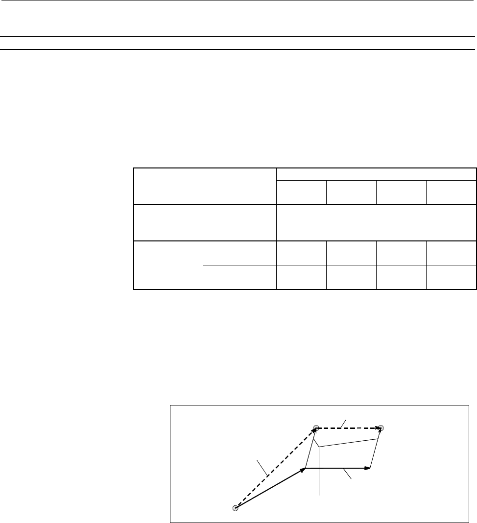
- Offset with tool movement
The tool path is offset by the X, Y, and Z tool offset values for the
programmed path. The tool offset distance corresponding to the
number specified by the T code is added to or subtracted from the end
position of each programmed block.
The vector with tool offset X, Y, and Z is called the offset vector.
Offset is the same as the offset vector.
This move command block
contains the offset command
with T code
Tool path after offset
Programmed path
Offset by tool offset X, Z (offset vector)
Offset operation with tool movement
Contents Summary of 30i/300i/300is-Model A, 31i/310i/310is-Model A and A5, 32i/320i/320is-Model A Users manual
- Page 1FANUC Series 30*/300*/300*s-MODEL A FANUC Series 31*/310*/310*s-MODEL A5 FANUC Series 31*/310*/310*s-MODEL A FANUC Series 32*/320*/320*s-MODEL A For Lathe System USER’S MANUAL B-63944EN-1/02
- Page 2• No part of this manual may be reproduced in any form. • All specifications and designs are subject to change without notice. The export of this product is subject to the authorization of the government of the country from where the product is exported. In this manual we have tried as much as possi
- Page 3B-63944EN-1/02 SAFETY PRECAUTIONS SAFETY PRECAUTIONS This section describes the safety precautions related to the use of CNC units. It is essential that these precautions be observed by users to ensure the safe operation of machines equipped with a CNC unit (all descriptions in this section assume t
- Page 4SAFETY PRECAUTIONS B-63944EN-2/02 1.1 DEFINITION OF WARNING, CAUTION, AND NOTE This manual includes safety precautions for protecting the user and preventing damage to the machine. Precautions are classified into Warning and Caution according to their bearing on safety. Also, supplementary informati
- Page 5B-63944EN-2/02 SAFETY PRECAUTIONS 1.2 GENERAL WARNINGS AND CAUTIONS WARNING 1 Never attempt to machine a workpiece without first checking the operation of the machine. Before starting a production run, ensure that the machine is operating correctly by performing a trial run using, for example, the s
- Page 6SAFETY PRECAUTIONS B-63944EN-2/02 WARNING 5 The parameters for the CNC and PMC are factory-set. Usually, there is not need to change them. When, however, there is not alternative other than to change a parameter, ensure that you fully understand the function of the parameter before making any change
- Page 7B-63944EN-2/02 SAFETY PRECAUTIONS NOTE Programs, parameters, and macro variables are stored in nonvolatile memory in the CNC unit. Usually, they are retained even if the power is turned off. Such data may be deleted inadvertently, however, or it may prove necessary to delete all data from nonvolatil
- Page 8SAFETY PRECAUTIONS B-63944EN-2/02 1.3 WARNINGS AND CAUTIONS RELATED TO PROGRAMMING This section covers the major safety precautions related to programming. Before attempting to perform programming, read the supplied User’s Manual carefully such that you are fully familiar with their contents. WARNIN
- Page 9B-63944EN-2/02 SAFETY PRECAUTIONS WARNING 5 Constant surface speed control When an axis subject to constant surface speed control approaches the origin of the workpiece coordinate system, the spindle speed may become excessively high. Therefore, it is necessary to specify a maximum allowable speed.
- Page 10SAFETY PRECAUTIONS B-63944EN-2/02 WARNING 11 Programmable mirror image Note that programmed operations vary considerably when a programmable mirror image is enabled. 12 Compensation function If a command based on the machine coordinate system or a reference position return command is issued in compe
- Page 11B-63944EN-2/02 SAFETY PRECAUTIONS 1.4 WARNINGS AND CAUTIONS RELATED TO HANDLING This section presents safety precautions related to the handling of machine tools. Before attempting to operate your machine, read the supplied User’s Manual carefully, such that you are fully familiar with their content
- Page 12SAFETY PRECAUTIONS B-63944EN-2/02 WARNING 5 Disabled override If override is disabled (according to the specification in a macro variable) during threading, rigid tapping, or other tapping, the speed cannot be predicted, possibly damaging the tool, the machine itself, the workpiece, or causing injur
- Page 13B-63944EN-2/02 SAFETY PRECAUTIONS WARNING 10 Manual intervention If manual intervention is performed during programmed operation of the machine, the tool path may vary when the machine is restarted. Before restarting the machine after manual intervention, therefore, confirm the settings of the manua
- Page 14SAFETY PRECAUTIONS B-63944EN-2/02 1.5 WARNINGS RELATED TO DAILY MAINTENANCE WARNING 1 Memory backup battery replacement When replacing the memory backup batteries, keep the power to the machine (CNC) turned on, and apply an emergency stop to the machine. Because this work is performed with the power
- Page 15B-63944EN-2/02 SAFETY PRECAUTIONS WARNING 2 Absolute pulse coder battery replacement When replacing the memory backup batteries, keep the power to the machine (CNC) turned on, and apply an emergency stop to the machine. Because this work is performed with the power on and the cabinet open, only thos
- Page 16SAFETY PRECAUTIONS B-63944EN-2/02 WARNING 3 Fuse replacement Before replacing a blown fuse, however, it is necessary to locate and remove the cause of the blown fuse. For this reason, only those personnel who have received approved safety and maintenance training may perform this work. When replacin
- Page 17B-63944EN-1/02 TABLE OF CONTENTS TABLE OF CONTENTS SAFETY PRECAUTIONS............................................................................s-1 I. GENERAL 1 GENERAL ............................................................................................... 3 1.1 NOTES ON READING THIS MANUAL
- Page 18TABLE OF CONTENTS B-63944EN-1/02 4.2.4 Finishing Cycle (G70) ............................................................................................73 4.2.5 End Face Peck Drilling Cycle (G74)......................................................................77 4.2.6 Outer Diameter / Internal
- Page 19B-63944EN-1/02 TABLE OF CONTENTS 5.3 OVERVIEW OF CUTTER COMPENSATION (G40-G42).......................... 164 5.4 DETAILS OF CUTTER OR TOOL NOSE RADIUS COMPENSATION...... 171 5.4.1 Overview ..............................................................................................................1
- Page 20TABLE OF CONTENTS B-63944EN-1/02 6.4.2 Stock Removal in Facing (G72) ...........................................................................288 6.4.3 Pattern Repeating (G73).......................................................................................294 6.4.4 Finishing Cycle (G70) ....
- Page 21B-63944EN-1/02 TABLE OF CONTENTS 2.1.3 Input of Tool Offset Value Measured B...............................................................364 2.1.4 Counter Input of Offset value...............................................................................367 2.1.5 Setting the Workpiece Coordinate
- Page 22
- Page 23I. GENERA
- Page 24
- Page 25B-63944EN-1/02 GENERAL 1.GENERAL 1 GENERAL This manual consists of the following parts: About this manual I. GENERAL Describes chapter organization, applicable models, related manuals, and notes for reading this manual. II. PROGRAMMING Describes each function: Format used to program functions in the
- Page 261.GENERAL GENERAL B-63944EN-1/02 Applicable models The models covered by this manual, and their abbreviations are : Model name Abbreviation FANUC Series 30i-MODEL A 30i –A Series 30i FANUC Series 300i-MODEL A 300i–A Series 300i FANUC Series 300is-MODEL A 300is–A Series 300is FANUC Series 31i-MODEL A
- Page 27B-63944EN-1/02 GENERAL 1.GENERAL Related manuals of Series 30i/300i/300is- MODEL A Series 31i/310i/310is- MODEL A Series 31i/310i/310is- MODEL A5 Series 32i/320i/320is- MODEL A The following table lists the manuals related to Series 30i/300i /300is- A, Series 31i/310i /310is-A, Series 31i/310i /310i
- Page 281.GENERAL GENERAL B-63944EN-1/02 Related manuals of SERVO MOTOR αis/αi/βis/βi series The following table lists the manuals related to SERVO MOTOR αis/αi/βis/βi series Table 2 Related manuals Specification Manual name number FANUC AC SERVO MOTOR αis series FANUC AC SERVO MOTOR αi series B-65262EN DES
- Page 29B-63944EN-1/02 GENERAL 1.GENERAL 1.1 NOTES ON READING THIS MANUAL CAUTION 1 The function of an CNC machine tool system depends not only on the CNC, but on the combination of the machine tool, its magnetic cabinet, the servo system, the CNC, the operator's panels, etc. It is too difficult to describe
- Page 30
- Page 31II. PROGRAMMIN
- Page 32
- Page 33B-63944EN-1/02 PROGRAMMING 1.GENERAL 1 GENERAL - 11 -
- Page 341.GENERAL PROGRAMMING B-63944EN-1/02 1.1 OFFSET Explanation - Tool offset Usually, several tools are used for machining one workpiece. The tools have different tool length. It is very troublesome to change the program in accordance with the tools. Therefore, the length of each tool used should be me
- Page 35B-63944EN-1/01 PROGRAMMING 2.PREPARATORY FUNCTION (G FUNCTION) 2 PREPARATORY FUNCTION (G FUNCTION) A number following address G determines the meaning of the command for the concerned block. G codes are divided into the following two types. Type Meaning The G code is effective only in the block in w
- Page 362.PREPARATORY FUNCTION (G FUNCTION) PROGRAMMING B-63944EN-1/01 Explanation 1. When the clear state (parameter CLR (No. 3402#6)) is set at power-up or reset, the modal G codes are placed in the states described below. (1) The modal G codes are placed in the states marked with as indicated in Table. (
- Page 37B-63944EN-1/01 PROGRAMMING 2.PREPARATORY FUNCTION (G FUNCTION) Table 2(a) G code list G code system Group Function A B C G00 G00 G00 Positioning (Rapid traverse) G01 G01 G01 Linear interpolation (Cutting feed) G02 G02 G02 Circular interpolation CW or helical interpolation CW G03 G03 G03 Circular int
- Page 382.PREPARATORY FUNCTION (G FUNCTION) PROGRAMMING B-63944EN-1/01 Table 2(a) G code list G code system Group Function A B C G27 G27 G27 Reference position return check G28 G28 G28 Return to reference position G29 G29 G29 Movement from reference position G30 G30 G30 00 2nd, 3rd and 4th reference positio
- Page 39B-63944EN-1/01 PROGRAMMING 2.PREPARATORY FUNCTION (G FUNCTION) Table 2(a) G code list G code system Group Function A B C G50 G92 G92 Coordinate system setting or max. spindle speed clamp 00 G50.3 G92.1 G92.1 Workpiece coordinate system preset - G50 G50 Scaling cancel 18 - G51 G51 Scaling G50.1 G50.1
- Page 402.PREPARATORY FUNCTION (G FUNCTION) PROGRAMMING B-63944EN-1/01 Table 2(a) G code list G code system Group Function A B C G80 G80 G80 10 Canned cycle cancel for drilling G80.5 G80.5 G80.5 27 Electronic gear box 2 pair: synchronization cancellation G80.8 G80.8 G80.8 28 Electronic gear box: synchroniza
- Page 41B-63944EN-1/02 PROGRAMMING 3.INTERPOLATION FUNCTION 3 INTERPOLATION FUNCTION - 19 -
- Page 423.INTERPOLATION FUNCTION PROGRAMMING B-63944EN-1/02 3.1 CONSTANT LEAD THREADING (G32) Tapered screws and scroll threads in addition to equal lead straight threads can be cut by using a G32 command. The spindle speed is read from the position coder on the spindle in real time and converted to a cutti
- Page 43B-63944EN-1/02 PROGRAMMING 3.INTERPOLATION FUNCTION X Tapered thread LX α Z LZ α≤45° lead is LZ α≥45° lead is LX Fig. 3.1 (c) LZ and LX of a tapered thread In general, the lag of the servo system, etc. will produce somewhat incorrect leads at the starting and ending points of a thread cut. To compen
- Page 443.INTERPOLATION FUNCTION PROGRAMMING B-63944EN-1/02 Example 1. Straight threading The following values are used in programming : Thread lead :4mm X axis δ1=3mm 30mm δ2=1.5mm Depth of cut :1mm (cut twice) δ1 (Metric input, diameter programming) δ2 G00 U-62.0 ; Z axis G32 W-74.5 F4.0 ; G00 U62.0 ; W74
- Page 45B-63944EN-1/02 PROGRAMMING 3.INTERPOLATION FUNCTION WARNING 1 Feedrate override is effective (fixed at 100%) during threading. 2 It is very dangerous to stop feeding the thread cutter without stopping the spindle. This will suddenly increase the cutting depth. Thus, the feed hold function is ineffec
- Page 463.INTERPOLATION FUNCTION PROGRAMMING B-63944EN-1/02 3.2 CONTINUOUS THREADING Threading blocks can be programmed successively to eliminate a discontinuity due to a discontinuous movement in machining by adjacent blocks. Explanation Since the system is controlled in such a manner that the synchronism
- Page 47B-63944EN-1/02 PROGRAMMING 3.INTERPOLATION FUNCTION 3.3 MULTIPLE THREADING Using the Q address to specify an angle between the one-spindle-rotation signal and the start of threading shifts the threading start angle, making it possible to produce multiple-thread screws with ease. L L : Lead Fig. 3.3
- Page 483.INTERPOLATION FUNCTION PROGRAMMING B-63944EN-1/02 - Specifiable start angle range A start angle (Q) of between 0 and 360000 (in 0.001-degree units) can be specified. If a value greater than 360000 (360 degrees) is specified, it is rounded down to 360000 (360 degrees). - Combined threading cycle (G
- Page 49B-63944EN-1/02 PROGRAMMING 3.INTERPOLATION FUNCTION 3.4 TORQUE LIMIT SKIP (G31 P99) With the motor torque limited (for example, by a torque limit command, issued through the PMC window), a move command following G31 P99 (or G31 P98) can cause the same type of cutting feed as with G01 (linear interpo
- Page 503.INTERPOLATION FUNCTION PROGRAMMING B-63944EN-1/02 Limitation - Axis command Only one axis can be controlled in each block with G31 P98/99. If two or more axes are specified to be controlled in such blocks, or no axis command is issued, alarm PS0369 is generated. - Simple synchronous control and an
- Page 51B-63944EN-1/02 PROGRAMMING 4.FUNCTIONS TO SIMPLIFY PROGRAMMING 4 FUNCTIONS TO SIMPLIFY PROGRAMMING This chapter explains the following items: 4.1 CANNED CYCLE (G90, G92, G94) 4.2 MULTIPLE REPETITIVE CYCLE (G70-G76) 4.3 CANNED CYCLE FOR DRILLING 4.4 RIGID TAPPING 4.5 CHAMFERING AND CORNER R 4.6 MIRRO
- Page 524.FUNCTIONS TO SIMPLIFY PROGRAMMING PROGRAMMING B-63944EN-1/02 4.1 CANNED CYCLE (G90, G92, G94) There are three canned cycles : the outer diameter/internal diameter cutting canned cycle (G90), the threading canned cycle (G92), and the end face turning canned cycle (G94). NOTE 1 Explanatory figures i
- Page 53B-63944EN-1/02 PROGRAMMING 4.FUNCTIONS TO SIMPLIFY PROGRAMMING 4.1.1 Outer Diameter/Internal Diameter Cutting Cycle (G90) This cycle performs straight or taper cutting in the direction of the length. 4.1.1.1 Straight cutting cycle Format G90X(U)_Z(W)_F_; X_,Z_ : Coordinates of the cutting end point
- Page 544.FUNCTIONS TO SIMPLIFY PROGRAMMING PROGRAMMING B-63944EN-1/02 NOTE In single block mode, operations 1, 2, 3 and 4 are performed by pressing the cycle start button once. - Canceling the mode To cancel the canned cycle mode, specify a group 01 G code other than G90, G92, or G94. - 32 -
- Page 55B-63944EN-1/02 PROGRAMMING 4.FUNCTIONS TO SIMPLIFY PROGRAMMING 4.1.1.2 Taper cutting cycle Format G90 X(U)_Z(W)_R_F_; X_,Z_ : Coordinates of the cutting end point (point A' in the figure below) in the direction of the length U_,W_ : Travel distance to the cutting end point (point A' in the figure be
- Page 564.FUNCTIONS TO SIMPLIFY PROGRAMMING PROGRAMMING B-63944EN-1/02 NOTE In single block mode, operations 1, 2, 3, and 4 are performed by pressing the cycle start button once. - Relationship between the sign of the taper amount and tool path The tool path is determined according to the relationship betwe
- Page 57B-63944EN-1/02 PROGRAMMING 4.FUNCTIONS TO SIMPLIFY PROGRAMMING 4.1.2 Threading Cycle (G92) 4.1.2.1 Straight threading cycle Format G92 X(U)_Z(W)_F_Q_; X_,Z_ : Coordinates of the cutting end point (point A' in the figure below) in the direction of the length U_,W_ : Travel distance to the cutting end
- Page 584.FUNCTIONS TO SIMPLIFY PROGRAMMING PROGRAMMING B-63944EN-1/02 (3) Operation 3 moves the tool to the start coordinate of the second axis on the plane (start X-coordinate for the ZX plane) in rapid traverse. (Retraction after chamfering) (4) Operation 4 moves the tool to the start coordinate of the f
- Page 59B-63944EN-1/02 PROGRAMMING 4.FUNCTIONS TO SIMPLIFY PROGRAMMING - Retraction after chamfering The following table lists the feedrate, type of acceleration/deceleration after interpolation, and time constant of retraction after chamfering. Parameter Parameter CFR Description No. 1466 (No. 1611#0) 0 Ot
- Page 604.FUNCTIONS TO SIMPLIFY PROGRAMMING PROGRAMMING B-63944EN-1/02 - Threading cycle retract When the "threading cycle retract" option function is used, feed hold may be applied during threading (operation 2). In this case, the tool immediately retracts with chamfering and returns to the start point on
- Page 61B-63944EN-1/02 PROGRAMMING 4.FUNCTIONS TO SIMPLIFY PROGRAMMING 4.1.2.2 Taper threading cycle Format G92 X(U)_Z(W)_R_F_Q_; X_,Z_ : Coordinates of the cutting end point (point A' in the figure below) in the direction of the length U_,W_ : Travel distance to the cutting end point (point A' in the figur
- Page 624.FUNCTIONS TO SIMPLIFY PROGRAMMING PROGRAMMING B-63944EN-1/02 Explanation The ranges of thread leads and restrictions related to the spindle speed are the same as for threading with G32. The figure of a taper is determined by the coordinates of the cutting end point (A') in the direction of the len
- Page 63B-63944EN-1/02 PROGRAMMING 4.FUNCTIONS TO SIMPLIFY PROGRAMMING - Relationship between the sign of the taper amount and tool path The tool path is determined according to the relationship between the sign of the taper amount (address R) and the cutting end point in the direction of the length in the
- Page 644.FUNCTIONS TO SIMPLIFY PROGRAMMING PROGRAMMING B-63944EN-1/02 4.1.3 End Face Turning Cycle (G94) 4.1.3.1 Face cutting cycle Format G92 X(U)_Z(W)_F_; X_,Z_ : Coordinates of the cutting end point (point A' in the figure below) in the direction of the end face U_,W_ : Travel distance to the cutting en
- Page 65B-63944EN-1/02 PROGRAMMING 4.FUNCTIONS TO SIMPLIFY PROGRAMMING - Canceling the mode To cancel the canned cycle mode, specify a group 01 G code other than G90, G92, or G94. 4.1.3.2 Taper cutting cycle Format G94 X(U)_Z(W)_R_F_; X_,Z_ : Coordinates of the cutting end point (point A' in the figure belo
- Page 664.FUNCTIONS TO SIMPLIFY PROGRAMMING PROGRAMMING B-63944EN-1/02 - Operations A taper cutting cycle performs the same four operations as a face cutting cycle. However, operation 1 moves the tool from the start point (A) to the position obtained by adding the taper amount to the specified coordinate of
- Page 67B-63944EN-1/02 PROGRAMMING 4.FUNCTIONS TO SIMPLIFY PROGRAMMING 4.1.4 How to Use Canned Cycles (G90, G92, G94) An appropriate canned cycle is selected according to the shape of the material and the shape of the product. - Straight cutting cycle (G90) Shape of material Shape of product - Taper cutting
- Page 684.FUNCTIONS TO SIMPLIFY PROGRAMMING PROGRAMMING B-63944EN-1/02 - Face cutting cycle (G94) Shape of material Shape of product - Face taper cutting cycle (G94) Shape of material Shape of product - 46 -
- Page 69B-63944EN-1/02 PROGRAMMING 4.FUNCTIONS TO SIMPLIFY PROGRAMMING 4.1.5 Canned Cycle and Tool Nose Radius Compensation When tool nose radius compensation is applied, the tool nose center path and offset direction are as shown below. At the start point of a cycle, the offset vector is canceled. Offset s
- Page 704.FUNCTIONS TO SIMPLIFY PROGRAMMING PROGRAMMING B-63944EN-1/02 Threading cycle (G92) Tool nose radius compensation cannot be applied. Differences between this CNC and the FANUC Series 16i/18i/21i NOTE This CNC is the same as the FANUC Series 16i/18i/21i in the offset direction, but differs from the
- Page 71B-63944EN-1/02 PROGRAMMING 4.FUNCTIONS TO SIMPLIFY PROGRAMMING 4.1.6 Restrictions on Canned Cycles Limitation - Modal Since data items X (U), Z (W), and R in a canned cycle are modal values common to G90, G92, and G94. For this reason, if a new X (U), Z (W), or R value is not specified, the previous
- Page 724.FUNCTIONS TO SIMPLIFY PROGRAMMING PROGRAMMING B-63944EN-1/02 - Block in which no move command is specified In a block in which no move command is specified in the canned cycle mode, a canned cycle is also performed. For example, a block containing only EOB or a block in which none of the M, S, and
- Page 73B-63944EN-1/02 PROGRAMMING 4.FUNCTIONS TO SIMPLIFY PROGRAMMING 4.2 MULTIPLE REPETITIVE CYCLE (G70-G76) The multiple repetitive cycle is canned cycles to make CNC programming easy. For instance, the data of the finish work shape describes the tool path for rough machining. And also, a canned cycles f
- Page 744.FUNCTIONS TO SIMPLIFY PROGRAMMING PROGRAMMING B-63944EN-1/02 4.2.1 Stock Removal in Turning (G71) There are two types of stock removals in turning : Type I and II. To use type II, the "multiple repetitive canned cycle 2" option function is required. Format ZpXp plane G71 U(∆d) R(e) ; G71 P(ns) Q(n
- Page 75B-63944EN-1/02 PROGRAMMING 4.FUNCTIONS TO SIMPLIFY PROGRAMMING Diameter/radius Unit Sign programming Depends on the increment Not ∆d system for the reference Radius programming required axis. Depends on the increment Not e system for the reference Radius programming required axis. Depends on Depends
- Page 764.FUNCTIONS TO SIMPLIFY PROGRAMMING PROGRAMMING B-63944EN-1/02 NOTE 1 While both ∆d and ∆u are specified by the same address, the meanings of them are determined by the presence of addresses P and Q. 2 The cycle machining is performed by G71 command with P and Q specification. 3 F, S, and T function
- Page 77B-63944EN-1/02 PROGRAMMING 4.FUNCTIONS TO SIMPLIFY PROGRAMMING Limitation (1) For U(+), a figure for which a position higher than the cycle start point is specified cannot be machined. For U(-), a figure for which a position lower than the cycle start point is specified cannot be machined. (2) For t
- Page 784.FUNCTIONS TO SIMPLIFY PROGRAMMING PROGRAMMING B-63944EN-1/02 - Types I and II Selection of type I or II For G71, there are types I and II. When the target figure has pockets, be sure to use type II. Escaping operation after rough cutting in the direction of the first axis on the plane (Z-axis for
- Page 79B-63944EN-1/02 PROGRAMMING 4.FUNCTIONS TO SIMPLIFY PROGRAMMING (2) The figure along path A'-B must show monotone increase or decrease in the directions of both axes forming the plane (Z- and X-axes for the ZX plane). It must not have any pocket as shown in the figure below. A A’ X Z No pockets are a
- Page 804.FUNCTIONS TO SIMPLIFY PROGRAMMING PROGRAMMING B-63944EN-1/02 - Type II (R) (F) C (R) A B ∆d (R) (F) ∆d (F) Target figure ∆u/2 A’ +X (F): Cutting feed ∆W +Z (R): Rapid traverse Fig. 4.2.1 (e) Cutting path in stock removal in turning (type II) When a target figure passing through A, A', and B in thi
- Page 81B-63944EN-1/02 PROGRAMMING 4.FUNCTIONS TO SIMPLIFY PROGRAMMING (2) The figure need not show monotone increase or decrease in the direction of the second axis on the plane (X-axis for the ZX plane) and it may have concaves (pockets). +X +Z 10 ... 3 2 1 Fig. 4.2.1 (f) Figure having pockets (type II) T
- Page 824.FUNCTIONS TO SIMPLIFY PROGRAMMING PROGRAMMING B-63944EN-1/02 +X +Z Fig. 4.2.1 (h) Figure which can be machined (type II) (3) After turning, the tool cuts the workpiece along its figure and escapes in cutting feed. Escaping amount e (specified in the command or parameter No. 5133) Escaping after cu
- Page 83B-63944EN-1/02 PROGRAMMING 4.FUNCTIONS TO SIMPLIFY PROGRAMMING (5) After all rough cutting terminates along the first axis on the plane (Z-axis for the ZX plane), the tool temporarily returns to the cycle start point. At this time, when there is a position whose height equals to that at the start po
- Page 844.FUNCTIONS TO SIMPLIFY PROGRAMMING PROGRAMMING B-63944EN-1/02 (b) When the figure shows monotone increase along the first axis on the plane (Z-axis for the ZX plane) Rough cutting is performed in the order <1>, <2>, and <3> from the leftmost pocket. <1> <2> <3> +X +Z Fig. 4.2.1 (m) Rough cutting or
- Page 85B-63944EN-1/02 PROGRAMMING 4.FUNCTIONS TO SIMPLIFY PROGRAMMING Cuts the workpiece at the cutting feedrate and escapes to the direction of 45 degrees. (Operation 19) Then, moves to the height of point D in rapid traverse. (Operation 20) Then, moves to the position the amount of g before point D. (Ope
- Page 864.FUNCTIONS TO SIMPLIFY PROGRAMMING PROGRAMMING B-63944EN-1/02 This cycle operation is performed according to the figure determined by the tool nose radius compensation path when the offset vector is 0 at start point A and start-up is performed in a block between path A-A'. B A Position between A- A
- Page 87B-63944EN-1/02 PROGRAMMING 4.FUNCTIONS TO SIMPLIFY PROGRAMMING 4.2.2 Stock Removal in Facing (G72) This cycle is the same as G71 except that cutting is performed by an operation parallel to the second axis on the plane (X-axis for the ZX plane). Format ZpXp plane G72 W(∆d) R(e) ; G72 P(ns) Q(nf) U(∆
- Page 884.FUNCTIONS TO SIMPLIFY PROGRAMMING PROGRAMMING B-63944EN-1/02 Diameter/radius Unit Sign programming Depends on the increment Not ∆d system for the reference Radius programming required axis. Depends on the increment Not e system for the reference Radius programming required axis. Depends on Depends
- Page 89B-63944EN-1/02 PROGRAMMING 4.FUNCTIONS TO SIMPLIFY PROGRAMMING Explanation - Operations When a target figure passing through A, A', and B in this order is given by a program, the specified area is removed by ∆d (depth of cut), with the finishing allowance specified by ∆u/2 and ∆w left. NOTE 1 While
- Page 904.FUNCTIONS TO SIMPLIFY PROGRAMMING PROGRAMMING B-63944EN-1/02 Limitation (1) For W(+), a figure for which a position higher than the cycle start point is specified cannot be machined. For W(-), a figure for which a position lower than the cycle start point is specified cannot be machined. (2) For t
- Page 91B-63944EN-1/02 PROGRAMMING 4.FUNCTIONS TO SIMPLIFY PROGRAMMING Selecting type I or II In the start block for the target figure (sequence number ns), select type I or II. (1) When type I is selected Specify the first axis on the plane (Z-axis for the ZX plane). Do not specify the second axis on the p
- Page 924.FUNCTIONS TO SIMPLIFY PROGRAMMING PROGRAMMING B-63944EN-1/02 4.2.3 Pattern Repeating (G73) This function permits cutting a fixed pattern repeatedly, with a pattern being displaced bit by bit. By this cutting cycle, it is possible to efficiently cut work whose rough shape has already been made by a
- Page 93B-63944EN-1/02 PROGRAMMING 4.FUNCTIONS TO SIMPLIFY PROGRAMMING ∆u : Distance of the finishing allowance in the direction of the second axis on the plane (X-axis for the ZX plane) ∆w : Distance of the finishing allowance in the direction of the first axis on the plane (Z-axis for the ZX plane) f, s,
- Page 944.FUNCTIONS TO SIMPLIFY PROGRAMMING PROGRAMMING B-63944EN-1/02 Explanation - Operations When a target figure passing through A, A', and B in this order is given by a program, rough cutting is performed the specified number of times, with the finishing allowance specified by ∆u/2 and ∆w left. NOTE 1
- Page 95B-63944EN-1/02 PROGRAMMING 4.FUNCTIONS TO SIMPLIFY PROGRAMMING 4.2.4 Finishing Cycle (G70) After rough cutting by G71, G72 or G73, the following command permits finishing. Format G70 P(ns) Q(nf) ; ns : Sequence number of the first block for the program of finishing shape. nf : Sequence number of the
- Page 964.FUNCTIONS TO SIMPLIFY PROGRAMMING PROGRAMMING B-63944EN-1/02 Example G71 P100 Q200 ...; N100 ...; ...; ...; N200 ...; G71 P300 Q400 ...; N300 ...; ...; ...; N400 ...; ...; ...; G70 P100 Q200 ; (Executed without a search for the first to third cycles) G70 P300 Q400 ; (Executed after a search for th
- Page 97B-63944EN-1/02 PROGRAMMING 4.FUNCTIONS TO SIMPLIFY PROGRAMMING Example Stock removal in facing (G72) X axis 2 Start point 7 2 88 110 φ160 φ120 φ80 φ40 Z axis 60 10 10 10 20 20 2 190 (Diameter designation for X axis, metric input) N010 G50 X220.0 Z190.0 ; N011 G00 X176.0 Z132.0 ; N012 G72 W7.0 R1.0 ;
- Page 984.FUNCTIONS TO SIMPLIFY PROGRAMMING PROGRAMMING B-63944EN-1/02 Pattern repeating (G73) 16 B 16 X axis 110 130 14 2 φ180 φ160 φ120 φ80 Z axis 0 2 14 20 40 10 40 10 20 40 220 (Diameter designation, metric input) N010 G50 X260.0 Z220.0 ; N011 G00 X220.0 Z160.0 ; N012 G73 U14.0 W14.0 R3 ; N013 G73 P014
- Page 99B-63944EN-1/02 PROGRAMMING 4.FUNCTIONS TO SIMPLIFY PROGRAMMING 4.2.5 End Face Peck Drilling Cycle (G74) This cycle enables chip breaking in outer diameter cutting. If the second axis on the plane (X-axis (U-axis) for the ZX plane) and address P are omitted, operation is performed only along the firs
- Page 1004.FUNCTIONS TO SIMPLIFY PROGRAMMING PROGRAMMING B-63944EN-1/02 ∆k' ∆k ∆k ∆k ∆k [0 < ∆k’ ≤ ∆k] ∆d A ∆i C (R) (R) (F) (F) (F) (F) (F) U/2 (R) (R) (R) (R) ∆i [0 < ∆i’ ≤ ∆i] ∆i’ X Z W B +X (R) ... Rapid traverse e (F) ... Cutting feed +Z Fig. 4.2.5 (a) Cutting path in end face peek drilling cycle Explan
- Page 101B-63944EN-1/02 PROGRAMMING 4.FUNCTIONS TO SIMPLIFY PROGRAMMING 4.2.6 Outer Diameter / Internal Diameter Drilling Cycle (G75) This cycle is equivalent to G74 except that the second axis on the plane (X-axis for the ZX plane) changes places with the first axis on the plane (Z-axis for the ZX plane). T
- Page 1024.FUNCTIONS TO SIMPLIFY PROGRAMMING PROGRAMMING B-63944EN-1/02 C (R) A (R) (F) ∆i (R) e (F) ∆i (R) U/2 (F) ∆i (R) (F) ∆i (R) (F) ∆i’ B ∆d ∆k X Z W +X (R) ... Rapid traverse (F) ... Cutting feed +Z Fig. 4.2.6 (b) Outer diameter/internal diameter drilling cycle Explanation - Operations A cycle operati
- Page 103B-63944EN-1/02 PROGRAMMING 4.FUNCTIONS TO SIMPLIFY PROGRAMMING 4.2.7 Multiple Threading Cycle (G76) This threading cycle performs one edge cutting by the constant amount of cut. Format G76 P(m) (r) (a) Q(∆dmin) R(d ) ; G76 X(U)_ Z(W)_ R(i ) P(k ) Q(∆d) F (L ) ; m : Repetitive count in finishing (1 t
- Page 1044.FUNCTIONS TO SIMPLIFY PROGRAMMING PROGRAMMING B-63944EN-1/02 Diameter/radius Unit Sign programming Depends on the increment Not ∆dmin Radius programming system for the reference axis. required Depends on the increment Not d Radius programming system for the reference axis. required Depends on the
- Page 105B-63944EN-1/02 PROGRAMMING 4.FUNCTIONS TO SIMPLIFY PROGRAMMING - Repetitive count in finishing The last finishing cycle (cycle in which the finishing allowance is removed by cutting) is repeated. +X k +Z Last finishing cycle d (finishing allowance) Explanation - Operations This cycle performs thread
- Page 1064.FUNCTIONS TO SIMPLIFY PROGRAMMING PROGRAMMING B-63944EN-1/02 - Relationship between the sign of the taper amount and tool path The signs of incremental dimensions for the cycle shown in Fig. 4.2.7 (c) are as follows: Cutting end point in the direction of the length for U and W: Minus (determined a
- Page 107B-63944EN-1/02 PROGRAMMING 4.FUNCTIONS TO SIMPLIFY PROGRAMMING - Thread chamfering Thread chamfering can be performed in this threading cycle. A signal from the machine tool initiates thread chamfering. The maximum amount of thread chamfering (r) that can be specified in the command is 99 (9.9L). Th
- Page 1084.FUNCTIONS TO SIMPLIFY PROGRAMMING PROGRAMMING B-63944EN-1/02 - Shifting the start angle The threading start angle cannot be shifted. - Feed hold in a threading cycle When the threading cycle retract function is not used, the machine stops at the end point of retraction after chamfering (point E on
- Page 109B-63944EN-1/02 PROGRAMMING 4.FUNCTIONS TO SIMPLIFY PROGRAMMING Example 1.8 3.68 X axis 1.8 ϕ60.64 ϕ68 Z axis 0 6 25 105 G80 X80.0 Z130.0; G76 P011060 Q100 R200 ; G76 X60.64 Z25.0 P3680 Q1800 F6.0 ; - 87 -
- Page 1104.FUNCTIONS TO SIMPLIFY PROGRAMMING PROGRAMMING B-63944EN-1/02 4.2.8 Restrictions on Multiple Repetitive Cycle (G70-G76) Programmed commands - Program memory Programs using G70, G71, G72, or G73 must be stored in the program memory. The use of the mode in which programs stored in the program memory
- Page 111B-63944EN-1/02 PROGRAMMING 4.FUNCTIONS TO SIMPLIFY PROGRAMMING Relation with other functions - Manual intervention While a multiple repetitive cycle (G70 to G76) is being executed, it is possible to stop the cycle and to perform manual intervention. The setting of manual absolute on or off is effect
- Page 1124.FUNCTIONS TO SIMPLIFY PROGRAMMING PROGRAMMING B-63944EN-1/02 4.3 CANNED CYCLE FOR DRILLING Canned cycles for drilling make it easier for the programmer to create programs. With a canned cycle, a frequently-used machining operation can be specified in a single block with a G function; without canne
- Page 113B-63944EN-1/02 PROGRAMMING 4.FUNCTIONS TO SIMPLIFY PROGRAMMING Operation 1 Initial level Operation 2 Operation 6 Point R level Operation 5 Operation 3 Rapid traverse Operation 4 Feed Fig. 4.3 (e) Operation sequence of canned cycle for drilling - Positioning axis and drilling axis The C-axis and X- o
- Page 1144.FUNCTIONS TO SIMPLIFY PROGRAMMING PROGRAMMING B-63944EN-1/02 - Return point level In G code system A, the tool returns to the initial level from the bottom of a hole. In G code system B or C, specifying G98 returns the tool to the initial level from the bottom of a hole and specifying G99 returns
- Page 115B-63944EN-1/02 PROGRAMMING 4.FUNCTIONS TO SIMPLIFY PROGRAMMING - M code used for C-axis clamp/unclamp When an M code specified in parameter No. 5110 for C-axis clamp/unclamp is coded in a program, the following operations occur. • The CNC issues the M code for C-axis clamp after the tool is position
- Page 1164.FUNCTIONS TO SIMPLIFY PROGRAMMING PROGRAMMING B-63944EN-1/02 4.3.1 Front Drilling Cycle (G83)/Side Drilling Cycle (G87) The peck drilling cycle or high-speed peck drilling cycle is used depending on the setting in RTR, bit 2 of parameter No. 5101. If depth of cut for each drilling is not specified
- Page 117B-63944EN-1/02 PROGRAMMING 4.FUNCTIONS TO SIMPLIFY PROGRAMMING - Peck drilling cycle (G83, G87) (parameter No. 5101#2 =1) Format G83 X(U)_ C(H)_ Z(W)_ R_ P_ Q_ F_ K_ M_ ; or G87 Z(W)_ C(H)_ X(U)_ R_ P_ Q_ F_ K_ M_ ; X_ C_ or Z_ C_ : Hole position data Z_ or X_ : The distance from point R to the bott
- Page 1184.FUNCTIONS TO SIMPLIFY PROGRAMMING PROGRAMMING B-63944EN-1/02 - Drilling cycle (G83 or G87) If depth of cut (Q) is not specified for each drilling, the normal drilling cycle is used. The tool is then retracted from the bottom of the hole in rapid traverse. Format G83 X(U)_ C(H)_ Z(W)_ R_ P_ F_ K_ M
- Page 119B-63944EN-1/02 PROGRAMMING 4.FUNCTIONS TO SIMPLIFY PROGRAMMING 4.3.2 Front Tapping Cycle (G84) / Side Tapping Cycle (G88) This cycle performs tapping. In this tapping cycle, when the bottom of the hole has been reached, the spindle is rotated in the reverse direction. Format G84 X(U)_ C(H)_ Z(W)_ R_
- Page 1204.FUNCTIONS TO SIMPLIFY PROGRAMMING PROGRAMMING B-63944EN-1/02 Example M51 ; Setting C-axis index mode ON M3 S2000 ; Rotating the drill G00 X50.0 C0.0 ; Positioning the drill along the X- and C- axes G84 Z-40.0 R-5.0 P500 F5.0 M31 ; Drilling hole 1 C90.0 M31 ; Drilling hole 2 C180.0 M31 ; Drilling h
- Page 121B-63944EN-1/02 PROGRAMMING 4.FUNCTIONS TO SIMPLIFY PROGRAMMING 4.3.3 Front Boring Cycle (G85) / Side Boring Cycle (G89) This cycle is used to bore a hole. Format G85 X(U)_ C(H)_ Z(W)_ R_ P_ F_ K_ M_ ; or G89 Z(W)_ C(H)_ X(U)_ R_ P_ F_ K_ M_ ; X_ C_ or Z_ C_ : Hole position data Z_ or X_ : The distan
- Page 1224.FUNCTIONS TO SIMPLIFY PROGRAMMING PROGRAMMING B-63944EN-1/02 4.3.4 Canned Cycle for Drilling Cancel (G80) G80 cancels canned cycle for drilling. Format G80 ; Explanation Canned cycle for drilling is canceled to perform normal operation. Point R and point Z are cleared. Other drilling data is also
- Page 123B-63944EN-1/02 PROGRAMMING 4.FUNCTIONS TO SIMPLIFY PROGRAMMING 4.3.5 Precautions to Be Taken by Operator - Reset and emergency stop Even when the controller is stopped by resetting or emergency stop in the course of drilling cycle, the drilling mode and drilling data are saved ; with this mind, ther
- Page 1244.FUNCTIONS TO SIMPLIFY PROGRAMMING PROGRAMMING B-63944EN-1/02 4.4 RIGID TAPPING Front face tapping cycles (G84) and side face tapping cycles (G88) can be performed either in conventional mode or rigid mode. In conventional mode, the spindle is rotated or stopped, in synchronization with the motion
- Page 125B-63944EN-1/02 PROGRAMMING 4.FUNCTIONS TO SIMPLIFY PROGRAMMING 4.4.1 FRONT FACE RIGID TAPPING CYCLE (G84) / SIDE FACE RIGID TAPPING CYCLE (G88) Controlling the spindle motor in the same way as a servo motor in rigid mode enables high-speed tapping. Format G84 X (U)_ C (H)_ Z (W)_ R_ P_ F_ K_ M_ ; or
- Page 1264.FUNCTIONS TO SIMPLIFY PROGRAMMING PROGRAMMING B-63944EN-1/02 In side face rigid tapping (G88), the plane first axis is used as the drilling axis and the other axes are used as positioning axes. Plane selection Drilling axis G17 Xp-Yp plane Yp G18 Zp-Xp plane Xp G19 Yp-Zp plane Zp Xp: X axis or its
- Page 127B-63944EN-1/02 PROGRAMMING 4.FUNCTIONS TO SIMPLIFY PROGRAMMING A G code cannot discriminate between front face tapping cycle and side face tapping cycle using Series 15 format commands. The drilling axis is determined by plane selection (G17/G18/G19). Specify the plane selection that becomes equival
- Page 1284.FUNCTIONS TO SIMPLIFY PROGRAMMING PROGRAMMING B-63944EN-1/02 - Override Various types of override functions are invalid. The following override functions can be enabled by setting corresponding parameters: • Extraction override • Override signal - Dry run Dry run can be executed also in G84 (G88).
- Page 129B-63944EN-1/02 PROGRAMMING 4.FUNCTIONS TO SIMPLIFY PROGRAMMING - C-axis clamp, C-axis unclamp It is possible to specify an M code for mechanically fixing or releasing the C-axis during rigid tapping. Adding an M code for clamp to the G84 (G88) block outputs both M codes. Descriptions of timing are p
- Page 1304.FUNCTIONS TO SIMPLIFY PROGRAMMING PROGRAMMING B-63944EN-1/02 - P Specify P in a block that performs drilling. If P is specified in a non-drilling block, it is not stored as modal data. - Cancel Do not specify a G code of the 01 group (G00 to G03 or G60 (when the parameter MDL (No. 5431#0) is set t
- Page 131B-63944EN-1/02 PROGRAMMING 4.FUNCTIONS TO SIMPLIFY PROGRAMMING 4.4.2 Peck Rigid Tapping Cycle (G84 or G88) Tapping a deep hole in rigid tapping mode may be difficult due to chips sticking to the tool or increased cutting resistance. In such cases, the peck rigid tapping cycle is useful. In this cycl
- Page 1324.FUNCTIONS TO SIMPLIFY PROGRAMMING PROGRAMMING B-63944EN-1/02 When rigid tapping is specified with G84 (G88) if PCP (bit 5 of parameter No. 5200) = 1, peck rigid tapping is assumed. G84 X(U)_ C(H)_Z(W)_ R_ P_ Q_ F_ K_ M_ ; or G88 Z(W)_ C(H)_X(U)_ R_ P_ Q_ F_ K_ M_ ; X_ C_ or Z_ C_ : Hole position d
- Page 133B-63944EN-1/02 PROGRAMMING 4.FUNCTIONS TO SIMPLIFY PROGRAMMING Explanation - Cutting start distance Cutting start distance d is set by parameter No. 5213. - Amount of return Amount of return for each time d is set by parameter No. 5213. - Return speed For the speed of return operation, a maximum of
- Page 1344.FUNCTIONS TO SIMPLIFY PROGRAMMING PROGRAMMING B-63944EN-1/02 - Interlock Interlock can also be applied in G84 (G88). - Feed hold and single block When parameter FHD (No. 5200#6) is set to 0, feed hold and single block are invalid in the G84 (G88) mode. When this bit is set to 1, they are valid. -
- Page 135B-63944EN-1/02 PROGRAMMING 4.FUNCTIONS TO SIMPLIFY PROGRAMMING - F command Specifying a value larger than the upper limit for cutting feed will cause alarm PS0011 to be issued. - Unit of F command Metric input Inch input Remarks Decimal point programming G98 1mm/min 0.01inch/min allowed Decimal poin
- Page 1364.FUNCTIONS TO SIMPLIFY PROGRAMMING PROGRAMMING B-63944EN-1/02 4.4.3 Canned Cycle Cancel (G80) The rigid tapping canned cycle is canceled. For how to cancel this cycle, see II-4.3.4. NOTE When the rigid tapping canned cycle is cancelled, the S value used for rigid tapping is also cleared (as if S0 i
- Page 137B-63944EN-1/02 PROGRAMMING 4.FUNCTIONS TO SIMPLIFY PROGRAMMING 4.4.4 Override during Rigid Tapping Various types of override functions are invalid. The following override functions can be enabled by setting corresponding parameters: • Extraction override • Override signal 4.4.4.1 Extraction override
- Page 1384.FUNCTIONS TO SIMPLIFY PROGRAMMING PROGRAMMING B-63944EN-1/02 The override to be applied is determined according to the setting of parameters and that in the command as shown in the table below. Parameter setting DOV = 1 DOV = 0 Command OV3 = 1 OV3 = 0 Within the range between Command in Spindle sp
- Page 139B-63944EN-1/02 PROGRAMMING 4.FUNCTIONS TO SIMPLIFY PROGRAMMING 4.4.4.2 Override signal By setting bit 4 (OVS) of parameter No. 5203 to 1, override can be applied to cutting/extraction operation during rigid tapping as follows: • Applying override using the feedrate override signal (When the second f
- Page 1404.FUNCTIONS TO SIMPLIFY PROGRAMMING PROGRAMMING B-63944EN-1/02 4.5 CHAMFERING AND CORNER R Overview A chamfering or corner R block can automatically be inserted between linear interpolation (G01) along a single axis and that along a single axis normal to that single axis. Chamfering or corner R is i
- Page 141B-63944EN-1/02 PROGRAMMING 4.FUNCTIONS TO SIMPLIFY PROGRAMMING - Chamfering Second axis on the selected plane → first axis on the selected plane (G17 plane: YP → XP, G18 plane: XP → ZP, G19 plane: ZP → YP) Format G17 plane: G01 YP(V)_ I(C)±i ; G18 plane: G01 XP(U)_ K(C)±k ; G19 plane: G01 ZP(W)_ J(C
- Page 1424.FUNCTIONS TO SIMPLIFY PROGRAMMING PROGRAMMING B-63944EN-1/02 - Corner R First axis on the selected plane → second axis on the selected plane (G17 plane: XP → YP, G18 plane: ZP → XP, G19 plane: YP → ZP) Format G17 plane: G01 XP(U)_ R±r ; G18 plane: G01 ZP(W)_ R±r ; G19 plane: G01 YP(V)_ R±r ; Expla
- Page 143B-63944EN-1/02 PROGRAMMING 4.FUNCTIONS TO SIMPLIFY PROGRAMMING - Corner R Second axis on the selected plane → first axis on the selected plane (G17 plane: YP → XP, G18 plane: XP → ZP, G19 plane: ZP → YP) Format G17 plane: G01 YP(V)_ R±r ; G18 plane: G01 XP(U)_ R±r ; G19 plane: G01 ZP(W)_ R±r ; Expla
- Page 1444.FUNCTIONS TO SIMPLIFY PROGRAMMING PROGRAMMING B-63944EN-1/02 Explanation By G01 specified for chamfering or corner R, the tool must be moved only along one of the two axes on the selected plane. The command in the next block must move the tool only along the other axis on the selected plane. Examp
- Page 145B-63944EN-1/02 PROGRAMMING 4.FUNCTIONS TO SIMPLIFY PROGRAMMING Limitation - Alarms In the following cases, an alarm is issued: 1) Chamfering or corner R is specified in a block for threading (alarm PS0050). 2) G01 is not specified in the block next to the G01 block in which chamfering or corner R is
- Page 1464.FUNCTIONS TO SIMPLIFY PROGRAMMING PROGRAMMING B-63944EN-1/02 9) An invalid sign is specified at I, J, K, R, or C (chamfering or corner R in the direction opposite to the movement in the next block is specified) (alarm PS0051). (See the figure below.) Chamfering block to G18 be inserted (positive X
- Page 147B-63944EN-1/02 PROGRAMMING 4.FUNCTIONS TO SIMPLIFY PROGRAMMING (1) When the chamfering and corner R function is not used In the G01 block in the cutter or tool nose radius compensation mode, the cutter or tool nose radius compensation direction can be specified at address I, J, or K. No chamfering i
- Page 1484.FUNCTIONS TO SIMPLIFY PROGRAMMING PROGRAMMING B-63944EN-1/02 4.6 MIRROR IMAGE FOR DOUBLE TURRET (G68, G69) Overview When a unit has a double turret consisting of two tool posts which face each other on the same controlled axis, mirror image can be applied to the X-axis with a G code command. Symme
- Page 149B-63944EN-1/02 PROGRAMMING 4.FUNCTIONS TO SIMPLIFY PROGRAMMING X40.0 Z180.0 T0101 ; Position tool post A at <1> G68 ; Shift the coordinate system by the distance A to B (120mm), and turn mirror image on. X80.0 Z120.0 T0202 ; Position tool post B at <2> G69 ; Shift the coordinate system by the distan
- Page 1504.FUNCTIONS TO SIMPLIFY PROGRAMMING PROGRAMMING B-63944EN-1/02 4.7 DIRECT DRAWING DIMENSION PROGRAMMING Overview Angles of straight lines, chamfering value, corner R values, and other dimensional values on machining drawings can be programmed by directly inputting these values. In addition, the cham
- Page 151B-63944EN-1/02 PROGRAMMING 4.FUNCTIONS TO SIMPLIFY PROGRAMMING Commands Movement of tool X (X3 , Z3) X2_ Z2_, C1_ ; A2 X3_ Z3_ ; 4 or ,A1_, C1_ ; C1 A1 X3_ Z3_, A2_ ; (X2 , Z2) (X1 , Z1) Z X (X4 , Z4) (X3 , Z3) X2_ Z2_ , R1_ ; X3_ Z3_ , R2_ ; A2 R2 X4_ Z4_ ; 5 or R1 ,A1_, R1_ ; A1 X3_ Z3_, A2_, R2_
- Page 1524.FUNCTIONS TO SIMPLIFY PROGRAMMING PROGRAMMING B-63944EN-1/02 Commands Movement of tool X (X4 , Z4) X2_ Z2_ , C1_ ; (X3 , Z3) X3_ Z3_ , R2_ ; X4_ Z4_ ; A2 8 or R2 ,A1_, C1_ ; (X2 , Z2) X3_ Z3_, A2_, R2_ ; C1 A1 X4_ Z4_ ; (X1 , Z1) Z Explanation A program for machining along the curve shown in Fig.
- Page 153B-63944EN-1/02 PROGRAMMING 4.FUNCTIONS TO SIMPLIFY PROGRAMMING - Command using a supplement When bit 5 (DDP) of parameter No. 3405 is set to 1, an angle can be specified using a supplement. There is the following relationship, assuming that the supplement is A' and the actual specified angle is A: A
- Page 1544.FUNCTIONS TO SIMPLIFY PROGRAMMING PROGRAMMING B-63944EN-1/02 NOTE 6 The angle allowance in calculating the point of intersection in the program below is ±1°. (Because the travel distance to be obtained in this calculation is too large.) (a) X_ ,A_ ; (If a value within 0°±1° or 180°±1° is specified
- Page 155B-63944EN-1/02 PROGRAMMING 4.FUNCTIONS TO SIMPLIFY PROGRAMMING NOTE 13 In a multiple repetitive cycle, in blocks with sequence numbers between those specified at P and Q, a program using direct drawing dimension programming can be used. The block with the last sequence number specified at Q must not
- Page 1565.COMPENSATION FUNCTION PROGRAMMING B-63944EN-1/02 5 COMPENSATION FUNCTION This chapter describes the following compensation functions: 5.1 TOOL OFFSET 5.2 OVERVIEW OF TOOL NOSE RADIUS COMPENSATION (G40-G42) 5.3 OVERVIEW OF CUTTER COMPENSATION (G40-G42) 5.4 DETAILS OF CUTTER OR TOOL NOSE RADIUS COMP
- Page 157B-63944EN-1/02 PROGRAMMING 5.COMPENSATION FUNCTION 5.1 TOOL OFFSET Tool offset is used to compensate for the difference when the tool actually used differs from the imagined tool used in programming (usually, standard tool). Standard tool Actual tool Offset amount on X axis Offset amount on Z axis F
- Page 1585.COMPENSATION FUNCTION PROGRAMMING B-63944EN-1/02 5.1.1 Tool Geometry Offset and Tool Wear Offset Tool geometry offset and tool wear offset are possible to divide the tool offset to the tool geometry offset for compensating the tool shape or tool mounting position and the tool wear offset for compe
- Page 159B-63944EN-1/02 PROGRAMMING 5.COMPENSATION FUNCTION 5.1.2 T Code for Tool Offset Format Select a tool with a numeric value after a T code. A part of the numeric value is used as a tool offset number for specifying data such as a tool offset value. The following selections can be made according to the
- Page 1605.COMPENSATION FUNCTION PROGRAMMING B-63944EN-1/02 5.1.5 Offset Explanation - Offset methods Two methods are available to geometry offset and wear compensation, offset with tool movement and compensation with coordinate shift. Which offset method to select can be specified with parameters LWT (No. 5
- Page 161B-63944EN-1/02 PROGRAMMING 5.COMPENSATION FUNCTION NOTE 1 When G50 X_Z_T_ ; is specified, the tool is not moved. The coordinate system in which the coordinate value of the tool position is (X,Z) is set. The tool position is obtained by subtracting the offset value corresponding to the tool offset nu
- Page 1625.COMPENSATION FUNCTION PROGRAMMING B-63944EN-1/02 - Canceling offset with reset Tool offset is canceled under one of the following conditions: <1> The power to the CNC is turned off and turned back on <2> The reset button on the MDI unit is pressed <3> A reset signal is input from the machine to th
- Page 163B-63944EN-1/02 PROGRAMMING 5.COMPENSATION FUNCTION Limitation - Helical interpolation (G02, G03) Tool offset cannot be specified in a block in which helical interpolation is used. - Coordinate system rotation (G68.1) Coordinate system rotation is executed on the command program first, followed by to
- Page 1645.COMPENSATION FUNCTION PROGRAMMING B-63944EN-1/02 5.1.6 Y Axis Offset Overview When the Y axis, one of the basic three axes, is used with a lathe system, this function performs Y axis offset. If the tool geometry and wear offset options are provided, both tool geometry offset and tool wear offset a
- Page 165B-63944EN-1/02 PROGRAMMING 5.COMPENSATION FUNCTION 5.1.7 Second Geometry Tool Offset Overview To compensate for a difference in tool attachment position or selection position, this function adds second geometry tool offset to the X axis, Y axis, and Z axis with all paths. In contrast to this offset,
- Page 1665.COMPENSATION FUNCTION PROGRAMMING B-63944EN-1/02 Generally, before a T code command, specify the M code to enable the second geometry tool offset. For details, refer to the manual supplied by the machine tool builder. The same number as the first geometry tool offset number is always selected as t
- Page 167B-63944EN-1/02 PROGRAMMING 5.COMPENSATION FUNCTION Example X X First path (standard turret) T01/X (first) : 20 Z O (workpiece origin) T01 T11 to T16/X (second) : 120 T01/Z (first) : 5 Z O T13 T11 - T16 T12 Second path - - - (linear turret) T11/Z (second) : 10 T12/Z (second) : - 30 T13/Z (second) : -
- Page 1685.COMPENSATION FUNCTION PROGRAMMING B-63944EN-1/02 5.2 OVERVIEW OF TOOL NOSE RADIUS COMPENSATION (G40-G42) It is difficult to produce the compensation necessary to form accurate parts when using only the tool offset function due to tool nose roundness in taper cutting or circular cutting. The tool n
- Page 169B-63944EN-1/02 PROGRAMMING 5.COMPENSATION FUNCTION 5.2.1 Imaginary Tool Nose The tool nose at position A in Fig. 5.2.1 (a) does not actually exist. The imaginary tool nose is required because it is usually more difficult to set the actual tool nose radius center to the start point than the imaginary
- Page 1705.COMPENSATION FUNCTION PROGRAMMING B-63944EN-1/02 CAUTION In a machine with reference positions, a standard position like the turret center can be placed over the start point. The distance from this standard position to the nose radius center or the imaginary tool nose is set as the tool offset val
- Page 171B-63944EN-1/02 PROGRAMMING 5.COMPENSATION FUNCTION 5.2.2 Direction of Imaginary Tool Nose The direction of the imaginary tool nose viewed from the tool nose center is determined by the direction of the tool during cutting, so it must be set in advance as well as offset values. The direction of the i
- Page 1725.COMPENSATION FUNCTION PROGRAMMING B-63944EN-1/02 Imaginary tool nose numbers 0 and 9 are used when the tool nose center coincides with the start point. Set imaginary tool nose number to address OFT for each offset number. Bit 7 (WNP) of parameter No. 5002 is used to determine whether the tool geom
- Page 173B-63944EN-1/02 PROGRAMMING 5.COMPENSATION FUNCTION 5.2.3 Offset Number and Offset Value Explanation - Offset number and offset value Tool nose radius compensation value (Tool nose radius value) When the tool geometry compensation and tool wear compensation are not provided, offset values become as f
- Page 1745.COMPENSATION FUNCTION PROGRAMMING B-63944EN-1/02 Table 5.2.3 (c) Tool geometry offset (example) OFWX OFWZ OFWY OFWR OFT Wear (X-axis (Z-axis (Y-axis (Tool nose (Imaginary offset wear wear wear radius wear tool nose number offset offset offset offset value) direction) amount) amount) amount) W001 0
- Page 175B-63944EN-1/02 PROGRAMMING 5.COMPENSATION FUNCTION - Setting range of offset value The range of values that can be set as a compensation value is either of the following, depending on the parameters OFE, OFD, OFC, and OFA (No. 5042#3 to No. 5042#0). Valid compensation range (metric input) OFE OFD OF
- Page 1765.COMPENSATION FUNCTION PROGRAMMING B-63944EN-1/02 5.2.4 Workpiece Position and Move Command In tool nose radius compensation, the position of the workpiece with respect to the tool must be specified. G code Workpiece position Tool path G40 (Cancel) Moving along the programmed path G41 Right side Mo
- Page 177B-63944EN-1/02 PROGRAMMING 5.COMPENSATION FUNCTION The workpiece position can be changed by setting the coordinate system as shown below. Z axis G41 (the workpiece is on the left side) X axis Workpiece G42 (the workpiece is on NOTE the right side) If the tool nose radius compensation value is negati
- Page 1785.COMPENSATION FUNCTION PROGRAMMING B-63944EN-1/02 Explanation - Tool movement when the workpiece position does not change When the tool is moving, the tool nose maintains contact with the workpiece. (G42) (G42) (G42) (G42) (G42) (G42) Enlarged diagram Fig. 5.2.4 (c) Tool movement when the workpiece
- Page 179B-63944EN-1/02 PROGRAMMING 5.COMPENSATION FUNCTION - Start-up The block in which the mode changes to G41 or G42 from G40 is called the start-up block. G40 _ ; G41 _ ; (Start-up block) Transient tool movements for offset are performed in the start-up block. In the block after the start-up block, the
- Page 1805.COMPENSATION FUNCTION PROGRAMMING B-63944EN-1/02 - Changing the compensation value In general, the compensation value is to be changed when the tool is changed in offset cancel mode. If the compensation value is changed in offset mode, however, the vector at the end point of the block is calculate
- Page 181B-63944EN-1/02 PROGRAMMING 5.COMPENSATION FUNCTION - Tool movement when the moving direction of the tool in a block which includes a G40 (offset cancel) command is different from the direction of the workpiece When you wish to retract the tool in the direction specified by X(U) and Z(W) canceling th
- Page 1825.COMPENSATION FUNCTION PROGRAMMING B-63944EN-1/02 Example X <3> φ300 <1> <2> 200 φ60 Z 120 0 30 150 (G40 mode) <1> G42 G00 X60.0 ; <2> G01 X120.0 W-150.0 F10 ; <3> G40 G00 X300.0 W150.0 I40.0 K-30.0 ; - 160 -
- Page 183B-63944EN-1/02 PROGRAMMING 5.COMPENSATION FUNCTION 5.2.5 Notes on Tool Nose Radius Compensation Explanation • Blocks without a move command that are specified in offset mode <1> M05 ; M code output <2> S210 ; S code output <3> G04 X10.0 ; Dwell <4> G22 X100000 ; Machining area setting <5> G01 U0 ; F
- Page 1845.COMPENSATION FUNCTION PROGRAMMING B-63944EN-1/02 - Outer/inner turning cycle (G90) Tool nose radius center path Offset direction 0 Tool nose radius center path 8 3 Total tool nose 4 5 7 1 2 6 Total tool nose Total tool nose Programmed path - End cutting cycle (G94) Tool nose radius center path Off
- Page 185B-63944EN-1/02 PROGRAMMING 5.COMPENSATION FUNCTION - Tool nose radius compensation with G71 to G73 Tool nose radius compensation performed with G71 (outer surface rough cutting cycle or traverse grinding cycle), G72 (end rough cutting cycle or traverse direct constant-size grinding cycle), and G73 (
- Page 1865.COMPENSATION FUNCTION PROGRAMMING B-63944EN-1/02 5.3 OVERVIEW OF CUTTER COMPENSATION (G40-G42) When the tool is moved, the tool path can be shifted by the radius of the tool (Fig. 5.3 (a)). To make an offset as large as the radius of the tool, CNC first creates an offset vector with a length equal
- Page 187B-63944EN-1/02 PROGRAMMING 5.COMPENSATION FUNCTION Format - Start up (tool compensation start) G00(or G01)G41(or G42) IP_T_; G41 : Cutter compensation left (Group 07) G42 : Cutter compensation right (Group 07) IP_ : Command for axis movement T_ : Same T code as that of tool offset - Cutter compensat
- Page 1885.COMPENSATION FUNCTION PROGRAMMING B-63944EN-1/02 1. G40 has been commanded. 2. 0 has been commanded as the offset number for cutter compensation (T code). When performing offset cancel, circular arc commands (G02 and G03) and involute commands (G02.2 and G03.2) are not available. If these commands
- Page 189B-63944EN-1/02 PROGRAMMING 5.COMPENSATION FUNCTION - Positive/negative cutter compensation value and tool center path If the compensation value is negative (–), distribution is made for a figure in which G41's and G42's are all replaced with each other on the program. Consequently, if the tool cente
- Page 1905.COMPENSATION FUNCTION PROGRAMMING B-63944EN-1/02 - Valid compensation value range The valid range of values that can be set as a compensation value is either of the following, depending on the parameters OFE, OFD, OFC, and OFA (No. 5042 #3 to #0). Valid compensation range (metric input) OFE OFD OF
- Page 191B-63944EN-1/02 PROGRAMMING 5.COMPENSATION FUNCTION Example 250R N5 C1(700,1300) P4(500,1150) P5(900,1150) C3 (-150,1150) C2 (1550,1150) 650R 650R N4 N6 N3 N7 P2 P3(450,900) P6(950,900) P7 (250,900) (1150,900) N8 N2 P9(700,650) P1 P8 (250,550) (1150,550) N10 N9 Y axis N1 N11 X axis Unit : mm Start po
- Page 1925.COMPENSATION FUNCTION PROGRAMMING B-63944EN-1/02 G50 X0 Y0 Z0 ; .................................................. Specifies absolute coordinates. The tool is positioned at the start point (X0, Y0, Z0). N1 G17 G00 G41 T0707 X250.0 Y550.0 ; .................. Starts cutter compensation (start-up).
- Page 193B-63944EN-1/02 PROGRAMMING 5.COMPENSATION FUNCTION 5.4 DETAILS OF CUTTER OR TOOL NOSE RADIUS COMPENSATION 5.4.1 Overview The following explanation focuses on tool nose radius compensation, but applies to cutter compensation as well. Examples in which XY planes are used, however, apply to cutter comp
- Page 1945.COMPENSATION FUNCTION PROGRAMMING B-63944EN-1/02 - Outer corner connection method If the tool moves around an outer corner in tool nose radius compensation mode, it is possible to specify whether to connect compensation vectors with linear interpolation or with circular interpolation, using parame
- Page 195B-63944EN-1/02 PROGRAMMING 5.COMPENSATION FUNCTION If start-up is specified in circular interpolation (G02, G03) mode, alarm PS0034 will occur. As a start-up operation, one of the three types A, B, and C can be selected by setting parameter SUP (No. 5003#0) and parameter SUV (No. 5003#1) appropriate
- Page 1965.COMPENSATION FUNCTION PROGRAMMING B-63944EN-1/02 - Reading input commands in tool nose radius compensation mode In tool nose radius compensation mode, input commands are read from usually three blocks and up to eight blocks depending on the setting of parameter (No. 19625) to perform intersection
- Page 197B-63944EN-1/02 PROGRAMMING 5.COMPENSATION FUNCTION 5.4.2 Tool Movement in Start-up When the offset cancel mode is changed to offset mode, the tool moves as illustrated below (start-up): Explanation - Tool movement around an inner side of a corner (180°≤ α) Linear→Linear α Workpiece Programmed path r
- Page 1985.COMPENSATION FUNCTION PROGRAMMING B-63944EN-1/02 - Cases in which the start-up block is a block with tool movement and the tool moves around the outside at an obtuse angle (90°≤ α<180°) Tool path in start-up has two types A and B, and they are selected by parameter SUP (No.5003#0). Linear→Linear S
- Page 199B-63944EN-1/02 PROGRAMMING 5.COMPENSATION FUNCTION Linear→Linear Start point (Circular connection type) G42 α Workpiece L Programmed path r r C L S Tool nose radius center path Type B Linear→Circular Start point (Circular connection type) G42 α L r Workpiece r C S C Tool nose radius center path Prog
- Page 2005.COMPENSATION FUNCTION PROGRAMMING B-63944EN-1/02 - Cases in which the start-up block is a block with tool movement and the tool moves around the outside at an acute angle (α<90°) Tool path in start-up has two types A and B, and they are selected by parameter SUP (No.5003#0). Linear→Linear Start po
- Page 201B-63944EN-1/02 PROGRAMMING 5.COMPENSATION FUNCTION Linear→Linear Start point (Circular L connection type) G42 Workpiece r α Programmed path r C S L Tool nose radius center path Type B Linear→Circular Start point (Circular L connection type) G42 r α r Work- C piece S C Tool nose radius center path Pr
- Page 2025.COMPENSATION FUNCTION PROGRAMMING B-63944EN-1/02 For type C The tool shifts by the compensation value in the direction vertical to the block with tool movement subsequent to the start-up block. Without tool movement L α S Programmed path L Tool nose radius center path S Intersection - 180 -
- Page 203B-63944EN-1/02 PROGRAMMING 5.COMPENSATION FUNCTION 5.4.3 Tool Movement in Offset Mode In offset mode, compensation is performed even for positioning commands, not to speak of linear and circular interpolations. To perform intersection calculation, it is necessary to read at least two blocks with too
- Page 2045.COMPENSATION FUNCTION PROGRAMMING B-63944EN-1/02 - Tool movement around the inside of a corner (180°≤ α) Linear→Linear α Workpiece Programmed path S L Tool nose radius Intersection center path L Linear→Circular α Work- piece Intersection S C L Tool nose radius Programmed path center path Circular→
- Page 205B-63944EN-1/02 PROGRAMMING 5.COMPENSATION FUNCTION - Tool movement around the inside (α<1°) with an abnormally long vector, linear → linear Intersection r Tool nose radius center path Programmed path r r S Intersection Also in case of arc to straight line, straight line to arc and arc to arc, the re
- Page 2065.COMPENSATION FUNCTION PROGRAMMING B-63944EN-1/02 - Tool movement around the outside corner at an obtuse angle (90°≤α<180°) Linear→Linear (Linear connection type) α Workpiece L Programmed path S Intersection L Tool nose radius center path Linear→Circular (Linear connection type) α Work- L r piece S
- Page 207B-63944EN-1/02 PROGRAMMING 5.COMPENSATION FUNCTION Linear→Linear (Circular connection type) α Workpiece L r Programmed path r C L S Tool nose radius center path Linear→Circular (Circular connection type) α r Work- L r piece C S C Tool nose radius Programmed path center path Circular→Linear (Circular
- Page 2085.COMPENSATION FUNCTION PROGRAMMING B-63944EN-1/02 - Tool movement around the outside corner at an acute angle (α<90°) Linear→Linear (Linear connection type) L Workpiece r α L Programmed path r L S L L Tool nose radius center path Linear→Circular (Linear connection type) L r α L Work- r piece L S L
- Page 209B-63944EN-1/02 PROGRAMMING 5.COMPENSATION FUNCTION Linear→Linear (Circular connection type) L Workpiece r α Programmed path r C S L Tool nose radius center path Linear→Circular (Circular connection type) L r α r Work- piece C S C Programmed path Tool nose radius center path Circular→Linear (Circular
- Page 2105.COMPENSATION FUNCTION PROGRAMMING B-63944EN-1/02 - When it is exceptional End position for the arc is not on the arc If the end of a line leading to an arc is not on the arc as illustrated below, the system assumes that the tool nose radius compensation has been executed with respect to an imagina
- Page 211B-63944EN-1/02 PROGRAMMING 5.COMPENSATION FUNCTION - When the center of the arc is identical with the start point or the end position If the center of the arc is identical with the start point or end point, alarm PS0041 is displayed, and the tool will stop at the start point of the preceding block o
- Page 2125.COMPENSATION FUNCTION PROGRAMMING B-63944EN-1/02 - Tool nose radius center path with an intersection Linear→Linear Workpiece S G42 L Intersection r Programmed path r L G41 Tool nose radius center path Workpiece Linear→Circular C r Workpiece G41 G42 Programmed path r Workpiece Intersection Tool nos
- Page 213B-63944EN-1/02 PROGRAMMING 5.COMPENSATION FUNCTION - Tool nose radius center path without an intersection When changing the offset direction in block A to block B using G41 and G42, if intersection with the offset path is not required, the vector normal to block B is created at the start point of bl
- Page 2145.COMPENSATION FUNCTION PROGRAMMING B-63944EN-1/02 The length of tool center path larger than the circumference of a circle Normally there is almost no possibility of generating this situation. However, when G41 and G42 are changed, or when a G40 was commanded with address I, J, and K this situation
- Page 215B-63944EN-1/02 PROGRAMMING 5.COMPENSATION FUNCTION - Tool nose radius compensation G code in the offset mode The offset vector can be set to form a right angle to the moving direction in the previous block, irrespective of machining inner or outer side, by commanding the tool nose radius compensatio
- Page 2165.COMPENSATION FUNCTION PROGRAMMING B-63944EN-1/02 - Command canceling the offset vector temporarily During offset mode, if G50 (workpiece coordinate system setting) or G52 (local coordinate system setting) is commanded, the offset vector is temporarily cancelled and thereafter offset mode is automa
- Page 217B-63944EN-1/02 PROGRAMMING 5.COMPENSATION FUNCTION - If I, J, and K are specified in a G00/G01 mode block At the start of tool nose radius compensation or in that mode, by specifying I, J, and K in a positioning mode (G00) or linear interpolation mode (G01) block, it is possible to set the compensat
- Page 2185.COMPENSATION FUNCTION PROGRAMMING B-63944EN-1/02 Example If I and J are specified at the start of compensation (with tool movement) N50 N40 (G40) N30 N10 G41 U100.0 W100.0 N20 N60 K1 T0101 ; N20 G04 X1000 ; T1 Tool nose radius N30 G01 F1000 ; N10 center path N40 S300 ; N50 M50 ; Programmed path N6
- Page 219B-63944EN-1/02 PROGRAMMING 5.COMPENSATION FUNCTION If I and J are specified in a block without tool movement in compensation mode N30 Tool nose N40 radius center S S path Start-up/cancel type C N20 N50 N10 G41 T0101 G01 F1000 ; (I, J) N20 U100. W100. ; N30 K10. ; Programmed path N40 W150. ; N50 G40
- Page 2205.COMPENSATION FUNCTION PROGRAMMING B-63944EN-1/02 - A block without tool movement specified in offset mode Unless the number of blocks without movement consecutively specified is more than N-2 blocks (where N is the number of blocks to read in offset mode (parameter No. 19625)) in offset mode, the
- Page 221B-63944EN-1/02 PROGRAMMING 5.COMPENSATION FUNCTION - If an M/G code that suppresses buffering is specified If an M/G code that suppresses buffering is specified in offset mode, it is no longer possible to read and analyze subsequent blocks regardless of the number of blocks to read in offset mode, w
- Page 2225.COMPENSATION FUNCTION PROGRAMMING B-63944EN-1/02 - Corner movement When two or more offset vectors are produced at the end of a block, the tool moves linearly from one vector to another. This movement is called the corner movement. If these vectors almost coincide with each other (the distance of
- Page 223B-63944EN-1/02 PROGRAMMING 5.COMPENSATION FUNCTION However, if the path of the next block is semicircular or more, the above function is not performed. The reason for this is as follows: (G17) P2 P3 P4 P5 N4 G41 G01 U150.0 V200.0 ; N5 U150.0 V200.0 ; N6 G02 J-600.0 ; N7 G01 U150.0 V-200.0 ; P1 P6 N8
- Page 2245.COMPENSATION FUNCTION PROGRAMMING B-63944EN-1/02 5.4.4 Tool Movement in Offset Mode Cancel Explanation - If the cancel block is a block with tool movement, and the tool moves around the inside (180° ≤ α) Linear→Linear Workpiece α Programmed path r G40 Tool nose radius L S center path L Circular→Li
- Page 225B-63944EN-1/02 PROGRAMMING 5.COMPENSATION FUNCTION - If the cancel block is a block with tool movement, and the tool moves around the outside at an obtuse angle (90° ≤ α < 180°) Linear→Linear G40 Workpiece α Programmed path L r Tool nose radius L S center path Type A Circular→Linear G40 α L Work- pi
- Page 2265.COMPENSATION FUNCTION PROGRAMMING B-63944EN-1/02 Linear→Linear (Circular connection type) G40 Workpiece α L Programmed path r C S Tool nose radius center path Type B Circular→Linear (Circular connection type) G40 α L Work- r piece r C S C Programmed path Tool nose radius center path - 204 -
- Page 227B-63944EN-1/02 PROGRAMMING 5.COMPENSATION FUNCTION - If the cancel block is a block with tool movement, and the tool moves around the outside at an acute angle (α<90°) Linear→Linear G40 Workpiece L α Programmed path G42 r Tool nose radius L S center path Type A Circular→Linear G40 L α Work- r piece
- Page 2285.COMPENSATION FUNCTION PROGRAMMING B-63944EN-1/02 Linear→Linear (Circular connection type) L S Workpiece G40 α r Programmed path r C Tool nose radius L Type center path B Circular→Linear (Circular L connection type) S α r C Work- r piece C S Tool nose radius center path Programmed path - If the can
- Page 229B-63944EN-1/02 PROGRAMMING 5.COMPENSATION FUNCTION For type C The tool shifts by the compensation value in the direction vertical to the block preceding the cancel block. α Programmed path Tool nose radius center path S G40 (without movement) L L S - Block containing G40 and I_J_K_ The previous bloc
- Page 2305.COMPENSATION FUNCTION PROGRAMMING B-63944EN-1/02 When an intersection is not obtainable, the tool comes to the normal position to the previous block at the end of the previous block. E Tool nose radius P G40 center path S r (G42) Programmed path (I, K) r - Length of the tool center path larger tha
- Page 231B-63944EN-1/02 PROGRAMMING 5.COMPENSATION FUNCTION 5.4.5 Prevention of Overcutting Due to Cutter or Tool Nose Radius Compensation Explanation - Machining a groove smaller than the diameter of the tool nose Since the tool nose radius compensation forces the path of the center of the tool nose radius
- Page 2325.COMPENSATION FUNCTION PROGRAMMING B-63944EN-1/02 - Machining a step smaller than the tool nose radius For a figure in which a workpiece step is specified with an arc, the tool nose radius center path will be as shown in Fig. 5.4.5 (b). If the step is smaller than the tool nose radius, the tool nos
- Page 233B-63944EN-1/02 PROGRAMMING 5.COMPENSATION FUNCTION - Starting compensation and cutting along the Z-axis It is usually used such a method that the tool is moved along the Z axis after the cutter compensation (normally XY plane) is effected at some distance from the workpiece at the start of the machi
- Page 2345.COMPENSATION FUNCTION PROGRAMMING B-63944EN-1/02 In such a case, it is possible to prevent overcutting by specifying a command with the exactly the same direction as the advance direction immediately before movement along the Z axis beforehand, after the tool is moved along the Z axis using the ab
- Page 235B-63944EN-1/02 PROGRAMMING 5.COMPENSATION FUNCTION 5.4.6 Interference Check Tool overcutting is called interference. The interference check function checks for tool overcutting in advance. However, all interference cannot be checked by this function. The interference check is performed even if overc
- Page 2365.COMPENSATION FUNCTION PROGRAMMING B-63944EN-1/02 - Interference reference <1> (direction check) Assuming the number of blocks to read during tool nose radius compensation to be N, a check is first performed on the compensation vector group calculated in (block 1 - block 2) to be output this time a
- Page 237B-63944EN-1/02 PROGRAMMING 5.COMPENSATION FUNCTION Example of interference standard <1> (If the block 1 end-point vector intersects with the block 2 end-point vector) Tool nose radius Programmed path center path Block 1 The directions of these two paths are different (180°). Block 2 - Interference r
- Page 2385.COMPENSATION FUNCTION PROGRAMMING B-63944EN-1/02 - When interference is assumed although actual interference does not occur <1> Depression which is smaller than the cutter or tool nose radius compensation value Programmed path Tool nose radius center path Stopped A C B There is no actual interfere
- Page 239B-63944EN-1/02 PROGRAMMING 5.COMPENSATION FUNCTION 5.4.6.1 Operation to be performed if an interference is judged to occur Explanation The operation to be performed if an interference check judges that an interference (due to overcutting) occurs can be either of the following two, depending on the s
- Page 2405.COMPENSATION FUNCTION PROGRAMMING B-63944EN-1/02 - Interference between adjacent three blocks If an interference is judged to occur between adjacent three blocks, the interfering vector, as well as any vectors existing inside of it, is erased, and a path is created to connect the remaining vectors
- Page 241B-63944EN-1/02 PROGRAMMING 5.COMPENSATION FUNCTION 5.4.6.3 Interference check avoidance function Overview If a command is specified which satisfies the condition under which the interference check alarm function generates an interference alarm, this function suppresses the generation of the interfer
- Page 2425.COMPENSATION FUNCTION PROGRAMMING B-63944EN-1/02 N) further intersect, vector erasure is first performed in the same way as in "Interference between adjacent three blocks". If the last vectors that remains still intersects, the post-compensation intersection vector of (block 1 - block N) is re-cal
- Page 243B-63944EN-1/02 PROGRAMMING 5.COMPENSATION FUNCTION If the cutter or tool nose radius compensation value is greater than the radius of the specified arc as shown in the figure below, and a command is specified which results in compensation with respect to the inside of the arc, interference is avoide
- Page 2445.COMPENSATION FUNCTION PROGRAMMING B-63944EN-1/02 - If no interference avoidance vector exists If the parallel pocket shown in the figure is to be machined, the end-point vector of block 1 and the end-point vector of block 2 are judged to interfere, and an attempt is made to calculate, as an interf
- Page 245B-63944EN-1/02 PROGRAMMING 5.COMPENSATION FUNCTION - If it is judged dangerous to avoid interference If the acute-angle pocket shown in the figure is to be machined, the end-point vector of block 1 and the end-point vector of block 2 are judged to interfere, and an attempt is made to calculate, as a
- Page 2465.COMPENSATION FUNCTION PROGRAMMING B-63944EN-1/02 - If further interference with an interference avoidance vector occurs If the pocket shown in the figure is to be machined, if the number of blocks to read is 3, the end-point vector of block 1 and the end-point vector of block 2 are judged to inter
- Page 247B-63944EN-1/02 PROGRAMMING 5.COMPENSATION FUNCTION 5.4.7 Cutter or Tool Nose Radius Compensation for Input from MDI Explanation - MDI operation During MDI operation, that is, if a program command is specified in MDI mode in the reset state to make a cycle start, intersection calculation is performed
- Page 2485.COMPENSATION FUNCTION PROGRAMMING B-63944EN-1/02 - MDI intervention If MDI intervention is performed, that is, if a single block stop is performed to enter the automatic operation stop state in the middle of memory operation, DNC operation, and the like, and a program command is specified in MDI m
- Page 249B-63944EN-1/02 PROGRAMMING 5.COMPENSATION FUNCTION 5.5 VECTOR RETENTION (G38) In cutter or tool nose radius compensation, by specifying G38 in offset mode, it is possible to retain the compensation vector at the end position of the previous block, without performing intersection calculation. Format
- Page 2505.COMPENSATION FUNCTION PROGRAMMING B-63944EN-1/02 5.6 CORNER CIRCULAR INTERPOLATION (G39) By specifying G39 in offset mode during cutter or tool nose radius compensation, corner circular interpolation can be performed. The radius of the corner circular interpolation equals the compensation value. F
- Page 251B-63944EN-1/02 PROGRAMMING 5.COMPENSATION FUNCTION Example - G39 without I, J, or K : : (In offset mode) N1 Z10.0 ; X axis N2 G39 ; N3 X-10.0 ; : : Z axis Block N1 Offset vector Block N2 (Corner arc) (10.0, 0.0) Block N3 Programmed path Tool nose radius center path (10.0, -10.0) - 229 -
- Page 2525.COMPENSATION FUNCTION PROGRAMMING B-63944EN-1/02 - G39 with I, J, and K : : (In offset mode) N1 Z10.0 ; X axis N2 G39 I-1.0 K2.0 ; N3 X-10.0 Z20.0 ; : : Z axis Block N2 (Corner arc) Block N1 Offset vector Block N3 Programmed path (10.0, 0.0) (I=-1.0, K=2.0) Tool nose radius center path (20.0, -10.
- Page 253B-63944EN-1/02 PROGRAMMING 5.COMPENSATION FUNCTION 5.7 EXTENDED TOOL SELECTION Overview In lathe system machines, tools are changed mainly with the following two methods: (1) With a turret holding multiple tools, tools are changed by turning the turret (T command). (2) With an automatic tool changer
- Page 2545.COMPENSATION FUNCTION PROGRAMMING B-63944EN-1/02 Explanation - Selecting a tool change method Bit 3 (TCT) of parameter No. 5040 selects a tool change method. This changes the way for specifying tool compensation. This parameter setting has influence on the following range: Bit 3 (TCT) of parameter
- Page 255B-63944EN-1/02 PROGRAMMING 5.COMPENSATION FUNCTION - Tool offset (1) When bit 3 (TCT) of parameter No.5040 is 0 The T command performs tool offset. (2) When bit 3 (TCT) of parameter No.5040 is 1 The T command does not perform tool offset. To provide tool offset, specify G43.7 D_. Tool offset is perf
- Page 2565.COMPENSATION FUNCTION PROGRAMMING B-63944EN-1/02 - Tool compensation memory As the compensation amount used by the functions listed below, only the value set in Z on the tool compensation memory screen is used, Values such as values set for the X, R, and Y-axis offsets (optional function) are igno
- Page 257B-63944EN-1/02 PROGRAMMING 5.COMPENSATION FUNCTION 5.8 AUTOMATIC TOOL OFFSET (G36, G37) When a tool is moved to the measurement position by execution of a command given to the CNC, the CNC automatically measures the difference between the current coordinate value and the coordinate value of the comm
- Page 2585.COMPENSATION FUNCTION PROGRAMMING B-63944EN-1/02 - Feedrate and alarm The tool, when moving from the stating position toward the measurement position predicted by xa or za in G36 or G37, is fed at the rapid traverse rate across area A. Then the tool stops at point T (xa-γ or za-γ) and moves at the
- Page 259B-63944EN-1/02 PROGRAMMING 5.COMPENSATION FUNCTION Example Tool number T01 50 300 X-axis Programmed zero point measurement position 380 Z-axis measurement position 100 800 Offset value Offset value (Before measurement) (After measurement) X 100.0 98.0 Z 0 4.0 G50 X760.0 Z1100.0 ; Programming of abso
- Page 2605.COMPENSATION FUNCTION PROGRAMMING B-63944EN-1/02 WARNING 1 Measurement speed(Fp), γ, and ε are set as parameters (Fp : No.6241, γ : No.6251, ε : No.6254) by machine tool builder. ε must be positive numbers so that γ>ε. 2 Cancel the tool nose radius compensation before G36, G37. 3 A delay or variat
- Page 261B-63944EN-1/02 PROGRAMMING 5.COMPENSATION FUNCTION 5.9 COORDINATE SYSTEM ROTATION (G68.1, G69.1) With the coordinate system rotation function, it is possible to rotate a figure specified in a program. For example, a program that produces patterns of a figure rotated at increasingly larger angles can
- Page 2625.COMPENSATION FUNCTION PROGRAMMING B-63944EN-1/02 X Rotation angle R (incremental value) Rotation center Rotation angle R (absolute value) (α, β) Z Explanation - Plane selection G code, G17, G18, or G19 Plane selection G code (G17, G18, or G19) can be specified in a block ahead of the coordinate sy
- Page 263B-63944EN-1/02 PROGRAMMING 5.COMPENSATION FUNCTION - Incremental command Always use absolute values in a move command that immediately follows the coordinate system rotation command (G68.1) or coordinate rotation cancel command (G69.1). pacifying an incremental value results in the move command fail
- Page 2645.COMPENSATION FUNCTION PROGRAMMING B-63944EN-1/02 - Repetitive coordinate system rotation Coordinate system rotation can be repeated by calling a registered subprogram more than once, but with increasingly greater rotation angles. Set bit 0 (RIN) of parameter No. 5400 to 1 to specify the rotation a
- Page 265B-63944EN-1/02 PROGRAMMING 5.COMPENSATION FUNCTION 5.10 ACTIVE OFFSET VALUE CHANGE FUNCTION BASED ON MANUAL FEED Overview When rough machining/semifinish machining is to be performed using a single tool, you may make a fine adjustment of a tool offset value. Moreover, at setup time, you may want to
- Page 2665.COMPENSATION FUNCTION PROGRAMMING B-63944EN-1/02 Offset value selected State display X-axis tool offset value OFSX Z-axis tool offset value OFSZ Y-axis tool offset value OFSY Workpiece origin offset WZR CAUTION When a movement is being made on an axis for which an offset value is to be changed in
- Page 267B-63944EN-1/02 PROGRAMMING 5.COMPENSATION FUNCTION - Changing a workpiece origin offset value The workpiece origin offset of the workpiece coordinate system corresponding to a G code from G54 to G59 or from G54.1 P1 to P48 (300) specified during automatic operation is changed on an axis-by-axis basi
- Page 2685.COMPENSATION FUNCTION PROGRAMMING B-63944EN-1/02 NOTE If a tool offset value is selected as an offset value to be changed, no offset value change is made for a travel distance on a rotation axis moved by follow-up. Limitation - Manual operation that cannot change an active offset value In a mode o
- Page 269B-63944EN-1/02 PROGRAMMING 6.MEMORY OPERATION BY Series 15 FORMAT 6 MEMORY OPERATION BY Series 15 FORMAT By setting the setting-related parameter (bit 1 of parameter No. 0001), a program created in the Series 15 program format can be registered in memory for memory operation. Registration to memory
- Page 2706.MEMORY OPERATION BY Series 15 FORMAT PROGRAMMING B-63944EN-1/02 6.1 ADDRESSES AND SPECIFIABLE VALUE RANGE FOR Series 15 PROGRAM FORMAT Some addresses which cannot be used for the this CNC can be used in the Series 15 program format. The specifiable value range for the Series 15 program format is b
- Page 271B-63944EN-1/02 PROGRAMMING 6.MEMORY OPERATION BY Series 15 FORMAT 6.2 SUBPROGRAM CALLING Format M98 Pxxxx Lyyyy ; P : Subprogram number L : Repetition count Explanation - Address Address L cannot be used in this CNC tape format but can be used in the Series 15 format. - Subprogram number The specifi
- Page 2726.MEMORY OPERATION BY Series 15 FORMAT PROGRAMMING B-63944EN-1/02 6.3 CANNED CYCLE Explanation There are three canned cycles : the outer diameter/internal diameter cutting canned cycle (G90), the threading canned cycle (G92), and the end face turning canned cycle (G94). NOTE 1 Explanatory figures in
- Page 273B-63944EN-1/02 PROGRAMMING 6.MEMORY OPERATION BY Series 15 FORMAT 6.3.1 Outer Diameter/Internal Diameter Cutting Cycle (G90) This cycle performs straight or taper cutting in the direction of the length. 6.3.1.1 Straight cutting cycle Format G90X(U)_Z(W)_F_; X_,Z_ : Coordinates of the cutting end poi
- Page 2746.MEMORY OPERATION BY Series 15 FORMAT PROGRAMMING B-63944EN-1/02 NOTE In single block mode, operations 1, 2, 3 and 4 are performed by pressing the cycle start button once. - Canceling the mode To cancel the canned cycle mode, specify a group 01 G code other than G90, G92, or G94. - 252 -
- Page 275B-63944EN-1/02 PROGRAMMING 6.MEMORY OPERATION BY Series 15 FORMAT 6.3.1.2 Taper cutting cycle Format ZpXp-plane G90 X(U)_ Z(W)_ I_ F_ ; ZpXp-plane G90 Y(V)_ Z(W)_ K_ F_ ; ZpXp-plane G90 X(U)_ Y(V)_ J_ F_ ; X_,Y_,Z_ : Coordinates of the cutting end point (point A' in the figure below) in the directio
- Page 2766.MEMORY OPERATION BY Series 15 FORMAT PROGRAMMING B-63944EN-1/02 - Operations A taper cutting cycle performs the same four operations as a straight cutting cycle. However, operation 1 moves the tool from the start point (A) to the position obtained by adding the taper amount to the specified coordi
- Page 277B-63944EN-1/02 PROGRAMMING 6.MEMORY OPERATION BY Series 15 FORMAT 6.3.2 Threading Cycle (G92) 6.3.2.1 Straight threading cycle Format G92 X(U)_Z(W)_F_Q_; X_,Z_ : Coordinates of the cutting end point (point A' in the figure below) in the direction of the length U_,W_ : Travel distance to the cutting
- Page 2786.MEMORY OPERATION BY Series 15 FORMAT PROGRAMMING B-63944EN-1/02 (3) Operation 3 moves the tool to the start coordinate of the second axis on the plane (start X-coordinate for the ZX plane) in rapid traverse. (Retraction after chamfering) (4) Operation 4 moves the tool to the start coordinate of th
- Page 279B-63944EN-1/02 PROGRAMMING 6.MEMORY OPERATION BY Series 15 FORMAT - Retraction after chamfering The following table lists the feedrate, type of acceleration/deceleration after interpolation, and time constant of retraction after chamfering. Parameter Parameter CFR Description No. 1466 (No. 1611#0) 0
- Page 2806.MEMORY OPERATION BY Series 15 FORMAT PROGRAMMING B-63944EN-1/02 - Threading cycle retract When the "threading cycle retract" option function is used, feed hold may be applied during threading (operation 2). In this case, the tool immediately retracts with chamfering and returns to the start point
- Page 281B-63944EN-1/02 PROGRAMMING 6.MEMORY OPERATION BY Series 15 FORMAT 6.3.2.2 Taper threading cycle Format ZpXp-plane G92 X(U)_ Z(W)_ I_ F_ Q_ ; YpZp-plane G92 Y(V)_ Z(W)_ K_ F_ Q_ ; XpYp-plane G92 X(U)_ Y(V)_ J_ F_ Q_ ; X_,Y_,Z_ : Coordinates of the cutting end point (point A' in the figure below) in t
- Page 2826.MEMORY OPERATION BY Series 15 FORMAT PROGRAMMING B-63944EN-1/02 Explanation The ranges of thread leads and restrictions related to the spindle speed are the same as for threading with G32. The figure of a taper is determined by the coordinates of the cutting end point (A') in the direction of the
- Page 283B-63944EN-1/02 PROGRAMMING 6.MEMORY OPERATION BY Series 15 FORMAT - Relationship between the sign of the taper amount and tool path The tool path is determined according to the relationship between the sign of the taper amount (address I, J, or, K) and the cutting end point in the direction of the l
- Page 2846.MEMORY OPERATION BY Series 15 FORMAT PROGRAMMING B-63944EN-1/02 6.3.3 End Face Turning Cycle (G94) 6.3.3.1 Face cutting cycle Format G92 X(U)_Z(W)_F_; X_,Z_ : Coordinates of the cutting end point (point A' in the figure below) in the direction of the end face U_,W_ : Travel distance to the cutting
- Page 285B-63944EN-1/02 PROGRAMMING 6.MEMORY OPERATION BY Series 15 FORMAT - Canceling the mode To cancel the canned cycle mode, specify a group 01 G code other than G90, G92, or G94. - 263 -
- Page 2866.MEMORY OPERATION BY Series 15 FORMAT PROGRAMMING B-63944EN-1/02 6.3.3.2 Taper cutting cycle Format ZpXp-plane G94 X(U)_ Z(W)_ K _ F_ ; YpZp-plane G94 Y(V)_ Z(W)_ J _ F_ ; XpYp-plane G94 X(U)_ Y(V)_ I _ F_ ; X_,Y_,Z_ : Coordinates of the cutting end point (point A' in the figure below) in the direc
- Page 287B-63944EN-1/02 PROGRAMMING 6.MEMORY OPERATION BY Series 15 FORMAT - Operations A taper cutting cycle performs the same four operations as a face cutting cycle. However, operation 1 moves the tool from the start point (A) to the position obtained by adding the taper amount to the specified coordinate
- Page 2886.MEMORY OPERATION BY Series 15 FORMAT PROGRAMMING B-63944EN-1/02 6.3.4 How to Use Canned Cycles An appropriate canned cycle is selected according to the shape of the material and the shape of the product. - Straight cutting cycle (G90) Shape of material Shape of product - Taper cutting cycle (G90)
- Page 289B-63944EN-1/02 PROGRAMMING 6.MEMORY OPERATION BY Series 15 FORMAT - Face cutting cycle (G94) Shape of material Shape of product - Face taper cutting cycle (G94) Shape of material Shape of product - 267 -
- Page 2906.MEMORY OPERATION BY Series 15 FORMAT PROGRAMMING B-63944EN-1/02 6.3.5 Canned Cycle and Tool Nose Radius Compensation When tool nose radius compensation is applied, the tool nose center path and offset direction are as shown below. At the start point of a cycle, the offset vector is canceled. Offse
- Page 291B-63944EN-1/02 PROGRAMMING 6.MEMORY OPERATION BY Series 15 FORMAT Differences between this CNC and the Series 16i/18i/21i NOTE This CNC is the same as the Series 16i/18i/21i in the offset direction, but differs from the series in the tool nose radius center path. • For this CNC Cycle operations of a
- Page 2926.MEMORY OPERATION BY Series 15 FORMAT PROGRAMMING B-63944EN-1/02 6.3.6 Restrictions on Canned Cycles Limitation - Modal Since data items X (U), Z (W), and R in a canned cycle are modal values common to G90, G92, and G94. For this reason, if a new X (U), Z (W), or R value is not specified, the previ
- Page 293B-63944EN-1/02 PROGRAMMING 6.MEMORY OPERATION BY Series 15 FORMAT - Block in which no move command is specified In a block in which no move command is specified in the canned cycle mode, a canned cycle is also performed. For example, a block containing only EOB or a block in which none of the M, S,
- Page 2946.MEMORY OPERATION BY Series 15 FORMAT PROGRAMMING B-63944EN-1/02 6.4 MULTIPLE REPETITIVE CYCLE The multiple repetitive cycle is canned cycles to make CNC programming easy. For instance, the data of the finish workpiece shape describes the tool path for rough machining. And also, a canned cycles for
- Page 295B-63944EN-1/02 PROGRAMMING 6.MEMORY OPERATION BY Series 15 FORMAT 6.4.1 Stock Removal in Turning (G71) There are two types of stock removals in turning : Type I and II. To use type II, the "multiple repetitive canned cycle 2" option function is required. Format ZpXp plane G71 P(ns) Q(nf) U(∆u) W(∆w)
- Page 2966.MEMORY OPERATION BY Series 15 FORMAT PROGRAMMING B-63944EN-1/02 Diameter/radius Unit Sign programming Depends on the increment Not ∆d Radius programming system for the reference axis. required Depends on diameter/radius Depends on the increment ∆u programming for the Required system for the refere
- Page 297B-63944EN-1/02 PROGRAMMING 6.MEMORY OPERATION BY Series 15 FORMAT C B (R) A (R) ∆d (F) (R) 45° e (F) Target figure ∆i ∆u/2 +X A’ (F): Cutting feed ∆K +Z (R): Rapid ∆W e: Escaping amount (parameter No.5133) Fig. 6.4.1 (b) Cutting path of an outer surface rough cutting cycle with rough cutting finishi
- Page 2986.MEMORY OPERATION BY Series 15 FORMAT PROGRAMMING B-63944EN-1/02 Explanation - Operations If a target figure passing through A, A’, and B in this order is given by the program, a workpiece is cut away by depth of cut ∆d at a time. The machining path varies as follows depending on whether the rough
- Page 299B-63944EN-1/02 PROGRAMMING 6.MEMORY OPERATION BY Series 15 FORMAT - Target figure Patterns The following four cutting patterns are considered. All of these cutting cycles cut the workpiece with moving the tool in parallel to the first axis on the plane (Z-axis for the ZX plane). The signs of ∆u and
- Page 3006.MEMORY OPERATION BY Series 15 FORMAT PROGRAMMING B-63944EN-1/02 Check functions During cycle operation, whether the target figure shows monotone increase or decrease is always checked. NOTE When tool nose radius compensation is applied, the target figure to which compensation is applied is checked
- Page 301B-63944EN-1/02 PROGRAMMING 6.MEMORY OPERATION BY Series 15 FORMAT - Type I (1) In the block with sequence number ns, only the second axis on the plane (X-axis (U-axis) for the ZX plane) must be specified. Example ZX plane G71 V10.0 R5.0 ; G71 P100 Q200....; N100 X(U)_ ; (Specifies only the second ax
- Page 3026.MEMORY OPERATION BY Series 15 FORMAT PROGRAMMING B-63944EN-1/02 (3) The tool escapes to the direction of 45 degrees in cutting feed after rough cutting. Escaping amount e (specified in the 45° command or parameter No. 5133) Fig. 6.4.1 (e) Cutting in the direction of 45 degrees (type I) (4) Immedia
- Page 303B-63944EN-1/02 PROGRAMMING 6.MEMORY OPERATION BY Series 15 FORMAT the zone is cut). Then, rough machining as finishing is performed according to the finishing figure program with finishing allowances ∆u/2 and ∆w left. (2) When the rough cutting finishing allowance is specified Cutting is performed b
- Page 3046.MEMORY OPERATION BY Series 15 FORMAT PROGRAMMING B-63944EN-1/02 Monotone change is not observed along the Z- axis. +X +Z Fig. 6.4.1 (h) Figure which cannot be machined (type II) CAUTION For a figure along which the tool moves backward along the first axis on the plane during cutting operation (inc
- Page 305B-63944EN-1/02 PROGRAMMING 6.MEMORY OPERATION BY Series 15 FORMAT (3) After turning, the tool cuts the workpiece along its figure and escapes in cutting feed. Escaping amount e (specified in the command or parameter No. 5133) Escaping after cutting Depth of cut ∆d (specified in the command or parame
- Page 3066.MEMORY OPERATION BY Series 15 FORMAT PROGRAMMING B-63944EN-1/02 Escaping operation after rough cutting Escaping operation after as finishing rough cutting Start point { { Depth of cut ∆d Fig. 6.4.1 (l) Escaping operation when the tool returns to the start point (type II) (6) Order and path for rou
- Page 307B-63944EN-1/02 PROGRAMMING 6.MEMORY OPERATION BY Series 15 FORMAT The path in rough cutting is as shown below. 35 4 3 1 34 5 24 9 10 25 2 23 29 22 21 28 11 6 30 26 8 15 27 7 33 31 20 16 12 14 32 13 19 18 17 Fig. 6.4.1 (o) Cutting path for multiple pockets (type II) The following figure shows how the
- Page 3086.MEMORY OPERATION BY Series 15 FORMAT PROGRAMMING B-63944EN-1/02 CAUTION 1 This CNC differs from the Series 16i/18i/21i in cutting of a pocket. The tool first cuts the nearest pocket to the start point. After cutting of the pocket terminates, the tool moves to the nearest but one pocket and starts
- Page 309B-63944EN-1/02 PROGRAMMING 6.MEMORY OPERATION BY Series 15 FORMAT B A Position between A- A' in which start-up is Target figure program for performed which tool nose radius compensation is not applied +X A’ Tool nose center path when tool nose radius +Z compensation is applied with G42 Fig. 6.4.1 (q
- Page 3106.MEMORY OPERATION BY Series 15 FORMAT PROGRAMMING B-63944EN-1/02 6.4.2 Stock Removal in Facing (G72) This cycle is the same as G71 except that cutting is performed by an operation parallel to the second axis on the plane (X-axis for the ZX plane). Format ZpXp plane G72 P(ns) Q(nf) U(∆u) W(∆w) I(∆i)
- Page 311B-63944EN-1/02 PROGRAMMING 6.MEMORY OPERATION BY Series 15 FORMAT Diameter/radius Unit Sign programming Depends on the increment Not ∆d Radius programming system for the reference axis. required Depends on diameter/radius Depends on the increment ∆u programming for the Required system for the refere
- Page 3126.MEMORY OPERATION BY Series 15 FORMAT PROGRAMMING B-63944EN-1/02 Explanation - Operations When a target figure passing through A, A', and B in this order is given by a program, the specified area is removed by ∆d (depth of cut), with the finishing allowance specified by ∆u/2 and ∆w left. NOTE 1 F,
- Page 313B-63944EN-1/02 PROGRAMMING 6.MEMORY OPERATION BY Series 15 FORMAT Limitation (1) For W(+), a figure for which a position higher than the cycle start point is specified cannot be machined. For W(-), a figure for which a position lower than the cycle start point is specified cannot be machined. (2) Fo
- Page 3146.MEMORY OPERATION BY Series 15 FORMAT PROGRAMMING B-63944EN-1/02 - Types I and II Selection of type I or II For G72, there are types I and II. When the target figure has pockets, be sure to use type II. Escaping operation after rough cutting in the direction of the second axis on the plane (X-axis
- Page 315B-63944EN-1/02 PROGRAMMING 6.MEMORY OPERATION BY Series 15 FORMAT - Tool nose radius compensation See the pages on which G71 is explained. - 293 -
- Page 3166.MEMORY OPERATION BY Series 15 FORMAT PROGRAMMING B-63944EN-1/02 6.4.3 Pattern Repeating (G73) This function permits cutting a fixed pattern repeatedly, with a pattern being displaced bit by bit. By this cutting cycle, it is possible to efficiently cut workpiece whose rough shape has already been m
- Page 317B-63944EN-1/02 PROGRAMMING 6.MEMORY OPERATION BY Series 15 FORMAT Diameter/radius Unit Sign programming Depends on the increment ∆i system for the reference Radius programming Required axis. Depends on the increment ∆k system for the reference Radius programming Required axis. Depends on Depends on
- Page 3186.MEMORY OPERATION BY Series 15 FORMAT PROGRAMMING B-63944EN-1/02 - Target figure patterns As in the case of G71, there are four target figure patterns. Be careful about signs of ∆u, ∆w, ∆i, and ∆k when programming this cycle. - Start block In the start block in the program for the target figure (bl
- Page 319B-63944EN-1/02 PROGRAMMING 6.MEMORY OPERATION BY Series 15 FORMAT 6.4.4 Finishing Cycle (G70) After rough cutting by G71, G72 or G73, the following command permits finishing. Format G70 P(ns) Q(nf) ; ns : Sequence number of the first block for the program of finishing shape. nf : Sequence number of
- Page 3206.MEMORY OPERATION BY Series 15 FORMAT PROGRAMMING B-63944EN-1/02 Example G71 P100 Q200 ...; N100 ...; ...; ...; N200 ...; G71 P300 Q400 ...; N300 ...; ...; ...; N400 ...; ...; ...; G70 P100 Q200 ; (Executed without a search for the first to third cycles) G70 P300 Q400 ; (Executed after a search for
- Page 321B-63944EN-1/02 PROGRAMMING 6.MEMORY OPERATION BY Series 15 FORMAT Example Stock removal in facing (G72) X axis 2 Start point 7 2 88 11 φ160 φ120 φ80 φ40 Z axis 60 10 10 10 20 20 2 190 (Diameter designation for X axis, metric input) N011 G50 X220.0 Z190.0 ; N012 G00 X176.0 Z132.0 ; N013 G72 P014 Q019
- Page 3226.MEMORY OPERATION BY Series 15 FORMAT PROGRAMMING B-63944EN-1/02 Pattern repeating (G73) 16 B 16 X axis 110 130 14 2 φ180 φ160 φ120 φ80 Z axis 0 2 14 20 40 10 40 10 20 40 220 (Diameter designation, metric input) N010 G50 X260.0 Z220.0 ; N011 G00 X220.0 Z160.0 ; N012 G73 U14.0 W14.0 R3 ; N013 G73 P0
- Page 323B-63944EN-1/02 PROGRAMMING 6.MEMORY OPERATION BY Series 15 FORMAT 6.4.5 End Face Peck Drilling Cycle (G74) This cycle enables chip breaking in outer diameter cutting. If the second axis on the plane (X-axis (U-axis) for the ZX plane) and address P are omitted, operation is performed only along the f
- Page 3246.MEMORY OPERATION BY Series 15 FORMAT PROGRAMMING B-63944EN-1/02 ∆k' ∆k ∆k ∆k ∆k [0 < ∆k’ ≤ ∆k] ∆d A ∆i C (R) (R) (F) (F) (F) (F) (F) U/2 (R) (R) (R) (R) ∆i [0 < ∆i’ ≤ ∆i] ∆i’ X Z W B +X e (R) ... Rapid traverse (F) ... Cutting feed +Z e : Return amount (parameter No.5139) Fig. 6.4.5 (a) Cutting pa
- Page 325B-63944EN-1/02 PROGRAMMING 6.MEMORY OPERATION BY Series 15 FORMAT 6.4.6 Outer Diameter / Internal Diameter Drilling Cycle (G75) This cycle is equivalent to G74 except that the second axis on the plane (X-axis for the ZX plane) changes places with the first axis on the plane (Z-axis for the ZX plane)
- Page 3266.MEMORY OPERATION BY Series 15 FORMAT PROGRAMMING B-63944EN-1/02 C (R) A (R) (F) ∆i (R) e (F) ∆i (R) U/2 (F) ∆i (R) (F) ∆i (R) (F) ∆i’ B ∆d ∆k X Z W +X (R) ... Rapid traverse e : Return amount (parameter No.5139) (F) ... Cutting feed +Z Fig. 6.4.6 (b) Outer diameter/internal diameter drilling cycle
- Page 327B-63944EN-1/02 PROGRAMMING 6.MEMORY OPERATION BY Series 15 FORMAT 6.4.7 Multiple Threading Cycle (G76
) (G78 ) The multiple threading cycle can select four cutting methods. Format ZpXp-plane G76 X(U)_ Z(W)_ I(i) K(k) D(∆d) A(a) F(L) P(p) Q(q) ; YpZp-plane G76 Y(V) - Page 3286.MEMORY OPERATION BY Series 15 FORMAT PROGRAMMING B-63944EN-1/02 NOTE 1 Even if pocket calculator type decimal point programming is specified (DPI (bit 0 of parameter No. 3401) = 1), the unit of address D is least input increment. In addition, when a decimal point is input in address D, the alarm (
- Page 329B-63944EN-1/02 PROGRAMMING 6.MEMORY OPERATION BY Series 15 FORMAT Explanation - Operations This cycle performs threading so that the length of the lead only between C and D is made as specified in the F code. In other sections, the tool moves in rapid traverse. The time constant for acceleration/dec
- Page 3306.MEMORY OPERATION BY Series 15 FORMAT PROGRAMMING B-63944EN-1/02 - Repetitive count in finishing The last finishing cycle (cycle in which the finishing allowance is removed by cutting) is repeated. The repetitive count is set in parameter No. 5142. If the setting is 0, the operation is performed on
- Page 331B-63944EN-1/02 PROGRAMMING 6.MEMORY OPERATION BY Series 15 FORMAT - Relationship between the sign of the taper amount and tool path The signs of incremental dimensions for the cycle shown in Fig. 6.4.7 (q) are as follows: Cutting end point in the direction of the length for U and W: Minus (determine
- Page 3326.MEMORY OPERATION BY Series 15 FORMAT PROGRAMMING B-63944EN-1/02 - Thread chamfering Thread chamfering can be performed in this threading cycle. A signal from the machine tool initiates thread chamfering. The maximum amount of thread chamfering (r) can be specified in a range from 0.1L to 12.7L in
- Page 333B-63944EN-1/02 PROGRAMMING 6.MEMORY OPERATION BY Series 15 FORMAT - Shifting the start angle Address Q can be used to shift the start angle of threading. The start angle (Q) increment is 0.001 degrees and the valid setting range is between 0 and 360 degrees. No decimal point can be specified. - Feed
- Page 3346.MEMORY OPERATION BY Series 15 FORMAT PROGRAMMING B-63944EN-1/02 Example 1.8 3.68 X axis 0 1.8 ϕ60.64 ϕ68 Z axis 6 25 105 G00 X80.0 Z130.0; G76 X60.64 Z25.0 K3680 D1800 A60 P1 F6.0 ; Parameter No.5130 = 10(1.0L) - 312 -
- Page 335B-63944EN-1/02 PROGRAMMING 6.MEMORY OPERATION BY Series 15 FORMAT 6.4.8 Restrictions on Multiple Repetitive Cycle Programmed commands - Program memory Programs using G70, G71, G72, or G73 must be stored in the program memory. The use of the mode in which programs stored in the program memory are cal
- Page 3366.MEMORY OPERATION BY Series 15 FORMAT PROGRAMMING B-63944EN-1/02 Relation with other functions - Manual intervention While a multiple repetitive cycle (G70 to G76) is being executed, it is possible to stop the cycle and to perform manual intervention. The setting of manual absolute on or off is eff
- Page 337B-63944EN-1/02 PROGRAMMING 6.MEMORY OPERATION BY Series 15 FORMAT 6.5 CANNED CYCLE FOR DRILLING Canned cycles for drilling make it easier for the programmer to create programs. With a canned cycle, a frequently-used machining operation can be specified in a single block with a G function; without ca
- Page 3386.MEMORY OPERATION BY Series 15 FORMAT PROGRAMMING B-63944EN-1/02 Operation 1 Initial level Operation 2 Operation 6 Point R level Operation 5 Operation 3 Rapid traverse Operation 4 Feed Fig. 6.5 (f) Operation sequence of canned cycle for drilling - Positioning plane A positioning plane is determined
- Page 339B-63944EN-1/02 PROGRAMMING 6.MEMORY OPERATION BY Series 15 FORMAT - Example Suppose parameter No. 1022 is set so that U, V, and W are the parallel axes of X, Y, and Z, respectively. G17 G81 ...... Z _ _: Drilling axis is Z axis. G17 G81 ...... W _ _: Drilling axis is W axis. G18 G81 ...... Y _ _: Dr
- Page 3406.MEMORY OPERATION BY Series 15 FORMAT PROGRAMMING B-63944EN-1/02 - P In the following G codes, dwell operation differs between Series 15 and Series 15-T. Operation of the Series 15 format In G83, G83.1, G84, and G84.2, dwelling is performed only when address P is specified in a block. Operation of
- Page 341B-63944EN-1/02 PROGRAMMING 6.MEMORY OPERATION BY Series 15 FORMAT - Return point level G98/G99 In G code system A, the tool returns to the initial level from the bottom of a hole. In G code system B or C, specifying G98 returns the tool to the initial level from the bottom of a hole and specifying G
- Page 3426.MEMORY OPERATION BY Series 15 FORMAT PROGRAMMING B-63944EN-1/02 - Disabling the Series 15 format The Series 15 command format can be disabled only during a canned cycle for drilling by setting F16 (bit 3 of parameter No.5102) to 1. However, the repetitive count must be specified by address L. CAUT
- Page 343B-63944EN-1/02 PROGRAMMING 6.MEMORY OPERATION BY Series 15 FORMAT 6.5.1 High-speed Peck Drilling Cycle (G83.1) This cycle performs high-speed peck drilling. It performs cutting feed intermittently while discharging chips. Format G83.1 X_ Y_ Z_ R_ P_ Q_ F_ L_ ; X_ Y_ : Hole position data Z_ : The dis
- Page 3446.MEMORY OPERATION BY Series 15 FORMAT PROGRAMMING B-63944EN-1/02 - Auxiliary function If the G83.1 command and an M code are specified in the same block, the M code is executed at the first positioning. When repetitive count L is specified, the operation above is performed for the first time and th
- Page 345B-63944EN-1/02 PROGRAMMING 6.MEMORY OPERATION BY Series 15 FORMAT 6.5.2 Drilling Cycle, Spot Drilling Cycle (G81) The normal drilling cycle is used. The tool is then retracted from the bottom of the hole in rapid traverse. Format G81 X_ Y_ Z_ R_ F_ L_ ; X_ Y_ : Hole position data Z_ : The distance f
- Page 3466.MEMORY OPERATION BY Series 15 FORMAT PROGRAMMING B-63944EN-1/02 Limitation - Axis switching Before switching between drilling axes, cancel canned cycles for drilling. - Drilling In a block that does not include X, Y, Z, R, or an additional axis, drilling is not performed. - Cancel The G codes (G00
- Page 347B-63944EN-1/02 PROGRAMMING 6.MEMORY OPERATION BY Series 15 FORMAT 6.5.3 Drilling Cycle, Counter Boring (G82) The normal drilling cycle is used. Cutting feed is performed to the bottom of the hole, dwelling is performed at the bottom, and then escaping from the bottom is performed in rapid traverse.
- Page 3486.MEMORY OPERATION BY Series 15 FORMAT PROGRAMMING B-63944EN-1/02 Limitation - Axis switching Before switching between drilling axes, cancel canned cycles for drilling. - Drilling In a block that does not include X, Y, Z, R, or an additional axis, drilling is not performed. - P P must be specified i
- Page 349B-63944EN-1/02 PROGRAMMING 6.MEMORY OPERATION BY Series 15 FORMAT 6.5.4 Peck Drilling Cycle (G83) Peck drilling is performed. Cutting feed is performed intermittently to the bottom of the hole while chips are discharged. Format G83 X_ Y_ Z_ R_ P_ Q_ F_ L_ ; X_ Y_ : Hole position data Z_ : The distan
- Page 3506.MEMORY OPERATION BY Series 15 FORMAT PROGRAMMING B-63944EN-1/02 Limitation - Axis switching Before switching between drilling axes, cancel canned cycles for drilling. - Drilling In a block that does not include X, Y, Z, R, or an additional axis, drilling is not performed. - P Dwelling is performed
- Page 351B-63944EN-1/02 PROGRAMMING 6.MEMORY OPERATION BY Series 15 FORMAT 6.5.5 Tapping Cycle (G84) This cycle performs tapping. In this tapping cycle, when the bottom of the hole has been reached, the spindle is rotated in the reverse direction. Format G84 X_ Y_ Z_ R_ P_ F_ L_ ; X_ Y_ : Hole position data
- Page 3526.MEMORY OPERATION BY Series 15 FORMAT PROGRAMMING B-63944EN-1/02 - Auxiliary function If the G84 command and an M code are specified in the same block, the M code is executed at the first positioning. When repetitive count L is specified, the operation above is performed for the first time and the
- Page 353B-63944EN-1/02 PROGRAMMING 6.MEMORY OPERATION BY Series 15 FORMAT 6.5.6 Boring Cycle (G85) This cycle is used to bore a hole. Format G85 X_ Y_ Z_ R_ F_ L_ ; X_ Y_ : Hole position data Z_ : The distance from point R to the bottom of the hole R_ : The distance from the initial level to point R level F
- Page 3546.MEMORY OPERATION BY Series 15 FORMAT PROGRAMMING B-63944EN-1/02 - Cancel The G codes (G00 to G03) in group 01 must not be specified in the block in which G85 is specified. This cancels G85. - 332 -
- Page 355B-63944EN-1/02 PROGRAMMING 6.MEMORY OPERATION BY Series 15 FORMAT 6.5.7 Boring Cycle (G85) This cycle is used to bore a hole. Format G89 X_ Y_ Z_ R_ P_ F_ L_ ; X_ Y_ : Hole position data Z_ : The distance from point R to the bottom of the hole R_ : The distance from the initial level to point R leve
- Page 3566.MEMORY OPERATION BY Series 15 FORMAT PROGRAMMING B-63944EN-1/02 - P P must be specified in a block in which drilling is instructed. Otherwise, data is not stored as modal data. - Cancel The G codes (G00 to G03) in group 01 must not be specified in the block in which G89 is specified. This cancels
- Page 357B-63944EN-1/02 PROGRAMMING 6.MEMORY OPERATION BY Series 15 FORMAT 6.5.8 Canned Cycle for Drilling Cancel (G80) G80 cancels canned cycle for drilling. Format G80 ; Explanation Canned cycle for drilling is canceled to perform normal operation. Point R and point Z are cleared. Other drilling data is al
- Page 3587.MUITI-PATH CONTROL FUNCTION PROGRAMMING B-63944EN-1/02 7 MUITI-PATH CONTROL FUNCTION - 336 -
- Page 359B-63944EN-1/02 PROGRAMMING 7.MUITI-PATH CONTROL FUNCTION 7.1 BALANCE CUT (G68, G69) Overview When a thin workpiece is to be machined as shown below, a precision machining can be achieved by machining each side of the workpiece with a tool simultaneously; this function can prevent the workpiece from
- Page 3607.MUITI-PATH CONTROL FUNCTION PROGRAMMING B-63944EN-1/02 Explanation When G68 is specified in the programs for tool posts 1 and 2, the balance cut mode is set to on. When G69 is specified, the balance cut mode is canceled. When G68 or G69 is specified for either tool post, the tool post waits until
- Page 361B-63944EN-1/02 PROGRAMMING 7.MUITI-PATH CONTROL FUNCTION - Balance cut specified with binary values When bit 1 (MWP) of parameter No. 8103 is set to 0, the value specified at address P is assumed to be obtained using binary values. The following table lists the path numbers and corresponding binary
- Page 3627.MUITI-PATH CONTROL FUNCTION PROGRAMMING B-63944EN-1/02 - Balance cut specified with a combination of path numbers When bit 1 (MWP) of parameter No. 8103 is set to 1, the value specified at address P is assumed to be a combination of path numbers. The following table lists the path numbers and corr
- Page 363B-63944EN-1/02 PROGRAMMING 7.MUITI-PATH CONTROL FUNCTION Example - When the value specified at P is obtained using binary values Programs O100, O200, and O300 for individual paths are executed as follows: Path 1 Path 2 Path 3 O0100; O0200; O0300; . . . G68 P3;...................... <1> G68 P3; .....
- Page 3647.MUITI-PATH CONTROL FUNCTION PROGRAMMING B-63944EN-1/02 - When the value specified at P is obtained using path numbers in combination Programs O100, O200, and O300 for individual paths are executed as follows: Path 1 Path 2 Path 3 O0100; O0200; O0300; . . . G68 P12; ................... <1> G68 P12;
- Page 365B-63944EN-1/02 PROGRAMMING 7.MUITI-PATH CONTROL FUNCTION CAUTION 1 Balance cut only starts cutting feed on both tool posts at the same time; it does not maintain synchronization thereafter. To synchronize all the movements of both tool posts, the setting for both tool posts, such as the travel dista
- Page 366
- Page 367OPERATIO
- Page 368
- Page 369B-63944EN-1/02 OPERATION 1.DATA INPUT/OUTPUT 1 DATA INPUT/OUTPUT By using the memory card interface on the left side of the display, information written in a memory card is read into the CNC and information is written from the CNC to a memory card. The following types of data can be input and output
- Page 3701.DATA INPUT/OUTPUT OPERATION B-63944EN-1/02 1.1 INPUT/OUTPUT ON EACH SCREEN Data can be input to and output from the Y-axis offset and tool offset/second geometry operation screens. - 348 -
- Page 371B-63944EN-1/02 OPERATION 1.DATA INPUT/OUTPUT 1.1.1 Inputting and Outputting Y-axis Offset Data 1.1.1.1 Inputting Y-axis offset data Y-axis offset data is loaded into the memory of the CNC from a memory card. The input format is the same as the output format. The Y-axis offset data that is registered
- Page 3721.DATA INPUT/OUTPUT OPERATION B-63944EN-1/02 1.1.1.2 Outputting Y-axis Offset Data Y-axis offset data is output in a output format from the memory of the CNC to a memory card. Outputting Y-axis offset data Procedure 1 Make sure the output in device is ready for outputting. 2 Press the EDIT switch on
- Page 373B-63944EN-1/02 OPERATION 1.DATA INPUT/OUTPUT 1.1.2 Inputting and Outputting Tool Offset / 2nd Geometry Data 1.1.2.1 Inputting tool offset / 2nd geometry data Tool offset / 2nd geometry data is loaded into the memory of the CNC from a memory card. The input format is the same as the output format. Th
- Page 3741.DATA INPUT/OUTPUT OPERATION B-63944EN-1/02 1.1.2.2 Outputting tool offset / 2nd geometry data Tool offset / 2nd geometry data is output in a output format from the memory of the CNC to a memory card. Outputting tool offset / 2nd geometry data Procedure 1 Make sure the output device is ready for ou
- Page 375B-63944EN-1/02 OPERATION 1.DATA INPUT/OUTPUT 1.2 INPUT/OUTPUT ON THE ALL IO SCREEN Just by using the ALL IO screen, you can input and output Y-axis offset data and tool offset / 2nd geometry data. The following explains how to display the ALL IO screen: Displaying the ALL IO screen Procedure 1 Press
- Page 3761.DATA INPUT/OUTPUT OPERATION B-63944EN-1/02 1.2.1 Inputting and Outputting Y-axis Offset Data With the lathe system, Y-axis offset data can be input and output using the ALL IO screen. Inputting Y-axis offset data Procedure 1 On the ALL IO screen, press the rightmost soft key (continuous menu key)
- Page 377B-63944EN-1/02 OPERATION 1.DATA INPUT/OUTPUT 1.2.2 Inputting and Outputting Tool Offset / 2nd Geometry Data With the lathe system, tool offset / 2nd geometry data can be input and output using the ALL IO screen. Inputting tool offset / 2nd geometry data Procedure 1 On the ALL IO screen, press the ri
- Page 3782.SETTING AND DISPLAYING DATA OPERATION B-63944EN-1/02 2 SETTING AND DISPLAYING DATA - 356 -
- Page 379B-63944EN-1/02 OPERATION 2.SETTING AND DISPLAYING DATA 2.1 SCREENS DISPLAYED BY FUNCTION KEY OFFSET SETTING Press function key OFFSET SETTING to display or set tool compensation values and other data. This section describes how to display or set the following data: 1. Tool offset value 2. Workpiece
- Page 3802.SETTING AND DISPLAYING DATA OPERATION B-63944EN-1/02 2.1.1 Setting and Displaying the Tool Offset Value Dedicated screens are provided for displaying and setting tool offset values and tool nose radius compensation values. Setting and displaying the tool offset value and the tool nose radius compe
- Page 381B-63944EN-1/02 OPERATION 2.SETTING AND DISPLAYING DATA Fig. 2.1.1 (b) With tool geometry offset Fig. 2.1.1 (c) With tool wear offset 3 Move the cursor to the compensation value to be set or changed using page keys and cursor keys, or enter the compensation number for the compensation value to be set
- Page 3822.SETTING AND DISPLAYING DATA OPERATION B-63944EN-1/02 Explanation - Decimal point input A decimal point can be used when entering a compensation value. - Other method An external input/output device can be used to input or output a cutter compensation value. See Chapter III-8 “Data Input/Output” in
- Page 383B-63944EN-1/02 OPERATION 2.SETTING AND DISPLAYING DATA - Changing offset values during automatic operation When offset values have been changed during automatic operation, bit 4 (LGT) and bit 6 (LWM) of parameter 5002 can be used for specifying whether new offset values become valid in the next move
- Page 3842.SETTING AND DISPLAYING DATA OPERATION B-63944EN-1/02 2.1.2 Direct Input of Tool Offset Value To set the difference between the tool reference position used in programming (the nose of the standard tool, turret center, etc.) and the tool nose position of a tool actually used as an offset value. Dir
- Page 385B-63944EN-1/02 OPERATION 2.SETTING AND DISPLAYING DATA 3-1 Press the function key OFFSET SETTING or the soft key [OFFSET] to display the tool offset screen. If geometry compensation values and wear offset values are separately specified, display the screen for either of them. 3-2 Move the cursor to
- Page 3862.SETTING AND DISPLAYING DATA OPERATION B-63944EN-1/02 2.1.3 Input of Tool Offset Value Measured B Explanation Basic procedure to set tool offset value To use the tool setter function for a one–turret/two–spindle lathe, first specify the spindle to be measured, using the S2TLS (G040.5) (spindle meas
- Page 387B-63944EN-1/02 OPERATION 2.SETTING AND DISPLAYING DATA ii) The tool offset value extracted by the tool offset memory (tool geometry offset value) which corresponds to the offset number shown by the cursor is set up. (7) For both X-axis and Z-axis, their offset values are set by operations (5) and (6
- Page 3882.SETTING AND DISPLAYING DATA OPERATION B-63944EN-1/02 (7) Place the tool edge to the end face (sensor) of the workpiece using manual handle feed. When the tool edge contacts the end face of the workpiece, input the workpiece coordinate system shift amount signal WOSET. The workpiece coordinate syst
- Page 389B-63944EN-1/02 OPERATION 2.SETTING AND DISPLAYING DATA 2.1.4 Counter Input of Offset value By moving the tool until it reaches the desired reference position, the corresponding tool offset value can be set. Counter input of offset value Procedure 1 Manually move the reference tool to the reference p
- Page 3902.SETTING AND DISPLAYING DATA OPERATION B-63944EN-1/02 2.1.5 Setting the Workpiece Coordinate System Shift Value The set coordinate system can be shifted when the coordinate system which has been set by a G50 command (or G92 command for G code system B or C) or automatic coordinate system setting is
- Page 391B-63944EN-1/02 OPERATION 2.SETTING AND DISPLAYING DATA X X’ O’ Z’ Shift Z O Fig. 2.1.5 (b) Explanation - When shift values become valid Shift values become valid immediately after they are set. - Shift values and coordinate system setting command Setting a command (G50 or G92) for setting a coordina
- Page 3922.SETTING AND DISPLAYING DATA OPERATION B-63944EN-1/02 Start position (Standard position) Fig. 2.1.5 (c) - 370 -
- Page 393B-63944EN-1/02 OPERATION 2.SETTING AND DISPLAYING DATA 2.1.6 Setting Tool Compensation/Second Geometry Offset Values To compensate for a difference in tool attachment position or selection position, second geometry offset can be applied in addition to tool offset. As second geometry offset values, X
- Page 3942.SETTING AND DISPLAYING DATA OPERATION B-63944EN-1/02 3-1 If one screen cannot fully display the second geometry offset values of the Y-axis, press the [SWITCH] soft key to switch the screen display. Fig. 2.1.6 (b) 4 By using one of the methods described below, move the cursor to the second geometr
- Page 395B-63944EN-1/02 OPERATION 2.SETTING AND DISPLAYING DATA Limitation - Setting of a second geometry offset value The setting of a second geometry offset value is valid only when bit 5 (GF2) of parameter No. 3290 is set to 1. - 373 -
- Page 3962.SETTING AND DISPLAYING DATA OPERATION B-63944EN-1/02 2.1.7 Setting the Y-Axis Offset Tool position offset values along the Y-axis can be set. Counter input of offset values is also possible. For the Y-axis, no tool offset value can be directly input. Procedure for setting the tool offset value of
- Page 397B-63944EN-1/02 OPERATION 2.SETTING AND DISPLAYING DATA 3-1 When you press the [CHANGE] soft key, Y-axis tool geometry compensation data is displayed. When you press the [CHANGE] soft key again, the screen display switches to the display of tool wear compensation data. Fig. 2.1.7 (b) 4 Position the c
- Page 3982.SETTING AND DISPLAYING DATA OPERATION B-63944EN-1/02 Procedure for counter input of the offset value Procedure To set relative coordinates along the Y-axis as offset values: 1 Move the reference tool to the reference point. 2 Reset relative coordinate Y to 0. 3 Move the tool for which offset value
- Page 399B-63944EN-1/02 OPERATION 2.SETTING AND DISPLAYING DATA 2.1.8 Chuck and Tail Stock Barriers The chuck and tail stock barrier function prevents damage to the machine by checking whether the tool nose fouls either the chuck or tail stock. Specify an area into which the tool may not enter (entry-inhibit
- Page 4002.SETTING AND DISPLAYING DATA OPERATION B-63944EN-1/02 Fig. 2.1.8 (b) Tail stock barrier setting screen 4 Position the cursor to each item defining the shape of the chuck or tail stock, enter the corresponding value, then press the [INPUT] soft key. The value is set. Pressing the [+INPUT] soft key a
- Page 401B-63944EN-1/02 OPERATION 2.SETTING AND DISPLAYING DATA NOTE Set G23 mode before attempting to specify the shapes of the chuck and tail stock. - Reference position return Return the tool to the reference position along the X- and Z-axes. The chuck-tail stock barrier function becomes effective only on
- Page 4022.SETTING AND DISPLAYING DATA OPERATION B-63944EN-1/02 Explanation - Setting the shape of the chuck barrier • Chuck holding the outer • Chuck holding the face of a tool inner face of a tool X X L A L A L1 W1 W W CX CX W1 L1 Z Z CZ CZ Origin of workpiece coordinate system Origin of workpiece coordina
- Page 403B-63944EN-1/02 OPERATION 2.SETTING AND DISPLAYING DATA Table 2.1.8 (c) Increment Unit of data Valid data range system IS-A IS-B Metric input 0.001 mm 0.0001 mm -99999999 to +99999999 Inch input 0.0001 inch 0.00001 inch -99999999 to +99999999 L, L1, W, W1 : Define the figure of a chuck. The unit of d
- Page 4042.SETTING AND DISPLAYING DATA OPERATION B-63944EN-1/02 CAUTION Whether diameter programming or radius programming is used for the Z-axis determines the programming system. L, L1, L2, D, D1, D2, D3 : Define the figure of a tail stock. The valid data range is indicated in Table 2.1.7(c). CAUTION Alway
- Page 405B-63944EN-1/02 OPERATION 2.SETTING AND DISPLAYING DATA - Coordinate system An entry-inhibition area is defined using the workpiece coordinate system. Note the following. <1> When the workpiece coordinate system is shifted by means of a command or operation, the entry-inhibition area is also shifted
- Page 406
- Page 407APPENDI
- Page 408
- Page 409B-63944EN-1/02 APPENDIX A.PARAMETERS A PARAMETERS This manual describes all parameters indicated in this manual. For those parameters that are not indicated in this manual and other parameters, refer to the parameter manual. - 387 -
- Page 410A.PARAMETERS APPENDIX B-63944EN-1/02 A.1 DESCRIPTION OF PARAMETERS #7 #6 #5 #4 #3 #2 #1 #0 0001 FCV [Input type] Setting input [Data type] Bit path #1 FCV Program format 0: Series 16 standard format 1: Series 15 format NOTE 1 Programs created in the Series 15 program format can be used for operation
- Page 411B-63944EN-1/02 APPENDIX A.PARAMETERS 1022 Setting of each axis in the basic coordinate system [Input type] Parameter input [Data type] Byte axis [Valid data range] 0 to 7 To determine a plane for circular interpolation, cutter compensation, and so forth (G17: Xp-Yp plane, G18: Zp-Xp plane, G19: Yp-Z
- Page 412A.PARAMETERS APPENDIX B-63944EN-1/02 Profile of a chuck 1330 [Input type] Parameter input [Data type] Byte path [Valid data range] 0 to 1 Select a chuck figure. 0 : Chuck which holds a workpiece on the inner surface 1 : Chuck which holds a workpiece on the outer surface Dimensions of the claw of a c
- Page 413B-63944EN-1/02 APPENDIX A.PARAMETERS Dimensions of the claw of a chuck (W) 1332 [Input type] Parameter input [Data type] Real path [Unit of data] mm, inch (input unit) [Minimum unit of data] Depend on the increment system of the applied axis [Valid data range] 0 or positive 9 digit of minimum unit o
- Page 414A.PARAMETERS APPENDIX B-63944EN-1/02 X coordinate of a chuck (CX) 1335 [Input type] Parameter input [Data type] Real path [Unit of data] mm, inch (input unit) [Minimum unit of data] Depend on the increment system of the applied axis [Valid data range] 9 digit of minimum unit of data (refer to standa
- Page 415B-63944EN-1/02 APPENDIX A.PARAMETERS Length of a tail stock (L) 1341 [Input type] Parameter input [Data type] Real path [Unit of data] mm, inch (input unit) [Minimum unit of data] Depend on the increment system of the applied axis [Valid data range] 0 or positive 9 digit of minimum unit of data (ref
- Page 416A.PARAMETERS APPENDIX B-63944EN-1/02 NOTE Whether to specify this parameter by using a diameter value or radius value depends on whether the corresponding axis is based on diameter programming or radius programming. Diameter of a tail stock (D1) 1344 [Input type] Parameter input [Data type] Real pat
- Page 417B-63944EN-1/02 APPENDIX A.PARAMETERS Diameter of a tail stock (D2) 1346 [Input type] Parameter input [Data type] Real path [Unit of data] mm, inch (input unit) [Minimum unit of data] Depend on the increment system of the applied axis [Valid data range] 0 or positive 9 digit of minimum unit of data (
- Page 418A.PARAMETERS APPENDIX B-63944EN-1/02 #7 #6 #5 #4 #3 #2 #1 #0 1401 RF0 LRP [Input type] Parameter input [Data type] Bit path #1 LRP Positioning (G00) 0: Positioning is performed with non-linear type positioning so that the tool moves along each axis independently at rapid traverse. 1: Positioning is
- Page 419B-63944EN-1/02 APPENDIX A.PARAMETERS 1420 Rapid traverse rate for each axis [Input type] Parameter input [Data type] Real axis [Unit of data] mm/min, inch/min, degree/min (machine unit) [Minimum unit of data] Depend on the increment system of the applied axis [Valid data range] Refer to the standard
- Page 420A.PARAMETERS APPENDIX B-63944EN-1/02 NOTE When this parameter is set to 1, an in-position check is made before retraction. For retraction, the rapid traverse rate (parameter No. 1420) is used, regardless of the setting of parameter No. 1466. When this parameter is set to 0, parameter No. 1466 is use
- Page 421B-63944EN-1/02 APPENDIX A.PARAMETERS #7 #6 #5 #4 #3 #2 #1 #0 3115 APLx [Input type] Parameter input [Data type] Bit axis #5 APLx When the active offset value modification mode based on manual feed is selected, the relative position display is automatically: 0: Not preset. 1: Preset. Use this paramet
- Page 422A.PARAMETERS APPENDIX B-63944EN-1/02 3294 Start number of tool offset values whose input by MDI is disabled Number of tool offset values (from the start number) whose input by MDI is 3295 disabled [Input type] Parameter input [Data type] Word path [Valid data range] 0 to 999 When the modification of
- Page 423B-63944EN-1/02 APPENDIX A.PARAMETERS #7 #6 #5 #4 #3 #2 #1 #0 GSC GSB DPI 3401 [Input type] Parameter input [Data type] Bit path #0 DPI When a decimal point is omitted in an address that can include a decimal point 0: The least input increment is assumed. (Decimal point programming) 1: The unit of mm
- Page 424A.PARAMETERS APPENDIX B-63944EN-1/02 #7 G23 When the power is turned on 0: G22 mode (stored stroke check on) 1: G23 mode (stored stroke check off) #7 #6 #5 #4 #3 #2 #1 #0 DDP CCR G36 3405 [Input type] Parameter input [Data type] Bit path #3 G36 For a G code used with the automatic tool offset functi
- Page 425B-63944EN-1/02 APPENDIX A.PARAMETERS #7 #6 #5 #4 #3 #2 #1 #0 CRD 3453 [Input type] Setting input [Data type] Bit path #0 CRD If the functions of chamfering or corner R and direct drawing dimension programming are both enabled, 0: Chamfering or corner R is enabled. 1: Direct drawing dimension program
- Page 426A.PARAMETERS APPENDIX B-63944EN-1/02 #4 LGT Tool geometry offset 0: Compensated by the shift of the coordinate system 1: Compensated by the tool movement NOTE This parameter is valid when the option for tool geometry offset or tool wear offset is specified. #5 LGC When tool geometry offset is based
- Page 427B-63944EN-1/02 APPENDIX A.PARAMETERS #7 #6 #5 #4 #3 #2 #1 #0 TGC SUV SUP 5003 [Input type] Parameter input [Data type] Bit path #0 SUP #1 SUV These bits are used to specify the type of startup/cancellation of cutter or tool nose radius compensation. CSC CSU Type Operation 0 0 Type A A compensation v
- Page 428A.PARAMETERS APPENDIX B-63944EN-1/02 #7 TGC A tool geometry offset based on a coordinate shift is: 0: Not canceled by reset. 1: Canceled by reset. NOTE This parameter is valid when the option for tool geometry offset or tool wear offset is specified. #7 #6 #5 #4 #3 #2 #1 #0 TSI 5004 [Input type] Par
- Page 429B-63944EN-1/02 APPENDIX A.PARAMETERS #7 #6 #5 #4 #3 #2 #1 #0 5008 CNV CNC [Input type] Parameter input [Data type] Bit path #1 CNC #3 CNV These bits are used to select an interference check method in the cutter or tool nose radius compensation mode. CNV CNC Operation Interference check is enabled. T
- Page 430A.PARAMETERS APPENDIX B-63944EN-1/02 If ∆Vx ≤ ∆Vlimit and ∆VY≤ ∆Vlimit, ∆Vx this vector is ignored. ∆ VY S r Even if ∆Vx ≤ ∆Vlimit and ∆VY ≤ ∆Vlimit, vector to r single-block stop point Tool center path remains. N1 Programmed path N2 ∆Vlimit is determined depending on the setting in parameter No. 50
- Page 431B-63944EN-1/02 APPENDIX A.PARAMETERS 5024 Number of tool compensation values NOTE When this parameter is set, the power must be turned off before operation is continued. [Input type] Parameter input [Data type] Word path [Valid data range] 0 to 999 Set the maximum allowable number of tool compensati
- Page 432A.PARAMETERS APPENDIX B-63944EN-1/02 Number of digits of an offset number used with a T code command 5028 [Input type] Parameter input [Data type] Byte path [Valid data range] 0 to 3 Specify the number of digits of a T code portion that is used for a tool offset number (wear offset number when the t
- Page 433B-63944EN-1/02 APPENDIX A.PARAMETERS #4 TLG When tool change operation is performed with the automatic tool changer (when bit 3 (TCT) of parameter No. 5040 is set to 1), tool offset operation is specified by: 0: G43.7. At this time, G43 and G44 function as G codes for tool length compensation. 1: G4
- Page 434A.PARAMETERS APPENDIX B-63944EN-1/02 NOTE 1 This parameter is valid when bit 6 (EVO) of parameter No. 5001 is set to 0. 2 The operation of this parameter set to 1 is valid even if a new compensation value is further changed by MDI input or a G10 command before the new compensation value becomes effe
- Page 435B-63944EN-1/02 APPENDIX A.PARAMETERS #7 #6 #5 #4 #3 #2 #1 #0 RTR FXY 5101 [Input type] Parameter input [Data type] Bit path #0 FXY The drilling axis in the drilling canned cycle is: 0: Always the Z-axis 1: The axis selected by the program NOTE In the case of the T series, this parameter is valid onl
- Page 436A.PARAMETERS APPENDIX B-63944EN-1/02 #7 RDI When a canned drilling cycle using the Series 15 format is specified (with bit 1 (FCV) of parameter No. 0001 set to 1 and bit 3 (F16) of parameter No. 5102 set to 0), address R is based on: 0: Radius specification. 1: Diameter/radius programming of the dri
- Page 437B-63944EN-1/02 APPENDIX A.PARAMETERS NOTE When a roughing allowance (∆i/∆k) is specified using the Series 15 program format, roughing is performed, regardless of the setting of this parameter. #2 RF2 In a multiple repetitive turning canned cycle (G71/G72) of type II, roughing is: 0: Performed. 1: No
- Page 438A.PARAMETERS APPENDIX B-63944EN-1/02 Dwell time when C-axis unclamping is specified in drilling canned cycle 5111 [Input type] Parameter input [Data type] 2-word path [Unit of data] Increment system IS-A IS-B IS-C IS-D IS-E Unit Metric input 10 1 0.1 0.01 0.001 msec Inch input 1 0.1 0.01 0.001 0.000
- Page 439B-63944EN-1/02 APPENDIX A.PARAMETERS 5115 Clearance value in a peck drilling cycle [Input type] Parameter input [Data type] Real path [Unit of data] mm, inch (input unit) [Minimum unit of data] Depend on the increment system of the reference axis [Valid data range] 9 digit of minimum unit of data (r
- Page 440A.PARAMETERS APPENDIX B-63944EN-1/02 Depth of cut in multiple repetitive turning canned cycles G71 and G72 5132 [Input type] Parameter input [Data type] Real path [Unit of data] mm, inch (input unit) [Minimum unit of data] Depend on the increment system of the reference axis [Valid data range] 0 or
- Page 441B-63944EN-1/02 APPENDIX A.PARAMETERS Retraction distance in the multiple repetitive turning canned cycle G73 5135 (second axis on the plane) [Input type] Parameter input [Data type] Real path [Unit of data] mm, inch (input unit) [Minimum unit of data] Depend on the increment system of the reference
- Page 442A.PARAMETERS APPENDIX B-63944EN-1/02 Return in multiple repetitive turning canned cycles G74 and G75 5139 [Input type] Parameter input [Data type] Real path [Unit of data] mm, inch (input unit) [Minimum unit of data] Depend on the increment system of the reference axis [Valid data range] 0 or positi
- Page 443B-63944EN-1/02 APPENDIX A.PARAMETERS Repetition count of final finishing in multiple repetitive turning canned cycle 5142 G76 [Input type] Parameter input [Data type] 2-word path [Unit of data] Cycle [Valid data range] 1 to 99999999 This parameter sets the number of final finishing cycle repeats in
- Page 444A.PARAMETERS APPENDIX B-63944EN-1/02 NOTE A check for a monotonous figure is made at all times during G71 and G72 cycles. A figure (programmed path) is checked. When tool nose radius compensation is performed, a path after compensation is checked. When bit 2 (FCK) of parameter No. 5104 is set to 1,
- Page 445B-63944EN-1/02 APPENDIX A.PARAMETERS NOTE A check for a monotonous figure is made at all times during G71 and G72 cycles. A figure (programmed path) is checked. When tool nose radius compensation is performed, a path after compensation is checked. When bit 2 (FCK) of parameter No. 5104 is set to 1,
- Page 446A.PARAMETERS APPENDIX B-63944EN-1/02 #7 #6 #5 #4 #3 #2 #1 #0 5201 OV3 OVU [Input type] Parameter input [Data type] Bit path #3 OVU The increment unit of the override parameter (No.5211) for tool rigid tapping extraction is: 0: 1% 1: 10% #4 OV3 A spindle speed for extraction is programmed, so overrid
- Page 447B-63944EN-1/02 APPENDIX A.PARAMETERS 5213 Return in peck rigid tapping cycle [Input type] Setting input [Data type] Real path [Unit of data] mm, inch (input unit) [Minimum unit of data] Depend on the increment system of the drilling axis [Valid data range] 0 or positive 9 digit of minimum unit of da
- Page 448A.PARAMETERS APPENDIX B-63944EN-1/02 5321 Spindle backlash in rigid tapping (first-stage gear) 5322 Spindle backlash in rigid tapping (second-stage gear) 5323 Spindle backlash in rigid tapping (third-stage gear) Spindle backlash in rigid tapping (fourth-stage gear) 5324 [Input type] Parameter input
- Page 449B-63944EN-1/02 APPENDIX A.PARAMETERS #7 #6 #5 #4 #3 #2 #1 #0 5431 MDL [Input type] Parameter input [Data type] Bit path NOTE When this parameter is set, the power must be turned off before operation is continued. #0 MDL The G60 code (single direction positioning) is: 0: One-shot G code (group 00). 1
- Page 450A.PARAMETERS APPENDIX B-63944EN-1/02 Feedrate during measurement of automatic tool compensation (T series) (for 6241 the XAE1 and GAE1 signals) Feedrate during measurement of automatic tool compensation (T series) (for 6242 the XAE2 and GAE2 signals) [Input type] Parameter input [Data type] Real pat
- Page 451B-63944EN-1/02 APPENDIX A.PARAMETERS 6254 ε value on the X axis during automatic tool compensation (T series) 6255 ε value on the Z axis during automatic tool compensation (T series) [Input type] Parameter input [Data type] 2-word path [Unit of data] mm, inch, deg (machine unit) [Minimum unit of dat
- Page 452A.PARAMETERS APPENDIX B-63944EN-1/02 #5 CAV When an interference check finds that interference (overcutting) occurred: 0: Machining stops with the alarm (PS0041). (Interference check alarm function) 1: Machining is continued by changing the tool path to prevent interference (overcutting) from occurr
- Page 453B-63944EN-1/02 APPENDIX A.PARAMETERS A.2 DATA TYPE Parameters are classified by data type as follows: Data type Valid data range Remarks Bit Bit machine group Bit path 0 or 1 Bit axis Bit spindle Byte Byte machine group -128 to 127 Some parameters handle Byte path 0 to 255 these types of data as Byt
- Page 454A.PARAMETERS APPENDIX B-63944EN-1/02 A.3 STANDARD PARAMETER SETTING TABLES This section defines the standard minimum data units and valid data ranges of the CNC parameters of the real type, real machine group type, real path type, real axis type, and real spindle type. The data type and unit of data
- Page 455B-63944EN-1/02 APPENDIX A.PARAMETERS (C) Velocity and angular velocity parameters Increment Minimum Unit of data Valid data range system data unit IS-A 0.01 0.00 to +999000.00 IS-B 0.001 0.000 to +999000.000 mm/min IS-C 0.0001 0.0000 to +99999.9999 degree/min IS-D 0.00001 0.00000 to +9999.99999 IS-E
- Page 456
- Page 457B-63944EN-1/02 INDEX INDEX
ACTIVE OFFSET VALUE CHANGE FUNCTION End Face Peck Drilling Cycle (G74)....................... 77, 301 BASED ON MANUAL FEED...................................... 243 End Face Turning Cycle (G94) ............................... 42, 262 ADDRESSES AND SPECIFIABLE VALUE - Page 458INDEX B-63944EN-1/02 MULTIPLE THREADING............................................. 25
Multiple Threading Cycle (G76) SCREENS DISPLAYED BY FUNCTION KEY (G78 )............................................. 305 ................................. - Page 459Revision Record FANUC Series 30i/300i/300is-MODEL A, Series 31i/310i/310is-MODEL A5, Series 31i/310i/310is-MODEL A, Series 32i/320i/320is-MODEL A USER’S MANUAL (For Lathe System)(B-63944EN-1) Addition of functions Addition of following models 02 Jun, 2004 - Series 31i /310i /310is-MODEL A5 - Series
- Page 460
- Page 461FANUC Series 30i/31i/32i -A, 31i -A5 CANNED GRINDING CYCLE (FOR GRINDING MACHINE) 1.Type of applied technical documents FANUC Series 30i/300i/300is –MODEL A Name FANUC Series 31i/310i/310is –MODEL A5 FANUC Series 31i/310i/310is –MODEL A FANUC Series 32i/320i/320is –MODEL A Lathe System USER’S MANUAL
- Page 462Add the following description after the chapter “4.4 RIGID TAPPING”. Borrow the chapter numbers after present 4.5. FANUC Series 30i/31i/32i -A, 31i -A5 Title CANNED GRINDING CYCLE (FOR GRINDING MACHINE) Draw No. B-63944EN-1/02-1 Edit Date Design Description Sheet 2/16 Date Desig. Apprv.
- Page 4634.5 CANNED GRINDING CYCLE (FOR GRINDING MACHINE) Canned grinding cycles make it easier for the programmer to create programs that include grinding. With a canned grinding cycle, repetitive operation peculiar to grinding can be specified in a single block with a G function. Without canned grinding cy
- Page 464WARNING The G codes of the canned cycle (G71, G72, G73, and G74) (in case of G code system C, G72, G73, G74, and G75) belong to the group 01 G codes. The canned grinding cycle dose not have the cancel G code such as G80 for the canned cycle for drilling. When a group 00 G code except for G04 is spec
- Page 4654.5.1 Traverse Grinding Cycle (G71) A traverse grinding cycle is performed. Format G71 A_ B_ W_ U_ I_ K_ H_ ; A_ : Depth-of-cut 1 (A sign in the command specifies the direction of cutting.) B_ : Depth-of-cut 2 (A sign in the command specifies the direction of cutting.) W_ : Range of grinding (A sign
- Page 466Explanations The traverse grinding cycle consists of six operation sequences. Operations (1) to (6) are repeated until the number of repetitions specified with address H. In the single block stop mode, operations from (1) to (6) are performed at a time by one cycle start. • Operation sequences in th
- Page 467Limitations • Cutting axis The cutting axis is the first controlled axis. If the parameter FXY (No.5101#0) is set to 1, the cutting axis can be changed by plane selection command (G17, G18, and G19). • Grinding axis The axis number of the grinding axis is set by the parameter No.5176, except for the
- Page 4684.5.2 Traverse Direct Fixed-dimension Grinding Cycle (G72) A traverse direct fixed-dimension grinding cycle is performed. Format G72 P_ A_ B_ W_ U_ I_ K_ H_ ; P_ : Gauge number (Setting value : 1 to 4) A_ : Depth-of-cut 1 (A sign in the command specifies the direction of cutting.) B_ : Depth-of-cut
- Page 469Explanations When the multistage skip option is used, a gauge number can be specified. The method of gauge number selection is the same as the method of multistage skip function. When the multistage skip option is not used, the conventional skip signal is valid. The same specifications as G71 is app
- Page 470Limitations • Cutting axis The cutting axis is the first controlled axis. If the parameter FXY (No.5101#0) is set to 1, the cutting axis can be changed by plane selection command (G17, G18, and G19). • Grinding axis The axis number of the grinding axis is selected by the parameter No.5177 , except f
- Page 4714.5.3 Oscillation Grinding Cycle (G73) An oscillation grinding cycle is performed. Format G73 A_ (B_) W_ U_ K_ H_ ; A_ : Depth-of-cut 1 (A sign in the command specifies the direction of cutting.) B_ : Depth-of-cut 2 (A sign in the command specifies the direction of cutting.) W_ : Range of grinding (
- Page 472Explanations The oscillation grinding cycle consists of four operation sequences. Operations (1) to (4) are repeated until the number of repetitions specified with address H. In the single block stop mode, operations (1) to (4) are performed at a time by one cycle start. • Operation sequences in the
- Page 473Limitations • Cutting axis The cutting axis is the first controlled axis. If the parameter FXY (No.5101#0) is set to 1, the cutting axis can be changed by plane selection command (G17, G18, and G19). • Grinding axis The axis number of the grinding axis is selected by the parameter No.5178, except fo
- Page 4744.5.4 Oscillation Direct Fixed-Dimension Grinding Cycle (G74) An oscillation direct fixed-dimension grinding cycle is performed. Format G74 P_ A_ (B_) W_ U_ K_ H_ ; P_ : Gauge number (Setting value : 1 to 4) A_ : Depth-of-cut 1 (A sign in the command specifies the direction of cutting.) B_ : Depth-o
- Page 475Explanations When the multistage skip option is used, a gauge number can be specified. The method of gauge number selection is the same as the method of multistage skip function. When the multistage skip option is not used, the conventional skip signal is valid. The same specifications as G73 is app
- Page 476Limitations • Cutting axis The cutting axis is the first controlled axis. If the parameter FXY (No.5101#0) is set to 1, the cutting axis can be changed by plane selection command (G17, G18, and G19). • Grinding axis The axis number of the grinding axis is selected by the parameter No.5179 , except f