30i/300i/300is-MA, 31i/310i/310is-MA and A5, 32i/320i/320is-MA Users manual Page 274
Users manual
1.SETTING AND DISPLAYING DATA OPERATION B-63944EN-2/02
- 254 -
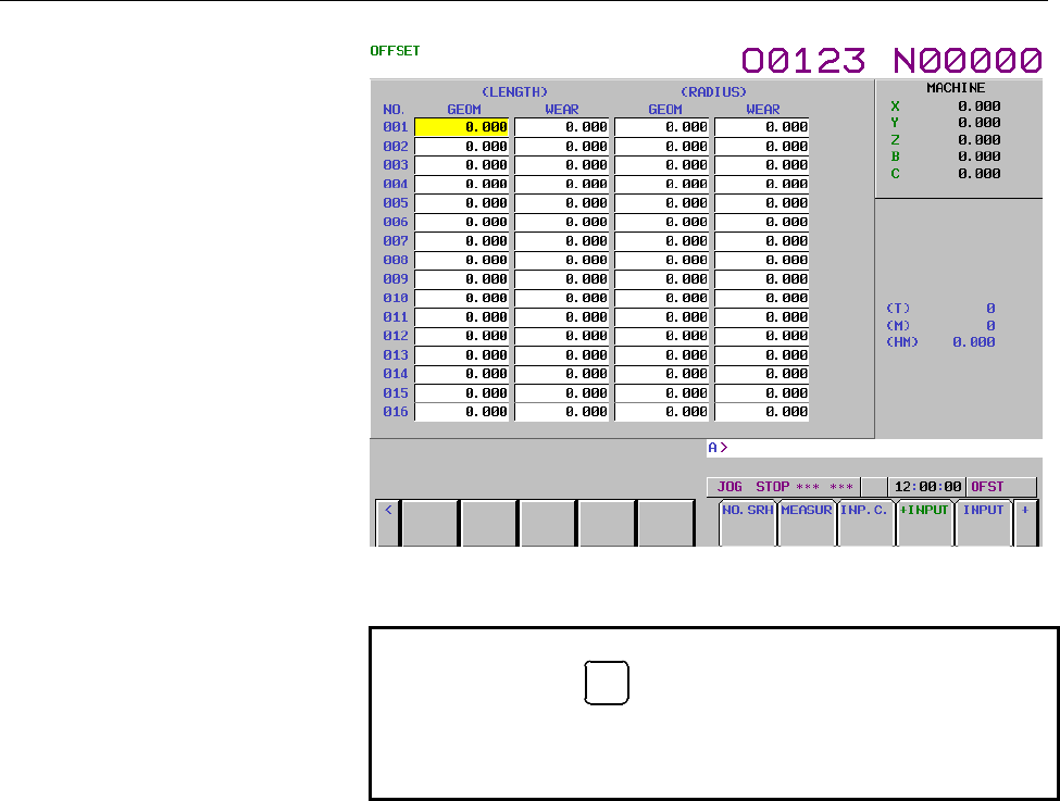
Fig. 1.1.3 (c) Tool length compensation measurement screen for tool
compensation memory C
NOTE
Pressing the
RESET
key resets the displayed T and M
addresses to 0. Once MEM or MDI mode has been
selected, however, the modal T and M codes are
displayed.
4 Use the numeric keys to enter the distance from the base
measurement surface to the measurement surface, then press soft
key [HM INPUT] to set the distance. For details of the
measurement surface and base measurement surface, see
Explanations, below.
5 Select the tool for which the tool length compensation value is to
be measured.
While "OFST" is blinking at the bottom of the tool length
compensation measurement screen, a T code or M code can be
specified in manual handle feed or jog feed mode (manual
numeric command). First, enter Ttttt (where tttt is a T code
number), then press the cycle start button on the machine
operator's panel or MDI panel. The Ttttt command is executed,
thus selecting the tool to be measured. Then, usually, enter the
M06 command to move the tool to the spindle position. Once the
tool for which the tool length compensation is to be measured
has been selected at the spindle position, position the cursor to
the tool offset number with which the tool length compensation
for the selected tool is to be stored. The positioning of the cursor
to the offset number is usually done by the operator. Some
machines, however, automatically position the cursor to an
appropriate tool offset number upon the completion of tool
selection, if bit 5 (QNI) of parameter No. 5005 is set to 1.
Contents Summary of 30i/300i/300is-MA, 31i/310i/310is-MA and A5, 32i/320i/320is-MA Users manual
- Page 1FANUC Series 30*/300*/300*s-MODEL A FANUC Series 31*/310*/310*s-MODEL A5 FANUC Series 31*/310*/310*s-MODEL A FANUC Series 32*/320*/320*s-MODEL A For Machining Center System USER’S MANUAL B-63944EN-2/02
- Page 2• No part of this manual may be reproduced in any form. • All specifications and designs are subject to change without notice. The export of this product is subject to the authorization of the government of the country from where the product is exported. In this manual we have tried as much as possi
- Page 3B-63944EN-2/02 SAFETY PRECAUTIONS SAFETY PRECAUTIONS This section describes the safety precautions related to the use of CNC units. It is essential that these precautions be observed by users to ensure the safe operation of machines equipped with a CNC unit (all descriptions in this section assume t
- Page 4SAFETY PRECAUTIONS B-63944EN-2/02 1.1 DEFINITION OF WARNING, CAUTION, AND NOTE This manual includes safety precautions for protecting the user and preventing damage to the machine. Precautions are classified into Warning and Caution according to their bearing on safety. Also, supplementary informati
- Page 5B-63944EN-2/02 SAFETY PRECAUTIONS 1.2 GENERAL WARNINGS AND CAUTIONS WARNING 1 Never attempt to machine a workpiece without first checking the operation of the machine. Before starting a production run, ensure that the machine is operating correctly by performing a trial run using, for example, the s
- Page 6SAFETY PRECAUTIONS B-63944EN-2/02 WARNING 5 The parameters for the CNC and PMC are factory-set. Usually, there is not need to change them. When, however, there is not alternative other than to change a parameter, ensure that you fully understand the function of the parameter before making any change
- Page 7B-63944EN-2/02 SAFETY PRECAUTIONS NOTE Programs, parameters, and macro variables are stored in nonvolatile memory in the CNC unit. Usually, they are retained even if the power is turned off. Such data may be deleted inadvertently, however, or it may prove necessary to delete all data from nonvolatil
- Page 8SAFETY PRECAUTIONS B-63944EN-2/02 1.3 WARNINGS AND CAUTIONS RELATED TO PROGRAMMING This section covers the major safety precautions related to programming. Before attempting to perform programming, read the supplied User’s Manual carefully such that you are fully familiar with their contents. WARNIN
- Page 9B-63944EN-2/02 SAFETY PRECAUTIONS WARNING 5 Constant surface speed control When an axis subject to constant surface speed control approaches the origin of the workpiece coordinate system, the spindle speed may become excessively high. Therefore, it is necessary to specify a maximum allowable speed.
- Page 10SAFETY PRECAUTIONS B-63944EN-2/02 WARNING 11 Programmable mirror image Note that programmed operations vary considerably when a programmable mirror image is enabled. 12 Compensation function If a command based on the machine coordinate system or a reference position return command is issued in compe
- Page 11B-63944EN-2/02 SAFETY PRECAUTIONS 1.4 WARNINGS AND CAUTIONS RELATED TO HANDLING This section presents safety precautions related to the handling of machine tools. Before attempting to operate your machine, read the supplied User’s Manual carefully, such that you are fully familiar with their content
- Page 12SAFETY PRECAUTIONS B-63944EN-2/02 WARNING 5 Disabled override If override is disabled (according to the specification in a macro variable) during threading, rigid tapping, or other tapping, the speed cannot be predicted, possibly damaging the tool, the machine itself, the workpiece, or causing injur
- Page 13B-63944EN-2/02 SAFETY PRECAUTIONS WARNING 10 Manual intervention If manual intervention is performed during programmed operation of the machine, the tool path may vary when the machine is restarted. Before restarting the machine after manual intervention, therefore, confirm the settings of the manua
- Page 14SAFETY PRECAUTIONS B-63944EN-2/02 1.5 WARNINGS RELATED TO DAILY MAINTENANCE WARNING 1 Memory backup battery replacement When replacing the memory backup batteries, keep the power to the machine (CNC) turned on, and apply an emergency stop to the machine. Because this work is performed with the power
- Page 15B-63944EN-2/02 SAFETY PRECAUTIONS WARNING 2 Absolute pulse coder battery replacement When replacing the memory backup batteries, keep the power to the machine (CNC) turned on, and apply an emergency stop to the machine. Because this work is performed with the power on and the cabinet open, only thos
- Page 16SAFETY PRECAUTIONS B-63944EN-2/02 WARNING 3 Fuse replacement Before replacing a blown fuse, however, it is necessary to locate and remove the cause of the blown fuse. For this reason, only those personnel who have received approved safety and maintenance training may perform this work. When replacin
- Page 17B-63944EN-2/02 TABLE OF CONTENTS TABLE OF CONTENTS SAFETY PRECAUTIONS............................................................................s-1 I. GENERAL 1 GENERAL ............................................................................................... 3 1.1 NOTES ON READING THIS MANUAL
- Page 18TABLE OF CONTENTS B-63944EN-2/02 5.1.13 Boring Cycle (G89) ................................................................................................71 5.1.14 Canned Cycle Cancel for Drilling (G80)................................................................73 5.1.15 Example for Using Canne
- Page 19B-63944EN-2/02 TABLE OF CONTENTS 6.9 THREE-DIMENSIONAL CUTTER COMPENSATION (G40, G41) ............ 198 6.10 TOOL COMPENSATION VALUES, NUMBER OF COMPENSATION VALUES, AND ENTERING VALUES FROM THE PROGRAM (G10) ....... 203 6.11 COORDINATE SYSTEM ROTATION (G68, G69).....................................
- Page 20
- Page 21I. GENERA
- Page 22
- Page 23B-63944EN-2/02 GENERAL 1.GENERAL 1 GENERAL This manual consists of the following parts: About this manual I. GENERAL Describes chapter organization, applicable models, related manuals, and notes for reading this manual. II. PROGRAMMING Describes each function: Format used to program functions in the
- Page 241.GENERAL GENERAL B-63944EN-2/02 Applicable models The models covered by this manual, and their abbreviations are : Model name Abbreviation FANUC Series 30i-MODEL A 30i –A Series 30i FANUC Series 300i-MODEL A 300i–A Series 300i FANUC Series 300is-MODEL A 300is–A Series 300is FANUC Series 31i-MODEL A
- Page 25B-63944EN-2/02 GENERAL 1.GENERAL Related manuals of Series 30i/300i/300is- MODEL A Series 31i/310i/310is- MODEL A Series 31i/310i/310is- MODEL A5 Series 32i/320i/320is- MODEL A The following table lists the manuals related to Series 30i/300i /300is- A, Series 31i/310i /310is-A, Series 31i/310i /310i
- Page 261.GENERAL GENERAL B-63944EN-2/02 Related manuals of SERVO MOTOR αis/αi/βis/βi series The following table lists the manuals related to SERVO MOTOR αis/αi/βis/βi series Table 2 Related manuals Specification Manual name number FANUC AC SERVO MOTOR αis series FANUC AC SERVO MOTOR αi series B-65262EN DES
- Page 27B-63944EN-2/02 GENERAL 1.GENERAL 1.1 NOTES ON READING THIS MANUAL CAUTION 1 The function of an CNC machine tool system depends not only on the CNC, but on the combination of the machine tool, its magnetic cabinet, the servo system, the CNC, the operator's panels, etc. It is too difficult to describe
- Page 28
- Page 29II. PROGRAMMIN
- Page 30
- Page 31B-63944EN-2/02 PROGRAMMING 1.GENERAL 1 GENERAL - 11 -
- Page 321.GENERAL PROGRAMMING B-63944EN-2/02 1.1 TOOL FIGURE AND TOOL MOTION BY PROGRAM Explanation - Machining using the end of cutter - Tool length compensation function Usually, several tools are used for machining one workpiece. The tools have different tool length. It is very troublesome to change the
- Page 33B-63944EN-2/02 PROGRAMMING 2.PREPARATORY FUNCTION (G FUNCTION) 2 PREPARATORY FUNCTION (G FUNCTION) A number following address G determines the meaning of the command for the concerned block. G codes are divided into the following two types. Type Meaning The G code is effective only in the block in w
- Page 342.PREPARATORY FUNCTION (G FUNCTION) PROGRAMMING B-63944EN-2/02 Explanation 1. When the clear state (parameter CLR (No. 3402#6)) is set at power-up or reset, the modal G codes are placed in the states described below. (1) The modal G codes are placed in the states marked with as indicated in Table. (
- Page 35B-63944EN-2/02 PROGRAMMING 2.PREPARATORY FUNCTION (G FUNCTION) Table 2(a) G code list G code Group Function G00 Positioning (rapid traverse) G01 Linear interpolation (cutting feed) G02 Circular interpolation CW or helical interpolation CW G03 01 Circular interpolation CCW or helical interpolation CC
- Page 362.PREPARATORY FUNCTION (G FUNCTION) PROGRAMMING B-63944EN-2/02 Table 2(a) G code list G code Group Function G40 Cutter or tool nose radius compensation : cancel Three-dimensional cutter compensation : cancel Cutter or tool nose radius compensation : left G41 Three-dimensional cutter compensation : l
- Page 37B-63944EN-2/02 PROGRAMMING 2.PREPARATORY FUNCTION (G FUNCTION) Table 2(a) G code list G code Group Function G66 Macro modal call A G66.1 12 Macro modal call B G67 Macro modal call A/B cancel G68 Coordinate system rotation start or 3-dimensional coordinate conversion mode on G69 16 Coordinate system
- Page 383.INTERPOLATION FUNCTION PROGRAMMING B-63944EN-2/02 3 INTERPOLATION FUNCTION - 18 -
- Page 39B-63944EN-2/02 PROGRAMMING 3.INTERPOLATION FUNCTION 3.1 INVOLUTE INTERPOLATION (G02.2, G03.2) Overview Involute curve machining can be performed by using involute interpolation. Cutter compensation can be performed. Involute interpolation eliminates the need for approximating an involute curve with
- Page 403.INTERPOLATION FUNCTION PROGRAMMING B-63944EN-2/02 Explanation Involute curve machining can be performed by using involute interpolation. Involute interpolation ensures continuous pulse distribution even in high-speed operation in small blocks, thus enabling smooth and high-speed machining. Moreove
- Page 41B-63944EN-2/02 PROGRAMMING 3.INTERPOLATION FUNCTION Y Involute curve Start point (X, Y) R θo θ (Xo, Yo) End point Base circle X Fig. 3.1 (b) Involute curve Involute curves on the Z-X plane and Y-Z plane are defined in the same way as an involute curve on the X-Y plane. - Start point and end point Th
- Page 423.INTERPOLATION FUNCTION PROGRAMMING B-63944EN-2/02 - Choosing from two types of involute curves When only a start point and I, J, and K data are given, two types of involute curves can be created. One type of involute curve extends towards the base circle, and the other extends away from the base c
- Page 43B-63944EN-2/02 PROGRAMMING 3.INTERPOLATION FUNCTION - Specifiable G codes The following G codes can be specified in involute interpolation mode: G04: Dwell G10: Programmable data input G17: X-Y plane selection G18: Z-X plane selection G19: Y-Z plane selection G65: Macro call G66: Macro modal call G6
- Page 443.INTERPOLATION FUNCTION PROGRAMMING B-63944EN-2/02 3.1.1 Automatic Speed Control for Involute Interpolation This function automatically overrides the programmed feedrate in two different ways during involute interpolation. With this function, a favorable cutting surface can be formed with high prec
- Page 45B-63944EN-2/02 PROGRAMMING 3.INTERPOLATION FUNCTION Inward offset OVR = Rcp/(Rcp + Rofs) × 100 Outward offset OVR = Rcp/(Rcp - Rofs) × 100 where, Rcp : Radius of curvature at the center of the tool of the involute curve passing through the center of the tool Rofs : Radius of the cutter - Clamping th
- Page 463.INTERPOLATION FUNCTION PROGRAMMING B-63944EN-2/02 3.1.2 Helical Involute Interpolation (G02.2, G03.2) As with arc helical involute interpolation, this function performs helical involute interpolation on the two axes involute interpolation and on up to four other axes simultaneously. Format Helical
- Page 47B-63944EN-2/02 PROGRAMMING 3.INTERPOLATION FUNCTION 3.1.3 Involute Interpolation on Linear Axis and Rotary Axis (G02.2, G03.2) By performing involute interpolation in the polar coordinate interpolation mode, involute cutting can be carried out. Cutting is performed along an involute curve drawn in t
- Page 483.INTERPOLATION FUNCTION PROGRAMMING B-63944EN-2/02 Example C (Imaginary axis) Path after tool compensation Programmed path N204 C-axis N205 Tool X-axis N201 N200 N202 Z-axis N203 Fig. 3.1 (e) Involute interpolation in the polar coordinate interpolation mode O0001 ; . . N010 T0101 ; . . N100 G90 G00
- Page 49B-63944EN-2/02 PROGRAMMING 3.INTERPOLATION FUNCTION Limitation - Number of involute curve turns Both the start point and end point must be within 100 turns from the point where the involute curve starts. An involute curve can be specified to make one or more turns in a single block. If the specified
- Page 503.INTERPOLATION FUNCTION PROGRAMMING B-63944EN-2/02 3.2 THREADING (G33) Straight threads with a constant lead can be cut. The position coder mounted on the spindle reads the spindle speed in real-time. The read spindle speed is converted to the feedrate per minute to feed the tool. Format Z G33IP_ F
- Page 51B-63944EN-2/02 PROGRAMMING 3.INTERPOLATION FUNCTION NOTE 1 The spindle speed is limited as follows : 1 ≤ spindle speed ≤ (Maximum feedrate) / (Thread lead) Spindle speed : min-1 Thread lead : mm or inch Maximum feedrate : mm/min or inch/min ; maximum command-specified feedrate for feed-per-minute mo
- Page 524.COORDINATE VALUE AND DIMENSION PROGRAMMING B-63944EN-2/02 4 COORDINATE VALUE AND DIMENSION This chapter contains the following topics. 4.1 POLAR COORDINATE COMMAND (G15, G16) - 32 -
- Page 53B-63944EN-2/02 PROGRAMMING 4.COORDINATE VALUE AND DIMENSION 4.1 POLAR COORDINATE COMMAND (G15, G16) The end point coordinate value can be input in polar coordinates (radius and angle). The plus direction of the angle is counterclockwise of the selected plane first axis + direction, and the minus dir
- Page 544.COORDINATE VALUE AND DIMENSION PROGRAMMING B-63944EN-2/02 - Setting the origin of the workpiece coordinate system as the origin of the polar coordinate system Specify the radius (the distance between the origin and the point) to be programmed with an absolute programming. The origin of the workpie
- Page 55B-63944EN-2/02 PROGRAMMING 4.COORDINATE VALUE AND DIMENSION - Specifying angles and a radius with absolute programmings N1 G17 G90 G16 ; Specifying the polar coordinate command and selecting the XY plane Setting the origin of the workpiece coordinate system as the origin of the polar coordinate syst
- Page 564.COORDINATE VALUE AND DIMENSION PROGRAMMING B-63944EN-2/02 - Optional chamfering and corner R Optional chamfering and corner R cannot be specified in polar coordinate mode. - 36 -
- Page 57B-63944EN-2/02 PROGRAMMING 5.FUNCTIONS TO SIMPLIFY PROGRAMMING 5 FUNCTIONS TO SIMPLIFY PROGRAMMING This chapter explains the following items: 5.1 CANNED CYCLE FOR DRILLING 5.2 RIGID TAPPING 5.3 OPTIONAL CHAMFERING AND CORNER R 5.4 INDEX TABLE INDEXING FUNCTION - 37 -
- Page 585.FUNCTIONS TO SIMPLIFY PROGRAMMING PROGRAMMING B-63944EN-2/02 5.1 CANNED CYCLE FOR DRILLING Overview Canned cycles for drilling make it easier for the programmer to create programs. With a canned cycle, a frequently-used machining operation can be specified in a single block with a G function; with
- Page 59B-63944EN-2/02 PROGRAMMING 5.FUNCTIONS TO SIMPLIFY PROGRAMMING Operation 1 Initial level Operation 2 Operation 6 Point R level Operation 5 Operation 3 Rapid traverse Operation 4 Feed Fig. 5.1 (a) Operation sequence of canned cycle for drilling - Positioning plane The positioning plane is determined
- Page 605.FUNCTIONS TO SIMPLIFY PROGRAMMING PROGRAMMING B-63944EN-2/02 Example Assume that the U, V and W axes be parallel to the X, Y, and Z axes respectively. This condition is specified by parameter No. 1022. G17 G81 Z _ _: The Z axis is used for drilling. G17 G81 W _ _: The W axis is used for drilling.
- Page 61B-63944EN-2/02 PROGRAMMING 5.FUNCTIONS TO SIMPLIFY PROGRAMMING - Return point level G98/G99 When the tool reaches the bottom of a hole, the tool may be returned to point R or to the initial level. These operations are specified with G98 and G99. The following illustrates how the tool moves when G98
- Page 625.FUNCTIONS TO SIMPLIFY PROGRAMMING PROGRAMMING B-63944EN-2/02 - Symbols in figures Subsequent sections explain the individual canned cycles. Figures in these Explanation use the following symbols: Positioning (rapid traverse G00) Cutting feed (linear interpolation G01) Manual feed Oriented spindle
- Page 63B-63944EN-2/02 PROGRAMMING 5.FUNCTIONS TO SIMPLIFY PROGRAMMING 5.1.1 High-Speed Peck Drilling Cycle (G73) This cycle performs high-speed peck drilling. It performs intermittent cutting feed to the bottom of a hole while removing chips from the hole. Format G73 X_ Y_ Z_ R_ Q_ F_ K_ ; X_ Y_ : Hole pos
- Page 645.FUNCTIONS TO SIMPLIFY PROGRAMMING PROGRAMMING B-63944EN-2/02 - Auxiliary function When the G73 code and an M code are specified in the same block, the M code is executed at the time of the first positioning operation. When K is used to specify the number of repeats, the M code is executed for the
- Page 65B-63944EN-2/02 PROGRAMMING 5.FUNCTIONS TO SIMPLIFY PROGRAMMING 5.1.2 Left-Handed Tapping Cycle (G74) This cycle performs left-handed tapping. In the left-handed tapping cycle, when the bottom of the hole has been reached, the spindle rotates clockwise. Format G74 X_ Y_ Z_ R_P_ F_ K_ ; X_ Y_ : Hole p
- Page 665.FUNCTIONS TO SIMPLIFY PROGRAMMING PROGRAMMING B-63944EN-2/02 the above note may not be considered. Refer to the manual provided by the machine tool builder. - Auxiliary function When the G74 command and an M code are specified in the same block, the M code is executed at the time of the first posi
- Page 67B-63944EN-2/02 PROGRAMMING 5.FUNCTIONS TO SIMPLIFY PROGRAMMING 5.1.3 Fine Boring Cycle (G76) The fine boring cycle bores a hole precisely. When the bottom of the hole has been reached, the spindle stops, and the tool is moved away from the machined surface of the workpiece and retracted. Format G76
- Page 685.FUNCTIONS TO SIMPLIFY PROGRAMMING PROGRAMMING B-63944EN-2/02 - Tool length compensation When a tool length compensation (G43, G44, or G49) is specified in the canned cycle for drilling, the offset is applied after the time of positioning to point R. Limitation - Axis switching Before the drilling
- Page 69B-63944EN-2/02 PROGRAMMING 5.FUNCTIONS TO SIMPLIFY PROGRAMMING 5.1.4 Drilling Cycle, Spot Drilling (G81) This cycle is used for normal drilling. Cutting feed is performed to the bottom of the hole. The tool is then retracted from the bottom of the hole in rapid traverse. Format G81 X_ Y_ Z_ R_ F_ K_
- Page 705.FUNCTIONS TO SIMPLIFY PROGRAMMING PROGRAMMING B-63944EN-2/02 Limitation - Axis switching Before the drilling axis can be changed, the canned cycle for drilling must be canceled. - Drilling In a block that does not contain X, Y, Z, R, or any other axes, drilling is not performed. - Cancel Do not sp
- Page 71B-63944EN-2/02 PROGRAMMING 5.FUNCTIONS TO SIMPLIFY PROGRAMMING 5.1.5 Drilling Cycle Counter Boring Cycle (G82) This cycle is used for normal drilling. Cutting feed is performed to the bottom of the hole. At the bottom, a dwell is performed, then the tool is retracted in rapid traverse. This cycle is
- Page 725.FUNCTIONS TO SIMPLIFY PROGRAMMING PROGRAMMING B-63944EN-2/02 - Tool length compensation When a tool length compensation (G43, G44, or G49) is specified in the canned cycle for drilling, the offset is applied after the time of positioning to point R. Limitation - Axis switching Before the drilling
- Page 73B-63944EN-2/02 PROGRAMMING 5.FUNCTIONS TO SIMPLIFY PROGRAMMING 5.1.6 Peck Drilling Cycle (G83) This cycle performs peck drilling. It performs intermittent cutting feed to the bottom of a hole while removing shavings from the hole. Format G83 X_ Y_ Z_ R_ Q_ F_ K_ ; X_ Y_ : Hole position data Z_ : The
- Page 745.FUNCTIONS TO SIMPLIFY PROGRAMMING PROGRAMMING B-63944EN-2/02 - Tool length compensation When a tool length compensation (G43, G44, or G49) is specified in the canned cycle for drilling, the offset is applied after the time of positioning to point R. Limitation - Axis switching Before the drilling
- Page 75B-63944EN-2/02 PROGRAMMING 5.FUNCTIONS TO SIMPLIFY PROGRAMMING 5.1.7 Small-Hole Peck Drilling Cycle An arbor with the overload torque detection function is used to retract the tool when the overload torque detection signal (skip signal) is detected during drilling. Drilling is resumed after the spin
- Page 765.FUNCTIONS TO SIMPLIFY PROGRAMMING PROGRAMMING B-63944EN-2/02 Explanations - Componet operations of the cycle * X- and Y-axis positioning * Positioning at point R along the Z–axis * Cutting along the Z-axis (first time, depth of cut Q, incremental) Retracting (bottom of hole → minimum clearance ∆,
- Page 77B-63944EN-2/02 PROGRAMMING 5.FUNCTIONS TO SIMPLIFY PROGRAMMING tip is between points R and Z. (The signal causes a retraction). For details, refer to the manual of the machine tool builder. NOTE When receiving overload torque detect signal while the tool is advancing, the tool will be retracted (cle
- Page 785.FUNCTIONS TO SIMPLIFY PROGRAMMING PROGRAMMING B-63944EN-2/02 When the skip signal is detected during the previous drilling operation: δ=d1% (parameter No.5164) When the skip signal is not detected during the previous drilling operation: δ=d2% (parameter No.5165) When the cutting feedrate reaches t
- Page 79B-63944EN-2/02 PROGRAMMING 5.FUNCTIONS TO SIMPLIFY PROGRAMMING - Feedrate override The feedrate override function works during cutting, retraction, and advancing in the cycle. - Custom macro interface The number of retractions made during cutting and the number of retractions made in response to the
- Page 805.FUNCTIONS TO SIMPLIFY PROGRAMMING PROGRAMMING B-63944EN-2/02 5.1.8 Tapping Cycle (G84) This cycle performs tapping. In this tapping cycle, when the bottom of the hole has been reached, the spindle is rotated in the reverse direction. Format G84 X_ Y_ Z_ R_P_ F_ K_ ; X_ Y_ : Hole position data Z_ :
- Page 81B-63944EN-2/02 PROGRAMMING 5.FUNCTIONS TO SIMPLIFY PROGRAMMING without specifying the number of repeats for K. For some machines, the above note may not be considered. Refer to the manual provided by the machine tool builder. - Auxiliary function When the G84 command and an M code are specified in t
- Page 825.FUNCTIONS TO SIMPLIFY PROGRAMMING PROGRAMMING B-63944EN-2/02 5.1.9 Boring Cycle (G85) This cycle is used to bore a hole. Format G85 X_ Y_ Z_ R_ F_ K_ ; X_ Y_ : Hole position data Z_ : The distance from point R to the bottom of the hole R_ : The distance from the initial level to point R level F_ :
- Page 83B-63944EN-2/02 PROGRAMMING 5.FUNCTIONS TO SIMPLIFY PROGRAMMING Limitation - Axis switching Before the drilling axis can be changed, the canned cycle for drilling must be canceled. - Drilling In a block that does not contain X, Y, Z, R, or any other axes, drilling is not performed. - Cancel Do not sp
- Page 845.FUNCTIONS TO SIMPLIFY PROGRAMMING PROGRAMMING B-63944EN-2/02 5.1.10 Boring Cycle (G86) This cycle is used to bore a hole. Format G86 X_ Y_ Z_ R_ F_ K_ ; X_ Y_ : Hole position data Z_ : The distance from point R to the bottom of the hole R_ : The distance from the initial level to point R level F_
- Page 85B-63944EN-2/02 PROGRAMMING 5.FUNCTIONS TO SIMPLIFY PROGRAMMING - Auxiliary function When the G86 command and an M code are specified in the same block, the M code is executed at the time of the first positioning operation. When K is used to specify the number of repeats, the M code is executed for t
- Page 865.FUNCTIONS TO SIMPLIFY PROGRAMMING PROGRAMMING B-63944EN-2/02 5.1.11 Back Boring Cycle (G87) This cycle performs accurate boring. Format G87 X_ Y_ Z_ R_ Q_ P_ F_ K_ ; X_ Y_ : Hole position data Z_ : The distance from point R to the bottom of the hole R_ : The distance from the initial level to poin
- Page 87B-63944EN-2/02 PROGRAMMING 5.FUNCTIONS TO SIMPLIFY PROGRAMMING - Auxiliary function When the G87 command and an M code are specified in the same block, the M code is executed at the time of the first positioning operation. When K is used to specify the number of repeats, the M code is executed for t
- Page 885.FUNCTIONS TO SIMPLIFY PROGRAMMING PROGRAMMING B-63944EN-2/02 Example M3 S500 ; Cause the spindle to start rotating. G90 G87 X300. Y-250. Position, bore hole 1. Z-150. R-120. Q5. Orient at the initial level, then shift by 5 mm. P1000 F120. ; Stop at point Z for 1 s. Y-550. ; Position, drill hole 2.
- Page 89B-63944EN-2/02 PROGRAMMING 5.FUNCTIONS TO SIMPLIFY PROGRAMMING 5.1.12 Boring Cycle (G88) This cycle is used to bore a hole. Format G88 X_ Y_ Z_ R_ P_ F_ K_ ; X_ Y_ : Hole position data Z_ : The distance from point R to the bottom of the hole R_ : The distance from the initial level to point R level
- Page 905.FUNCTIONS TO SIMPLIFY PROGRAMMING PROGRAMMING B-63944EN-2/02 - Auxiliary function When the G88 command and an M code are specified in the same block, the M code is executed at the time of the first positioning operation. When K is used to specify the number of repeats, the M code is executed for t
- Page 91B-63944EN-2/02 PROGRAMMING 5.FUNCTIONS TO SIMPLIFY PROGRAMMING 5.1.13 Boring Cycle (G89) This cycle is used to bore a hole. Format G89 X_ Y_ Z_ R_ P_ F_ K_ ; X_ Y_ : Hole position data Z_ : The distance from point R to the bottom of the hole R_ : The distance from the initial level to point R level
- Page 925.FUNCTIONS TO SIMPLIFY PROGRAMMING PROGRAMMING B-63944EN-2/02 Limitation - Axis switching Before the drilling axis can be changed, the canned cycle for drilling must be canceled. - Drilling In a block that does not contain X, Y, Z, R, or any other axes, drilling is not performed. - P Specify P in b
- Page 93B-63944EN-2/02 PROGRAMMING 5.FUNCTIONS TO SIMPLIFY PROGRAMMING 5.1.14 Canned Cycle Cancel for Drilling (G80) G80 cancels canned cycles for drilling. Format G80 ; Explanation All canned cycles for drilling are canceled to perform normal operation. Point R and point Z are cleared. Other drilling data
- Page 945.FUNCTIONS TO SIMPLIFY PROGRAMMING PROGRAMMING B-63944EN-2/02 5.1.15 Example for Using Canned Cycles for Drilling Offset value +200.0 is set in offset No.11, +190.0 is set in offset No.15, and +150.0 is set in offset No.31 Program example ; N001 G92 X0 Y0 Z0; Coordinate setting at reference positio
- Page 95B-63944EN-2/02 PROGRAMMING 5.FUNCTIONS TO SIMPLIFY PROGRAMMING Program using tool length offset and canned cycles Reference position 350 #1 #11 #6 100 #7 200 #10 100 #2 #12 #5 100 #8 #9 Y 200 100 #3 #13 #4 X 400 150 250 250 150 #1 to 6 Drilling of a 10 mm diameter hole #7 to 10 Drilling of a 20 mm d
- Page 965.FUNCTIONS TO SIMPLIFY PROGRAMMING PROGRAMMING B-63944EN-2/02 5.2 RIGID TAPPING The tapping cycle (G84) and left-handed tapping cycle (G74) may be performed in standard mode or rigid tapping mode. In standard mode, the spindle is rotated and stopped along with a movement along the tapping axis usin
- Page 97B-63944EN-2/02 PROGRAMMING 5.FUNCTIONS TO SIMPLIFY PROGRAMMING 5.2.1 Rigid Tapping (G84) When the spindle motor is controlled in rigid mode as if it were a servo motor, a tapping cycle can be sped up. Format G84 X_ Y_ Z_ R_ P_ F_ K_ ; X_ Y_ : Hole position data Z_ : The distance from point R to the
- Page 985.FUNCTIONS TO SIMPLIFY PROGRAMMING PROGRAMMING B-63944EN-2/02 - Rigid mode Rigid mode can be specified using any of the following methods: • Specify M29 S***** before a tapping command. • Specify M29 S***** in a block which contains a tapping command. • Specify G84 for rigid tapping (parameter G84
- Page 99B-63944EN-2/02 PROGRAMMING 5.FUNCTIONS TO SIMPLIFY PROGRAMMING - Reset When a reset is performed during rigid tapping, the rigid tapping mode is canceled and the spindle motor enters the normal mode. Note that the G84 (G74) mode is not canceled in this case when bit 6 (CLR) of parameter No. 3402 is
- Page 1005.FUNCTIONS TO SIMPLIFY PROGRAMMING PROGRAMMING B-63944EN-2/02 - Unit of F command Metric input Inch input Remarks Decimal point programming G94 1 mm/min 0.01 inch/min allowed Decimal point programming G95 0.01 mm/rev 0.0001 inch/rev allowed - M29 If an S command and axis movement are specified betw
- Page 101B-63944EN-2/02 PROGRAMMING 5.FUNCTIONS TO SIMPLIFY PROGRAMMING 5.2.2 Left-Handed Rigid Tapping Cycle (G74) When the spindle motor is controlled in rigid mode as if it were a servo motor, tapping cycles can be speed up. Format G74 X_ Y_ Z_ R_ P_ F_ K_ ; X_ Y_ : Hole position data Z_ : The distance fr
- Page 1025.FUNCTIONS TO SIMPLIFY PROGRAMMING PROGRAMMING B-63944EN-2/02 - Rigid mode Rigid mode can be specified using any of the following methods: • Specify M29 S***** before a tapping command. • Specify M29 S***** in a block which contains a tapping command. • Specify G74 for rigid tapping. (parameter G84
- Page 103B-63944EN-2/02 PROGRAMMING 5.FUNCTIONS TO SIMPLIFY PROGRAMMING - Reset When a reset is performed during rigid tapping, the rigid tapping mode is canceled and the spindle motor enters the normal mode. Note that the G84 (G74) mode is not canceled in this case when bit 6 (CLR) of parameter No. 3402 is
- Page 1045.FUNCTIONS TO SIMPLIFY PROGRAMMING PROGRAMMING B-63944EN-2/02 - Unit of F command Metric input Inch input Remarks Decimal point programming G94 1 mm/min 0.01 inch/min allowed Decimal point programming G95 0.01 mm/rev 0.0001 inch/rev allowed - M29 Specifying an S command or axis movement between M29
- Page 105B-63944EN-2/02 PROGRAMMING 5.FUNCTIONS TO SIMPLIFY PROGRAMMING 5.2.3 Peck Rigid Tapping Cycle (G84 or G74) Tapping a deep hole in rigid tapping mode may be difficult due to chips sticking to the tool or increased cutting resistance. In such cases, the peck rigid tapping cycle is useful. In this cycl
- Page 1065.FUNCTIONS TO SIMPLIFY PROGRAMMING PROGRAMMING B-63944EN-2/02 Explanation - High-speed peck tapping cycle After positioning along the X- and Y-axes, rapid traverse is performed to point R. From point R, cutting is performed with depth Q (depth of cut for each cutting feed), then the tool is retract
- Page 107B-63944EN-2/02 PROGRAMMING 5.FUNCTIONS TO SIMPLIFY PROGRAMMING - Reset When a reset is performed during rigid tapping, the rigid tapping mode is canceled and the spindle motor enters the normal mode. Note that the G84 (G74) mode is not canceled in this case when bit 6 (CLR) of parameter No. 3402 is
- Page 1085.FUNCTIONS TO SIMPLIFY PROGRAMMING PROGRAMMING B-63944EN-2/02 - Unit of F command Metric input Inch input Remarks Decimal point programming G94 1 mm/min 0.01 inch/min allowed Decimal point programming G95 0.01 mm/rev 0.0001 inch/rev allowed - M29 Specifying an S command or axis movement between M29
- Page 109B-63944EN-2/02 PROGRAMMING 5.FUNCTIONS TO SIMPLIFY PROGRAMMING 5.2.4 Canned Cycle Cancel (G80) The rigid tapping canned cycle is canceled. For how to cancel this cycle, see II-5.1.13. NOTE When the rigid tapping canned cycle is cancelled, the S value used for rigid tapping is also cleared (as if S0
- Page 1105.FUNCTIONS TO SIMPLIFY PROGRAMMING PROGRAMMING B-63944EN-2/02 5.2.5 Override during Rigid Tapping Various types of override functions are invalid. The following override functions can be enabled by setting corresponding parameters: • Extraction override • Override signal 5.2.5.1 Extraction override
- Page 111B-63944EN-2/02 PROGRAMMING 5.FUNCTIONS TO SIMPLIFY PROGRAMMING The override to be applied is determined according to the setting of parameters and that in the command as shown in the table below. Parameter setting DOV = 1 DOV = 0 Command OV3 = 1 OV3 = 0 Within the range between Command in Spindle sp
- Page 1125.FUNCTIONS TO SIMPLIFY PROGRAMMING PROGRAMMING B-63944EN-2/02 5.2.5.2 Override signal By setting bit 4 (OVS) of parameter No. 5203 to 1, override can be applied to cutting/extraction operation during rigid tapping as follows: • Applying override using the feedrate override signal (When the second f
- Page 113B-63944EN-2/02 PROGRAMMING 5.FUNCTIONS TO SIMPLIFY PROGRAMMING 5.3 OPTIONAL CHAMFERING AND CORNER R Overview Chamfering and corner R blocks can be inserted automatically between the following: • Between linear interpolation and linear interpolation blocks • Between linear interpolation and circular
- Page 1145.FUNCTIONS TO SIMPLIFY PROGRAMMING PROGRAMMING B-63944EN-2/02 Example N001 G92 G90 X0 Y0 ; N002 G00 X10.0 Y10.0 ; N003 G01 X50.0 F10.0 ,C5.0 ; N004 Y25.0 ,R8.0 ; N005 G03 X80.0 Y50.0 R30.0 ,R8.0 ; N006 G01 X50.0 ,R8.0 ; N007 Y70.0 ,C5.0 ; N008 X10.0 ,C5.0 ; N009 Y10.0 ; N010 G00 X0 Y0 ; N011 M0; Y
- Page 115B-63944EN-2/02 PROGRAMMING 5.FUNCTIONS TO SIMPLIFY PROGRAMMING - Exceeding the move range If the inserted chamfering or corner R block causes the tool to go beyond the original interpolation move range, alarm PS0055 is issued. G91 G01 X30.0 ; G03 X7.5 Y16.0 R37.0 ,C28.0 ; G03 X67.0 Y-27.0 R55.0 ; C
- Page 1165.FUNCTIONS TO SIMPLIFY PROGRAMMING PROGRAMMING B-63944EN-2/02 - Travel distance 0 When two linear interpolation operations are performed, the chamfering or corner R block is regarded as having a travel distance of zero if the angle between the two straight lines is within ±1°. When linear interpola
- Page 117B-63944EN-2/02 PROGRAMMING 5.FUNCTIONS TO SIMPLIFY PROGRAMMING 5.4 INDEX TABLE INDEXING FUNCTION By specifying indexing positions (angles) for the indexing axis (one rotation axis, A, B, or C), the index table of the machining center can be indexed. Before and after indexing, the index table is auto
- Page 1185.FUNCTIONS TO SIMPLIFY PROGRAMMING PROGRAMMING B-63944EN-2/02 - Direction and value of rotation The direction of rotation and angular displacement are determined by either of the following two methods. Refer to the manual written by the machine tool builder to find out which method is applied. 1. U
- Page 119B-63944EN-2/02 PROGRAMMING 5.FUNCTIONS TO SIMPLIFY PROGRAMMING NOTE 1 Specify the indexing command in a single block. If the command is specified in a block in which another controlled axis is specified, alarm PS0136 occurs. 2 The waiting state which waits for completion of clamping or unclamping of
- Page 1206.COMPENSATION FUNCTION PROGRAMMING B-63944EN-2/02 6 COMPENSATION FUNCTION 6.1 TOOL LENGTH COMPENSATION SHIFT TYPES 6.2 AUTOMATIC TOOL LENGTH MEASUREMENT (G37) 6.3 TOOL OFFSET (G45 TO G48) 6.4 OVERVIEW OF CUTTER COMPENSATION (G40-G42) 6.5 OVERVIEW OF TOOL NOSE RADIUS COMPENSATION (G40-G42) 6.6 DETAI
- Page 121B-63944EN-2/02 PROGRAMMING 6.COMPENSATION FUNCTION 6.1 TOOL LENGTH COMPENSATION SHIFT TYPES Overview A tool length compensation operation can be performed by shifting the program coordinate system: The coordinate system containing the axis subject to tool length compensation is shifted by the tool l
- Page 1226.COMPENSATION FUNCTION PROGRAMMING B-63944EN-2/02 - Tool length compensation B G17 G43 Z_H_; Shifts the coordinate system along the Z axis by the compensation value, to the + side. G17 G44 Z_H_; Shifts the coordinate system along the Z axis by the compensation value, to the - side. G18 G43 Y_H_; Sh
- Page 123B-63944EN-2/02 PROGRAMMING 6.COMPENSATION FUNCTION Explanation - Offset direction If the tool length compensation value specified with an H code (and stored in offset memory) is G43, the coordinate system is shifted to the + side; if G44, to the - side. If the sign of the tool length compensation va
- Page 1246.COMPENSATION FUNCTION PROGRAMMING B-63944EN-2/02 CAUTION 1 Specifying tool length compensation (a shift type) first and then executing an incremental programming causes the tool length compensation value to be reflected in the coordinates only, not in the travel distance of the machine; executing
- Page 125B-63944EN-2/02 PROGRAMMING 6.COMPENSATION FUNCTION CAUTION 10 If reference position return (G28, G30, or G30.1) has been specified, tool length compensation is canceled for the axis specified at the time of positioning on the reference point; however, tool length compensation is not canceled for an
- Page 1266.COMPENSATION FUNCTION PROGRAMMING B-63944EN-2/02 6.2 AUTOMATIC TOOL LENGTH MEASUREMENT (G37) By issuing G37 the tool starts moving to the measurement position and keeps on moving till the approach end signal from the measurement device is output. Movement of the tool is stopped when the tool nose
- Page 127B-63944EN-2/02 PROGRAMMING 6.COMPENSATION FUNCTION - Specifying G37 Specify the absolute coordinates of the correct measurement position. Execution of this command moves the tool at the rapid traverse rate toward the measurement position, reduces the federate halfway, then continuous to move it unti
- Page 1286.COMPENSATION FUNCTION PROGRAMMING B-63944EN-2/02 NOTE 1 When an H code is specified in the same block as G37, an alarm is generated. Specify H code before the block of G37. 2 The measurement speed (FP), γ, and ε are set as parameters (FP: No. 6241, γ: No. 6251, ε: No. 6254) by the machine tool bui
- Page 129B-63944EN-2/02 PROGRAMMING 6.COMPENSATION FUNCTION Example G92 Z760.0 X1100.0 ; Sets a workpiece coordinate system with respect to the programmed absolute zero point. G00 G90 X850.0 ; Moves the tool to X850.0. That is the tool is moved to a position that is a specified distance from the measurement
- Page 1306.COMPENSATION FUNCTION PROGRAMMING B-63944EN-2/02 6.3 TOOL OFFSET (G45 TO G48) The programmed travel distance of the tool can be increased or decreased by a specified tool offset value or by twice the offset value. The tool offset function can also be applied to an additional axis. Workpiece Tool c
- Page 131B-63944EN-2/02 PROGRAMMING 6.COMPENSATION FUNCTION Explanation - Increase and decrease As shown in Table 6.3 (a), the travel distance of the tool is increased or decreased by the specified tool offset value. In the absolute mode, the travel distance is increased or decreased as the tool is moved fro
- Page 1326.COMPENSATION FUNCTION PROGRAMMING B-63944EN-2/02 CAUTION 1 When G45 to G48 is specified to n axes (n=1-6) simultaneously in a motion block, offset is applied to all n axes. When the cutter is offset only for cutter radius or diameter in taper cutting, overcutting or undercutting occurs. Therefore,
- Page 133B-63944EN-2/02 PROGRAMMING 6.COMPENSATION FUNCTION NOTE 1 When the specified direction is reversed by decrease as shown in the figure below, the tool moves in the opposite direction. Movement of the Program command Start End position position Tool offset value Example G46 X2.50 ; Tool offset value E
- Page 1346.COMPENSATION FUNCTION PROGRAMMING B-63944EN-2/02 Example Program using tool offset N12 N11 30R N9 40 N10 N13 N8 N4 30R 40 N3 N5 N1 N2 N6 N7 Y axis 50 N14 80 50 40 30 30 X Origin Tool diameter : 20φ Offset No. : 01 Tool offset value : +10.0 Program N1 G91 G46 G00 X80.0 Y50.0 D01 ; N2 G47 G01 X50.0
- Page 135B-63944EN-2/02 PROGRAMMING 6.COMPENSATION FUNCTION 6.4 OVERVIEW OF CUTTER COMPENSATION (G40-G42) When the tool is moved, the tool path can be shifted by the radius of the tool (Fig. 6.4 (a)). To make an offset as large as the radius of the tool, CNC first creates an offset vector with a length equal
- Page 1366.COMPENSATION FUNCTION PROGRAMMING B-63944EN-2/02 Format - Start up (cutter compensation start) G00(or G01)G41(or G42) IP_D_; G41 : Cutter compensation left (Group 07) G42 : Cutter compensation right (Group 07) IP_ : Command for axis movement D_ : Code for specifying as the cutter compensation valu
- Page 137B-63944EN-2/02 PROGRAMMING 6.COMPENSATION FUNCTION - Offset mode cancel In the offset mode, when a block which satisfies any one of the following conditions is executed, the CNC enters the offset cancel mode, and the action of this block is called the offset cancel. 1. G40 has been commanded. 2. 0 h
- Page 1386.COMPENSATION FUNCTION PROGRAMMING B-63944EN-2/02 - Positive/negative cutter compensation value and tool center path If the compensation value is negative (–), distribution is made for a figure in which G41's and G42's are all replaced with each other on the program. Consequently, if the tool cente
- Page 139B-63944EN-2/02 PROGRAMMING 6.COMPENSATION FUNCTION - Valid compensation value range The valid range of values that can be set as a compensation value is either of the following, depending on the parameters OFE, OFD, OFC, and OFA (No. 5042 #3 to #0). Valid compensation range (metric input) OFE OFD OF
- Page 1406.COMPENSATION FUNCTION PROGRAMMING B-63944EN-2/02 Example 250R N5 C1(700,1300) P4(500,1150) P5(900,1150) C3 (-150,1150) C2 (1550,1150) 650R 650R N4 N6 N3 N7 P2 P3(450,900) P6(950,900) P7 (250,900) (1150,900) N8 N2 P9(700,650) P1 P8 (250,550) (1150,550) N10 N9 Y axis N1 N11 X axis Unit : mm Start po
- Page 141B-63944EN-2/02 PROGRAMMING 6.COMPENSATION FUNCTION G92 X0 Y0 Z0 ; .................................................. Specifies absolute coordinates. The tool is positioned at the start point (X0, Y0, Z0). N1 G90 G17 G00 G41 D07 X250.0 Y550.0 ; .............. Starts cutter compensation (start-up). Th
- Page 1426.COMPENSATION FUNCTION PROGRAMMING B-63944EN-2/02 6.5 OVERVIEW OF TOOL NOSE RADIUS COMPENSATION (G40-G42) The tool nose radius compensation function automatically compensates for the errors due to the tool nose roundness. Workpiece Tool path without compensation Tool path with compensation Insuffic
- Page 143B-63944EN-2/02 PROGRAMMING 6.COMPENSATION FUNCTION CAUTION In a machine with reference positions, a standard position like the turret center can be placed over the start point. The distance from this standard position to the tool nose radius center or the imaginary tool nose is compensated by the to
- Page 1446.COMPENSATION FUNCTION PROGRAMMING B-63944EN-2/02 6.5.2 Direction of Imaginary Tool Nose The direction of the imaginary tool nose viewed from the tool nose center is determined by the direction of the tool during cutting, so it must be set in advance as well as offset values. The direction of the i
- Page 145B-63944EN-2/02 PROGRAMMING 6.COMPENSATION FUNCTION Imaginary tool nose numbers 0 and 9 are used when the tool nose center coincides with the start point. Set imaginary tool nose number to address OFT for each offset number. Imaginary tool nose number 0 or 9 - 125 -
- Page 1466.COMPENSATION FUNCTION PROGRAMMING B-63944EN-2/02 6.5.3 Offset Number and Offset Value Explanation - Offset number and offset value Tool nose radius compensation value (Tool nose radius value) Table 6.5.3 (a) Offset number and offset value (example) Offset number (Tool compensation (Direction of im
- Page 147B-63944EN-2/02 PROGRAMMING 6.COMPENSATION FUNCTION 6.5.4 Workpiece Position and Move Command In tool nose radius compensation, the position of the workpiece with respect to the tool must be specified. G code Workpiece position Tool path G40 (Cancel) Moving along the programmed path Moving on the lef
- Page 1486.COMPENSATION FUNCTION PROGRAMMING B-63944EN-2/02 The workpiece position can be changed by setting the coordinate system as shown below. Z axis G41 (the workpiece is on the left side) X axis Workpiece G42 (the workpiece is on NOTE the right side) If the tool nose radius compensation value is negati
- Page 149B-63944EN-2/02 PROGRAMMING 6.COMPENSATION FUNCTION Explanation - Tool movement when the workpiece position does not change When the tool is moving, the tool nose maintains contact with the workpiece. (G42) (G42) (G42) (G42) (G42) (G42) Enlarged diagram Fig. 6.5.4 (c) Tool movement when the workpiece
- Page 1506.COMPENSATION FUNCTION PROGRAMMING B-63944EN-2/02 - Start-up The block in which the mode changes to G41 or G42 from G40 is called the start-up block. G40 _ ; G41 _ ; (Start-up block) Transient tool movements for offset are performed in the start-up block. In the block after the start-up block, the
- Page 151B-63944EN-2/02 PROGRAMMING 6.COMPENSATION FUNCTION - Changing the compensation value In general, the compensation value is to be changed when the tool is changed in offset cancel mode. If the compensation value is changed in offset mode, however, the vector at the end point of the block is calculate
- Page 1526.COMPENSATION FUNCTION PROGRAMMING B-63944EN-2/02 - Tool movement when the moving direction of the tool in a block which includes a G40 (offset cancel) command is different from the direction of the workpiece When you wish to retract the tool in the direction specified by X and Z canceling the tool
- Page 153B-63944EN-2/02 PROGRAMMING 6.COMPENSATION FUNCTION Example X <3> φ300 <1> <2> 200 φ60 Z 120 0 30 150 (G40 mode) <1> G42 G00 X60.0 ; <2> G01 X120.0 Z-150.0 F10 ; <3> G40 G00 X300.0 Z0 I40.0 K-30.0 ; - 133 -
- Page 1546.COMPENSATION FUNCTION PROGRAMMING B-63944EN-2/02 6.5.5 Notes on Tool Nose Radius Compensation Explanation - Blocks without a move command that are specified in offset mode <1> M05 ; M code output <2> S210 ; S code output <3> G04 X10.0 ; Dwell <4> G22 X100000 ; Machining area setting <5> G91 G01 X0
- Page 155B-63944EN-2/02 PROGRAMMING 6.COMPENSATION FUNCTION - Tool nose radius compensation when a corner R is performed Movement after compensation is shown below. (G42 mode) G91 G01 Z-20.0, R10.0; X20.0; (G42) Programmed path (G41) - 135 -
- Page 1566.COMPENSATION FUNCTION PROGRAMMING B-63944EN-2/02 6.6 DETAILS OF CUTTER OR TOOL NOSE RADIUS COMPENSATION 6.6.1 Overview The following explanation focuses on the cutter compensation, but applies to the tool nose radius compensation as well. - Inner side and outer side When an angle of intersection o
- Page 157B-63944EN-2/02 PROGRAMMING 6.COMPENSATION FUNCTION - Cancel mode The cutter compensation enters the cancel mode under the following conditions. (The system may not enter the cancel mode depending on the machine tool.) <1> Immediately after the power is turned on <2> When the
button on the MD - Page 1586.COMPENSATION FUNCTION PROGRAMMING B-63944EN-2/02 SUV SUP Type Operation 0 1 Type B A compensation vector is output, which is vertical to the start-up block and the cancel block. An intersection vector is also output. Intersection Tool center path Programmed path G41 N2 N1 1 0 Type C When the start
- Page 159B-63944EN-2/02 PROGRAMMING 6.COMPENSATION FUNCTION - Ending (canceling) cutter compensation In cutter compensation mode, cutter compensation is canceled if a block that satisfies at least either one of the following conditions is executed: <1> G40 is specified. <2> D00 is specified as the compensati
- Page 1606.COMPENSATION FUNCTION PROGRAMMING B-63944EN-2/02 6.6.2 Tool Movement in Start-up When the offset cancel mode is changed to offset mode, the tool moves as illustrated below (start-up): Explanation - Tool movement around an inner side of a corner (180°≤ α) Linear→Linear α Workpiece Programmed path r
- Page 161B-63944EN-2/02 PROGRAMMING 6.COMPENSATION FUNCTION - Cases in which the start-up block is a block with tool movement and the tool moves around the outside at an obtuse angle (90°≤ α<180°) Tool path in start-up has two types A and B, and they are selected by parameter SUP (No.5003#0). Linear→Linear S
- Page 1626.COMPENSATION FUNCTION PROGRAMMING B-63944EN-2/02 Linear→Linear Start point (Circular connection type) G42 α Workpiece L Programmed path r r C L S Tool center path Type B Linear→Circular Start point (Circular connection type) G42 α L r Workpiece r C S C Tool center path Programmed path - 142 -
- Page 163B-63944EN-2/02 PROGRAMMING 6.COMPENSATION FUNCTION - Cases in which the start-up block is a block with tool movement and the tool moves around the outside at an acute angle (α<90°) Tool path in start-up has two types A and B, and they are selected by parameter SUP (No.5003#0). Linear→Linear Start po
- Page 1646.COMPENSATION FUNCTION PROGRAMMING B-63944EN-2/02 Linear→Linear Start point (Circular L connection type) G42 Workpiece r α Programmed path r C S L Tool center path Type B Linear→Circular Start point (Circular L connection type) G42 r α r Work- C piece S C Tool center path Programmed path - Tool mov
- Page 165B-63944EN-2/02 PROGRAMMING 6.COMPENSATION FUNCTION - A block without tool movement specified at start-up For type A and B If the command is specified at start-up, the offset vector is not created. The tool does not operate in a start-up block. SS N7 S N6 N8 r Tool center path G40 … ; N6 X100.0 Y100.
- Page 1666.COMPENSATION FUNCTION PROGRAMMING B-63944EN-2/02 6.6.3 Tool Movement in Offset Mode In offset mode, compensation is performed even for positioning commands, not to speak of linear and circular interpolations. To perform intersection calculation, it is necessary to read at least two blocks with too
- Page 167B-63944EN-2/02 PROGRAMMING 6.COMPENSATION FUNCTION - Tool movement around the inside of a corner (180°≤ α) Linear→Linear α Workpiece Programmed path S L Tool center path Intersection L Linear→Circular α Work- piece Intersection S C L Tool center path Programmed path Circular→Linear α Workpiece Progr
- Page 1686.COMPENSATION FUNCTION PROGRAMMING B-63944EN-2/02 - Tool movement around the inside (α<1°) with an abnormally long vector, linear → linear Intersection r Tool center path Programmed path r r S Intersection Also in case of arc to straight line, straight line to arc and arc to arc, the reader should
- Page 169B-63944EN-2/02 PROGRAMMING 6.COMPENSATION FUNCTION - Tool movement around the outside corner at an obtuse angle (90°≤α<180°) Linear→Linear (Linear connection type) α Workpiece L Programmed path S Intersection L Tool center path Linear→Circular (Linear connection type) α Work- L r piece S L C Interse
- Page 1706.COMPENSATION FUNCTION PROGRAMMING B-63944EN-2/02 Linear→Linear (Circular connection type) α Workpiece L r Programmed path r C L S Tool center path Linear→Circular (Circular connection type) α r Work- L r piece C S C Tool center path Programmed path Circular→Linear (Circular connection type) α Work
- Page 171B-63944EN-2/02 PROGRAMMING 6.COMPENSATION FUNCTION - Tool movement around the outside corner at an acute angle (α<90°) Linear→Linear (Linear connection type) L Workpiece r α L Programmed path r L S L L Tool center path Linear→Circular (Linear connection type) L r α L Work- r piece L S L C Programmed
- Page 1726.COMPENSATION FUNCTION PROGRAMMING B-63944EN-2/02 Linear→Linear (Circular connection type) L Workpiece r α Programmed path r C S L Tool center path Linear→Circular (Circular connection type) L r α r Work- piece C S C Programmed path Tool center path Circular→Linear (Circular connection type) C Work
- Page 173B-63944EN-2/02 PROGRAMMING 6.COMPENSATION FUNCTION - When it is exceptional End point for the arc is not on the arc If the end of a line leading to an arc is not on the arc as illustrated below, the system assumes that the cutter compensation has been executed with respect to an imaginary circle tha
- Page 1746.COMPENSATION FUNCTION PROGRAMMING B-63944EN-2/02 - When the center of the arc is identical with the start point or the end point If the center of the arc is identical with the start point or end point, PS0041 is displayed, and the tool will stop at the start point of the preceding block of the arc
- Page 175B-63944EN-2/02 PROGRAMMING 6.COMPENSATION FUNCTION - Tool center path with an intersection Linear→Linear Workpiece S G42 L Intersection r Programmed path r L G41 Tool center path Workpiece Linear→Circular C r Workpiece G41 G42 Programmed path r Workpiece Intersection Tool center path L S Circular→Li
- Page 1766.COMPENSATION FUNCTION PROGRAMMING B-63944EN-2/02 - Tool center path without an intersection When changing the offset direction in block A to block B using G41 and G42, if intersection with the offset path is not required, the vector normal to block B is created at the start point of block B. Linea
- Page 177B-63944EN-2/02 PROGRAMMING 6.COMPENSATION FUNCTION - The length of tool center path larger than the circumference of a circle Normally there is almost no possibility of generating this situation. However, when G41 and G42 are changed, or when a G40 was commanded with address I, J, and K this situati
- Page 1786.COMPENSATION FUNCTION PROGRAMMING B-63944EN-2/02 - Cutter compensation G code in the offset mode The offset vector can be set to form a right angle to the moving direction in the previous block, irrespective of machining inner or outer side, by commanding the cutter compensation G code (G41, G42)
- Page 179B-63944EN-2/02 PROGRAMMING 6.COMPENSATION FUNCTION - Command canceling the offset vector temporarily During offset mode, if G92 (workpiece coordinate system setting) or G52 (local coordinate system setting) is commanded, the offset vector is temporarily cancelled and thereafter offset mode is automa
- Page 1806.COMPENSATION FUNCTION PROGRAMMING B-63944EN-2/02 - If I, J, and K are specified in a G00/G01 mode block At the start of cutter compensation or in that mode, by specifying I, J, and K in a positioning mode (G00) or linear interpolation mode (G01) block, it is possible to set the compensation vector
- Page 181B-63944EN-2/02 PROGRAMMING 6.COMPENSATION FUNCTION Example If I and J are specified at the start of compensation (with tool movement) N50 N40 (G40) N30 N10 G91 G41 X100.0 Y100.0 N20 N60 I1 D1 ; N20 G04 X1000 ; D1 Tool center path N30 G01 F1000 ; N10 N40 S300 ; N50 M50 ; Programmed path N60 X150. ; N
- Page 1826.COMPENSATION FUNCTION PROGRAMMING B-63944EN-2/02 If I and J are specified in a block without tool movement in compensation mode N30 N40 Tool center S S path Start-up/cancel type C N20 N50 N10 G41 D1 G01 F1000 ; (I, J) N20 G91 X100. Y100. ; N30 I10. ; Programmed path N40 X150. ; N50 G40 ; N10 D1 Li
- Page 183B-63944EN-2/02 PROGRAMMING 6.COMPENSATION FUNCTION - A block without tool movement specified in offset mode Unless the number of blocks without movement consecutively specified is more than N-2 blocks (where N is the number of blocks to read in offset mode (parameter No. 19625)) in offset mode, the
- Page 1846.COMPENSATION FUNCTION PROGRAMMING B-63944EN-2/02 - If an M/G code that suppresses buffering is specified If an M/G code that suppresses buffering is specified in offset mode, it is no longer possible to read and analyze subsequent blocks regardless of the number of blocks to read in offset mode, w
- Page 185B-63944EN-2/02 PROGRAMMING 6.COMPENSATION FUNCTION - Corner movement When two or more offset vectors are produced at the end of a block, the tool moves linearly from one vector to another. This movement is called the corner movement. If these vectors almost coincide with each other (the distance of
- Page 1866.COMPENSATION FUNCTION PROGRAMMING B-63944EN-2/02 The reason for this is as follows: P2 P3 P4 P5 N4 G41 G91 G01 X150.0 Y200.0 ; N5 X150.0 Y200.0 ; N6 G02 J-600.0 ; N7 G01 X150.0 Y-200.0 ; P1 P6 N8 G40 X150.0 Y-200.0 ; N5 N7 N4 N8 Programmed path N6 Tool center path If the vector is not ignored, the
- Page 187B-63944EN-2/02 PROGRAMMING 6.COMPENSATION FUNCTION 6.6.4 Tool Movement in Offset Mode Cancel Explanation - If the cancel block is a block with tool movement, and the tool moves around the inside (180° ≤ α) Linear→Linear Workpiece α Programmed path r G40 Tool center path L S L Circular→Linear α Work-
- Page 1886.COMPENSATION FUNCTION PROGRAMMING B-63944EN-2/02 - If the cancel block is a block with tool movement, and the tool moves around the outside at an obtuse angle (90° ≤ α < 180°) Tool path has two types A and B, and they are selected by parameter SUP (No.5003#0). Linear→Linear G40 Workpiece α Program
- Page 189B-63944EN-2/02 PROGRAMMING 6.COMPENSATION FUNCTION Linear→Linear (Circular connection type) G40 Workpiece α L Programmed path r C S Tool center path Type B Circular→Linear (Circular connection type) G40 α L Work- r piece r C S C Programmed path Tool center path - 169 -
- Page 1906.COMPENSATION FUNCTION PROGRAMMING B-63944EN-2/02 - If the cancel block is a block with tool movement, and the tool moves around the outside at an acute angle (α<90°) Tool path has two types A and B, and they are selected by parameter SUP (No.5003#0). Linear→Linear G40 Workpiece L α Programmed path
- Page 191B-63944EN-2/02 PROGRAMMING 6.COMPENSATION FUNCTION Linear→Linear (Circular connection type) L S Workpiece G40 α r Programmed path r C Tool center path L Type B Circular→Linear (Circular L connection type) S α r C Work- r piece C S Tool center path Programmed path - If the cancel block is a block wit
- Page 1926.COMPENSATION FUNCTION PROGRAMMING B-63944EN-2/02 - A block without tool movement specified together with offset cancel For types A and B In the block preceding the cancel block, a vector is created with a size equal to the cutter or tool nose radius compensation value in the vertical direction. Th
- Page 193B-63944EN-2/02 PROGRAMMING 6.COMPENSATION FUNCTION - Block containing G40 and I_J_K_ The previous block contains G41 or G42 If a G41 or G42 block precedes a block in which G40 and I_, J_, K_ are specified, the system assumes that the path is programmed as a path from the end point determined by the
- Page 1946.COMPENSATION FUNCTION PROGRAMMING B-63944EN-2/02 - Length of the tool center path larger than the circumference of a circle In the Example shown below, the tool does not trace the circle more than once. It moves along the arc from P1 to P2. The interference check function described below may raise
- Page 195B-63944EN-2/02 PROGRAMMING 6.COMPENSATION FUNCTION 6.6.5 Prevention of Overcutting Due to Cutter or Tool Nose Radius Compensation Explanation - Machining a groove smaller than the diameter of the tool Since the cutter compensation forces the tool center path to move in the reverse of the programmed
- Page 1966.COMPENSATION FUNCTION PROGRAMMING B-63944EN-2/02 - Machining a step smaller than the tool radius For a figure in which a workpiece step is specified with an arc, the tool center path will be as shown in Fig. 6.6.5 (b). If the step is smaller than the tool radius, the tool center path usually compe
- Page 197B-63944EN-2/02 PROGRAMMING 6.COMPENSATION FUNCTION - Starting compensation and cutting along the Z-axis It is usually used such a method that the tool is moved along the Z axis after the cutter compensation (normally XY plane) is effected at some distance from the workpiece at the start of the machi
- Page 1986.COMPENSATION FUNCTION PROGRAMMING B-63944EN-2/02 In such a case, it is possible to prevent overcutting by specifying a command with the exactly the same direction as the advance direction immediately before movement along the Z axis beforehand, after the tool is moved along the Z axis using the ab
- Page 199B-63944EN-2/02 PROGRAMMING 6.COMPENSATION FUNCTION 6.6.6 Interference Check Tool overcutting is called interference. The interference check function checks for tool overcutting in advance. However, all interference cannot be checked by this function. The interference check is performed even if overc
- Page 2006.COMPENSATION FUNCTION PROGRAMMING B-63944EN-2/02 - Interference reference <1> (direction check) Assuming the number of blocks to read during cutter compensation to be N, a check is first performed on the compensation vector group calculated in (block 1 - block 2) to be output this time and the com
- Page 201B-63944EN-2/02 PROGRAMMING 6.COMPENSATION FUNCTION Example of interference standard <1> (If the block 1 end-point vector intersects with the block 2 end-point vector) Programmed path Tool center path Block 1 The directions of these two paths are different (180°). Block 2 - Interference reference <2>
- Page 2026.COMPENSATION FUNCTION PROGRAMMING B-63944EN-2/02 - When interference is assumed although actual interference does not occur <1> Depression which is smaller than the cutter or tool nose radius compensation value Programmed path Tool center path Stopped A C B There is no actual interference, but sin
- Page 203B-63944EN-2/02 PROGRAMMING 6.COMPENSATION FUNCTION 6.6.6.1 Operation to be performed if an interference is judged to occur The operation to be performed if an interference check judges that an interference (due to overcutting) occurs can be either of the following two, depending on the setting of pa
- Page 2046.COMPENSATION FUNCTION PROGRAMMING B-63944EN-2/02 6.6.6.2 Interference check alarm function - Interference other than those between adjacent three blocks If the end-point vector of block 1 and the end-point vector of block 7 are judged to interfere as shown in the figure, an alarm will occur before
- Page 205B-63944EN-2/02 PROGRAMMING 6.COMPENSATION FUNCTION - Interference between adjacent three blocks If an interference is judged to occur between adjacent three blocks, the interfering vector, as well as any vectors existing inside of it, is erased, and a path is created to connect the remaining vectors
- Page 2066.COMPENSATION FUNCTION PROGRAMMING B-63944EN-2/02 6.6.6.3 Interference check avoidance function Overview If a command is specified which satisfies the condition under which the interference check alarm function generates an interference alarm, this function suppresses the generation of the interfer
- Page 207B-63944EN-2/02 PROGRAMMING 6.COMPENSATION FUNCTION If the post-compensation intersection vector of (block 1 - gap vector) and the post-compensation intersection vector of (gap vector - block N) further intersect, vector erasure is first performed in the same way as in "Interference between adjacent
- Page 2086.COMPENSATION FUNCTION PROGRAMMING B-63944EN-2/02 If the cutter or tool nose radius compensation value is greater than the radius of the specified arc as shown in the figure below, and a command is specified which results in compensation with respect to the inside of the arc, interference is avoide
- Page 209B-63944EN-2/02 PROGRAMMING 6.COMPENSATION FUNCTION - If no interference avoidance vector exists If the parallel pocket shown in the figure is to be machined, the end-point vector of block 1 and the end-point vector of block 2 are judged to interfere, and an attempt is made to calculate, as an interf
- Page 2106.COMPENSATION FUNCTION PROGRAMMING B-63944EN-2/02 Programmed path Tool center path Stopped Block 1 Block 3 Block 2 - If it is judged dangerous to avoid interference If the acute-angle pocket shown in the figure is to be machined, the end-point vector of block 1 and the end-point vector of block 2 a
- Page 211B-63944EN-2/02 PROGRAMMING 6.COMPENSATION FUNCTION blocks 1 and 3 is judged an outer one, the post-avoidance path results in overcutting as compared with the original command. In such a case, interference avoidance operation is judge dangerous; an alarm will occur immediately before block 1 and the
- Page 2126.COMPENSATION FUNCTION PROGRAMMING B-63944EN-2/02 NOTE 1 For "If it is judged dangerous to avoid interference" and "If further interference with an interference avoidance vector occurs", by setting parameter NAA (No. 19607#6) appropriately, it is possible to suppress an alarm to continue machining.
- Page 213B-63944EN-2/02 PROGRAMMING 6.COMPENSATION FUNCTION 6.6.7 Cutter or Tool Nose Radius Compensation for Input from MDI Explanation - MDI operation During MDI operation, that is, if a program command is specified in MDI mode in the reset state to make a cycle start, intersection calculation is performed
- Page 2146.COMPENSATION FUNCTION PROGRAMMING B-63944EN-2/02 - MDI intervention If MDI intervention is performed, that is, if a single block stop is performed to enter the automatic operation stop state in the middle of memory operation, DNC operation, and the like, and a program command is specified in MDI m
- Page 215B-63944EN-2/02 PROGRAMMING 6.COMPENSATION FUNCTION 6.7 VECTOR RETENTION (G38) In cutter or tool nose radius compensation, by specifying G38 in offset mode, it is possible to retain the compensation vector at the end point of the previous block, without performing intersection calculation. Format (In
- Page 2166.COMPENSATION FUNCTION PROGRAMMING B-63944EN-2/02 6.8 CORNER CIRCULAR INTERPOLATION (G39) By specifying G39 in offset mode during cutter or tool nose radius compensation, corner circular interpolation can be performed. The radius of the corner circular interpolation equals the compensation value. F
- Page 217B-63944EN-2/02 PROGRAMMING 6.COMPENSATION FUNCTION Example - G39 without I, J, or K : : (In offset mode) (G90) Y axis N1 X10.0 ; N2 G39 ; N3 Y-10.0 ; : : X axis Block N1 Offset vector Block N2 (Corner arc) (10.0, 0.0) Block N3 Programmed path Tool center path (10.0, -10.0) - G39 with I, J, and K : :
- Page 2186.COMPENSATION FUNCTION PROGRAMMING B-63944EN-2/02 6.9 THREE-DIMENSIONAL CUTTER COMPENSATION (G40, G41) In cutter compensation C, two-dimensional offsetting is performed for a selected plane. In three-dimensional cutter compensation, the tool can be shifted three-dimensionally when a three-dimension
- Page 219B-63944EN-2/02 PROGRAMMING 6.COMPENSATION FUNCTION - Selecting offset space The three-dimensional space where three-dimensional cutter compensation is to be executed is determined by the axis addresses specified in the startup block containing the G41 command. If Xp, Yp, or Zp is omitted, the corres
- Page 2206.COMPENSATION FUNCTION PROGRAMMING B-63944EN-2/02 - Relationship between three-dimensional cutter compensation and other compensation functions The specified path is shifted by three-dimensional cutter Tool length compensation and the subsequent path is shifted by tool compensation length compensat
- Page 221B-63944EN-2/02 PROGRAMMING 6.COMPENSATION FUNCTION - Return to a reference position (G28, G30, G30.1) When return to the reference position (G28), to the second, third, or fourth reference position (G30), or to the floating reference position (G30.1) is specified, the vector is cleared at a middle p
- Page 2226.COMPENSATION FUNCTION PROGRAMMING B-63944EN-2/02 - Commands that generate the same vector as the vector in the previous block When one of the following G codes is specified in three-dimensional cutter compensation mode, the same vector as the vector generated in the previous block is generated at
- Page 223B-63944EN-2/02 PROGRAMMING 6.COMPENSATION FUNCTION 6.10 TOOL COMPENSATION VALUES, NUMBER OF COMPENSATION VALUES, AND ENTERING VALUES FROM THE PROGRAM (G10) Tool compensation values include tool geometry compensation values and tool wear compensation (Fig. 6.10 (a)). Reference position OFSG OFSW OFSG
- Page 2246.COMPENSATION FUNCTION PROGRAMMING B-63944EN-2/02 - Tool compensation memory B In tool compensation memory B, memory for geometry compensation and memory for wear compensation are prepared separately. So, geometry compensation values and wear compensation values can be set separately. However, no d
- Page 225B-63944EN-2/02 PROGRAMMING 6.COMPENSATION FUNCTION - Number of tool compensation data items The number of tool compensation data items used by the entire system varies from one machine to another. Refer to the relevant manual of the machine tool builder. Format The format for programming depends on
- Page 2266.COMPENSATION FUNCTION PROGRAMMING B-63944EN-2/02 NOTE 1 Address R follows the increment system for tool offset values. 2 If L is omitted for compatibility with the conventional CNC format, or L1 is specified, the same operation as when L11 is specified is performed. 3 Set a imaginary tool nose num
- Page 227B-63944EN-2/02 PROGRAMMING 6.COMPENSATION FUNCTION 6.11 COORDINATE SYSTEM ROTATION (G68, G69) A programmed shape can be rotated. By using this function it becomes possible, for example, to modify a program using a rotation command when a workpiece has been placed with some angle rotated from the pro
- Page 2286.COMPENSATION FUNCTION PROGRAMMING B-63944EN-2/02 X Angle of rotation R (incremental value) Center of Angle of rotation (absolute value) rotation (α, β) Z Fig. 6.11 (b) Coordinate system rotation NOTE When a decimal fraction is used to specify angular displacement (R_), the 1's digit corresponds to
- Page 229B-63944EN-2/02 PROGRAMMING 6.COMPENSATION FUNCTION - Relationship with three-dimensional coordinate conversion (G68, G69) Both coordinate system rotation and three-dimensional coordinate conversion use the same G codes: G68 and G69. The G code with I, J, and K is processed as a command for three-dim
- Page 2306.COMPENSATION FUNCTION PROGRAMMING B-63944EN-2/02 Explanation - Absolute/Incremental position commands N1 G92 X*5000 Y*5000 G69 G17 ; N2 G68 X7000 Y3000 R60000 ; N3 G90 G01 X0 Y0 F200 ; (G91X5000Y5000) N4 G91 X10000 ; N5 G02 Y10000 R10000 ; N6 G03 X*10000 I*5000 J*5000 ; N7 G01 Y*10000 ; N8 G69 G90
- Page 231B-63944EN-2/02 PROGRAMMING 6.COMPENSATION FUNCTION - Scaling and coordinate system rotation If a coordinate system rotation command is executed in the scaling mode (G51 mode), the coordinate value (a,b,) of the rotation center will also be scaled, but not the rotation angle (R). When a move command
- Page 2326.COMPENSATION FUNCTION PROGRAMMING B-63944EN-2/02 2. When the system is in cutter compensation, specify the commands in the following order (Fig.6.11(e)) : (cutter compensation cancel) G51 ; Scaling mode start G68 ; Coordinate system rotation start : G41 ; Cutter compensation mode start : G92 X0 Y0
- Page 233B-63944EN-2/02 PROGRAMMING 6.COMPENSATION FUNCTION - Repetitive commands for coordinate system rotation It is possible to store one program as a subprogram and recall subprogram by changing the angle. Sample program for when the RIN bit (bit 0 of parameter 5400) is set to 1. The specified angular di
- Page 2346.COMPENSATION FUNCTION PROGRAMMING B-63944EN-2/02 6.12 ACTIVE OFFSET VALUE CHANGE FUNCTION BASED ON MANUAL FEED Overview When rough machining/semifinish machining is to be performed using a single tool, you may make a fine adjustment of a tool length compensation value or cutter compensation value.
- Page 235B-63944EN-2/02 PROGRAMMING 6.COMPENSATION FUNCTION CAUTION When a movement is being made on an axis for which an offset value is to be changed in the active offset value change mode, do not change the specification of the offset value to be changed. - Changing a tool length compensation value The to
- Page 2366.COMPENSATION FUNCTION PROGRAMMING B-63944EN-2/02 compensation value is being changed, a movement by manual feed can be made on one axis only. When operation is stopped in the cutter compensation mode to make a cutter compensation value change, a movable travel distance on one axis is added, regard
- Page 237B-63944EN-2/02 PROGRAMMING 6.COMPENSATION FUNCTION Example - Specified workpiece coordinate system : G56 - Workpiece origin offset of G56 (X axis) : 50.000 - Workpiece origin offset of G56 (Y axis) : -60.000 - Workpiece origin offset of G56 (Z axis) : 5.000 - Workpiece origin offset of G56 (A axis)
- Page 2386.COMPENSATION FUNCTION PROGRAMMING B-63944EN-2/02 - Presetting the relative position indication By setting bit 5 (APL) of parameter No. 3115 to 1, the relative position indication (counter) can be automatically preset to 0 when the active offset value change mode is selected. In this case, the chan
- Page 239B-63944EN-2/02 PROGRAMMING 6.COMPENSATION FUNCTION 6.13 ROTARY TABLE DYNAMIC FIXTURE OFFSET The rotary table dynamic fixture offset function saves the operator the trouble of resetting the workpiece coordinate system when the rotary table rotates before cutting is started. With this function the ope
- Page 2406.COMPENSATION FUNCTION PROGRAMMING B-63944EN-2/02 NOTE 1 In the G54.2 mode, a change made to the setting of parameter or to the reference fixture offset becomes effective when the next G54.2Pn is specified. 2 It depends on the current continuous–state code of the 01 group whether a change in the fi
- Page 241B-63944EN-2/02 PROGRAMMING 6.COMPENSATION FUNCTION - Data setting (1) Setting a group of three parameters which specify one rotation axis and two linear axes constituting the plane of rotation (Parameter No.7580 to 7588) In each group, specify the number of the rotation axis as the first parameter a
- Page 2426.COMPENSATION FUNCTION PROGRAMMING B-63944EN-2/02 - Input/output of fixture offset The data can be programmed and can be input from and output to external equipment, as described below: (1) Setting the reference fixture offset by G10 G10 L21 Pn P ; N: Refernece fixture offset number P: Reference fi
- Page 243B-63944EN-2/02 PROGRAMMING 6.COMPENSATION FUNCTION - Calculating a Fixture Offset values (1) Relationship between the rotation axes and linear axes First group : 4 (B-axis) , 3 (Z-axis) , 1 (X-axis) Second group : 5 (C-axis) , 1 (X-axis) , 2 (Y-axis) Third group :0 , 0 , 0 (2) Reference angle and re
- Page 2446.COMPENSATION FUNCTION PROGRAMMING B-63944EN-2/02 When N3 is executed with ABS(No.7570#1) is set to ‘1’. programmed coordninate value of C-axis is used for calculation directly as 40.0(10.0+30.0). Limitation - Command for suppressing fixture offset calculation If the following commands are specifie
- Page 245B-63944EN-2/02 PROGRAMMING 6.COMPENSATION FUNCTION Table 6.13 Example of fixture offset Coordinates Position on the Position on the Fixture offset workpiece coordinate machine coordinate system (ABSOLUTE) system (MACHINE) Program X Y C X Y C X Y C N1 G90 G00 X0 Y0 C90. ; 0.0 0.0 90.0 0.0 0.0 90.0 0.
- Page 2466.COMPENSATION FUNCTION PROGRAMMING B-63944EN-2/02 6.14 NORMAL DIRECTION CONTROL (G40.1, G41.1, G42.1) Overview When a tool with a rotation axis (C-axis) is moved in the XY plane during cutting, the normal direction control function can control the tool so that the C-axis is always perpendicular to
- Page 247B-63944EN-2/02 PROGRAMMING 6.COMPENSATION FUNCTION Cutter center path Cutter center path Programmed path Center of the arc Programmed path Fig. 6.14 (b) Normal direction control left (G41.1) Fig. 6.14 (c) Normal direction control right (G42.1) Explanation - Angle of the C axis When viewed from the c
- Page 2486.COMPENSATION FUNCTION PROGRAMMING B-63944EN-2/02 Y-axes. A single-block stop always occurs after the tool is moved along the X- and Y-axes. Cutter center path S N1 S : Single block stop point Programmed path N2 S N3 S Fig. 6.14 (e) Point at which a single-block stop occurs in the normal direction
- Page 249B-63944EN-2/02 PROGRAMMING 6.COMPENSATION FUNCTION The federate of the C axis during circular interpolation is defined by the following formula. Amount of movement of the C axis (deg) F× [deg/min] Length of arc (mm or inch) F : Federate (mm/min or inch/min) specified by the corresponding block of th
- Page 2506.COMPENSATION FUNCTION PROGRAMMING B-63944EN-2/02 • Circular movement When the diameter of block N2, shown below, is smaller than the set value, machining for block N2 is performed using the same normal direction as that for block N1. The orientation of the axis to which normal-direction control is
- Page 251B-63944EN-2/02 PROGRAMMING 7.MEMORY OPERATION USING Series 15 PROGRAM FORMAT 7 MEMORY OPERATION USING Series 15 PROGRAM FORMAT Overview Memory operation of the program registered in Series 15 program format is possible by setting the setting parameter FCV (No. 0001#1) to 1. Explanation Data formats
- Page 2528.AXIS CONTROL FUNCTIONS PROGRAMMING B-63944EN-2/02 8 AXIS CONTROL FUNCTIONS - 232 -
- Page 253B-63944EN-2/02 PROGRAMMING 8.AXIS CONTROL FUNCTIONS 8.1 TANDEM CONTROL When enough torque for driving a large table cannot be produced by only one motor, two motors can be used for movement along a single axis.Positioning is performed by the main motor only. The submotor is used only to produce torq
- Page 2548.AXIS CONTROL FUNCTIONS PROGRAMMING B-63944EN-2/02 8.2 CHOPPING FUNCTION Overview When contour grinding is performed, the chopping function can be used to grind the side face of a workpiece. By means of this function, while the grinding axis (the axis with the grinding wheel) is being moved vertica
- Page 255B-63944EN-2/02 PROGRAMMING 8.AXIS CONTROL FUNCTIONS Explanation - Chopping activated by signal input Before chopping can be started, the chopping axis, reference position, upper dead point, lower dead point, and chopping feedrate must be set using the parameter screen (or the chopping screen). Chopp
- Page 2568.AXIS CONTROL FUNCTIONS PROGRAMMING B-63944EN-2/02 - Chopping feedrate (feedrate of movement to point R) From the start of chopping to point R, the tool moves at the rapid traverse rate (specified by parameter No. 1420). The override function can be used for either the normal rapid traverse rate or
- Page 257B-63944EN-2/02 PROGRAMMING 8.AXIS CONTROL FUNCTIONS - Chopping after the upper dead point or lower dead point has been changed When the upper dead point or lower dead point is changed while chopping is being performed, the tool moves to the position specified by the old data. Then, chopping is conti
- Page 2588.AXIS CONTROL FUNCTIONS PROGRAMMING B-63944EN-2/02 (3) When the upper dead point is changed during movement from the lower dead point to the upper dead point New upper dead point Previous upper dead point Previous lower dead point The tool first moves to the previous upper dead point, then to the l
- Page 259B-63944EN-2/02 PROGRAMMING 8.AXIS CONTROL FUNCTIONS the displacement of the tool from the upper dead point and the displacement of the tool from the lower dead point becomes smaller than the setting of parameter No. 8377, after the start of chopping, the control unit performs compensation. When comp
- Page 2608.AXIS CONTROL FUNCTIONS PROGRAMMING B-63944EN-2/02 Point R Upper dead point L2 L4 L6 L1 L3 L5 Lower dead point Time Displacement between the tool and the upper dead point: L2, L4, L6 Displacement between the tool and the lower dead point: L1, L3, L5 Compensation starts when: | L3 - L2 | < (paramete
- Page 261B-63944EN-2/02 PROGRAMMING 8.AXIS CONTROL FUNCTIONS Operation/ Stop position Operation after command chopping stops G80 Point R Canceled CHPST : “0” The tool moves to the lower Canceled dead point, then to point R. *CHLD : “0” Point R Restart after *CHLD goes "1" Reset Point R Canceled Emergency sto
- Page 2628.AXIS CONTROL FUNCTIONS PROGRAMMING B-63944EN-2/02 Example Example) G90 G81.1 Z100. Q-25. R10. F3000 ; • Perform rapid traverse to position the tool to Z110. (point R). • Then, perform reciprocating movement along the Z-axis between Z100. (upper dead point) and Z75. (lower dead point) at 3000 mm/mi
- Page 263OPERATIO
- Page 264
- Page 265B-63944EN-2/02 OPERATION 1.SETTING AND DISPLAYING DATA 1 SETTING AND DISPLAYING DATA - 245 -
- Page 2661.SETTING AND DISPLAYING DATA OPERATION B-63944EN-2/02 1.1 SCREENS DISPLAYED BY FUNCTION KEY OFFSET SETTING Press function key OFFSET SETTING to display or set tool compensation values and other data. This section describes how to display or set the following data: 1. Tool compensation value 2. Tool
- Page 267B-63944EN-2/02 OPERATION 1.SETTING AND DISPLAYING DATA 1.1.1 Setting and Displaying the Tool Compensation Value Tool offset values, tool length compensation values, and cutter compensation values are specified by D codes or H codes in a program. Compensation values corresponding to D codes or H code
- Page 2681.SETTING AND DISPLAYING DATA OPERATION B-63944EN-2/02 Fig. 1.1.1 (b) Tool compensation memory B Fig. 1.1.1 (c) Tool compensation memory C 3 Move the cursor to the compensation value to be set or changed using page keys and cursor keys, or enter the compensation number for the compensation value to
- Page 269B-63944EN-2/02 OPERATION 1.SETTING AND DISPLAYING DATA Explanation - Decimal point input A decimal point can be used when entering a compensation value. - Other setting method An external input/output device can be used to input or output a tool offset value. See Chapter III-8 in User’s Manual (Comm
- Page 2701.SETTING AND DISPLAYING DATA OPERATION B-63944EN-2/02 1.1.2 Tool Length Measurement The length of the tool can be measured and registered as the tool length compensation value by moving the reference tool and the tool to be measured until they touch the specified position on the machine. The tool l
- Page 271B-63944EN-2/02 OPERATION 1.SETTING AND DISPLAYING DATA 8 Press the soft key [INP.C.]. The Z axis relative coordinate value is input and displayed as an tool length compensation value. Reference tool The difference is set as a tool length offset value A prefixed position - 251 -
- Page 2721.SETTING AND DISPLAYING DATA OPERATION B-63944EN-2/02 1.1.3 Tool Length/Workpiece Origin Measurement B To enable measurement of the tool length, the following functions are supported: automatic measurement of the tool length by using a program command (G37) (automatic tool length measurement, descr
- Page 273B-63944EN-2/02 OPERATION 1.SETTING AND DISPLAYING DATA Fig. 1.1.3 (a) Tool length compensation measurement screen for tool compensation memory A Fig. 1.1.3 (b) Tool length compensation measurement screen for tool compensation memory B - 253 -
- Page 2741.SETTING AND DISPLAYING DATA OPERATION B-63944EN-2/02 Fig. 1.1.3 (c) Tool length compensation measurement screen for tool compensation memory C NOTE Pressing the RESET key resets the displayed T and M addresses to 0. Once MEM or MDI mode has been selected, however, the modal T and M codes are displ
- Page 275B-63944EN-2/02 OPERATION 1.SETTING AND DISPLAYING DATA 6 Perform manual handle feed or jog feed to move the tool until it touches the measurement surface of the workpiece or reference block. 7 Press soft key [MEASUR]. The tool length compensation is stored in the tool compensation memory. If tool co
- Page 2761.SETTING AND DISPLAYING DATA OPERATION B-63944EN-2/02 Explanation - Definition of tool length compensation value In general, the tool length compensation value can be defined in either of the following two ways. Both methods are based on the same concept: The difference between the tool nose positi
- Page 277B-63944EN-2/02 OPERATION 1.SETTING AND DISPLAYING DATA Machine zero point Tool Tool (Reference tool OFSL T01 OFSL T01 nose position) Zm Zt Zm L Measurement surface Workpiece Hm Measurement surface Reference block Hm Base measurement surface Machine table Machine table L : Distance from the reference
- Page 2781.SETTING AND DISPLAYING DATA OPERATION B-63944EN-2/02 coordinate system origin when the machine is positioned to the Z-axis zero point. Machine zero point Tool T01 Tool Tool T02 T03 OFSL01 OFSL02 OFSL03 Workpiece Reference coordinate tool system origin Workpiece OFSL01 : Tool length offset for tool
- Page 279B-63944EN-2/02 OPERATION 1.SETTING AND DISPLAYING DATA Machine zero point Tool Tool T01 T01 Zm OFSL Zm OFSL Measurement surface Hm Workpiece coordinate system origin (base measurement surface) Hm Workpiece Measurement surface Reference block Machine table Machine table L : Distance from the referenc
- Page 2801.SETTING AND DISPLAYING DATA OPERATION B-63944EN-2/02 - Measuring the tool length compensation along a specified axis Because the tool is usually mounted in parallel with the Z-axis, the tool length compensation is measured by moving the tool along the Z-axis. Some machines, however, have their W-a
- Page 281B-63944EN-2/02 OPERATION 1.SETTING AND DISPLAYING DATA Procedure for measuring the workpiece origin offset In addition to the workpiece origin offset along the tool lengthwise axis, that is, the Z-axis, the workpiece origin offsets along the X- and Y-axes, on a plane perpendicular to the Z-axis, can
- Page 2821.SETTING AND DISPLAYING DATA OPERATION B-63944EN-2/02 7 Enter the axis name, Z, press soft key [MEASUR], then press soft key [INPUT]. The Z-axis workpiece origin offset value is set and the cursor is positioned to the set Z-axis workpiece origin offset. There is no need to enter Z provided the para
- Page 283B-63944EN-2/02 OPERATION 1.SETTING AND DISPLAYING DATA - Measuring the X-/Y-axis workpiece origin offset based on a reference hole 1 Connect a measurement probe, fitted with a sensor, to the spindle. 2 Press mode selection switch HANDLE or JOG. 3 Set the workpiece origin offset measurement mode swit
- Page 2841.SETTING AND DISPLAYING DATA OPERATION B-63944EN-2/02 7 Move the measurement probe to the second measurement point. At this time, the CNC interlocks the machine to prevent the probe from moving in the direction in which it was moved so as to touch the current measurement point. For example, when th
- Page 285B-63944EN-2/02 OPERATION 1.SETTING AND DISPLAYING DATA Explanation - Z-axis workpiece origin offset Definitions 1 and 2, described in "Definition of tool length compensation" in Explanations for measuring the tool length compensation, also apply to the general concept of the Z-axis workpiece origin
- Page 2861.SETTING AND DISPLAYING DATA OPERATION B-63944EN-2/02 (2) Definition 2 The tool length compensation in definition 2 equals the Z-axis workpiece origin offset, as described above. Usually in this case, therefore, the workpiece origin offset need not be set. If, however, the workpiece is changed afte
- Page 287B-63944EN-2/02 OPERATION 1.SETTING AND DISPLAYING DATA - X-/Y-axis workpiece origin offset The X- and Y-axis workpiece origin offsets can be measured regardless of whether the workpiece origin is located on a surface of the workpiece or at the center of a hole to be machined. (1) When the workpiece
- Page 2881.SETTING AND DISPLAYING DATA OPERATION B-63944EN-2/02 +Z +X Tool Workpiece OFSR Xm OFSW Machine zero point Workpiece origin OFSR : Cutter compensation value for the tool used to measure the workpiece origin offset Xm : Amount of movement from the machine zero point to the workpiece origin when meas
- Page 289B-63944EN-2/02 OPERATION 1.SETTING AND DISPLAYING DATA (2) When the workpiece origin is located at the center of a hole. +Y +X Y-axis workpiece origin offset Workpiece origin Machine zero point X-axis workpiece origin offset In the above case, the workpiece origin is located at the center of a hole
- Page 2901.SETTING AND DISPLAYING DATA OPERATION B-63944EN-2/02 - Using a skip signal A measurement probe, fitted with a sensor, can also be used to measure the Z-axis workpiece origin offset or measure the X-/Y-axis workpiece origin offset based on a surface, in the same way as when measuring the X-/Y-axis
- Page 291B-63944EN-2/02 OPERATION 1.SETTING AND DISPLAYING DATA 1.1.4 Setting and Displaying the Rotary Table Dynamic Fixture Offset The fixture offset screen is either a fixture offset (ACT) screen for verifying the currently selected fixture offset value or a fixture offset screen for setting and verifying
- Page 2921.SETTING AND DISPLAYING DATA OPERATION B-63944EN-2/02 Fixture offset setting screen Procedure 1 Press function key OFFSET SETTING . 2 Press the continuous menu key sevral times, until The [F-OFFSET] soft key appears. 3 Press the [F-OFFSET] soft key. The fixture offset (ACT) screen displays. The num
- Page 293B-63944EN-2/02 OPERATION 1.SETTING AND DISPLAYING DATA - Reading fixture offset values Soft key [READ] can be used to output fixture offset values from an external device. - Outputting fixture offset values Soft key [PUNCH] can be used to output fixture offset values to an external device. - 273 -
- Page 294
- Page 295APPENDI
- Page 296
- Page 297B-63944EN-2/02 APPENDIX A.PARAMETERS A PARAMETERS This manual describes all parameters indicated in this manual. For those parameters that are not indicated in this manual and other parameters, refer to the parameter manual. - 277 -
- Page 298A.PARAMETERS APPENDIX B-63944EN-2/02 A.1 DESCRIPTION OF PARAMETERS #7 #6 #5 #4 #3 #2 #1 #0 0001 FCV [Input type] Setting input [Data type] Bit path #1 FCV Program format 0: Series 16 standard format 1: Series 15 format 1022 Setting of each axis in the basic coordinate system [Input type] Parameter i
- Page 299B-63944EN-2/02 APPENDIX A.PARAMETERS 1411 Cutting feedrate NOTE When this parameter is set, the power must be turned off before operation is continued. [Input type] Setting input [Data type] Real path [Unit of data] mm/min, inch/min, degree/min (input unit) [Minimum unit of data] Depend on the incre
- Page 300A.PARAMETERS APPENDIX B-63944EN-2/02 Minimum allowable feedrate for the deceleration function based on 1732 acceleration in circular interpolation [Input type] Parameter input [Data type] Real path [Unit of data] mm/min, inch/min, degree/min (machine unit) [Minimum unit of data] Depend on the increm
- Page 301B-63944EN-2/02 APPENDIX A.PARAMETERS NOTE During involute interpolation, the minimum allowable feedrate of "clamping of acceleration near a basic circle" in involute interpolation automatic feedrate control is used. 1826 In-position width for each axis [Input type] Parameter input [Data type] 2-word
- Page 302A.PARAMETERS APPENDIX B-63944EN-2/02 NOTE When tool offset memory A is selected with the M series, the tool offset set in the parameter WOF is followed even if geometric compensation and wear compensation are not specified with the T series. #1 GOF Setting the tool geometry offset value by MDI key i
- Page 303B-63944EN-2/02 APPENDIX A.PARAMETERS If the setting of bit 0 (WOF) of parameter No. 3290 is set to 0 without modifying the other parameter settings above, tool geometry offset value modification only is disabled, and tool wear offset value modification is enabled. #7 #6 #5 #4 #3 #2 #1 #0 3402 G23 CL
- Page 304A.PARAMETERS APPENDIX B-63944EN-2/02 #7 #6 #5 #4 #3 #2 #1 #0 3408 C23 [Input type] Parameter input [Data type] Bit C23 If bit 6 (CLR) of parameter No. 3402 is set to 1, set G codes of group number 23 to be placed in the cleared state when the CNC is reset by the reset key of the MDI panel, the exter
- Page 305B-63944EN-2/02 APPENDIX A.PARAMETERS Tool length compensation A : Z-axis at all times Tool length compensation B : Axis perpendicular to a specified plane (G17/G18/G19) Tool length compensation C : Axis specified in a block that specifies G43/G44 #3 TAL Tool length compensation C 0: Generates an ala
- Page 306A.PARAMETERS APPENDIX B-63944EN-2/02 #7 #6 #5 #4 #3 #2 #1 #0 5003 SUV SUP [Input type] Parameter input [Data type] Bit path #0 SUP #1 SUV These bits are used to specify the type of startup/cancellation of cutter or tool nose radius compensation. CSC CSU Type Operation 0 0 Type A A compensation vecto
- Page 307B-63944EN-2/02 APPENDIX A.PARAMETERS #7 #6 #5 #4 #3 #2 #1 #0 5005 QNI [Input type] Parameter input [Data type] Bit path #5 QNI With the tool length measurement function, a tool compensation number is selected by: 0: Operation through the MDI panel by the operator (selection based on cursor operation
- Page 308A.PARAMETERS APPENDIX B-63944EN-2/02 #3 WMA 0: Surface-based measurement of a workpiece origin offset value is enabled along the Z-axis only. 1: Surface-based measurement of a workpiece origin offset value is enabled along each axis. #4 WMH 0: Hole-based measurement of a workpiece origin offset valu
- Page 309B-63944EN-2/02 APPENDIX A.PARAMETERS If ∆Vx ≤ ∆Vlimit and ∆VY≤ ∆Vlimit, ∆Vx this vector is ignored. ∆ VY S r Even if ∆Vx ≤ ∆Vlimit and ∆VY ≤ ∆Vlimit, vector to r single-block stop point Tool center path remains. N1 Programmed path N2 ∆Vlimit is determined depending on the setting in parameter No. 50
- Page 310A.PARAMETERS APPENDIX B-63944EN-2/02 5022 Distance (L) from reference tool tip position to the reference measurement surface [Input type] Parameter input [Data type] Real axis [Unit of data] mm, inch (machine unit) [Minimum unit of data] Depend on the increment system of the applied axis [Valid data
- Page 311B-63944EN-2/02 APPENDIX A.PARAMETERS #7 #6 #5 #4 #3 #2 #1 #0 AON 5041 [Input type] Parameter input [Data type] Bit path #6 AON If a change is made to a tool compensation value (tool length compensation value used with tool length compensation A/B in the case of the M series): 0: In the case of the M
- Page 312A.PARAMETERS APPENDIX B-63944EN-2/02 For inch input OFE OFD OFC OFA Unit Valid data range 0 0 0 1 0.001inch ±999.999inch 0 0 0 0 0.0001inch ±999.9999inch 0 0 1 0 0.00001inch ±999.99999inch 0 1 0 0 0.000001inch ±999.999999inch 1 0 0 0 0.0000001inch ±99.9999999inch #7 #6 #5 #4 #3 #2 #1 #0 5101 FXY [In
- Page 313B-63944EN-2/02 APPENDIX A.PARAMETERS 5114 Return value of high-speed peck drilling cycle [Input type] Parameter input [Data type] Real path [Unit of data] mm, inch (input unit) [Minimum unit of data] Depend on the increment system of the reference axis [Valid data range] 9 digit of minimum unit of d
- Page 314A.PARAMETERS APPENDIX B-63944EN-2/02 5148 Tool retraction direction after orientation in a fine boring cycle or back boring cycle [Input type] Parameter input [Data type] Byte axis [Valid data range] -10 to 10 This parameter sets an axis and direction for tool retraction after spindle orientation in
- Page 315B-63944EN-2/02 APPENDIX A.PARAMETERS 5163 M code that specifies the peck drilling cycle mode of a small diameter [Input type] Parameter input [Data type] 2-word path [Valid data range] 1 to 99999999 This parameter sets an M code that specifies the peck drilling cycle mode of a small diameter. 5164 P
- Page 316A.PARAMETERS APPENDIX B-63944EN-2/02 5166 Percentage of the cutting feedrate to be changed at the start of the next cutting after an overload torque detection signal is received [Input type] Parameter input [Data type] Word path [Unit of data] % [Valid data range] 1 to 255 This parameter sets the pe
- Page 317B-63944EN-2/02 APPENDIX A.PARAMETERS 5168 Lower limit of the percentage of the cutting feedrate in a peck drilling cycle of a small diameter [Input type] Parameter input [Data type] Byte path [Unit of data] % [Valid data range] 1 to 255 This parameter sets the lower limit of the percentage of the cu
- Page 318A.PARAMETERS APPENDIX B-63944EN-2/02 5172 Feedrate of retraction to point R when no address I is specified [Input type] Parameter input [Data type] Real path [Unit of data] mm/min, inch/min (machine unit) [Minimum unit of data] Depend on the increment system of the reference axis [Valid data range]
- Page 319B-63944EN-2/02 APPENDIX A.PARAMETERS #7 #6 #5 #4 #3 #2 #1 #0 5200 FHD PCP DOV G84 [Input type] Parameter input [Data type] Bit path #0 G84 Method for specifying rigid tapping 0: An M code specifying the rigid tapping mode is specified prior to the issue of the G84 (or G74) command. (See parameter No
- Page 320A.PARAMETERS APPENDIX B-63944EN-2/02 #7 #6 #5 #4 #3 #2 #1 #0 5203 OVS [Input type] Parameter input [Data type] Bit path #4 OVS In rigid tapping, override by the feedrate override select signal and cancellation of override by the override cancel signal is: 0: Disabled. 1: Enabled. When feedrate overr
- Page 321B-63944EN-2/02 APPENDIX A.PARAMETERS 5213 Return in peck rigid tapping cycle [Input type] Setting input [Data type] Real path [Unit of data] mm, inch (input unit) [Minimum unit of data] Depend on the increment system of the drilling axis [Valid data range] 0 or positive 9 digit of minimum unit of da
- Page 322A.PARAMETERS APPENDIX B-63944EN-2/02 5241 Maximum spindle speed in rigid tapping (first gear) 5242 Maximum spindle speed in rigid tapping (second gear) 5243 Maximum spindle speed in rigid tapping (third gear) Maximum spindle speed in rigid tapping (fourth gear) 5244 [Input type] Parameter input [Dat
- Page 323B-63944EN-2/02 APPENDIX A.PARAMETERS #7 #6 #5 #4 #3 #2 #1 #0 5400 RIN [Input type] Parameter input [Data type] Bit path #0 RIN Coordinate system rotation angle command (R) 0: Specified by an absolute programming 1: Specified by an absolute programming (G90) or incremental programming (G91) Angular d
- Page 324A.PARAMETERS APPENDIX B-63944EN-2/02 5481 Feedrate of rotation of the normal direction controlled axis [Input type] Parameter input [Data type] Real axis [Unit of data] deg/min [Minimum unit of data] Depend on the increment system of the applied axis [Valid data range] Refer to the standard paramete
- Page 325B-63944EN-2/02 APPENDIX A.PARAMETERS #3 INC If the M code for specifying negative direction rotation (parameter No. No. 5511) is not set, the shortcut rotation direction in the G90 mode is: 0: Not used. 1: Used. #4 G90 The command for the index table indexing axis: 0: Follows the absolute/incrementa
- Page 326A.PARAMETERS APPENDIX B-63944EN-2/02 5610 Limit of initial permissible error during involute interpolation [Input type] Parameter input [Data type] Real path [Unit of data] mm, inch (input unit) [Minimum unit of data] Depend on the increment system of the reference axis [Valid data range] 0 or posit
- Page 327B-63944EN-2/02 APPENDIX A.PARAMETERS 6241 Feedrate during measurement of automatic tool length measurement (M series) (for the XAE1 and GAE1 signals) 6242 Feedrate during measurement of automatic tool length measurement (M series) (for the XAE2 and GAE2 signals) 6243 Feedrate during measurement of a
- Page 328A.PARAMETERS APPENDIX B-63944EN-2/02 NOTE 1 For the M series, when the setting of parameter No. 6252 or 6253 is 0, the setting of parameter No. 6251 is used. 2 Set a radius value regardless of whether diameter or radius programming is specified. 6254 ε value during automatic tool length measurement
- Page 329B-63944EN-2/02 APPENDIX A.PARAMETERS #7 #6 #5 #4 #3 #2 #1 #0 7570 CFA FTP [Input type] Parameter input [Data type] Bit path #0 FTP Fixture offset type setting 0: Movement type (The tool moves when the fixture offset changes.) 1: Shift type (The tool does not move when the fixture offset changes.) #3
- Page 330A.PARAMETERS APPENDIX B-63944EN-2/02 7586 Rotation axis for fixture offset (third group) 7587 Linear axis 1 for fixture offset (third group) 7588 Linear axis 2 for fixture offset (third group) [Input type] Parameter input [Data type] Byte path [Valid data range] 0 to Number of controlled axes These
- Page 331B-63944EN-2/02 APPENDIX A.PARAMETERS 8371 Chopping reference point (point R) [Input type] Parameter input [Data type] Real path [Unit of data] mm, inch, deg (input unit) [Minimum unit of data] Depend on the increment system of the reference axis [Valid data range] 9 digit of minimum unit of data (re
- Page 332A.PARAMETERS APPENDIX B-63944EN-2/02 8375 Maximum chopping feedrate [Input type] Parameter input [Data type] Real axis [Unit of data] mm/min, inch/min, deg/min (machine unit) [Minimum unit of data] Depend on the increment system of the applied axis [Valid data range] Refer to the standard parameter
- Page 333B-63944EN-2/02 APPENDIX A.PARAMETERS #5 CAV When an interference check finds that interference (overcutting) occurred: 0: Machining stops with the alarm (PS0041). (Interference check alarm function) 1: Machining is continued by changing the tool path to prevent interference (overcutting) from occurr
- Page 334A.PARAMETERS APPENDIX B-63944EN-2/02 A.2 DATA TYPE Parameters are classified by data type as follows: Data type Valid data range Remarks Bit Bit machine group Bit path 0 or 1 Bit axis Bit spindle Byte Byte machine group -128 to 127 Some parameters handle Byte path 0 to 255 these types of data as Byt
- Page 335B-63944EN-2/02 APPENDIX A.PARAMETERS A.3 STANDARD PARAMETER SETTING TABLES This section defines the standard minimum data units and valid data ranges of the CNC parameters of the real type, real machine group type, real path type, real axis type, and real spindle type. The data type and unit of data
- Page 336A.PARAMETERS APPENDIX B-63944EN-2/02 (C) Velocity and angular velocity parameters Increment Minimum Unit of data Valid data range system data unit IS-A 0.01 0.00 to +999000.00 IS-B 0.001 0.000 to +999000.000 mm/min IS-C 0.0001 0.0000 to +99999.9999 degree/min IS-D 0.00001 0.00000 to +9999.99999 IS-E
- Page 337B-63944EN-2/02 INDEX INDEX
ACTIVE OFFSET VALUE CHANGE FUNCTION Helical Involute Interpolation (G02.2, G03.2) ................26 BASED ON MANUAL FEED...................................... 214 High-Speed Peck Drilling Cycle (G73)...........................43 Automatic Speed Control for Involut - Page 338INDEX B-63944EN-2/02 Peck Rigid Tapping Cycle (G84 or G74) ........................ 85 POLAR COORDINATE COMMAND (G15, G16)........ 33 PREPARATORY FUNCTION (G FUNCTION)............ 13 Prevention of Overcutting Due to Cutter or Tool Nose Radius Compensation.............................................
- Page 339Revision Record FANUC Series 30i/300i/300is-MODEL A, Series 31i/310i/310is-MODEL A5, Series 31i/310i/310is-MODEL A, Series 32i/320i/320is-MODEL A USER’S MANUAL (For Machining Center System)(B-63944EN-2) Addition of functions Addition of following models 02 Jun, 2004 - Series 31i /310i /310is-MODEL A
- Page 340
- Page 341FANUC Series 30i/31i-A, 31i-A5 Grinding Wheel Wear Compensation 1.Type of applied technical documents FANUC Series 30i/300i/300is –MODEL A Name FANUC Series 31i/310i/310is –MODEL A FANUC Series 31i/310i/310is –MODEL A5 Machining Center System USER’S MANUAL Spec. B-63944EN-2/02 No./Version 2.Summary
- Page 342Add the following description after the chapter “6.11 Coordinate System Rotation (G68, G69) ” Title FANUC Series 30i/31i -A, 31i - A5 Grinding Wheel Wear Compensation Draw No. B-63944EN-2/02-1 Edit Date Design Description Sheet 2/8 Date Desig. Apprv.
- Page 3436.12 GRINDING WHEEL WEAR COMPENSATION Overview The grinding wheel compensation function creates a compensation vector by extending the line between the specified compensation center and the specified end point, on the specified compensation plane. Compensation vector Programmed path Compensation cen
- Page 344When specifying the compensation center with parameters, use the workpiece coordinates. ・ Start-up To enter compensation mode, specify the compensation center, then specify a D code other than D0. A compensation vector is created and the tool is accordingly moved, even if the block in which the D co
- Page 345・ Canceling compensation mode Specifying D0 cancels compensation mode, thus disabling the creation of a compensation vector. ・ Holding the compensation vector Specifying G40 selects a mode for holding the current compensation vector. In this mode, the specified end point is shifted by the same vecto
- Page 346・ Exponential interpolation Grinding wheel wear compensation can also be applied to exponential interpolation. Exponential interpolation is performed for the compensated positions. ・ Compensation plane and plane selection using G17/G18/G19 A compensation vector is created only on the plane (compensa
- Page 347Y a a' Vay Va Vaz Vby b' b Vb Vbz Compensation center Vby Z Paths on the YZ plane (Example 2) When the compensation axes are the Y– and Z–axes and circular interpolation is performed for the X– and Y–axes Programmed path: a → b, compensated path: a’→ b’ Y a' a b' Arc center b X Paths on the XY plane
- Page 348・ Compensation cancel mode Compensation cancel mode is selected immediately after power–on or reset. ・ Changing the coordinate system Before attempting to change the coordinate system, cancel compensation mode. ・ Reference position return (G28, G30) Before attempting to return to the reference point
- Page 349FANUC Series 30i/31i/32i -A, 31i -A5 IN-FEED CONTROL (FOR GRINDING MACHINE) 1.Type of applied technical documents FANUC Series 30i/300i/300is –MODEL A Name FANUC Series 31i/310i/310is –MODEL A5 FANUC Series 31i/310i/310is –MODEL A FANUC Series 32i/320i/320is –MODEL A Machining Center System USER’S M
- Page 350Add the following description after the chapter “5.2 RIGID TAPPING”. Borrow the chapter numbers after present 5.3. FANUC Series 30i/31i/32i -A, 31i -A5 Title IN-FEED CONTROL (FOR GRINDING MACHINE) Draw No. B-63944EN-2/02-2 Edit Date Design Description Sheet 2/6 Date Desig. Apprv.
- Page 3515.3 IN-FEED CONTROL (FOR GRINDING MACHINE) Overview Every time an external signal is input at the end of table swing, cutting is performed by a fixed amount according to the programmed profile in the specified Y-Z plane. By this function, the grinding and the cutting can be performed in time, and th
- Page 352Format G161 R_ ; Profile program G160 ; Explanations • G161 R_ Specify the start of an operation mode and profile program. Also specify the depth of cut in R. • Profile program Program a workpiece figure in the Y-Z plane using linear interpolation (G01) and/or circular interpolation (G02 or G03). On
- Page 353• Grinding operation During this operation mode, NC program cannot be specified a grinding operation to swing a grindstone. Specify by the other way. • Block overlap During the operation mode, the block overlap is not available. • External signal The external signal is not valid if it is input befor
- Page 354Signal In-feed control cutting start signal INFD
- Page 355FANUC Series 30i/31i/32i -A, 31i -A5 CANNED GRINDING CYCLE (FOR GRINDING MACHINE) 1.Type of applied technical documents FANUC Series 30i/300i/300is –MODEL A Name FANUC Series 31i/310i/310is –MODEL A5 FANUC Series 31i/310i/310is –MODEL A FANUC Series 32i/320i/320is –MODEL A Machining Center System US
- Page 356Add the following description after the chapter “5.2 RIGID TAPPING”. Borrow the chapter numbers after present 5.3. FANUC Series 30i/31i/32i -A, 31i -A5 Title CANNED GRINDING CYCLE (FOR GRINDING MACHINE) Draw No. B-63944EN-2/02-3 Edit Date Design Description Sheet 2/21 Date Desig. Apprv.
- Page 3575.3 CANNED GRINDING CYCLE (FOR GRINDING MACHINE) Canned grinding cycles make it easier for the programmer to create programs that include grinding. With a canned grinding cycle, repetitive operation peculiar to grinding can be specified in a single block with a G function. Without canned grinding cy
- Page 358WARNING The G codes of the canned grinding cycle (G75, G77, G78, and G79) belong to group 01 G codes. The canned grinding cycle dose not have the cancel G code such as G80 for the canned cycle for drilling. When a G code belongs to group 00 except G04 is specified, modal data such as depth of cut an
- Page 3595.3.1 Plunge Grinding Cycle (G75) A plunge grinding cycle is performed. Format G75 I_ J_ K_ α_ R_ F_ P_ L_ ; I_ : Depth-of-cut 1 (A sign in the command specifies the direction of cutting.) J_ : Depth-of-cut 2 (A sign in the command specifies the direction of cutting.) K_ : Total depth of cut (A sign
- Page 360Explanations The plunge grinding cycle consists of six operation sequences. Operations (1) to (6) are repeated until the depth reaches the total depth of cut specified with address K. In the single block stop mode, operations from (1) to (6) are performed at a time by one cycle start. • Operation se
- Page 361Dressing axis Dresser a:Amount of dressing Cutting axis 2a Grinding wheel Grinding axis a Workpiece α Limitations • Cutting axis The cutting axis is the second controlled axis. If the parameter FXY (No.5101#0) is set to 1, the cutting axis can be changed by plane selection command (G17, G18, and G19
- Page 362• Operation performed when cutting reaches the total depth When cutting reaches the total depth of cut during cutting specified by I or J, the subsequent operation sequences (up to (6)) are executed, then the cycle terminates. In this case, no further cutting is performed beyond the total depth of c
- Page 363NOTE 1 An alarm (PS0455) is issued when the signs of I, J and K do not match. 2 An alarm (PS0455) is issued when the grinding axis command is not specified in the block in which G75 is specified. 3 An alarm (PS0456) is issued when the cutting axis number, the grinding axis number and the dressing ax
- Page 3645.3.2 Direct Constant-Dimension Plunge Grinding Cycle (G77) A direct constant-dimension plunge grinding cycle is performed. Format G77 I_ J_ K_ α_ R_ F_ P_ L_ ; I_ : Depth-of-cut 1 (A sign in the command specifies the direction of cutting.) J_ : Depth-of-cut 2 (A sign in the command specifies the di
- Page 365Explanations The constant-dimension plunge grinding cycle consists of six operation sequences. Operations (1) to (6) are repeated until the depth reaches the total depth of cut specified with address K. In the single block stop mode, operations (1) to (6) are performed at a time by one cycle start.
- Page 366• Operation performed when the skip signal is input When the cycle of G77 is performed, a skip signal can be input to terminate the cycle. When a skip signal is input, the current operation sequence is interrupted or completed, then the cycle is terminated. The following shows how the system operate
- Page 367Limitations • Cutting axis The cutting axis is the second controlled axis. If the parameter FXY (No.5101#0) is set to 1, the cutting axis can be changed by plane selection command (G17, G18, and G19). • Grinding axis For the grinding axis, the axis number is selected by the parameter No.5177 except
- Page 3685.3.3 Continuous-Feed Surface Grinding Cycle (G78) A continuous-feed surface grinding cycle is performed. Format G78 I_ (J_) K_ α_ F_ P_ L_ ; I_ : Depth-of-cut 1 (A sign in the command specifies the direction of cutting.) J_ : Depth-of-cut 2 (A sign in the command specifies the direction of cutting.
- Page 369Explanations The continuous-feed surface grinding cycle consists of four operation sequences. Operations (1) to (4) are repeated until the depth reaches the total depth of cut specified with address K. In the single block stop mode, operations (1) to (4) are performed at a time by one cycle start. •
- Page 370Limitations • Cutting axis The cutting axis is the third controlled axis. If the parameter FXY (No.5101#0) is set to 1, the cutting axis can be changed by plane selection command (G17, G18, and G19). • Grinding axis The axis number of the grinding axis is selected by the parameter No.5178 except for
- Page 371• Operation performed when cutting reaches the total depth When the total depth of cut is reached during cutting specified by I or J, the subsequent operation sequences (up to (4)) are executed, then the cycle terminates. In this case, no further cutting is performed beyond the total depth of cut. •
- Page 372NOTE 1 An alarm (PS0455) is issued when the signs of I, J and K do not match. 2 An alarm (PS0455) is issued when the grinding axis command is not specified in the block in which G78 is specified. 3 An alarm (PS0456) is issued when the cutting axis number, the grinding axis number and the dressing ax
- Page 3735.3.4 Intermittent-Feed Surface Grinding Cycle (G79) An intermittent-feed surface grinding cycle is performed. Format G79 I_ J_ K_ α_ R_ F_ P_ L_ ; I_ : Depth-of-cut 1 (A sign in the command specifies the direction of cutting.) J_ : Depth-of-cut 2 (A sign in the command specifies the direction of cu
- Page 374Explanations The intermittent-feed surface grinding cycle consists of six operation sequences. Operations (1) to (6) are repeated until the depth reaches the total depth of cut specified with address K. In the single block stop mode, operations (1) to (6) are performed at a time by one cycle start.
- Page 375Limitations • Cutting axis The cutting axis is the third controlled axis. If the parameter FXY (No.5101#0) is set to 1, the cutting axis can be changed by plane selection command (G17, G18, and G19). • Grinding axis The axis number of the grinding axis is selected by the parameter No.5179, except fo
- Page 376FANUC Series 30i/300i/300is-MODEL A FANUC Series 31i/310i/310is-MODEL A5 FANUC Series 31i/310i/310is-MODEL A FANUC Series 32i/320i/320is-MODEL A The addition of Machining Center System USER'S MANUAL 1. Type of applied technical documents FANUC Series 30i/300i/300is-MODEL A Name FANUC Series 31i/310i
- Page 377The following is added to "Explanation on 6.11 COORDINATE SYSTEM ROTATION". ・The note of single axis move command just after coordinate system rotation command Note When commanding single axis movement just after the G68 command, the coordinate system is rotated after the axis is moved to the positi