Manual Guide i Operators manual Page 232
Operators manual
9.MACHINING SIMULATION AND DRAWING DURING MACHINING OPERATION B-63874EN/05
- 210 -
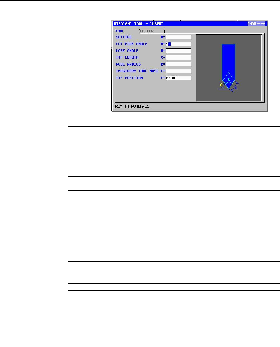
Tool definition block (straight tool): G1914
TOOL
Data item Meaning
Q SETTING Tool installation direction. Select the number of an
installation method from the illustration.
Remark) To be selected visually for both vertical
and horizontal lathes.
A CUT EDGE ANGLE Angle of the cutting edge (positive value)
B NOSE ANGLE Angle of the tool nose (positive value)
C TIP LENGTH Length of the tool nose portion that can actually cut
(positive value)
R NOSE RADIUS Radius of the tool nose (positive value)
E IMAGINARY TOOL NOSE Imaginary tool nose position. Select a number from
the menu indicated in the illustration.
Remark) To be selected visually for both vertical
and horizontal lathes.
F TIP POSITION [FRONT] : Display the tip in front of the holder. (tool
for forward spindle rotation)
[REAR] : Display the tip in the rear of the holder.
(tool for reverse spindle rotation)
HOLDER
Data item Meaning
L* HOLDER LENGTH Length of the holder (positive value)
W* HOLDER WIDTH Width of the holder (positive value)
I* HOLDER LENGTH 2 When the tip is installed in the direction opposite to
the holder installation direction, the distance
between the longitudinal end of the holder and tip
center (positive value)
J* HOLDER WIDTH 2 When the tip is installed in the direction opposite to
the holder installation direction, the distance
between the lateral end of the holder and tip center
(positive value)
Contents Summary of Manual Guide i Operators manual
- Page 1FANUC MANUAL GUIDE * OPERATOR’S MANUAL B-63874EN/05
- Page 2• No part of this manual may be reproduced in any form. • All specifications and designs are subject to change without notice. The export of this product is subject to the authorization of the government of the country from where the product is exported. In this manual we have tried as much as possi
- Page 3B-63874EN/05 SAFETY PRECAUTIONS SAFETY PRECAUTIONS When using a machine equipped with the FANUC MANUAL GUIDE i, be sure to observe the following safety precautions. s-1
- Page 4SAFETY PRECAUTIONS B-63874EN/05 1.1 DEFINITION OF WARNING, CAUTION, AND NOTE This manual includes safety precautions for protecting the user and preventing damage to the machine. Precautions are classified into Warning and Caution according to the degree of the risk or the severity of damage. Also,
- Page 5B-63874EN/05 SAFETY PRECAUTIONS 1.2 GENERAL WARNINGS AND CAUTIONS To ensure safety while using a machine featuring the MANUAL GUIDE i function, observe the following precautions: WARNING 1 Confirm, on the screen, that the data has been entered correctly before proceeding to the next operation. Attem
- Page 6
- Page 7B-63874EN/05 TABLE OF CONTENTS TABLE OF CONTENTS SAFETY PRECAUTIONS............................................................................s-1 I. GENERAL 1 OVERVIEW OF THIS MANUAL.............................................................. 3 2 READ AT FIRST ....................................
- Page 8TABLE OF CONTENTS B-63874EN/05 II. OPERATION 1 OVERVIEW OF THE PROCEDURE ..................................................... 43 1.1 MAIN FEATURES OF MANUAL GUIDE i ................................................... 44 2 MACHINING PROGRAM FORMAT ....................................................
- Page 9B-63874EN/05 TABLE OF CONTENTS 5 DETAILED DESCRIPTIONS ABOUT ENTERING ARBITRARY FIGURES............................................................................................... 84 5.1 INCREMENTAL PROGRAMMING .............................................................. 85 5.1.1 Arbitrary Figu
- Page 10TABLE OF CONTENTS B-63874EN/05 9.1.1 Program Selection Operation and Other Operations in Drawing during Machining.............................................................................................................164 9.1.2 Selecting Whether to Display the Tool Path or Not in Drawing during
- Page 11B-63874EN/05 TABLE OF CONTENTS 9.10.4 Simulation and Actual Working of the Machine..................................................219 10 SETTING DATA .................................................................................. 222 10.1 SETTING THE WORKPIECE COORDINATE DATA...................
- Page 12TABLE OF CONTENTS B-63874EN/05 13.5.5 Copying ................................................................................................................261 13.5.6 Initialization .........................................................................................................262 13.5.7
- Page 13B-63874EN/05 TABLE OF CONTENTS 15.25 SHORTCUTS FOR THE FREE FIGURE INPUT SCREEN ....................... 274 15.26 SHORTCUTS FOR THE FREE FIGURE CREATION SCREEN ............... 274 16 HELP SCREEN ................................................................................... 275 17 MEMORY CARD IN
- Page 14TABLE OF CONTENTS B-63874EN/05 21.5 DISPLAY OF ARBITRARY FIGURES OF M98 SUBPROGRAMS ............ 305 22 SCREEN HARD COPY ....................................................................... 306 23 DISPLAYING MACHINING TIME (FOR Series 16i/18i/21i ONLY) ... 307 23.1 FORMAT OF MACHINING TIME DATA .
- Page 15B-63874EN/05 TABLE OF CONTENTS 1.4 CONTOURING .......................................................................................... 382 1.4.1 Machining Type Blocks for Contouring ..............................................................382 1.4.2 Fixed Form Figure Blocks for Contouring (XY
- Page 16TABLE OF CONTENTS B-63874EN/05 2.2.1 Machining Type Blocks for Turning....................................................................488 2.2.2 Arbitrary Figure Blocks for Turning ....................................................................516 2.3 TURNING GROOVING........................
- Page 17B-63874EN/05 TABLE OF CONTENTS 2.4 HOW TO SELECT PATH .......................................................................... 596 2.5 OTHERS.................................................................................................... 596 3 PROCESS LIST EDITING FUNCTION ....................
- Page 18TABLE OF CONTENTS B-63874EN/05 1.2 SCREEN DISPLAY ITEMS........................................................................ 637 1.3 DISABLE WARNING MESSAGE............................................................... 638 2 VIEWING AND SETTING TOOL OFFSET VALUES .......................... 639 2
- Page 19B-63874EN/05 TABLE OF CONTENTS 6.2 DISPLAYED OFFSET TYPES (SET BY THE MACHINE TOOL BUILDER)............................................... 674 7 DISPLAY TOOL MANAGEMENT DATA OF CNC STANDARD SCREEN .......................................................................................................
- Page 20TABLE OF CONTENTS B-63874EN/05 2.5.7.1 Entering in ISO-code form directly.................................................................................................... 707 2.5.7.2 Entering by fixed form sentence menu .............................................................................
- Page 21B-63874EN/05 TABLE OF CONTENTS 3.6 CHECKING OF THE PART PROGRAM.................................................... 740 3.6.1 Checking by Animation........................................................................................740 APPENDIX A PARAMETERS........................................
- Page 22TABLE OF CONTENTS B-63874EN/05 A.4 PARAMETERS FOR TURNING CYCLE OPTIONS .................................. 795 A.4.1 Parameters Common to Turning Cycles...............................................................795 A.4.2 Parameters for Turning Cycle Machining ....................................
- Page 23I. GENERA
- Page 24
- Page 25B-63874EN/05 GENERAL 1.OVERVIEW OF THIS MANUAL 1 OVERVIEW OF THIS MANUAL This manual describes the functions of "MANUAL GUIDE i" for the Series 16i/18i/21i-MODEL B or Series 30i-MODEL A and the MANUAL GUIDE i simulator for the personal computer. For other functions, refer to the operator’s manual fo
- Page 262.READ AT FIRST GENERAL B-63874EN/05 2 READ AT FIRST In this chapter, you will find the explanation of the place where you should refer to when you operate MANUAL GUIDE i. When trying to use a machine equipped with the FANUC MANUAL GUIDE i, be sure to observe the safety precautions written in this m
- Page 27B-63874EN/05 GENERAL 2.READ AT FIRST How to install MANUAL GUIDE i to CNC In ordinary case, MANAUL GUIDE i is installed in an CNC and prepared by MTB such as parameter setting. In that case, you can use MANUAL GUIDE i as it is. However, by some reasons, there is a case such like you must install MAN
- Page 282.READ AT FIRST GENERAL B-63874EN/05 sentence function. Fixed form sentences, programming template, are made in advance and can be used by selecting from the menu during programming operations. In to details, refer to the following part. • Making and using of fixed form sentence II 3.14. FIXED FORM
- Page 29B-63874EN/05 GENERAL 2.READ AT FIRST How to modify part of cycle machining motions While cycle machining which can be used in MANUAL GUIDE i can create the actual machining motions automatically by using entered cycle data, modifying part of the created machining motions cannot be done. However, the
- Page 302.READ AT FIRST GENERAL B-63874EN/05 As for short cut key operation, refer to the following part. • Details of short cut key operation II 15 SHORTCUT KEY OPERATIONS • Displaying explanation of short cut key operation II 16 HELP SCREEN: Pressing HELP key on the MDI panel displays the window of HELP s
- Page 31B-63874EN/05 GENERAL 3.ALL-IN-ONE SCREEN 3 ALL-IN-ONE SCREEN In MANUAL GUIDE i, basically, only one screen called the All-in-one Screen is used for all the operations from trial machining to actual machining. Title area CNC status area MANUAL GUIDE i ACTUAL POS DIST TO GO SPINDLE Program Status indi
- Page 323.ALL-IN-ONE SCREEN GENERAL B-63874EN/05 • Actual speed and load meter (for the axis with the maximum load) Remark) It is possible to display Actual speed in Feed per revolution. ( Refer to the parameter No.14703#0. ) • Spindle rotating speed and spindle load meter • Program number and process numbe
- Page 33B-63874EN/05 GENERAL 3.ALL-IN-ONE SCREEN Remark) The soft keys described in this manual are specified to 12 keys placed under the screen, LCD, as shown in the following example. The meaning of each soft key is various by the displayed content on the screen, and will be displayed on the relevant part
- Page 344.SYMBOLS USED GENERAL B-63874EN/05 4 SYMBOLS USED In this manual, the following conventions are used for keys. (1) Function buttons are indicated in bold type: Example) PROGRM, OFSET (2) The numbers to be input by numerical keys are underlined. Example) 12.345 (3) The input key is indicated in bold
- Page 35B-63874EN/05 GENERAL 5.NOTES ON CREATING PROGRAMS 5 NOTES ON CREATING PROGRAMS The notes that should be observed when creating a program are described below. Read the notes before creating a program. 1. General notes on machining programs <1> Use ISO code form (G code commands) basically for a machi
- Page 365.NOTES ON CREATING PROGRAMS GENERAL B-63874EN/05 <7> By setting bit 3 of parameter No. 27000 to 1, a cylindrical interpolation command (G07.1) required for machining (cylindrical interpolation) on the ZC plane can be automatically specified during cycle machining. Upon completion of the cycle machi
- Page 37B-63874EN/05 GENERAL 5.NOTES ON CREATING PROGRAMS When the parameter No. 5103#2 is set to 1 : If an axis normal to or parallel with a specified plane is specified during a hole machining canned cycle, the specification is regarded as a positioning command. <7> With a CNC of the T series as well, ent
- Page 386.MANUAL GUIDE i SIMULATOR FOR THE PERSONAL COMPUTER GENERAL B-63874EN/05 6 MANUAL GUIDE i SIMULATOR FOR THE PERSONAL COMPUTER This chapter describes the MANUAL GUIDE i simulator for the personal computer. NOTE The specifications of the MANUAL GUIDE i simulator for the personal computer are subject
- Page 39B-63874EN/05 GENERAL 6.MANUAL GUIDE i SIMULATOR FOR THE PERSONAL COMPUTER 6.1 OPERATING ENVIRONMENT 6.1.1 Product Components • CD-ROM disk MANUAL GUIDE i simulator software for the personal computer • Hardware protection key 6.1.2 Operating Environment • Main computer unit - PC/AT-compatible machine
- Page 406.MANUAL GUIDE i SIMULATOR FOR THE PERSONAL COMPUTER GENERAL B-63874EN/05 6.2 METHOD OF INSTALLATION For installation, the administrator authority for the computer is required. Insert the CD-ROM of the MANUAL GUIDE i simulator for the personal computer into the CD-ROM drive. Execute "SetUp.exe" on t
- Page 41B-63874EN/05 GENERAL 6.MANUAL GUIDE i SIMULATOR FOR THE PERSONAL COMPUTER During installation, the system prompts you to agree upon the license agreement for using this software. If you agree, click [Yes]. If you select [No], a dialog box for checking if the installation may be stopped is displayed.
- Page 426.MANUAL GUIDE i SIMULATOR FOR THE PERSONAL COMPUTER GENERAL B-63874EN/05 In the dialog box for setup type selection, you can select full installation or custom installation. When full installation is selected, a free space of about 700 MB is required. For custom installation, the required free spac
- Page 43B-63874EN/05 GENERAL 6.MANUAL GUIDE i SIMULATOR FOR THE PERSONAL COMPUTER 6.3 SIMULATION CNC SELECTION Start the MANUAL GUIDE i simulator by choosing [Start] menu → [Programs] → [FANUC] → [ManualGuide i Simulator]. When the MANUAL GUIDE i simulator is started, a dialog box for selecting a simulator
- Page 446.MANUAL GUIDE i SIMULATOR FOR THE PERSONAL COMPUTER GENERAL B-63874EN/05 6.4 FULL-SCREEN DISPLAY When the MANUAL GUIDE i simulator is started, the simulator is displayed on the full screen of the personal computer. Main simulator screen Machine operation MDI button button With the MANUAL GUIDE i si
- Page 45B-63874EN/05 GENERAL 6.MANUAL GUIDE i SIMULATOR FOR THE PERSONAL COMPUTER 6.5 PARAMETER 1 Parameters created with the FS16i/18i/21i cannot be input. 2 When using a parameter of the FS16i/18i/21i, convert the parameter to the FS30i format. 3 Parameters in the FS30i format can be used without modifica
- Page 466.MANUAL GUIDE i SIMULATOR FOR THE PERSONAL COMPUTER GENERAL B-63874EN/05 6.7 NOTES 1 The operation and functions listed below described in the operator's manual cannot be used with the MANUAL GUIDE i simulator for the personal computer. - Operation in the MDI mode - Operation in a manual mode (hand
- Page 47B-63874EN/05 GENERAL 6.MANUAL GUIDE i SIMULATOR FOR THE PERSONAL COMPUTER 6.8 SIMULATOR DEFINITION FILE FORMAT The simulator definition file is a text file where information such as CNC model and display unit size information is written in a specified format. The ini file format of Windows is used.
- Page 486.MANUAL GUIDE i SIMULATOR FOR THE PERSONAL COMPUTER GENERAL B-63874EN/05 6.8.3.1 [Simulator_MachineSetting_MaxNumber] section Key name : maxnumber Outline : Code a maximum subscript value for the simulator definitions to be found in the file. Character string to be set : Maximum subscript number to
- Page 49B-63874EN/05 GENERAL 6.MANUAL GUIDE i SIMULATOR FOR THE PERSONAL COMPUTER Key name : from_dat_filepath Outline : Code the relative path of From.dat corresponding to a selected simulator definition. Character string to be set : Relative path of From.dat Explanation : Specify the relative path of From
- Page 506.MANUAL GUIDE i SIMULATOR FOR THE PERSONAL COMPUTER GENERAL B-63874EN/05 Key name : userdef_folderpath1 Outline : Code the relative path of the user definition file of a selected simulator definition. Character string to be set : Relative path of a user definition file Explanation : Code the relati
- Page 51B-63874EN/05 GENERAL 6.MANUAL GUIDE i SIMULATOR FOR THE PERSONAL COMPUTER 6.9 DISPLAY DATA ini FILE FORMAT The display data ini file is a text file where information about images and buttons to be arranged on the screen is specified. The ini file format of Windows is used. 6.9.1 Comment A comment ca
- Page 526.MANUAL GUIDE i SIMULATOR FOR THE PERSONAL COMPUTER GENERAL B-63874EN/05 6.9.3 Key The keys are described on a section-by-section basis. 6.9.3.1 [settings] section Key name : bgcolor Outline : Specify a background color. Setting method : bgcolor = r, g, b Specify a number from 0 to 255 in r, g, and
- Page 53B-63874EN/05 GENERAL 6.MANUAL GUIDE i SIMULATOR FOR THE PERSONAL COMPUTER 6.9.3.2 [frame_mainscreen] section Key name : image Outline : Specify the path of an image to be displayed in the CNC display section area of the MGi manager. Setting method : image = drive:¥dir1…¥filename Example: image=.¥ima
- Page 546.MANUAL GUIDE i SIMULATOR FOR THE PERSONAL COMPUTER GENERAL B-63874EN/05 6.9.3.3 [cnctitle] section Key name : image Outline : Specify the path of a title image to be displayed within the main frame. Setting method : image = drive:¥dir1…¥filename Example: image=.¥image¥titleFS30i.bmp Details : Spec
- Page 55B-63874EN/05 GENERAL 6.MANUAL GUIDE i SIMULATOR FOR THE PERSONAL COMPUTER 6.9.3.4 [softkey] section Key name : keynum Outline : Specify the number of buttons that are displayed in the main frame and operate as soft keys. Setting method : keynum = n Example: When 12 soft keys are used keynum=12 Detai
- Page 566.MANUAL GUIDE i SIMULATOR FOR THE PERSONAL COMPUTER GENERAL B-63874EN/05 6.9.3.5 [frame_mdikey] section Key name : image Outline : Specify the path of an image to be displayed as a frame for MDI key display. Setting method : image = drive:¥dir1…¥filename Example: image=.¥image¥frameQWERTY.bmp Detai
- Page 57B-63874EN/05 GENERAL 6.MANUAL GUIDE i SIMULATOR FOR THE PERSONAL COMPUTER 6.9.3.6 [mdikey] section Key name : keynum Outline : Specify the number of buttons that are displayed in a frame for MDI key display and operate as MDI keys. Setting method : keynum = n Example: When 66 MDI keys are used keynu
- Page 586.MANUAL GUIDE i SIMULATOR FOR THE PERSONAL COMPUTER GENERAL B-63874EN/05 6.9.3.7 [frame_functionkey] section Key name : image Outline : Specify the path of an image to be displayed as a frame for function key display. Setting method : image = drive:¥dir1…¥filename Example: image=.¥image¥frameFunc.b
- Page 59B-63874EN/05 GENERAL 6.MANUAL GUIDE i SIMULATOR FOR THE PERSONAL COMPUTER 6.9.3.8 [functionkey] section Key name : keynum Outline : Specify the number of buttons that are displayed in a frame for function key display and operate as function keys. Setting method : keynum = n Example: When two functio
- Page 606.MANUAL GUIDE i SIMULATOR FOR THE PERSONAL COMPUTER GENERAL B-63874EN/05 6.9.3.9 Information to be passed when a button is pressed When specifying buttons such as soft keys, MDI keys, and function keys in a display data ini file, specify key information to be passed to the CNC display section appli
- Page 61B-63874EN/05 GENERAL 6.MANUAL GUIDE i SIMULATOR FOR THE PERSONAL COMPUTER CNC key Corresponding CNC key Corresponding character string character string A a 1 1 B b 2 2 C c 3 3 D d 4 4 E e 5 5 F f 6 6 G g 7 7 H h 8 8 I i 9 9 J j 0 0 K k - - L l . . M m / / N n ( {(} O o ) {)} P p ? ? Q q , COMMA R r
- Page 626.MANUAL GUIDE i SIMULATOR FOR THE PERSONAL COMPUTER GENERAL B-63874EN/05 CNC key Corresponding CNC key Corresponding character string character string RESET @ SOFTKEY 1 Q HELP {‘} SOFTKEY 2 A SHIFT SHIFT SOFTKEY 3 Z ALTER ` SOFTKEY 4 X INSERT ^n SOFTKEY 5 C DELETE DEL SOFTKEY 6 V INPUT {ENTER} SOFT
- Page 63II. OPERATIO
- Page 64
- Page 65B-63874EN/05 OPERATION 1.OVERVIEW OF THE PROCEDURE 1 OVERVIEW OF THE PROCEDURE - 43 -
- Page 661.OVERVIEW OF THE PROCEDURE OPERATION B-63874EN/05 1.1 MAIN FEATURES OF MANUAL GUIDE i By using MANUAL GUIDE i, the operator can carry out routine machining easily. 1) Integrated operation screen that enables almost all routine machining operations A single integrated operation screen enables routin
- Page 67B-63874EN/05 OPERATION 1.OVERVIEW OF THE PROCEDURE 8) Realistic animated simulation (option) Machining programs can be checked easily, using an animated simulation method that can realistically show what the surface machined with a specific type of tool tip is like. In addition, you can check a simu
- Page 682.MACHINING PROGRAM FORMAT OPERATION B-63874EN/05 2 MACHINING PROGRAM FORMAT Machining programs used with MANUAL GUIDE i are created using the ISO code format, which is widely used in CNC machine tools. They use 4-digit G code machining and measurement cycles to implement further advanced machining
- Page 69B-63874EN/05 OPERATION 2.MACHINING PROGRAM FORMAT Remark) In the screen, in which numerical data are directly entered such as offset data or cycle machining data, the cursor is specified by displaying the data frame by blue. The part specified by blue frame is called “data item selected by the curso
- Page 703.EDITING MACHINING PROGRAMS OPERATION B-63874EN/05 3 EDITING MACHINING PROGRAMS - 48 -
- Page 71B-63874EN/05 OPERATION 3.EDITING MACHINING PROGRAMS 3.1 MACHINING PROGRAM WINDOW AND EIDITNG MANUAL GUIDE i uses a program window to input and edit machining programs (in ISO code format). The program window is operated using the following soft keys, which are displayed by pressing the leftmost soft
- Page 723.EDITING MACHINING PROGRAMS OPERATION B-63874EN/05 The program is edited using the following soft keys, which are displayed by pressing the leftmost soft key [<] or rightmost soft key [>] several times. NEWPRG OPEN SRCH↑ SRCH↓ O SRCH COPY CUT DELETE KEYPST PASTE Remark) Basically, soft keys are pla
- Page 73B-63874EN/05 OPERATION 3.EDITING MACHINING PROGRAMS 3.2 CREATING MACHINING PROGRAMS NEWPRG O LIST SRCH↑ SRCH↓ O SRCH COPY CUT DELETE KEYPST PASTE Pressing [NEWPRG] displays the program creation window. For the program creation window, the following soft keys are displayed. CREATE CANCEL In this wind
- Page 743.EDITING MACHINING PROGRAMS OPERATION B-63874EN/05 3.3 EDITING IN A PROGRAM LIST NEWPRG O LIST SRCH↑ SRCH↓ O SRCH COPY CUT DELETE KEYPST PASTE Pressing [O LIST] displays a window that lists registered machining programs. By pressing the ← or → cursor key, a sort type (sort by number, sort by date a
- Page 75B-63874EN/05 OPERATION 3.EDITING MACHINING PROGRAMS [SEARCH] : This soft key displays the program search window. After entering a desired program number in the window, using numeric keys, press [SEARCH]. [M CARD] : This soft key enables input/output to and from the memory card. [ALLDEL] : This soft
- Page 763.EDITING MACHINING PROGRAMS OPERATION B-63874EN/05 3.4 SEARCHING FOR A MACHINING PROGRAM TO BE EDITED NEWPRG O LIST SRCH↑ SRCH↓ O SRCH COPY CUT DELETE KEYPST PASTE After entering a desired program number, using numeric keys, pressing [O SRCH] can select the program. Pressing [O SRCH] without enteri
- Page 77B-63874EN/05 OPERATION 3.EDITING MACHINING PROGRAMS 3.5 BASIC EDITING OPERATIONS OF PART PROGRAM Since MANUAL GUIDE i uses ISO-code form part program, editing of 1 word, minimum unit of the program and made from address and numerical data, are available by using INSERT, ALTER and DELETE keys, which
- Page 783.EDITING MACHINING PROGRAMS OPERATION B-63874EN/05 3.5.4 Deleting a Word (DELETE key) Operation (1) Select the word to be deleted by placing the cursor on the word. (2) Press DELETE. NOTE 1 As the deleting operation in the CNC program screen, no prompting message for deleting a word is displayed. 2
- Page 79B-63874EN/05 OPERATION 3.EDITING MACHINING PROGRAMS 3.6 SEARCH (FORWARD AND BACKWARD) NEWPRG O LIST SRCH↑ SRCH↓ O SRCH COPY CUT DELETE KEYPST PASTE [ ] After a character string is entered using MDI keys, pressing [SRCH↑] (backward search) or [SRCH↓] (forward search) searches for the specified charac
- Page 803.EDITING MACHINING PROGRAMS OPERATION B-63874EN/05 3.7 CUT NEWPRG O LIST SRCH↑ SRCH↓ O SRCH COPY CUT DELETE KEYPST PASTE Pressing [CUT] displays a message that prompts you to select a range of data to be cut. First select the cut range (by displaying it in yellow), using cursor keys, and then press
- Page 81B-63874EN/05 OPERATION 3.EDITING MACHINING PROGRAMS 3.9 PASTE NEWPRG O LIST SRCH↑ SRCH↓ O SRCH COPY CUT DELETE KEYPST PASTE Pressing [PASTE] pastes the contents of the clipboard to the place that immediately follows the current cursor position. The clipboard contents are preserved. 3.10 DELETE NEWPR
- Page 823.EDITING MACHINING PROGRAMS OPERATION B-63874EN/05 3.11 KEY-IN PASTE NEWPRG O LIST SRCH↑ SRCH↓ O SRCH COPY CUT DELETE KEYPST PASTE Pressing [KEYPST] copies the contents of a range selected (displayed in yellow) using the cursor to the key-in buffer. Using the ← and → cursor keys can move the cursor
- Page 83B-63874EN/05 OPERATION 3.EDITING MACHINING PROGRAMS 3.12 UNDO, REDO G-CONT UNDO REDO WK-SET T-OFS SETING Pressing [REDO] during editing in the MDI mode, EDIT mode, or MEM mode can cancel (undo) a program editing operation using the MANUAL GUIDE i. Pressing [UNDO] can cancel (redo) the cancellation o
- Page 843.EDITING MACHINING PROGRAMS OPERATION B-63874EN/05 3.13 M-CODE MENU Pressing the leftmost soft key [<] or rightmost soft key [>] several times displays [M CODE] as follows: START CYCLE END MECYC ALTER FIGURE M CODE FIXFRM Pressing [M CODE] displays the M code menu. The following soft keys are displ
- Page 85B-63874EN/05 OPERATION 3.EDITING MACHINING PROGRAMS 4) Pressing [ALTER], then M-code will be replaced to the newly selected one. NOTE 1 In many cases, M codes in the M code menu are set up to a machine tool by the machine tool builder. So, the M code menu varies from one machine tool to another. 2 I
- Page 863.EDITING MACHINING PROGRAMS OPERATION B-63874EN/05 3.14 FIXED FORM SENTENCE INSERTION Pressing the leftmost soft key [<] or rightmost soft key [>] several times displays [FIXFRM] for milling or turning. However, there is a case that either of them is displayed depending on the machine construction,
- Page 87B-63874EN/05 OPERATION 3.EDITING MACHINING PROGRAMS Select a fixed form sentence group, using the ← and → cursor keys, and then select a fixed form sentence from the fixed form sentence group, using the ↑ and ↓ cursor keys. Pressing [INSERT] inserts the selected fixed form sentence to the place that
- Page 884.EDITING CYCLE MACHINING OPERATIONS OPERATION B-63874EN/05 4 EDITING CYCLE MACHINING OPERATIONS Pressing the leftmost soft key [<] or rightmost soft key [>] several times displays the following cycle machining soft key menu. Two cycle machining types, milling and turning, are optionally supported.
- Page 89B-63874EN/05 OPERATION 4.EDITING CYCLE MACHINING OPERATIONS 4.1 ENTERING THE START COMMAND START CYCLE END MESCYC ALTER FIGURE M CODE FIXFRM Pressing [START] displays the start command fixed form sentence menu. (Example of the fixed form sentence menu for milling start) (Example of the fixed form se
- Page 904.EDITING CYCLE MACHINING OPERATIONS OPERATION B-63874EN/05 NOTE In many cases, fixed form sentences in the fixed form sentence menu are set up to a machine tool by the machine tool builder. So, the fixed form sentence menu varies from one machine tool to another. Operators can make changes and addi
- Page 91B-63874EN/05 OPERATION 4.EDITING CYCLE MACHINING OPERATIONS 4.2 SELECTING A CYCLE MACHINING TYPE START CYCLE END MESCYC ALTER FIGURE M CODE FIXFRM Pressing [CYCLE] displays the cycle machining menu. The following soft keys are displayed for the cycle machining menu. SELECT CANCEL Select a cycle mach
- Page 924.EDITING CYCLE MACHINING OPERATIONS OPERATION B-63874EN/05 NOTE The scroll bar displayed on the right edge of the cycle machining menu window indicates the approximate position of the cursor throughout the cycle machining menu. If the scroll bar marker is on the middle of the scroll bar, therefore,
- Page 93B-63874EN/05 OPERATION 4.EDITING CYCLE MACHINING OPERATIONS 4.3 ENTERING CYCLE MACHINING DATA The cycle machining data entry window is divided into two sections, one section for cutting conditions and the other for detailed data. CUT COND. DETAIL Pressing the ← or → cursor key switches between the t
- Page 944.EDITING CYCLE MACHINING OPERATIONS OPERATION B-63874EN/05 NOTE 1 Among the data item displayed in the cutting condition window, there are data should be danger if they are set automatically such as cutting amount or feedrate. These data should be entered by an operator always. Other data are set a
- Page 95B-63874EN/05 OPERATION 4.EDITING CYCLE MACHINING OPERATIONS 4.4 SELECTING FIGURES In usual case, entering a cycle motion block displays continuously the following figure menu exclusively used for the already entered cycle machining. (Example of figure menu for pocketing) The cycle figure menu window
- Page 964.EDITING CYCLE MACHINING OPERATIONS OPERATION B-63874EN/05 Pressing the → cursor key displays the menu window of subprogram and the character in the selected tab is displayed in blue. If some figure blocks were created as subprogram in advance, the subprogram number and name are displayed in the su
- Page 97B-63874EN/05 OPERATION 4.EDITING CYCLE MACHINING OPERATIONS 4.5 ENTERING FIXED FORM FIGURE DATA FOR CYCLE MACHINING Selecting the fixed form figure displays the data entry window for cycle machining fixed form data entry window. (Example of the pocketing fixed form figure) A data entry window for ho
- Page 984.EDITING CYCLE MACHINING OPERATIONS OPERATION B-63874EN/05 NOTE 1 More than one figure can be entered in succession for a single cycle machining type. Cycle machining is executed for each of the specified figures sequentially. 2 An ordinary ISO code block can be entered between cycle machining and
- Page 99B-63874EN/05 OPERATION 4.EDITING CYCLE MACHINING OPERATIONS <2> A screen for selecting fixed form figure data as a subprogram is displayed as shown below. <3> When creating fixed form figure data as a subprogram, select "CREATE AS SUB PROGRAM". <4> If a comment is entered, the entered comment is add
- Page 1004.EDITING CYCLE MACHINING OPERATIONS OPERATION B-63874EN/05 4.6 ENTERING ARBITRARY FIGURE DATA FOR CYCLE MACHINING For cycle machining, an arbitrary figure consisting of circles and straight lines can be entered by performing automatic calculation on entered data to obtain the end point of each figu
- Page 101B-63874EN/05 OPERATION 4.EDITING CYCLE MACHINING OPERATIONS NOTE As figures are entered, they are drawn in the figure entry window. In the upper section of the window, symbols for entered figures are displayed sequentially, starting at the left. The ← or → cursor key can be used to select an entered
- Page 1024.EDITING CYCLE MACHINING OPERATIONS OPERATION B-63874EN/05 Select whichever creation method you want, using the ↑ and ↓ cursor keys. To write to the machining program that has been selected, simply press [OK]. To create a subprogram, enter a new subprogram number to the subprogram number item, and
- Page 103B-63874EN/05 OPERATION 4.EDITING CYCLE MACHINING OPERATIONS 4.7 ENTERING CONTOUR PROGRAMS It is possible to enter arbitrary figures consisting of circles and straight lines (contour programs), which are different from cycle machining. Pressing [G-CONT] displays the same window as for the arbitrary f
- Page 1044.EDITING CYCLE MACHINING OPERATIONS OPERATION B-63874EN/05 For editing figure blocks, entered figure data is written as a comment to each figure block. There is a start point G code (G1200, G1300, G1450, G1500, or G1600) in the first figure block in contour programming. Place the cursor on the bloc
- Page 105B-63874EN/05 OPERATION 4.EDITING CYCLE MACHINING OPERATIONS 4.8 ENTERING THE END COMMAND START CYCLE END MESCYC ALTER FIGURE M CODE FIXFRM Pressing [END] displays the end command fixed form sentence menu. Select a fixed form sentence, using the ↑ and ↓ cursor keys. Pressing [INSERT] inserts the sele
- Page 1065.DETAILED DESCRIPTIONS ABOUT ENTERING ARBITRARY FIGURES OPERATION B-63874EN/05 5 DETAILED DESCRIPTIONS ABOUT ENTERING ARBITRARY FIGURES This chapter explains data for arbitrary figures entered with MANUAL GUIDE i. NOTE 1 When entering arbitrary figures, enter all the data for each figure specified
- Page 107B-63874EN/05 OPERATION 5.DETAILED DESCRIPTIONS ABOUT ENTERING ARBITRARY FIGURES 5.1 INCREMENTAL PROGRAMMING In entering arbitrary figures of element “LINE” or “ARC”, the end point can be set as an incremental programming. When positioning the cursor on “END POINT”, the soft key [ST.P+I] and [ST.P-I]
- Page 1085.DETAILED DESCRIPTIONS ABOUT ENTERING ARBITRARY FIGURES OPERATION B-63874EN/05 NOTE 1 If the last figure element is “CORNER R” or “CHAMFER”, The point to set as the start point in this function is as follows. Start Point Start Point C R Fig1 Last figure is a chamfer. Fig2 Last figure is a corner R.
- Page 109B-63874EN/05 OPERATION 5.DETAILED DESCRIPTIONS ABOUT ENTERING ARBITRARY FIGURES Start point: G1200 (XY plane) ELEMENT (INPUT DATA) (Note 1) Data item Meaning T FIGURE ATTRIBUTE [FACE] : Used as a figure in facing (Note 2) [CONVEX] : Used as an outer-perimeter figure in contouring [CONCAV] : Used as
- Page 1105.DETAILED DESCRIPTIONS ABOUT ENTERING ARBITRARY FIGURES OPERATION B-63874EN/05 ELEMENT (OUTPUT DATA) (Note 3) Data item Meaning T FIGURE ATTRIBUTE [1] : Used as a figure in facing [2] : Used as an outer-perimeter figure in contouring [3] : Used as an inner-perimeter figure in contouring and emboss
- Page 111B-63874EN/05 OPERATION 5.DETAILED DESCRIPTIONS ABOUT ENTERING ARBITRARY FIGURES Straight line: G1201 (XY plane) ELEMENT (INPUT DATA) (Note 1) Data item Meaning D LINE DIRECTION The direction of a straight line is selected from a menu indicated on a soft key. X* END POINT X X coordinate of the end po
- Page 1125.DETAILED DESCRIPTIONS ABOUT ENTERING ARBITRARY FIGURES OPERATION B-63874EN/05 NOTE 1 ‘INPUT DATA’ means the items, which are displayed on the input data window in editing or altering. ELEMENT & ATTRIBUTE (OUTPUT DATA) (Note 2) Data item Meaning H END POINT X X coordinate of the end point of a stra
- Page 113B-63874EN/05 OPERATION 5.DETAILED DESCRIPTIONS ABOUT ENTERING ARBITRARY FIGURES Arc (CW): G1202 (XY plane) Arc (CCW): G1203 (XY plane) ELEMENT (INPUT DATA) (Note 1) Data item Meaning X* END POINT X X coordinate of an arc end point Remarks) Incremental programming is possible. Y* END POINT Y Y coordi
- Page 1145.DETAILED DESCRIPTIONS ABOUT ENTERING ARBITRARY FIGURES OPERATION B-63874EN/05 ELEMENT & ATTRIBUTE (OUTPUT DATA) (Note 2) Data item Meaning H END POINT X X coordinate of an arc end point (calculation result) V END PINT Y Y coordinate of an arc end point (calculation result) R RADIUS Arc radius (cal
- Page 115B-63874EN/05 OPERATION 5.DETAILED DESCRIPTIONS ABOUT ENTERING ARBITRARY FIGURES Chamfering: G1204 (XY plane) ELEMENT (INPUT DATA) (Note 1) Data item Meaning C CHAMFER Amount of chamfering (radius value, positive value) ATTRIBUTE (INPUT DATA) (Note 1) Data item Meaning T ELEMENT TYPE [PART] : Cut as
- Page 1165.DETAILED DESCRIPTIONS ABOUT ENTERING ARBITRARY FIGURES OPERATION B-63874EN/05 NOTE 2 By setting the parameter No.14851#0=1, Corner element between a blank element and a part element can be created in the opposite direction. C C C C C C Dotted line : blank element Normal line : part element - 94 -
- Page 117B-63874EN/05 OPERATION 5.DETAILED DESCRIPTIONS ABOUT ENTERING ARBITRARY FIGURES Corner rounding: G1205 (XY plane) ELEMENT (INPUT DATA) (Note 1) Data item Meaning R CORNER RADIUS Corner rounding (radius value, positive value) ATTRIBUTE (INPUT DATA) (Note 1) Data item Meaning T ELEMENT TYPE [PART] : C
- Page 1185.DETAILED DESCRIPTIONS ABOUT ENTERING ARBITRARY FIGURES OPERATION B-63874EN/05 NOTE 2 ‘OUTPUT DATA’ means the items, which are displayed on the program window as creating program. It can be referenced only for program display purposes. 3 By setting the parameter No.14851#0=1, Corner element between
- Page 119B-63874EN/05 OPERATION 5.DETAILED DESCRIPTIONS ABOUT ENTERING ARBITRARY FIGURES 5.2 ARBITRARY FIGURES FOR THE YZ PLANE Arbitrary figures in the YZ plane can be used in the following types of milling. 1. Facing 2. Contouring (Side cutting) 3. Pocketing 4. Grooving 5. Emboss machining NOTE See Chapter
- Page 1205.DETAILED DESCRIPTIONS ABOUT ENTERING ARBITRARY FIGURES OPERATION B-63874EN/05 ELEMENT (INPUT DATA) (Note 1) Data item Meaning P FIGURE ATTRIBUTE [RIGHT] : The right side of an entered figure as cutting [LEFT] : The left side of an entered figure as cutting Remarks) This item is displayed in Open f
- Page 121B-63874EN/05 OPERATION 5.DETAILED DESCRIPTIONS ABOUT ENTERING ARBITRARY FIGURES Straight line: G1301 (YZ plane) ELEMENT (INPUT DATA) (Note 1) Data item Meaning D LINE DIRECTION The direction of a straight line is selected from a menu indicated on a soft key. Y* END POINT Y Y coordinate of the end po
- Page 1225.DETAILED DESCRIPTIONS ABOUT ENTERING ARBITRARY FIGURES OPERATION B-63874EN/05 NOTE 1 ‘INPUT DATA’ means the items, which are displayed on the input data window in editing or altering. ELEMENT & ATTRIBUTE (OUTPUT DATA) (Note 2) Data item Meaning H END POINT Y Y coordinate of the end point of a stra
- Page 123B-63874EN/05 OPERATION 5.DETAILED DESCRIPTIONS ABOUT ENTERING ARBITRARY FIGURES Arc (CW): G1302 (YZ plane) Arc (CCW): G1303 (YZ plane) ELEMENT (INPUT DATA) (Note 1) Data item Meaning Y* END POINT Y Y coordinate of an arc end point Remarks) Incremental programming is possible. Z* END POINT Z Z coordi
- Page 1245.DETAILED DESCRIPTIONS ABOUT ENTERING ARBITRARY FIGURES OPERATION B-63874EN/05 ELEMENT & ATTRIBUTE (OUTPUT DATA) (Note 2) Data item Meaning H END POINT Y Y coordinate of an arc end point (calculation result) V END POINT Z Z coordinate of an arc end point (calculation result) R RADIUS Arc radius (ca
- Page 125B-63874EN/05 OPERATION 5.DETAILED DESCRIPTIONS ABOUT ENTERING ARBITRARY FIGURES Chamfering: G1304 (YZ plane) ELEMENT (INPUT DATA) (Note 1) Data item Meaning C CHAMFER Amount of chamfering (radius value, positive value) ATTRIBUTE (INPUT DATA) (Note 1) Data item Meaning T ELEMENT TYPE [PART] : Cut as
- Page 1265.DETAILED DESCRIPTIONS ABOUT ENTERING ARBITRARY FIGURES OPERATION B-63874EN/05 NOTE 3 By setting the parameter No.14851#0=1, Corner element between a blank element and a part element can be created in the opposite direction. C C C C C C Dotted line : blank element Normal line : part element - 104 -
- Page 127B-63874EN/05 OPERATION 5.DETAILED DESCRIPTIONS ABOUT ENTERING ARBITRARY FIGURES Corner rounding: G1305 (YZ plane) ELEMENT (INPUT DATA) (Note 1) Data item Meaning R CORNER RADIUS Corner rounding (radius value, positive value) ATTRIBUTE (INPUT DATA) (Note 1) Data item Meaning T ELEMENT TYPE [PART] : C
- Page 1285.DETAILED DESCRIPTIONS ABOUT ENTERING ARBITRARY FIGURES OPERATION B-63874EN/05 NOTE 2 ‘OUTPUT DATA’ means the items, which are displayed on the program window as creating program. It can be referenced only for program display purposes. 3 By setting the parameter No.14851#0=1, Corner element between
- Page 129B-63874EN/05 OPERATION 5.DETAILED DESCRIPTIONS ABOUT ENTERING ARBITRARY FIGURES 5.3 ARBITRARY FIGURES FOR THE POLAR COORDINATE INTERPOLATION PLANE (XC PLANE) The following types of milling can be specified also for the polar coordinate interpolation plane (XC plane), and arbitrary figures in the XC
- Page 1305.DETAILED DESCRIPTIONS ABOUT ENTERING ARBITRARY FIGURES OPERATION B-63874EN/05 ELEMENT (INPUT DATA) (Note 1) Data item Meaning W GROOVE WIDTH Groove width (Positive value) Remarks) This item is displayed in Grooving. P FIGURE ATTRIBUTE [RIGHT] : The right side of an entered figure as cutting [LEFT]
- Page 131B-63874EN/05 OPERATION 5.DETAILED DESCRIPTIONS ABOUT ENTERING ARBITRARY FIGURES ELEMENT (OUTPUT DATA) (Note 3) Data item Meaning Y ROTATION AXIS [1] : The rotation axis is the C axis. NAME [2] : The rotation axis is the A axis (No.27000#1=1) [3] : The rotation axis is the B axis (No.27000#2=1) [4] :
- Page 1325.DETAILED DESCRIPTIONS ABOUT ENTERING ARBITRARY FIGURES OPERATION B-63874EN/05 Straight line: G1501 (XC plane) ELEMENT (INPUT DATA) (Note 1) Data item Meaning D LINE DIRECTION The direction of a straight line is selected from a menu indicated on a soft key. X* END POINT X X coordinate of the end po
- Page 133B-63874EN/05 OPERATION 5.DETAILED DESCRIPTIONS ABOUT ENTERING ARBITRARY FIGURES NOTE 1 ‘INPUT DATA’ means the items, which are displayed on the input data window in editing or altering. ELEMENT & ATTRIBUTE (OUTPUT DATA) (Note 2) Data item Meaning H END POINT X X coordinate of the end point of a stra
- Page 1345.DETAILED DESCRIPTIONS ABOUT ENTERING ARBITRARY FIGURES OPERATION B-63874EN/05 Arc (CW): G1502 (XC plane) Arc (CCW): G1503 (XC plane) ELEMENT (INPUT DATA) (Note 1) Data item Meaning X* END POINT X X coordinate of an arc end point Remarks) Incremental programming is possible. C* END POINT C C coordi
- Page 135B-63874EN/05 OPERATION 5.DETAILED DESCRIPTIONS ABOUT ENTERING ARBITRARY FIGURES ELEMENT & ATTRIBUTE (OUTPUT DATA) (Note 2) Data item Meaning H END POINT X X coordinate of an arc end point (calculation result) V END POINT C C coordinate of an arc end point (calculation result) R RADIUS Arc radius (ca
- Page 1365.DETAILED DESCRIPTIONS ABOUT ENTERING ARBITRARY FIGURES OPERATION B-63874EN/05 Chamfering: G1504 (XC plane) ELEMENT (INPUT DATA) (Note 1) Data item Meaning C CHAMFER Amount of chamfering (radius value, positive value) ATTRIBUTE (INPUT DATA) (Note 1) Data item Meaning T ELEMENT TYPE [PART] : Cut as
- Page 137B-63874EN/05 OPERATION 5.DETAILED DESCRIPTIONS ABOUT ENTERING ARBITRARY FIGURES NOTE 3 By setting the parameter No.14851#0=1, Corner element between a blank element and a part element can be created in the opposite direction. C C C C C C Dotted line : blank element Normal line : part element - 115 -
- Page 1385.DETAILED DESCRIPTIONS ABOUT ENTERING ARBITRARY FIGURES OPERATION B-63874EN/05 Corner rounding: G1505 (XC plane) ELEMENT (INPUT DATA) (Note 1) Data item Meaning R CORNER RADIUS Corner rounding (radius value, positive value) ATTRIBUTE (INPUT DATA) (Note 1) Data item Meaning T ELEMENT TYPE [PART] : C
- Page 139B-63874EN/05 OPERATION 5.DETAILED DESCRIPTIONS ABOUT ENTERING ARBITRARY FIGURES NOTE 2 ‘OUTPUT DATA’ means the items, which are displayed on the program window as creating program. It can be referenced only for program display purposes. 3 By setting the parameter No.14851#0=1, Corner element between
- Page 1405.DETAILED DESCRIPTIONS ABOUT ENTERING ARBITRARY FIGURES OPERATION B-63874EN/05 5.4 ARBITRARY FIGURES FOR THE CYLINDRICAL SURFACE (ZC PLANE) The following types of milling can be specified also for the cylindrical surface (ZC plane), and arbitrary figures in the ZC plane can be used in these milling
- Page 141B-63874EN/05 OPERATION 5.DETAILED DESCRIPTIONS ABOUT ENTERING ARBITRARY FIGURES ELEMENT (INPUT DATA) (Note 1) Data item Meaning D HEIGHT/DEPTH Height or Depth from Base position to cutting surface Remarks) This item is displayed in Contouring, Pocketing, Grooving and Emboss machining. W GROOVE WIDTH
- Page 1425.DETAILED DESCRIPTIONS ABOUT ENTERING ARBITRARY FIGURES OPERATION B-63874EN/05 ELEMENT (OUTPUT DATA) (Note 3) Data item Meaning P FIGURE ATTRIBUTE [1] : The right side of an entered figure as cutting [2] : The left side of an entered figure as cutting Remarks) This item is displayed in Open figure
- Page 143B-63874EN/05 OPERATION 5.DETAILED DESCRIPTIONS ABOUT ENTERING ARBITRARY FIGURES Straight line: G1601 (ZC plane) ELEMENT (INPUT DATA) (Note 1) Data item Meaning D LINE DIRECTION The direction of a straight line is selected from a menu indicated on a soft key. Z* END POINT Z Z coordinate of the end po
- Page 1445.DETAILED DESCRIPTIONS ABOUT ENTERING ARBITRARY FIGURES OPERATION B-63874EN/05 NOTE 1 ‘INPUT DATA’ means the items, which are displayed on the input data window in editing or altering. ELEMENT & ATTRIBUTE (OUTPUT DATA) (Note 2) Data item Meaning H END POINT Z Z coordinate of the end point of a stra
- Page 145B-63874EN/05 OPERATION 5.DETAILED DESCRIPTIONS ABOUT ENTERING ARBITRARY FIGURES Arc (CW): G1602 (ZC plane) Arc (CCW): G1603 (ZC plane) ELEMENT (INPUT DATA) (Note 1) Data item Meaning Z* END POINT Z Z coordinate of an arc end point Remarks) Incremental programming is possible. C* END POINT C C coordi
- Page 1465.DETAILED DESCRIPTIONS ABOUT ENTERING ARBITRARY FIGURES OPERATION B-63874EN/05 ELEMENT & ATTRIBUTE (OUTPUT DATA) (Note 2) Data item Meaning H END POINT Z Z coordinate of an arc end point (calculation result) V END POINT C C coordinate of an arc end point (calculation result) R RADIUS Arc radius (ca
- Page 147B-63874EN/05 OPERATION 5.DETAILED DESCRIPTIONS ABOUT ENTERING ARBITRARY FIGURES Chamfering: G1604 (ZC plane) ELEMENT (INPUT DATA) (Note 1) Data item Meaning C CHAMFER Amount of chamfering (radius value, positive value) ATTRIBUTE (INPUT DATA) (Note 1) Data item Meaning T ELEMENT TYPE [PART] : Cut as
- Page 1485.DETAILED DESCRIPTIONS ABOUT ENTERING ARBITRARY FIGURES OPERATION B-63874EN/05 NOTE 3 By setting the parameter No.14851#0=1, Corner element between a blank element and a part element can be created in the opposite direction. C C C C C C Dotted line : blank element Normal line : part element - 126 -
- Page 149B-63874EN/05 OPERATION 5.DETAILED DESCRIPTIONS ABOUT ENTERING ARBITRARY FIGURES Corner rounding: G1605 (ZC plane) ELEMENT (INPUT DATA) (Note 1) Data item Meaning R CORNER RADIUS Corner rounding (radius value, positive value) ATTRIBUTE (INPUT DATA) (Note 1) Data item Meaning T ELEMENT TYPE [PART] : C
- Page 1505.DETAILED DESCRIPTIONS ABOUT ENTERING ARBITRARY FIGURES OPERATION B-63874EN/05 NOTE 2 ‘OUTPUT DATA’ means the items, which are displayed on the program window as creating program. It can be referenced only for program display purposes. 3 By setting the parameter No.14851#0=1, Corner element between
- Page 151B-63874EN/05 OPERATION 5.DETAILED DESCRIPTIONS ABOUT ENTERING ARBITRARY FIGURES 5.5 ARBITRARY FIGURES FOR TURNING (ZX PLANE) Arbitrary figures in the ZX plane can be used in turning. 1. Outer surface rough/semifinish/finish turning 2. Inner surface rough/semifinish/finish turning 3. End surface roug
- Page 1525.DETAILED DESCRIPTIONS ABOUT ENTERING ARBITRARY FIGURES OPERATION B-63874EN/05 NOTE 1 ‘INPUT DATA’ means the items, which are displayed on the input data window in editing or altering. ELEMENT (OUTPUT DATA) (Note 2) Data item Meaning H START POINT DX X coordinate of the start point (input value) V
- Page 153B-63874EN/05 OPERATION 5.DETAILED DESCRIPTIONS ABOUT ENTERING ARBITRARY FIGURES Straight line: G1451 (ZX plane) ELEMENT (INPUT DATA) (Note 1) Data item Meaning D LINE DIRECTION The direction of a straight line is selected from a menu indicated on a soft key. DX* END POINT DX X coordinate of the end
- Page 1545.DETAILED DESCRIPTIONS ABOUT ENTERING ARBITRARY FIGURES OPERATION B-63874EN/05 NOTE 1 ‘INPUT DATA’ means the items, which are displayed on the input data window in editing or altering. ELEMENT & ATTRIBUTE (OUTPUT DATA) (Note 2) Data item Meaning H END POINT X X coordinate of the end point of a stra
- Page 155B-63874EN/05 OPERATION 5.DETAILED DESCRIPTIONS ABOUT ENTERING ARBITRARY FIGURES Arc (CW): G1452 (ZX plane) Arc (CCW): G1453 (ZX plane) ELEMENT (INPUT DATA) (Note 1) Data item Meaning DX* END POINT DX X coordinate of an arc end point Remarks) Incremental programming is possible. Z* END POINT Z Z coor
- Page 1565.DETAILED DESCRIPTIONS ABOUT ENTERING ARBITRARY FIGURES OPERATION B-63874EN/05 ELEMENT & ATTRIBUTE (OUTPUT DATA) (Note 2) Data item Meaning H END POINT X X coordinate of an arc end point (calculation result) V END POINT Z Z coordinate of an arc end point (calculation result) R RADIUS Arc radius (ca
- Page 157B-63874EN/05 OPERATION 5.DETAILED DESCRIPTIONS ABOUT ENTERING ARBITRARY FIGURES Chamfering: G1454 (ZX plane) ELEMENT (INPUT DATA) (Note 1) Data item Meaning C CHAMFER Amount of chamfering (radius value, positive value) T ELEMENT TYPE [PART] : Cut as parts [BLANK] : Cut as a blank portion Remarks) Th
- Page 1585.DETAILED DESCRIPTIONS ABOUT ENTERING ARBITRARY FIGURES OPERATION B-63874EN/05 NOTE 3 By setting the parameter No.14851#0=1, Corner element between a blank element and a part element can be created in the opposite direction. C C C C C C Dotted line : blank element Normal line : part element - 136 -
- Page 159B-63874EN/05 OPERATION 5.DETAILED DESCRIPTIONS ABOUT ENTERING ARBITRARY FIGURES Corner rounding: G1455 (ZX plane) ELEMENT (INPUT DATA) (Note 1) Data item Meaning R CORNER RADIUS Corner rounding (radius value, positive value) T ELEMENT TYPE [PART] : Cut as parts [BLANK] : Cut as a blank portion Remar
- Page 1605.DETAILED DESCRIPTIONS ABOUT ENTERING ARBITRARY FIGURES OPERATION B-63874EN/05 NOTE 2 ‘OUTPUT DATA’ means the items, which are displayed on the program window as creating program. It can be referenced only for program display purposes. 3 By setting the parameter No.14851#0=1, Corner element between
- Page 161B-63874EN/05 OPERATION 5.DETAILED DESCRIPTIONS ABOUT ENTERING ARBITRARY FIGURES DIN509 : Pressing the [DIN509] soft key displays the sub-window. By entering necessary data, a neck figure for DIN509 can be created. X w P(z,x) r r 15° d Z DIN509F : Pressing the [D509-F] soft key displays the sub-windo
- Page 1625.DETAILED DESCRIPTIONS ABOUT ENTERING ARBITRARY FIGURES OPERATION B-63874EN/05 5.6 ARBITRARY FIGURE COPY FUNCTIONS A specified area of figure can be copied (parallel copy, mirror copy, or rotational copy) for addition as a new figure on the arbitrary figure creation screen or contour program input
- Page 163B-63874EN/05 OPERATION 5.DETAILED DESCRIPTIONS ABOUT ENTERING ARBITRARY FIGURES 5.6.2 Copy Condition Input Screen 1) Parallel copy Parallel copy can be selected by pressing the [PARAL] soft key. The following screen is displayed: NUMBER OF REPETITIONC = : Enter the number of times a selected figure
- Page 1645.DETAILED DESCRIPTIONS ABOUT ENTERING ARBITRARY FIGURES OPERATION B-63874EN/05 CENTER POINT CX, CENTER POINT CY : Enter the X coordinate and Y coordinate of a rotation center around which a rotation is made. NUMBER OF REPETITIONC = : Enter the number of times a selected figure is to be copied. When
- Page 165B-63874EN/05 OPERATION 5.DETAILED DESCRIPTIONS ABOUT ENTERING ARBITRARY FIGURES 3) Mirror copy Mirror copy can be selected by pressing the [MIRROR] soft key. The following screen is displayed: SPECIFY OF SYMMETRY : Use the [COORD] or [ANGLE] soft key to select the method for specifying a symmetry ax
- Page 1665.DETAILED DESCRIPTIONS ABOUT ENTERING ARBITRARY FIGURES OPERATION B-63874EN/05 ANGLE : Enter the angle between a symmetry axis used for mirror copy operation and the horizontal axis. The plus direction of the horizontal axis represents 0°. Enter a positive value for an angle made toward the plus ve
- Page 167B-63874EN/05 OPERATION 5.DETAILED DESCRIPTIONS ABOUT ENTERING ARBITRARY FIGURES 5.6.3 Executing Arbitrary Figure Copy Operation Use the operation procedure described below. (Example) Parallel copy <1> Enter the number of repetition on the copy input screen then press the [OK] soft key. <2> The scree
- Page 1685.DETAILED DESCRIPTIONS ABOUT ENTERING ARBITRARY FIGURES OPERATION B-63874EN/05 <3> At this time, the graphic window displays a figure produced by executing copy operations repeatedly. A figure produced by copying is inserted after the selected copy source. Pressing the [NO] soft key returns the scr
- Page 169B-63874EN/05 OPERATION 5.DETAILED DESCRIPTIONS ABOUT ENTERING ARBITRARY FIGURES 5.6.4 Figure after Arbitrary Figure Copy Execution When the screen used for entering a copied figure is opened by selecting [ALTER], the set input items differ from those set for the figure before being copied, as descri
- Page 1706.OPERATIONS IN THE MEM MODE OPERATION B-63874EN/05 6 OPERATIONS IN THE MEM MODE When the MEM mode is selected with the machine operator's panel, the soft keys shown below appear on the screen of MANUAL GUIDE i. Pressing the leftmost soft key [<] or the rightmost soft key [>] changes the page of the
- Page 171B-63874EN/05 OPERATION 6.OPERATIONS IN THE MEM MODE 6.1 REWINDING A MACHINING PROGRAM REWIND O LIST BGEDIT N SRCH O SRCH ACTPOS PRESET MESLST MCHDRW SIMLAT By pressing [REWIND], you can return to the beginning of a selected program. 6.2 EDITING WITH THE MACHINING PROGRAM LIST REWIND O LIST BGEDIT N
- Page 1726.OPERATIONS IN THE MEM MODE OPERATION B-63874EN/05 6.3 SEARHING FOR A SEQUENCE NUMBER IN A PROGRAM REWIND O LIST BGEDIT N SRCH O SRCH ACTPOS PRESET MESLST MCHDRW SIMLAT When you enter the sequence number you want to search for by using numeric keys then press [N SRCH], you can search for the block
- Page 173B-63874EN/05 OPERATION 6.OPERATIONS IN THE MEM MODE 6.6 PRESETTING RELATIVE COORDINATES REWIND O LIST BGEDIT N SRCH O SRCH ACTPOS PRESET MESLST MCHDRW SIMLAT By pressing [PRESET], a relative coordinates presetting window appears, allowing you to preset relative coordinates. When the relative coordin
- Page 1746.OPERATIONS IN THE MEM MODE OPERATION B-63874EN/05 [ALTER] : Preset the relative coordinates to coordinate values set by the above operation. This soft key also closes the relative coordinates presetting window. [CANCEL] : Cancel presetting of coordinates and just close the window. 6.7 DISPLAYING M
- Page 175B-63874EN/05 OPERATION 6.OPERATIONS IN THE MEM MODE 6.10 BG EDITING REWIND O LIST BGEDIT N SRCH O SRCH ACTPOS PRESET MESLST MCHDRW SIMLAT By pressing [BGEDIT], the background editing function can be used. For details of the background editing function, see II.11, "OPERATIONS IN BACKGROUND EDITING".
- Page 1766.OPERATIONS IN THE MEM MODE OPERATION B-63874EN/05 6.12 NEXT-BLOCK DISPLAY FUNCTION During simulation execution or operation in the MEM mode or MDI mode, the travel distance data of the block to be executed next is displayed. NOTE 1 During actual machining, the travel distance of the actually execu
- Page 177B-63874EN/05 OPERATION 6.OPERATIONS IN THE MEM MODE • In case of machining simulation or path drawing during actual machining is executed Usually, the travel distance of the next block is not displayed. Pressing [CHGDSP] erases the display of spindle and actual feedrate information and displays the
- Page 1786.OPERATIONS IN THE MEM MODE OPERATION B-63874EN/05 6.13 PROGRAM RESTART FUNCTION When a tool is broken, or machining is to be restarted after holidays, for example, the block number or sequence number of a block from which machining is to be restarted can be specified using this function to enable
- Page 179B-63874EN/05 OPERATION 6.OPERATIONS IN THE MEM MODE 6.13.2 [Q TYPE] Soft-key NC CNV P TYPE Q TYPE WK SET T-OFS SETING (1) When the program restart signal G006#0 turns to 0 : Pressing the [Q TYPE] soft key has no effect. (Nothing occurs.) (2) When the program restart signal G006#0 turns to 1 : <1> En
- Page 1807.OPERATIONS IN THE MDI MODE OPERATION B-63874EN/05 7 OPERATIONS IN THE MDI MODE When the MDI mode is selected with the machine operator's panel, the soft keys shown below appear on the screen of MANUAL GUIDE i. Pressing the leftmost soft key [<] or the rightmost soft key [>] changes the page of the
- Page 181B-63874EN/05 OPERATION 7.OPERATIONS IN THE MDI MODE The soft keys on the second and third pages are used for editing machining programs entered by MDI. For details on these soft keys, see the following sections: 3.1 MACHINING PROGRAM WINDOW AND EDITING 3.6 SEARCH (FORWARD AND BACKWARD) 3.7 CUT 3.8 C
- Page 1828.OPERATIONS IN THE MANUAL MODE (HANDLE AND JOG) OPERATION B-63874EN/05 8 OPERATIONS IN THE MANUAL MODE (HANDLE AND JOG) When the handle or jog mode is selected with the machine operator's panel, the following soft keys appear on the screen of MANUAL GUIDE i: MESURE MESLST ACTPOS PRESET SETING NOTE
- Page 183B-63874EN/05 OPERATION 9.MACHINING SIMULATION AND DRAWING DURING MACHINING 9 MACHINING SIMULATION AND DRAWING DURING MACHINING Select the MEM mode on the machine operator's panel. REWIND O LIST BGEDIT N SRCH O SRCH ACTPOS PRESET MESLST MCHDRW SIMLAT When you press [MCHDRW], the DRAWING-TOOL PATH scr
- Page 1849.MACHINING SIMULATION AND DRAWING DURING MACHINING OPERATION B-63874EN/05 Pressing [AGRPOFF] in the machining simulation, animation and tool path drawing, or drawing during machining mode, the screen gets back to the memory mode screen. - 162 -
- Page 185B-63874EN/05 OPERATION 9.MACHINING SIMULATION AND DRAWING DURING MACHINING 9.1 DRAWING DURING MACHINING (TOOL PATH) While a machining operation is being performed on the machine, the tool path can be drawn. This function is available also during machine lock and dry run operation. NOTE 1 To perform
- Page 1869.MACHINING SIMULATION AND DRAWING DURING MACHINING OPERATION B-63874EN/05 When drawing during machining (tool path) is selected, the soft keys shown below appear. Pressing the leftmost soft key [<] or the rightmost soft key [>] changes the page of the soft key display to the second or third page. 1
- Page 187B-63874EN/05 OPERATION 9.MACHINING SIMULATION AND DRAWING DURING MACHINING 9.1.2 Selecting Whether to Display the Tool Path or Not in Drawing during Machining DISP NODISP CLEAR WK SET T-OFS SETING 3rd page soft keys mainly allow you to select whether to display the tool path or not. For [SETING], se
- Page 1889.MACHINING SIMULATION AND DRAWING DURING MACHINING OPERATION B-63874EN/05 [←MOVE] : Move the viewpoint leftward. As a result, the tool path drawn moves rightward. [MOVE→] : Move the viewpoint leftward. As a result, the tool path drawn moves leftward. [↑MOVE] : Move the viewpoint upward. As a result
- Page 189B-63874EN/05 OPERATION 9.MACHINING SIMULATION AND DRAWING DURING MACHINING XY ZY YZ XZ ZX ISO XY ISO XY ISO YZ OK CANCEL ↑ ↓ ← → OK CANCEL [XY] : Select the XY plane. [ZY] : Select the ZY plane. [YZ] : Select the YZ plane. [XZ] : Select the XZ plane. [ZX] : Select the ZX plane. [ISO XY] : Select an
- Page 1909.MACHINING SIMULATION AND DRAWING DURING MACHINING OPERATION B-63874EN/05 9.2 MACHINING SIMULATION (TOOL PATH) (FOR Series 16i/18i/21i) The path of the tool in a machining program can be drawn without performing actual machining operation on the machine (machining simulation). This section is an ex
- Page 191B-63874EN/05 OPERATION 9.MACHINING SIMULATION AND DRAWING DURING MACHINING NOTE 6 Path drawing is performed using values in the workpiece coordinate system. Coordinates that allow for tool compensation (cutter compensation, tool length compensation, geometry compensation, and wear compensation), too
- Page 1929.MACHINING SIMULATION AND DRAWING DURING MACHINING OPERATION B-63874EN/05 9.2.1 Program Selection Operation and Other Operations in Machining Simulation (Tool Path) WK SET T-OFS SETING REWIND O-LIST CHGDSP N SRCH O SRCH ACTPOS PRESET MESLST The soft keys on the 3rd and 4th pages are used for operat
- Page 193B-63874EN/05 OPERATION 9.MACHINING SIMULATION AND DRAWING DURING MACHINING [DISP] : From the block immediately after this soft key is pressed, start drawing of the tool path. Remark) Only necessary tool path portions can be drawn by using [DISP] and [NODISP]. [CLEAR] : Erase the tool path drawn so f
- Page 1949.MACHINING SIMULATION AND DRAWING DURING MACHINING OPERATION B-63874EN/05 9.3 MACHINING SIMULATION (ANIMATED) (FOR Series 16i/18i/21i) Animated simulation of a machining operation by a machining program can be performed without performing actual machining operation on the machine. This section is a
- Page 195B-63874EN/05 OPERATION 9.MACHINING SIMULATION AND DRAWING DURING MACHINING NOTE 4 A tool tip position in animated simulation has coordinates of values in the workpiece coordinate system. Coordinates that allow for tool compensation (cutter compensation, tool length compensation, geometry compensatio
- Page 1969.MACHINING SIMULATION AND DRAWING DURING MACHINING OPERATION B-63874EN/05 9.3.1 Program Selection Operation and Other Operations in Machining Simulation (Animated) WK SET T-OFS SETING REWIND O LIST CHGDSP N SRCH O SRCH ACTPOS PRESET MESLST The soft keys on the 3rd and 4th pages are used for operati
- Page 197B-63874EN/05 OPERATION 9.MACHINING SIMULATION AND DRAWING DURING MACHINING NOTE With bit 0 (ITF) of parameter No. 27311, you can select continued operation (ITF = 0) or temporary stop (ITF = 1) if tool interferes with the workpiece during animation. 9.3.3 Scaling, Movement, and Other Operations in M
- Page 1989.MACHINING SIMULATION AND DRAWING DURING MACHINING OPERATION B-63874EN/05 custom macro program can refer to the following system variable #3010. System variable Value Executing State #3010 0 Normal condition(Other than the following status) 1 Executing automatic operation(Including Drawing during M
- Page 199B-63874EN/05 OPERATION 9.MACHINING SIMULATION AND DRAWING DURING MACHINING 9.4 MACHINING SIMULATION (TOOL PATH) (FOR Series 30i) During machining, the tool path of another program can be drawn. With Series 30i MANUAL GUIDE i, the terms related to operation and drawing are defined as follows: Automat
- Page 2009.MACHINING SIMULATION AND DRAWING DURING MACHINING OPERATION B-63874EN/05 NOTE 1 A program subject to simulation is placed in the background editing selection state. So, if background editing is in progress when the [SIMLAT] soft key is pressed, the simulation screen cannot be displayed. (The warni
- Page 201B-63874EN/05 OPERATION 9.MACHINING SIMULATION AND DRAWING DURING MACHINING To close the machining simulation (tool path) window and stop the drawing operation of machining simulation, press [GRPOFF]. When machining simulation (tool path) is selected, the soft keys shown below appear. Pressing the le
- Page 2029.MACHINING SIMULATION AND DRAWING DURING MACHINING OPERATION B-63874EN/05 NOTE 1 The data displayed on the machining simulation screen such as the current position and remaining travel distance is not automatic operation state data but is machining simulation data. 2 The machining simulation screen
- Page 203B-63874EN/05 OPERATION 9.MACHINING SIMULATION AND DRAWING DURING MACHINING 9.4.1 Program Selection Operation and Other Operations in Machining Simulation (Tool Path) WK SET T-OFS SETING REWIND O LIST ↑ SRCH ↓ SRCH O SRCH ACTPOS PRESET MESLST The soft keys on the 3rd and 4th pages are used for operat
- Page 2049.MACHINING SIMULATION AND DRAWING DURING MACHINING OPERATION B-63874EN/05 9.4.2 Execution Operations in Machining Simulation (Tool Path) REWIND START PAUSE SINGLE STOP DISP NODISP CLEAR ANIME GRPOFF On the 2nd page soft key, you can perform operations related to execution in machining simulation (t
- Page 205B-63874EN/05 OPERATION 9.MACHINING SIMULATION AND DRAWING DURING MACHINING 9.5 MACHINING SIMULATION (ANIMATED) (FOR Series 30i) During machining, animated simulation can be performed for another program. The terms related to operation and drawing for tool path drawing described in Section 9.4 are ap
- Page 2069.MACHINING SIMULATION AND DRAWING DURING MACHINING OPERATION B-63874EN/05 portion collided with the tool tip is displayed in the same color as that of the tool. NOTE With bit 0 (ITF) of parameter No. 27311, you can select continued operation (ITF = 0) or temporary stop (ITF = 1) if tool interferes
- Page 207B-63874EN/05 OPERATION 9.MACHINING SIMULATION AND DRAWING DURING MACHINING 9.6 DATA HANDLED DURING MACHINING SIMULATION (FOR Series 30i) During machining simulation (background operation), data is handled as indicated below. <1> Parameter The same parameters are used for machining simulation and aut
- Page 2089.MACHINING SIMULATION AND DRAWING DURING MACHINING OPERATION B-63874EN/05 9.7 FUNCTIONS OPERATING DIFFERENTLY BETWEEN MACHINING SIMULATION AND AUTOMATIC OPERATION (FOR Series 30i) The functions listed below are major functions that operate in background operation and automatic operation differently
- Page 209B-63874EN/05 OPERATION 9.MACHINING SIMULATION AND DRAWING DURING MACHINING 9.7.1 Functions That Cannot Be Used for Machining Simulation <1> Functions that operate differently in background drawing When the functions below are specified, the operations described below are performed. G02.2/G03.2 : Inv
- Page 2109.MACHINING SIMULATION AND DRAWING DURING MACHINING OPERATION B-63874EN/05 9.8 CHANGING WORKPIECE COORDINATE DURING MACHINING SIMULATION (ANIMATION, TOOL PATH DRAWING) If a coordinate system is changed in the part program during machining simulation, animation or tool path drawing, the drawing is pe
- Page 211B-63874EN/05 OPERATION 9.MACHINING SIMULATION AND DRAWING DURING MACHINING NOTE 6 When the blank registration command for animated simulation or the spindle switching command G1998 is specified, the modal workpiece coordinate system is displayed to match the workpiece coordinate system set with the
- Page 2129.MACHINING SIMULATION AND DRAWING DURING MACHINING OPERATION B-63874EN/05 9.9 SETTING OF DATA FOR ANIMATION When animation can be performed, a blank figure and tool figure must be set. Such animation data must be set in the DRAWING DEFINITION block, which is to be entered in a machining program. To
- Page 213B-63874EN/05 OPERATION 9.MACHINING SIMULATION AND DRAWING DURING MACHINING DRAWING DEFINITION G1902 Rectangular solid G1900 Column G1906 Column (around X) Blank form G1901 Column with a hole block G1907 Column with a hole (around X) G1903 Prism G1904 Prism with a hole G1970 Start point G1971 Line G1
- Page 2149.MACHINING SIMULATION AND DRAWING DURING MACHINING OPERATION B-63874EN/05 Blank form block (rectangular solid): G1902 WORK Data item Meaning B WIDTH Width of the rectangular solid blank. Length in the X-axis direction (positive value) D DEPTH Depth of the rectangular solid blank. Length in the Y-ax
- Page 215B-63874EN/05 OPERATION 9.MACHINING SIMULATION AND DRAWING DURING MACHINING Blank form block (column): G1900 WORK Data item Meaning D DIAMETER Diameter of the column blank (positive value) L LENGTH Length of the column blank (positive value) K WORK ORIGIN Z Cutting allowance of the end face of the bl
- Page 2169.MACHINING SIMULATION AND DRAWING DURING MACHINING OPERATION B-63874EN/05 Blank form block (column with a hole): G1901 WORK Data item Meaning D DIAMETER Diameter of the column blank (positive value) E INNER DIAMETER Inner diameter of the column blank (positive value) L LENGTH Length of the column b
- Page 217B-63874EN/05 OPERATION 9.MACHINING SIMULATION AND DRAWING DURING MACHINING Blank form block (prism): G1903 WORK Data item Meaning R NUMBER OF CORNER The number of corner This must be a integer, larger than 2 and smaller than 100. D DIAMETER Diameter of the prism blank (positive value) L LENGTH Lengt
- Page 2189.MACHINING SIMULATION AND DRAWING DURING MACHINING OPERATION B-63874EN/05 Blank form block (column with a hole): G1904 WORK Data item Meaning R NUMBER OF CORNER The number of corner This must be a integer, larger than 2 and smaller than 100. D DIAMETER Diameter of the prism blank (positive value) E
- Page 219B-63874EN/05 OPERATION 9.MACHINING SIMULATION AND DRAWING DURING MACHINING Arbitrary blank figure block (start point): G1970 ELEMENT (INPUT DATA) (Note 1, 2) Data item Meaning DX START POINT DX X coordinate of the start point of an arbitrary figure (positive value) Z START POINT Z Z coordinate of th
- Page 2209.MACHINING SIMULATION AND DRAWING DURING MACHINING OPERATION B-63874EN/05 Arbitrary blank figure block (line): G1971 ELEMENT (INPUT DATA) (Note 1) Data item Meaning D LINE DIRECTION Select a line direction from the displayed soft key menu. DX END POINT DX X coordinate of a line end point Remark) Th
- Page 221B-63874EN/05 OPERATION 9.MACHINING SIMULATION AND DRAWING DURING MACHINING ELEMENT (OUTPUT DATA) (Note 2) Data item Meaning H END POINT X X coordinate of the end point of a straight line (calculation result) V END POINT Z Z coordinate of the end point of a straight line (calculation result) K LINE D
- Page 2229.MACHINING SIMULATION AND DRAWING DURING MACHINING OPERATION B-63874EN/05 Arbitrary blank figure block (arc(CW)): G1972 Arbitrary blank figure block (arc(CCW)): G1973 ELEMENT (INPUT DATA) (Note 1) Data item Meaning DX END POINT DX X coordinate of an arc end point Z END POINT Z Z coordinate of an ar
- Page 223B-63874EN/05 OPERATION 9.MACHINING SIMULATION AND DRAWING DURING MACHINING ELEMENT (OUTPUT DATA) (Note 2) Data item Meaning H END POINT X X coordinate of an arc end point (calculation result) V END POINT Z Z coordinate of an arc end point (calculation result) R RADIUS Arc radius (calculation result)
- Page 2249.MACHINING SIMULATION AND DRAWING DURING MACHINING OPERATION B-63874EN/05 Arbitrary blank figure block (chamfering): G1974 ELEMENT (INPUT DATA) (Note 1) Data item Meaning C CHAMFER Chamfer (radius value, positive value) NOTE 1 ‘INPUT DATA’ means the items, which are displayed on the input data wind
- Page 225B-63874EN/05 OPERATION 9.MACHINING SIMULATION AND DRAWING DURING MACHINING Arbitrary blank figure block (corner rounding): G1975 ELEMENT (INPUT DATA) (Note 1) Data item Meaning R CORNER RADIUS Corner R radius (radius value, positive value) NOTE 1 ‘INPUT DATA’ means the items, which are displayed on
- Page 2269.MACHINING SIMULATION AND DRAWING DURING MACHINING OPERATION B-63874EN/05 Arbitrary blank figure block (around X) (start point): G1970 Arbitrary blank figure block (around X) (line): G1971 Arbitrary blank figure block (around X) (arc(CW)): G1972 Arbitrary blank figure block (around X) (arc(CCW)): G
- Page 227B-63874EN/05 OPERATION 9.MACHINING SIMULATION AND DRAWING DURING MACHINING NOTE 1 The arc commands (G1972 and G1973) and corner rounding command (G1975) are changed to linear elements with several blocks, and then displayed. Depending on the figure, it may require a longer time before being complete
- Page 2289.MACHINING SIMULATION AND DRAWING DURING MACHINING OPERATION B-63874EN/05 Tool definition block (general tool): G1910 TOOL Data item Meaning Q SETTING Tool installation direction. Select the number of an installation method from the illustration. Remark) To be selected visually for both vertical an
- Page 229B-63874EN/05 OPERATION 9.MACHINING SIMULATION AND DRAWING DURING MACHINING Tool definition block (thread tool): G1911 TOOL Data item Meaning Q SETTING Tool installation direction. Select the number of an installation method from the illustration. Remark) To be selected visually for both vertical and
- Page 2309.MACHINING SIMULATION AND DRAWING DURING MACHINING OPERATION B-63874EN/05 Tool definition block (grooving tool): G1912 TOOL Data item Meaning Q SETTING Tool installation direction. Select the number of an installation method from the illustration. Remark) To be selected visually for both vertical a
- Page 231B-63874EN/05 OPERATION 9.MACHINING SIMULATION AND DRAWING DURING MACHINING Tool definition block (round tool): G1913 TOOL Data item Meaning Q SETTING Tool installation direction. Select the number of an installation method from the illustration. Remark) To be selected visually for both vertical and
- Page 2329.MACHINING SIMULATION AND DRAWING DURING MACHINING OPERATION B-63874EN/05 Tool definition block (straight tool): G1914 TOOL Data item Meaning Q SETTING Tool installation direction. Select the number of an installation method from the illustration. Remark) To be selected visually for both vertical a
- Page 233B-63874EN/05 OPERATION 9.MACHINING SIMULATION AND DRAWING DURING MACHINING Tool definition block (drill): G1921 TOOL Data item Meaning Q SETTING Tool installation direction. Select the number of an installation method from the illustration. Remark) To be selected visually for both vertical and horiz
- Page 2349.MACHINING SIMULATION AND DRAWING DURING MACHINING OPERATION B-63874EN/05 Tool definition block (counter sink tool): G1931 TOOL Data item Meaning Q SETTING Tool installation direction. Select the number of an installation method from the illustration. Remark) To be selected visually for both vertic
- Page 235B-63874EN/05 OPERATION 9.MACHINING SIMULATION AND DRAWING DURING MACHINING Tool definition block (flat end mill): G1932 TOOL Data item Meaning Q SETTING Tool installation direction. Select the number of an installation method from the illustration. Remark) To be selected visually for both vertical a
- Page 2369.MACHINING SIMULATION AND DRAWING DURING MACHINING OPERATION B-63874EN/05 Tool definition block (tap): G1922 TOOL Data item Meaning Q SETTING Tool installation direction. Select the number of an installation method from the illustration. Remark) To be selected visually for both vertical and horizon
- Page 237B-63874EN/05 OPERATION 9.MACHINING SIMULATION AND DRAWING DURING MACHINING Tool definition block (boring tool): G1924 TOOL Data item Meaning Q SETTING Tool installation direction. Select the number of an installation method from the illustration. Remark) To be selected visually for both vertical and
- Page 2389.MACHINING SIMULATION AND DRAWING DURING MACHINING OPERATION B-63874EN/05 Spindle selection block: G1998 SEL. SPIND. Data item Meaning S SPINDLE NUMBER Spindle number of a subspindle (positive number) Remark) Enter 2 when the subspindle has the spindle number 2. Enter 3 when the subspindle has the
- Page 239B-63874EN/05 OPERATION 9.MACHINING SIMULATION AND DRAWING DURING MACHINING 9.10 SPINDLE MOVEMENT ANIMATION FOR AUTOMATIC LATHES This is the additional animation function to simulate machining that utilizes movement of spindle for automatic lathes. The option of “spindle movement animation for automa
- Page 2409.MACHINING SIMULATION AND DRAWING DURING MACHINING OPERATION B-63874EN/05 9.10.3 End Command of Reflection The following window for inputting end command of reflection will be displayed, after the cursor is placed on “END SYNCHRONIZATION CONTROL” in the “SYNCDRAW” tab and INPUT key is pushed. The r
- Page 241B-63874EN/05 OPERATION 9.MACHINING SIMULATION AND DRAWING DURING MACHINING 9.10.4 Simulation and Actual Working of the Machine Between G1994 and G1995, the movement of axis number that is designated at Q is reflected in the movement of axis that is designated by R. And R is a number of tool post tha
- Page 2429.MACHINING SIMULATION AND DRAWING DURING MACHINING OPERATION B-63874EN/05 Ex.2 Working under synchronization control Path-1(There isn’t reflect command) Path-1(There isn’t reflect command) Working of actual machine Under synchronization control Under synchronization control +X3 Path-3 -X3 -Z +Z -X1
- Page 243B-63874EN/05 OPERATION 9.MACHINING SIMULATION AND DRAWING DURING MACHINING Ex3. Working under composite control or superimposed control Path-1(There isn’t reflect command) Working of actual machine +X3 Under composite control or superimposed control Path-3 -X3 -Z +Z -X1 Path-1 +X1 G1995 P3.; End ref
- Page 24410.SETTING DATA OPERATION B-63874EN/05 10 SETTING DATA <1> BASIC 1. WORK COORDINATE DATA 2. TOOL ODFFSET DATA 3. FIXED FORM SENTENCE FOR MILLING 4. FIXED FORM SENTENCE FOR TURNING 5. SETTING OF OFFSET NO. AND TOOL NO. 6. TOOL MANAGEMENT DATA 7. TOOL LIFE MANAGEMENT DATA Remark) For items 5, 6, and 7
- Page 245B-63874EN/05 OPERATION 10.SETTING DATA 10.1 SETTING THE WORKPIECE COORDINATE DATA [WK SET] to open the workpiece coordinate data window can be displayed on all mode such as MEM, EDIT and manual mode. Pressing the leftmost soft key [<] or rightmost soft key [>] several times displays the soft-keys in
- Page 24610.SETTING DATA OPERATION B-63874EN/05 (Workpiece origin offset window for turning system) (Workpiece shift offset window for turning system) The data items to be set and displayed are common to the corresponding data items of the CNC. So, for details, refer to the operator's manual of the CNC. - 22
- Page 247B-63874EN/05 OPERATION 10.SETTING DATA 10.1.1 [MEASUR] Soft Key ACTPOS MEASUR +INPUT CHCURS NO.SRH CLOSE By pressing [MEASUR], the calculations below can be made. (Workpiece origin offset window for milling system) Current machine coordinate value - Target value of workpiece coordinate (Workpiece or
- Page 24810.SETTING DATA OPERATION B-63874EN/05 (Workpiece coordinate system shift amount with the turning system) Current setting - Current value of absolute coordinate + Target value of workpiece coordinate 10.1.2 [+INPUT] Soft Key ACTPOS MEASUR +INPUT CHCURS NO.SRH CLOSE By pressing the [+INPUT], "current
- Page 249B-63874EN/05 OPERATION 10.SETTING DATA (Workpiece origin offset window for turning system) (Workpiece coordinate system shift amount with the turning system) - 227 -
- Page 25010.SETTING DATA OPERATION B-63874EN/05 10.2 SETTING TOOL OFFSET DATA [T-OFS] to open the tool offset data window can be displayed on all mode such as MEM, EDIT and manual mode. Pressing the leftmost soft key [<] or rightmost soft key [>] several times displays the soft-keys including [T-OFS] Example
- Page 251B-63874EN/05 OPERATION 10.SETTING DATA For compound machine tools, the following data items are displayed for the T mode: <1> T: GEOMETRY OFFSET <2> T: WEAR OFFSET <3> T: GEOMETRY TOOL TYPE OFFSET <4> T: GEOMETRY WEAR TYPE OFFSET The following data items are displayed for the M mode: <5> M: TOOL OFF
- Page 25210.SETTING DATA OPERATION B-63874EN/05 10.2.1 [MEASUR] Soft Key ACTPOS MEASUR +INPUT INP.C. CHCURS NO.SRH CLOSE By pressing [MEASUR], "Current machine coordinate value - Target value of workpiece coordinate” can be calculated. With the [WEAR OFFSET] tab usable when tool geometry/wear compensation op
- Page 253B-63874EN/05 OPERATION 10.SETTING DATA 10.2.2 [+INPUT] Soft Key ACTPOS MEASUR +INPUT INP.C. CHCURS NO.SRH CLOSE By pressing the [+INPUT] soft key, "Current value + Offset value" can be calculated. (M series) (T series) - 231 -
- Page 25410.SETTING DATA OPERATION B-63874EN/05 10.2.3 [INP.C.] Soft Key ACTPOS MEASUR +INPUT INP.C. CHCURS NO.SRH CLOSE By pressing the [INP.C.] soft key, "Relative coordinate value" can be entered to the offset value directly. (M series) (T series) - 232 -
- Page 255B-63874EN/05 OPERATION 10.SETTING DATA 10.3 REGISTERING FIXED FORM SENTENCES [SETING] to open the setting window can be displayed on all mode such as MEM, EDIT and manual mode. Pressing the leftmost soft key [<] or rightmost soft key [>] several times displays the soft-keys including [SETING] Exampl
- Page 25610.SETTING DATA OPERATION B-63874EN/05 With "FIXED FORM SENTENCE FOR MILLING," which is called by [FIXFRM] displayed together with the milling menu, you can modify the contents of a selected fixed form sentence or add a new sentence. Selecting “FIXED FORM SENTENCE FOR MILLING” displays the following
- Page 257B-63874EN/05 OPERATION 10.SETTING DATA NOTE 1 The fixed form sentence menu displayed in the tab of “FORM1” has same contents with the one displayed in the “START” menu. Into detail, refer to the II 4.1 “ENTERING THE START COMMAND”. 2 The fixed form sentence menu displayed in the tab of “FORM5” has s
- Page 25810.SETTING DATA OPERATION B-63874EN/05 10.3.1 Registering a New Fixed Form Sentence When the REGISTER FIXED FORM SENTENCE MILLING / TURNING window is displayed on a screen, the following soft-keys are displayed. NEW ALTER DELETE STAND. TO MNU By pressing [NEW], a window for registering a new fixed f
- Page 259B-63874EN/05 OPERATION 10.SETTING DATA NOTE 1 About the number of fixed form sentences per tab and the maximum characters per fixed form sentence, the following settings can be selected. <1> The number of fixed form sentences per tab is 10 and the maximum characters per fixed form sentence is 128. <
- Page 26010.SETTING DATA OPERATION B-63874EN/05 10.3.2 Modifying a Fixed Form Sentence NEW ALTER DELETE STAND. TO MNU Position the cursor to the name of the fixed form sentence you want to modify, and press [ALTER]. A window for modifying a fixed form sentence then appears. When the above window is displayed
- Page 261B-63874EN/05 OPERATION 10.SETTING DATA 10.3.3 Deleting a Fixed Form Sentence NEW ALTER DELETE STAND. TO MNU Position the cursor at the name of the fixed form sentence you want to delete, and press [DELETE]. Then a message for confirming a deletion operation is displayed. If you press [YES], the fixe
- Page 26211.BACKGROUND EDITING OPERATION B-63874EN/05 11 BACKGROUND EDITING During actual machining on the machine, contents of the other part program can be edited. - 240 -
- Page 263B-63874EN/05 OPERATION 11.BACKGROUND EDITING 11.1 STARTING BACKGROUND EDITING When MEM mode is selected on the machine operator’s panel, The following program screen is displayed whether the actual machining is executing or not. REWIND O LIST BGEDIT N SRCH O SRCH ACTPOS. PRESET MESLST MCHDRW SIMLAT
- Page 26411.BACKGROUND EDITING OPERATION B-63874EN/05 11.2 ENDING BACKGROUND EDITING During background editing, pressing the leftmost soft key [<] or rightmost soft key [>] several times displays the soft-keys including [BGEND] BGEND Pressing the [BGEND] soft key ends the background editing screen and return
- Page 265B-63874EN/05 OPERATION 12.NC PROGRAM CONVERSION FUNCTION 12 NC PROGRAM CONVERSION FUNCTION Pressing the [NC CNV] soft key starts the NC program conversion function. With the NC program conversion function, a 4-digit G cycle machining command can be dissolved into a single move command and stored in
- Page 26612.NC PROGRAM CONVERSION FUNCTION OPERATION B-63874EN/05 12.1 BASIC SPECIFICATIONS (1) With the NC program conversion function, only a 4-digit G cycle machining command can be dissolved into a single move command. Any other types of commands are output without modification. (2) The NC program conver
- Page 267B-63874EN/05 OPERATION 12.NC PROGRAM CONVERSION FUNCTION (9) In the case of a subprogram call, see the examples below. A block containing M98 or M99 is not output to the conversion destination program. (Example 1) (Before conversion) O0001 M98 P0002; → O0002 M30; G0 X100. ; % G0 X200. ; G0 X300. ; (
- Page 26812.NC PROGRAM CONVERSION FUNCTION OPERATION B-63874EN/05 12.2 OPERATING THE NC PROGRAM CONVERSION FUNCTION Selecting MEM mode on the machine operator’s panel, and pressing the leftmost soft key [<] or rightmost soft key [>] several times displays the soft-keys including [NC CNV] NC CNV WK SET T-OFS
- Page 269B-63874EN/05 OPERATION 12.NC PROGRAM CONVERSION FUNCTION <2> If the program already exists, a message for checking if the program may be overwritten is displayed. If the program may be overwritten, press [YES]. If you select [NO], the screen goes back to the memory program screen, so press [NC CNV]
- Page 27012.NC PROGRAM CONVERSION FUNCTION OPERATION B-63874EN/05 <4> The following soft keys appear on the NC program conversion function screen. Press [START] to start NC program conversion. DEST. START PROCES SINGLE STOP OPEN REWIND N SRCH RETURN [DEST.] : Creates a new conversion destination program. [ST
- Page 271B-63874EN/05 OPERATION 12.NC PROGRAM CONVERSION FUNCTION 12.3 RESTRICTIONS (1) The NC program conversion function cannot be used during background editing. (2) Blocks containing the following words are not output to the conversion destination program: • M98 • M99 • Custom macro conditional branch pr
- Page 27212.NC PROGRAM CONVERSION FUNCTION OPERATION B-63874EN/05 (8) The NC program conversion function is designed to expand a 4-digit G cycle machining code. So, NC program conversion is not performed as expected in cases other than the cases indicated below. (Example 1) When both the machining command an
- Page 273B-63874EN/05 OPERATION 13.TOOL DATA BASE FUNCTION 13 TOOL DATA BASE FUNCTION - 251 -
- Page 27413.TOOL DATA BASE FUNCTION OPERATION B-63874EN/05 13.1 SETTING OF TOOL OFFSET DATA For a compound machine, the following data items are displayed for the T mode: (1) T : GEOMETRY OFFSET (2) T : WEAR OFFSET (3) T : TOOL DATA (4) T : GEOMETORY TOOL TYPE OFFSET (5) T : GEOMETORY WEAR TYPE OFFSET (6) T
- Page 275B-63874EN/05 OPERATION 13.TOOL DATA BASE FUNCTION 13.2 SETTING OF TOOL DATA By selecting “tool data” tab in tool offset window, “tool data” setting window is displayed. Tool data is the data that is necessary for executing animation or cycle, and their items are tool radius, kind of tool, name, sett
- Page 27613.TOOL DATA BASE FUNCTION OPERATION B-63874EN/05 13.2.2 Editing of Tool Name To edit tool name, place cursor on tool name, change mode into character, input alphabets or numerals, and push INPUT. This function is useful to distinguish similar tools. 13.2.3 Setting of Tool Set When a cursor is place
- Page 277B-63874EN/05 OPERATION 13.TOOL DATA BASE FUNCTION 13.2.5 Cutting Edge angle of Tool Data Base Function An angle that is made by a line parallel with holder width and cutting edge is defined as a cutting edge angle. Holder Holder Width Width T T An An Aa Aa(Cutting Edge angle) La (parallel with holde
- Page 27813.TOOL DATA BASE FUNCTION OPERATION B-63874EN/05 (set 9) (set 10) ... ... (set 13) (set 14) ... ... 13.2.6 Initializing of Tool Data Tool data can be initialized by [INIT] soft key. When [INIT] is pushed, a message for confirming initialization is displayed. By pressing [YES], initialization is per
- Page 279B-63874EN/05 OPERATION 13.TOOL DATA BASE FUNCTION 13.3 SELECTING TOOL DATA AT PROGRAM ENTERING To select dada number that is set in “TOOL DATA” tab, T code or D code is used to work machines. For lathes, T code is used to specify numbers of three types, tool number, geometry tool offset number and w
- Page 28013.TOOL DATA BASE FUNCTION OPERATION B-63874EN/05 13.4 SETTING OF TOOL GRAPHIC DATA Several items are needed to execute machine simulation in addition to items that explained up to here. These items are called Graphic Data. Graphic Data is showed below. 13.4.1 Tool Graphic Data Tool graphic data are
- Page 281B-63874EN/05 OPERATION 13.TOOL DATA BASE FUNCTION 13.5 ACCESSING TOOL DATA BASE FUNCTION Accessing tool data base function is the function that tool data registered in Manual Guide i are read or written from custom macro. So, it is possible that tool data are accessed from a program. And restoring t
- Page 28213.TOOL DATA BASE FUNCTION OPERATION B-63874EN/05 13.5.2 System Variables Tool data can be inputted or outputted from custom macro through #5750 - #5756 system variables. Input adequate value to the system variables when you want to access to tool data. And when Manual Guide i find that adequate val
- Page 283B-63874EN/05 OPERATION 13.TOOL DATA BASE FUNCTION #5753 : Gotten kind of tool in reading or designated kind of tool in writing. And in case of copying tool data, Designating offset number of the source. If wrong value is inputted, 5 will be returned to result in writing. 10 : General tool 11 : Threa
- Page 28413.TOOL DATA BASE FUNCTION OPERATION B-63874EN/05 13.5.6 Initialization In initialization, set offset number of tool data that should be restored to the init to #5752 and set 4 to #5750. This tool data of designated offset number will be restored to the init. 13.5.7 Initialization of All Tool Data I
- Page 285B-63874EN/05 OPERATION 14.EDITING OF FREE FIGURE AND FIXED FORM FIGURE OF SUBPROGRAM FORM 14 EDITING OF FREE FIGURE AND FIXED FORM FIGURE OF SUBPROGRAM FORM On the program editing screen, after moving the cursor on the sub program call command (M98 P****) which is composed by the free figure blocks
- Page 28614.EDITING OF FREE FIGURE AND FIXED FORM FIGURE OF SUBPROGRAM FORM OPERATION B-63874EN/05 14.1 EDITING A FREE FORM FIGURE SUBPROGRAM The operations are as follows. (1) On the program editing screen, press the [INPUT] key or the [ALTER] soft key after moving the cursor on the sub program call command
- Page 287B-63874EN/05 OPERATION 14.EDITING OF FREE FIGURE AND FIXED FORM FIGURE OF SUBPROGRAM FORM (3) On the window to finish editing the free figures, the operations are as follows. • Pressing the [OK] soft key alters the existing blocks into the editing figures in the machining program and returns to the
- Page 28814.EDITING OF FREE FIGURE AND FIXED FORM FIGURE OF SUBPROGRAM FORM OPERATION B-63874EN/05 (4) On the window of editing the free figures, pressing the [CANCEL] soft key displays a window for the confirmation to interrupt editing. From this window, pressing the [YES] soft key cancels the editing opera
- Page 289B-63874EN/05 OPERATION 14.EDITING OF FREE FIGURE AND FIXED FORM FIGURE OF SUBPROGRAM FORM 14.2 WARNING MESSAGE The following warning messages are displayed at the editing of the subprogram. • “SUB PROGRAM IS NOT FOUND” When the [INPUT] key or the [ALTER] soft key is pressed after moving the cursor o
- Page 29015.SHORTCUT KEY OPERATIONS OPERATION B-63874EN/05 15 SHORTCUT KEY OPERATIONS On MANUAL GUIDE i, almost all the operations excepting numerical data entering are done by soft-keys. However, if you are well experienced in those operations, you can operate more quickly by using other key instead of the
- Page 291B-63874EN/05 OPERATION 15.SHORTCUT KEY OPERATIONS 15.1 SHORTCUTS FOR VARIOUS CONFIRMATION OPERATIONS Soft key Shortcut key [ YES ] [INPUT] [ NO ] [CAN] 15.2 SHORTCUTS FOR RANGE SELECTION Soft key Shortcut key [SELECT] [INPUT] [CANCEL] [CAN] 15.3 SHORTCUTS FOR COPY OPERATION Soft key Shortcut key [CO
- Page 29215.SHORTCUT KEY OPERATIONS OPERATION B-63874EN/05 15.5 SHORTCUTS FOR THE BASE SCREEN SOFT KEYS Soft key Shortcut key [<] [-]+[INPUT] [SF1] [1]+[INPUT] [SF2] [2]+[INPUT] [SF3] [3]+[INPUT] [SF4] [4]+[INPUT] [SF5] [5]+[INPUT] [SF6] [6]+[INPUT] [SF7] [7]+[INPUT] [SF8] [8]+[INPUT] [SF9] [9]+[INPUT] [SF10
- Page 293B-63874EN/05 OPERATION 15.SHORTCUT KEY OPERATIONS 15.9 SHORTCUTS FOR THE M CODE INSERTION SCREEN Soft key Shortcut key [INSERT] [INPUT] [CLOSE] [CAN] 15.10 SHORTCUTS FOR THE PROGRAM LIST SCREEN Soft key Shortcut key [OPEN] [INPUT] or [9] [CLOSE] [CAN] or [0] [DELETE] [DELETE] or [3] [EDTCOM] [ALTER]
- Page 29415.SHORTCUT KEY OPERATIONS OPERATION B-63874EN/05 15.14 SHORTCUTS FOR THE CYCLE INPUT SCREEN Soft key Shortcut key [INSERT] [INSERT] [ALTER] [ALTER] [CANCEL] [EOB] [SF1] [1] [SF2] [2] [SF3] [3] [SF4] [4] [SF5] [5] [SF6] [6] [SF7] [7] [SF8] [8] [SF9] [9] [SF0] [0] [>] [.]+[INPUT] 15.15 SHORTCUT FOR T
- Page 295B-63874EN/05 OPERATION 15.SHORTCUT KEY OPERATIONS 15.18 SHORTCUTS FOR THE CREATION SCREEN FOR REGULAR PROGRAM REGISTRATION Soft key Shortcut key [INSERT] [INSERT] [ADD] [ALTER] [CANCEL] [EOB] 15.19 SHORTCUTS FOR THE ALTER SCREEN FOR REGULAR PROGRAM REGISTRATION Soft key Shortcut key [ALTER] [ALTER]
- Page 29615.SHORTCUT KEY OPERATIONS OPERATION B-63874EN/05 15.24 SHORTCUTS FOR THE FREE FIGURE MAIN SCREEN Soft key Shortcut key [CREATE] [INPUT] [CANCEL] [CAN] [DELETE] [DELETE] [ALTER] [ALTER] [<] [-] [SF1] [1] [SF2] [2] [SF3] [3] [SF4] [4] [SF5] [5] [SF6] [6] [SF7] [7] [SF8] [8] [SF9] [9] [SF10] [0] [>] [
- Page 297B-63874EN/05 OPERATION 16.HELP SCREEN 16 HELP SCREEN Pressing the [HELP] key on the MDI keyboard displays the HELP window, in which explanations for shortcut key operation are displayed. In the window, “CONTENTS” and “TOPIC” tabs are displayed. Moving the cursor by ↑ or ↓, place the cursor to the it
- Page 29816.HELP SCREEN OPERATION B-63874EN/05 Pressing the cursor key → displays the tab “TOPIC” tab and explanation of the selected shortcut key. Pressing the cursor key ← returns to “CONTENTS” tab. Pressing [CLOSE] closes the HELP window. - 276 -
- Page 299B-63874EN/05 OPERATION 17.MEMORY CARD INPUT/OUTPUT FUNCTION 17 MEMORY CARD INPUT/OUTPUT FUNCTION - 277 -
- Page 30017.MEMORY CARD INPUT/OUTPUT FUNCTION OPERATION B-63874EN/05 17.1 MEMORY CARD INPUT/OUTPUT OF PART PROGRAM 17.1.1 Memory Card Input/Output Screen of Part Program NEWPRG O LIST SRCH↑ SRCH↓ O SRCH COPY CUT DELETE KEYPST PASTE Select EDIT mode on the machine operator’s panel. Pressing [O LIST] displays
- Page 301B-63874EN/05 OPERATION 17.MEMORY CARD INPUT/OUTPUT FUNCTION Pressing the [M CARD] soft key on the program list screen displays the INPUT/OUTPUT PROGRAM BY MEMORY CARD]screen. Following soft-keys are displayed. INPUT INP.O DELETE SEARCH OUTPUT FORMAT RETURN [INPUT] : Inputs a program from the memory
- Page 30217.MEMORY CARD INPUT/OUTPUT FUNCTION OPERATION B-63874EN/05 Pressing the [OUTPUT] soft key on the INPUT/OUTPUT PROGRAM BY MEMORY CARD screen displays the OUTPUT PROGRAM TO MEMORY CARD screen. The following soft-keys are displayed. SEARCH OUTPUT ALLOUT SRTORD RETURN [SEARCH] : Searches for a program.
- Page 303B-63874EN/05 OPERATION 17.MEMORY CARD INPUT/OUTPUT FUNCTION 1. Output single part program Select the part program to be outputted by placing the cursor on it. Pressing [OUTPUT] displays the following window for entering outputting file name. ON OFF OUTPUT CANCEL If the program number can be used as
- Page 30417.MEMORY CARD INPUT/OUTPUT FUNCTION OPERATION B-63874EN/05 in the CNC, the currently selected path when multi-path lathe, are outputted to the memory card with this name. In case that the outputted file name should be changed, enter the file name to OUTPUT FILE NAME and press [OUTPUT]. 17.1.3 Memor
- Page 305B-63874EN/05 OPERATION 17.MEMORY CARD INPUT/OUTPUT FUNCTION INPUT INP.O. DELETE SEARCH OUTPUT FORMAT RETURN In order to search the file to be inputted to CNC, press [SEARCH] and the following file searching window is displayed. Enter the file name to be searched, and press [SEARCH], then the file is
- Page 30617.MEMORY CARD INPUT/OUTPUT FUNCTION OPERATION B-63874EN/05 17.2 MEMORY CARD INPUT/OUTPUT OF TOOL DATA 17.2.1 Memory Card Input/Output Screen of Tool Data During displaying TOOL DATA window, the following soft-keys are displayed by pressing the leftmost soft key [<] or rightmost soft key [>] several
- Page 307B-63874EN/05 OPERATION 17.MEMORY CARD INPUT/OUTPUT FUNCTION 17.2.2 Memory Card Output Operation for Tool Data OUTPUT INPUT CLOSE Pressing [OUTPUT] displays the following window for entering the output file name. Pressing [OUTPUT] without entering the file name outputs the tool data with the file nam
- Page 30817.MEMORY CARD INPUT/OUTPUT FUNCTION OPERATION B-63874EN/05 17.2.3 Memory Card Input Operation for Tool Data OUTPUT INPUT CLOSE Pressing [INPUT] displays the following window of f the file list store in the memory card. Select the file in which tool data are stored and to be read to CNC by placing t
- Page 309B-63874EN/05 OPERATION 17.MEMORY CARD INPUT/OUTPUT FUNCTION 17.3 MEMORY CARD INPUT/OUTPUT OF FIXED FORM SENTENCES 17.3.1 Memory Card Input/Output Screen of Fixed Form Sentences The following soft key is displayed after [SETING] is pushed and “REGISTER FIXED FORM SENTENCES FOR MILLING” or “REGISTER F
- Page 31017.MEMORY CARD INPUT/OUTPUT FUNCTION OPERATION B-63874EN/05 17.3.2 Output Fixed Form Sentences NEW ALTER DELETE STAND. OUTPUT INPUT TO MNU Pressing [OUTPUT] displays the following window for entering the output file name. Pressing [OUTPUT] without entering the file name outputs the fixed form senten
- Page 311B-63874EN/05 OPERATION 17.MEMORY CARD INPUT/OUTPUT FUNCTION 17.3.3 Input Fixed Form Sentences NEW ALTER DELETE STAND. OUTPUT INPUT TO MNU Pressing [INPUT] displays the following window of the file list store in the memory card. Select the file in which fixed form sentences are stored and to be read
- Page 31218.HANDLING LARGE PROGRAMS OPERATION B-63874EN/05 18 HANDLING LARGE PROGRAMS - 290 -
- Page 313B-63874EN/05 OPERATION 18.HANDLING LARGE PROGRAMS 18.1 SETTING A MAXIMUM PROGRAM SIZE THAT CAN BE HANDLED In parameter No. 14795, specify a maximum allowable memory size to be used for program management. Parameter <1> No.14795#4 = 0 & No.14795#5 = 0 Set the maximum allowable program size to 250K by
- Page 31418.HANDLING LARGE PROGRAMS OPERATION B-63874EN/05 18.2 HANDLING A PROGRAM LARGER THAN THE MAXIMUM ALLOWABLE SIZE If the size of a program calculated according to the formula below exceeds the maximum allowable memory size set in parameter No. 14795, the program cannot be handled on MANUAL GUIDE i. C
- Page 315B-63874EN/05 OPERATION 18.HANDLING LARGE PROGRAMS (4) If a program larger than the maximum allowable memory size is called by a subprogram call during operation or animated simulation If a program larger than the maximum allowable memory size is called by a subprogram call during operation or animat
- Page 31619.CALCULATOR FUNCTION OPERATION B-63874EN/05 19 CALCULATOR FUNCTION - 294 -
- Page 317B-63874EN/05 OPERATION 19.CALCULATOR FUNCTION 19.1 CALCULATOR FUNCTION When numeric data is input, expressions for arithmetic operations, trigonometric functions, square root calculations, and so forth can be input for calculation. 1) Applications The fixed-point format calculation function can be u
- Page 31819.CALCULATOR FUNCTION OPERATION B-63874EN/05 • Trigonometric functions (sine, cosine, tangent, arcsine, arccosine, arctangent) Trigonometric function calculations are made using the key operations described below. The result of a calculation is displayed at the cursor position for input data. (1) S
- Page 319B-63874EN/05 OPERATION 19.CALCULATOR FUNCTION • Absolute value An absolute value calculation is made using the key operations described below. The result of a calculation is displayed at the cursor position for input data. (1) Absolute value : ABS(-45) [INPUT] For a calculation, () is required at al
- Page 32020.AUTOMATIC SETTING OF INITIAL VALUE DATA OPERATION B-63874EN/05 20 AUTOMATIC SETTING OF INITIAL VALUE DATA - 298 -
- Page 321B-63874EN/05 OPERATION 20.AUTOMATIC SETTING OF INITIAL VALUE DATA 20.1 AUTOMATIC SETTING OF INITIAL VALUES ON THE INPUT DATA SCREEN Data previously entered on the data input screen of the cycle menu or drawing definition menu (blank figure block and tool definition block) is automatically set as ini
- Page 32221.SUPPORT FOR FOLDER MANAGEMENT (FOR Series 30i ONLY) OPERATION B-63874EN/05 21 SUPPORT FOR FOLDER MANAGEMENT (FOR Series 30i ONLY) This function is supported only for the Series 30i. - 300 -
- Page 323B-63874EN/05 OPERATION 21.SUPPORT FOR FOLDER MANAGEMENT (FOR Series 30i ONLY) 21.1 PROGRAM LIST SCREEN This section describes the specifications of folder management on the program list screen. 21.1.1 Data Displayed in the Program List (1) Program number This program number is equivalent to a conven
- Page 32421.SUPPORT FOR FOLDER MANAGEMENT (FOR Series 30i ONLY) OPERATION B-63874EN/05 21.1.2 Operations Added for the Program List Screen (1) Changing the program name/folder name Pressing the [RENAME] soft key displays the [ALTER PROGRAM NAME or FOLDER NAME] screen. (2) Program detail information Pressing
- Page 325B-63874EN/05 OPERATION 21.SUPPORT FOR FOLDER MANAGEMENT (FOR Series 30i ONLY) (5) Device selection Pressing the [DEVICE] soft key displays the [SELECT DEVICE] screen. When you select a device then press the [SELECT] soft key, the list of programs on the device is displayed. (6) Creation of a new pro
- Page 32621.SUPPORT FOR FOLDER MANAGEMENT (FOR Series 30i ONLY) OPERATION B-63874EN/05 21.2 MEMORY CARD I/O SCREEN The current folder is input/output. 21.3 SUBPROGRAM TAB ON THE CYCLE FIGURE SELECTION SCREEN The folder containing the program currently selected as the main program is displayed as the current
- Page 327B-63874EN/05 OPERATION 21.SUPPORT FOR FOLDER MANAGEMENT (FOR Series 30i ONLY) 21.5 DISPLAY OF ARBITRARY FIGURES OF M98 SUBPROGRAMS The following folders are searched in this order, and the program first found is displayed: <1> Folder containing the main program <2> Common program folder (//CNC_MEM/U
- Page 32822.SCREEN HARD COPY OPERATION B-63874EN/05 22 SCREEN HARD COPY In order to make a copy to memory card of the screen of MANUAL GUIDE i, you need to operate as follows. 1. Setting of parameters In addition to the parameter for hard copy of standard CNC screen, No.3301#7HDC = 1, setting of the paramete
- Page 329B-63874EN/05 OPERATION 23.DISPLAYING MACHINING TIME (FOR Series 16i/18i/21i ONLY) 23 DISPLAYING MACHINING TIME (FOR Series 16i/18i/21i ONLY) During simulation, the logical machining time of each block is calculated from feedrate and distance for movement. And the result is displayed. - 307 -
- Page 33023.DISPLAYING MACHINING TIME (FOR Series 16i/18i/21i ONLY) OPERATION B-63874EN/05 23.1 FORMAT OF MACHINING TIME DATA Machining time data is inserted in program and it is conserved. The place when the data are inserted is in the comment that is next to O number. The format is “,T_,A_”. “,T_” is cutti
- Page 331B-63874EN/05 OPERATION 23.DISPLAYING MACHINING TIME (FOR Series 16i/18i/21i ONLY) 23.2 OPERATION FOR INSERTING MACHINING TIME The following soft keys are displayed on MEM mode after [SIMLAT] soft key is pushed. REWIND START PAUSE SINGLE STOP INIT CUTDSP INTERF TLPATH GRPOFF LARGE SMALL AUTO REVERS R
- Page 33223.DISPLAYING MACHINING TIME (FOR Series 16i/18i/21i ONLY) OPERATION B-63874EN/05 NOTE 1 Don’t operate the machine during inserting machining time data. 2 When the machining time isn’t kept in the memory, the machining time can’t be inserted. 3 When the program has been protected, the machining time
- Page 333B-63874EN/05 OPERATION 23.DISPLAYING MACHINING TIME (FOR Series 16i/18i/21i ONLY) 23.3 DISPLAY MACHINING TIME The following soft keys are displayed after [O LIST] soft key is pushed. NEW COPY DELETE EDTCOM SEARCH M CARD ALLDEL SRTORD OPEN CLOSE TIME If [TIME] soft key is pushed, the indication of mo
- Page 33424.PROGRAM COORDINATE SYSTEM CHANGING FUNCTION AND TOOL OFFSET MEMORY CHANGING FUNCTION OPERATION B-63874EN/05 24 PROGRAM COORDINATE SYSTEM CHANGING FUNCTION AND TOOL OFFSET MEMORY CHANGING FUNCTION Programming, machining simulation and input/output of data which are fit for changing coordinate by “
- Page 335B-63874EN/05 OPERATION 24.PROGRAM COORDINATE SYSTEM CHANGING FUNCTION AND TOOL OFFSET MEMORY CHANGING FUNCTION 24.1 PROGRAM COORDINATE SYSTEM CHANGING FUNCTION In this paragraph, the way to select program coordinate during operation, executing simulation and making arbitrary figures is explained. NO
- Page 33624.PROGRAM COORDINATE SYSTEM CHANGING FUNCTION AND TOOL OFFSET MEMORY CHANGING FUNCTION OPERATION B-63874EN/05 Executing Program When G1992 block is executed, the program coordinate system can be changed by the followings. <1> Change by M-code specified in the parameter Please input M code number to
- Page 337B-63874EN/05 OPERATION 24.PROGRAM COORDINATE SYSTEM CHANGING FUNCTION AND TOOL OFFSET MEMORY CHANGING FUNCTION 24.1.2 COORDINATE OF ARBITRARY FIGURES (XZ, ZC, ZY PLANE) On the following arbitrary figures entering window, the programming figures are displayed according to the selected program coordin
- Page 33824.PROGRAM COORDINATE SYSTEM CHANGING FUNCTION AND TOOL OFFSET MEMORY CHANGING FUNCTION OPERATION B-63874EN/05 24.1.3 MACHINING SIMULATION In the case of executing the machining simulation (Tool Path and Animated), the program coordinate system is changed by the address W1 and W2 of G1992 block. NOT
- Page 339B-63874EN/05 OPERATION 24.PROGRAM COORDINATE SYSTEM CHANGING FUNCTION AND TOOL OFFSET MEMORY CHANGING FUNCTION 24.1.4 STATUS DIPLAY The current program coordinate system displays in the status display window by the icon. The display icon, which is described the selected program coordinate system, is
- Page 34024.PROGRAM COORDINATE SYSTEM CHANGING FUNCTION AND TOOL OFFSET MEMORY CHANGING FUNCTION OPERATION B-63874EN/05 24.2 TOOL OFFSET MEMORY CHANGING FUNCTION Tool offset, tool data and work shift for program coordinate system 1 and 2 can be inputted separately. NOTE The following functions can be used wh
- Page 341B-63874EN/05 OPERATION 24.PROGRAM COORDINATE SYSTEM CHANGING FUNCTION AND TOOL OFFSET MEMORY CHANGING FUNCTION Display Selected Coordinate System The symbol for the selected coordinate system is displayed in the title of the window. The symbol is displayed according to the parameters No.27188 and No
- Page 34224.PROGRAM COORDINATE SYSTEM CHANGING FUNCTION AND TOOL OFFSET MEMORY CHANGING FUNCTION OPERATION B-63874EN/05 24.2.2 WORKPIECE SHIFT OFFSET DATA WINDOW It is possible to set the workpiece shift offset data for each program coordinate system 1 and 2. Select Coordinate System The display of the data
- Page 343B-63874EN/05 OPERATION 24.PROGRAM COORDINATE SYSTEM CHANGING FUNCTION AND TOOL OFFSET MEMORY CHANGING FUNCTION 24.3 SET-UP GUIDANCE FUNCTIONS There is not improvement in Set-Up Guidance Function. So, even if the Tool Offset Memory Changing Function is effective, the exclusive measurement condition d
- Page 34424.PROGRAM COORDINATE SYSTEM CHANGING FUNCTION AND TOOL OFFSET MEMORY CHANGING FUNCTION OPERATION B-63874EN/05 24.4 CAUTIONS If the machining operation is finished at the status of selecting the coordinate system-2 and the machining operation is started again, the program is executed on the coordina
- Page 345III. CYCLE MACHINING TYPE
- Page 346
- Page 347B-63874EN/05 CYCLE MACHINING TYPES 1.MILLING 1 MILLING MANUAL GUIDE i supports the following types of milling. Hole machining (with the tool rotated) Machining type block Milling Turning (Note) (Note) G1000 G1110 Center drilling G1001 G1111 Drilling G1002 G1112 Tapping G1003 G1113 Reaming G1004 G111
- Page 3481.MILLING CYCLE MACHINING TYPES B-63874EN/05 Facing G1020 Roughing Machining type block G1021 Finishing G1220 Rectangle Fixed-figure block (XY plane) G1221 Circle G1222 Track G1200 Start point G1201 Straight line G1202 Arc (CW) Arbitrary-figure block G1203 Arc (CCW) (XY plane) G1204 Chamfering G1205
- Page 349B-63874EN/05 CYCLE MACHINING TYPES 1.MILLING Contouring G1060 Outer Wall Roughing G1061 Outer Wall Bottom finishing G1062 Outer Wall Side finishing G1063 Outer Wall Chamfering G1064 Inner Wall Roughing G1065 Inner Wall Bottom finishing Machining type block G1066 Inner Wall Side finishing G1067 Inner
- Page 3501.MILLING CYCLE MACHINING TYPES B-63874EN/05 G1700 Start point G1701 Straight line G1702 Arc (CW) Arbitrary-figure block (XA plane, G1703 Arc (CCW) cylindrical surface) G1704 Chamfering G1705 Corner rounding G1706 End Emboss machining G1080 Roughing G1081 Bottom finishing Machining type block G1082
- Page 351B-63874EN/05 CYCLE MACHINING TYPES 1.MILLING Pocketing G1040 Roughing G1041 Bottom finishing Machining type block G1042 Side finishing G1043 Chamfering G1220 Rectangle Fixed-figure block G1221 Circle (XY plane) G1222 Track G1200 Start point G1201 Straight line G1202 Arc (CW) Arbitrary-figure block G
- Page 3521.MILLING CYCLE MACHINING TYPES B-63874EN/05 Grooving G1050 Roughing G1051 Bottom finishing Machining process block G1052 Side finishing G1053 Chamfering G1220 Rectangle Fixed-figure block G1221 Circle (XY plane) G1222 Track G1223 Radial groove G1200 Start point G1201 Straight line G1202 Arc (CW) Ar
- Page 353B-63874EN/05 CYCLE MACHINING TYPES 1.MILLING C axis grooving Machining process block G1056 C axis grooving Fixed-figure block (XC plane, G1570 C axis groove end face) G1571 X axis groove Fixed-figure block (ZC plane, G1670 C axis groove cylindrical surface) G1671 Z axis groove A axis grooving Fixed-
- Page 3541.MILLING CYCLE MACHINING TYPES B-63874EN/05 NOTE 1 MANUAL GUIDE i supports three types of hole machining, that is, hole machining by milling, hole machining by turning (with the tool rotated), and hole machining by turning (with the workpiece rotated). On the CNC for milling, only hole machining by
- Page 355B-63874EN/05 CYCLE MACHINING TYPES 1.MILLING NOTE 7 In the input data item of “CUT ANGLE” of Pocketing Rough (G1040) and Bottom Finish (G1041), when the machine is 2 axes of Maximum simultaneously controlled axes, please sure not to set the data. (If the data is set, the alarm 15 occurred during exe
- Page 3561.MILLING CYCLE MACHINING TYPES B-63874EN/05 Remarks) Cycle retract motions In case of No.27002#7=0, Retracting motions indicated as broken lines in the following drawing will be outputted. The order of motion axis will be opposite to the approached motions Retracting motions of a Position where the
- Page 357B-63874EN/05 CYCLE MACHINING TYPES 1.MILLING 1.1 HOLE MACHINING BY MILLING 1.1.1 Hole Machining Type Block Center Drilling: G1000 CUT COND. Data item Meaning W MACHINING TYPE [NORMAL] : No dwelling is performed. (initial value) [DWELL] : Dwelling is performed. I REF. PT. MODE [INIT-1] : An R positio
- Page 3581.MILLING CYCLE MACHINING TYPES B-63874EN/05 • Tool path <1> Move the tool to the position "cutting start position + clearance (C)" in rapid traverse. <2> Move the tool to the cutting end position at the cutting feedrate (F). <3> Move the tool to the position "cutting start position + clearance (C)"
- Page 359B-63874EN/05 CYCLE MACHINING TYPES 1.MILLING Drilling: G1001 CUT COND. Data item Meaning W MACHINING TYPE [NORMAL] : One cut with no dwelling performed (initial value) [DWELL] : One cut with dwelling performed [PECK] : Peck drilling (Note 1) [H SPED] : High-speed peck drilling (Note 2) Q PECKING CUT
- Page 3601.MILLING CYCLE MACHINING TYPES B-63874EN/05 NOTE 1 In the case of ‘MACHINING TYPE’ = ‘PECK’, the system refers to the parameter No.5115 as the return amount. Therefore, please set No.5115 to suitable value before machining. 2 In the case of ‘MACHINING TYPE’ = ‘H SPED’, the system refers to the para
- Page 361B-63874EN/05 CYCLE MACHINING TYPES 1.MILLING - [PECK] <1> Move the tool to the position "cutting start position + clearance (C)" in rapid traverse. <2> Move the tool to the position "cutting start position - primary cut depth (D1)" at the cutting feedrate (F). <3> Move the tool to the position "cutt
- Page 3621.MILLING CYCLE MACHINING TYPES B-63874EN/05 - [H SPED] <1> Move the tool to the position "cutting start position + clearance (C)" in rapid traverse. <2> Move the tool to the position "cutting start position - primary cut depth (D1)" at the cutting feedrate (F). <3> Move the tool to the position "cu
- Page 363B-63874EN/05 CYCLE MACHINING TYPES 1.MILLING Tapping: G1002 CUT COND. Data item Meaning W MACHINING TYPE [NORMAL] : CW tapping (initial value) [REVERS] : CCW tapping D THREAD LEAD Tapping tool lead (radius value, positive value) (COPY) I REF. PT. MODE [INIT-1] : An R position return is made in movin
- Page 3641.MILLING CYCLE MACHINING TYPES B-63874EN/05 NOTE 1 When you use rigid tapping mode M code command (No.5200#0=0), the system refers to No.5210 or No.5212 as the value of M code. Therefore, please set No.5210 or No.5212 to suitable value before machining. • Tool path <1> Move the tool to the position
- Page 365B-63874EN/05 CYCLE MACHINING TYPES 1.MILLING Reaming: G1003 CUT COND. Data item Meaning W MACHINING TYPE [CUT] : The tool retracts from the hole bottom in cutting feed. (initial value) [RAPID] : The tool retracts from the hole bottom in rapid traverse. [DWELL] : After dwelling at the hole bottom, th
- Page 3661.MILLING CYCLE MACHINING TYPES B-63874EN/05 • Tool path <1> Move the tool to the position "cutting start position + clearance (C)" in rapid traverse. <2> Move the tool to the cutting end position at the cutting feedrate (F). <3> Move the tool to the position "cutting start position + clearance (C)"
- Page 367B-63874EN/05 CYCLE MACHINING TYPES 1.MILLING Boring: G1004 CUT COND. Data item Meaning W MACHINING TYPE [CUT] : The tool retracts from the hole bottom in cutting feed. (initial value) [RAPID] : The tool retracts from the hole bottom in rapid traverse. [DWELL] : After dwelling at the hole bottom, the
- Page 3681.MILLING CYCLE MACHINING TYPES B-63874EN/05 • Tool path <1> Move the tool to the position "cutting start position + clearance (C)" in rapid traverse. <2> Move the tool to the cutting end position at the cutting feedrate (F). <3> Move the tool to the position "cutting start position + clearance (C)"
- Page 369B-63874EN/05 CYCLE MACHINING TYPES 1.MILLING Fine Boring: G1005 CUT COND. Data item Meaning Q SHIFT AMOUNT Shift amount (radius value) at the hole bottom after spindle orientation (COPY) I REF.PT.MODE [INIT-1] : An R position return is made in moving between holes. Finally, a return is made to the I
- Page 3701.MILLING CYCLE MACHINING TYPES B-63874EN/05 • Tool path <1> Move the tool to the position "cutting start position + clearance (C)" in rapid traverse. <2> Move the tool to the cutting end position at the cutting feedrate (F). <3> The tool retracts to the position "cut end position + clearance (Ut) a
- Page 371B-63874EN/05 CYCLE MACHINING TYPES 1.MILLING Back Boring: G1006 CUT COND. Data item Meaning Q SHIFT AMOUNT Shift amount (radius value) at the hole bottom after spindle orientation (COPY) M CUT DEPTH Cut depth (radius value, negative value) L DIST. FROM BOTTOM Distance (radius value) at the hole bott
- Page 3721.MILLING CYCLE MACHINING TYPES B-63874EN/05 • Tool path <1> Move the tool to the position "cutting start position + clearance (C)" in rapid traverse. <2> The tool is shifted away from the tool tip. <3> The tool moves to the bottom of the hole (R point) by rapid traverse. <4> The tool returns by a s
- Page 373B-63874EN/05 CYCLE MACHINING TYPES 1.MILLING 1.1.2 Hole Position Block (XY Plane) Random Points: G1210 HOLE POS-1 Data item Meaning B BASE POSITION Z coordinate of the workpiece surface H POINT-1 (X) X coordinate of the first hole V POINT-1 (Y) Y coordinate of the first hole A* POINT-2 (X) X coordin
- Page 3741.MILLING CYCLE MACHINING TYPES B-63874EN/05 Linear Points (Same Interval): G1211 HOLE POSIT Data item Meaning B BASE POSITION Z coordinate of the workpiece surface H START POINT (X) X coordinate of the start point (first hole) of a straight line V START POINT (Y) Y coordinate of the start point (fi
- Page 375B-63874EN/05 CYCLE MACHINING TYPES 1.MILLING Linear Points (Different Interval): G1212 HOLE POS-1 Data item Meaning B BASE POSITION Z coordinate of the workpiece surface H START POINT (X) X coordinate of the start point (first hole) of a straight line V START POINT (Y) Y coordinate of the start poin
- Page 3761.MILLING CYCLE MACHINING TYPES B-63874EN/05 Grid Points: G1213 HOLE POSIT Data item Meaning B BASE POSITION Z coordinate of the workpiece surface H START POINT (X) X coordinate of the start point (first hole) of a straight line V START POINT (Y) Y coordinate of the start point (first hole) of a str
- Page 377B-63874EN/05 CYCLE MACHINING TYPES 1.MILLING Rectangle Points: G1214 HOLE POSIT Data item Meaning B BASE POSITION Z coordinate of the workpiece surface H START POINT (X) X coordinate of the start point (first hole) of a straight line V START POINT (Y) Y coordinate of the start point (first hole) of
- Page 3781.MILLING CYCLE MACHINING TYPES B-63874EN/05 Circle Points: G1215 HOLE POINTS Data item Meaning B BASE POSITION Z coordinate of the workpiece surface H CENTER POINT (X) X coordinate of the center of a circle V CENTER POINT (Y) Y coordinate of the center of a circle R RADIUS Radius of a circle (posit
- Page 379B-63874EN/05 CYCLE MACHINING TYPES 1.MILLING Arc Points (Same Interval): G1216 HOLE POSIT Data item Meaning B BASE POSITION Z coordinate of the workpiece surface H CENTER POINT (X) X coordinate of the center of an arc V CENTER POINT (Y) Y coordinate of the center of an arc R RADIUS Radius of an arc
- Page 3801.MILLING CYCLE MACHINING TYPES B-63874EN/05 Arc Points (Different Interval): G1217 HOLE POS-1 Data item Meaning B BASE POSITION Z coordinate of the workpiece surface H CENTER POINT (X) X coordinate of the center of an arc V CENTER POINT (Y) Y coordinate of the center of an arc R RADIUS Radius of an
- Page 381B-63874EN/05 CYCLE MACHINING TYPES 1.MILLING 1.1.3 Hole Position Block (YZ Plane) The same hole position block types as for the XY plane explained in the previous subsection are available for the YZ plane. They are provided with the following G codes. The data to be set for the YZ plane is the same
- Page 3821.MILLING CYCLE MACHINING TYPES B-63874EN/05 1.1.4 Hole Position Block (XC Plane and End Face) A menu for selecting a hole position block in which the C-axis is used in making holes is displayed by selecting the "C-axis Figure" tab from the milling figure menu, using the ← and → cursor keys. C Axis
- Page 383B-63874EN/05 CYCLE MACHINING TYPES 1.MILLING C Axis Hole on Face (Random Points): G1573 HOLE POS-1 Data item Meaning B BASE POSITION Z coordinate of the workpiece surface H X AXIS POS.1(RAD.) X coordinate of the first hole (radius value) V C AXIS POS.1 C coordinate of the first hole A* X AXIS POS.2(
- Page 3841.MILLING CYCLE MACHINING TYPES B-63874EN/05 1.1.5 Hole Position Block (ZC Plane and Cylindrical Surface) The same hole position block types as for the XC plane explained in the previous subsection are available for the ZC plane. They are provided with the following G codes. The data to be set for t
- Page 385B-63874EN/05 CYCLE MACHINING TYPES 1.MILLING 1.2 HOLE MACHINING BY TURNING (WITH THE TOOL ROTATED) 1.2.1 Machining Type Blocks for Hole Machining by Turning (with the Tool Rotated) NOTE 1 Hole machining by turning (with the tool rotated) is enabled when bit 1 of parameter No. 27000 = 1. 2 The hole p
- Page 3861.MILLING CYCLE MACHINING TYPES B-63874EN/05 Cutting condition Data item Meaning Z APROCH MOTION [Z→X] : From the current position to the machining start point, the tool moves in the Z-axis direction and then in the X-axis direction. [X→Z] : From the current position to the machining start point, th
- Page 387B-63874EN/05 CYCLE MACHINING TYPES 1.MILLING Drilling: G1111 Cutting condition Data item Meaning Q* PECKING CUT DEPTH Depth of cut made by one cut (radius value, positive value) (COPY) (Note) I REF.PT.MODE [INIT-1] : An R position return is made in moving between holes. Finally, a return is made to
- Page 3881.MILLING CYCLE MACHINING TYPES B-63874EN/05 Tapping: G1112 Cutting condition Data item Meaning D THREAD LEAD Tapping tool lead (radius value, positive value) (COPY) I REF.PT.MODE [INIT-1] : An R position return is made in moving between holes. Finally, a return is made to the I point. (initial valu
- Page 389B-63874EN/05 CYCLE MACHINING TYPES 1.MILLING NOTE 1 When you use rigid tapping mode M code command (No.5200#0=0), the system refers to No.5210 or No.5212 as the value of M code. Therefore, please set No.5210 or No.5212 to suitable value before machining. - 367 -
- Page 3901.MILLING CYCLE MACHINING TYPES B-63874EN/05 Reaming: G1113 Cutting condition Data item Meaning I REF.PT.MODE [INIT-1] : An R position return is made in moving between holes. Finally, a return is made to the I point. (initial value) [INIT-2] : All movements between holes, including the last return,
- Page 391B-63874EN/05 CYCLE MACHINING TYPES 1.MILLING Boring: G1114 Cutting condition Data item Meaning I REF.PT.MODE [INIT-1] : An R position return is made in moving between holes. Finally, a return is made to the I point. (initial value) [INIT-2] : All movements between holes, including the last return, a
- Page 3921.MILLING CYCLE MACHINING TYPES B-63874EN/05 1.3 FACING 1.3.1 Machining Type Blocks for Facing Rough: G1020 TOOL COND. Data item Meaning D TOOL DIAMETER Face mill diameter NOTE 1 Tab ‘TOOL COND.’ is enabled when bit 0 (TLG) of parameter No. 27002 = 1. 2 The operator ordinarily sets the above data on
- Page 393B-63874EN/05 CYCLE MACHINING TYPES 1.MILLING DETAIL Data item Meaning I INITIAL FEED OVERRIDE Feedrate override value for the first cutting. The initial value is 100 (1 to 200, positive value). W CUTTING METHOD [SINGLE] : Cutting in the tool radius direction is always performed in the same direction
- Page 3941.MILLING CYCLE MACHINING TYPES B-63874EN/05 DETAIL Data item Meaning A CUTTING DIRECTION [RIGHT] : Performs cutting rightward as indicated in the illustration. When both directions are selected, cutting for the first cutting path is performed rightward. [LEFT] : Performs cutting leftward as indicat
- Page 395B-63874EN/05 CYCLE MACHINING TYPES 1.MILLING Finish: G1021 TOOL COND. Data item Meaning D TOOL DIAMETER Face mill diameter NOTE 1 Tab ‘TOOL COND.’ is enabled when bit 0 (TLG) of parameter No. 27002 = 1. 2 The operator ordinarily sets the above data on the tab of ‘TOOL DATA’ in Tool Offset window. Th
- Page 3961.MILLING CYCLE MACHINING TYPES B-63874EN/05 DETAIL Data item Meaning W CUTTING METHOD [SINGLE] : Cutting in the tool radius direction is always performed in the same direction. [ZIGZAG] : Cutting in the tool radius direction is performed back and forth. (COPY) P PATH MOVE METHOD [PULL] : Retracts t
- Page 397B-63874EN/05 CYCLE MACHINING TYPES 1.MILLING DETAIL Data item Meaning A CUTTING DIRECTION [RIGHT] : Performs cutting rightward as indicated in the illustration. When both directions are selected, cutting for the first cutting path is performed rightward. [LEFT] : Performs cutting leftward as indicat
- Page 3981.MILLING CYCLE MACHINING TYPES B-63874EN/05 1.3.2 Fixed Form Figure Blocks for Facing (XY Plane) Square: G1220 (XY plane) POS./SIZE Data item Meaning T FIGURE TYPE [FACE] : Used as a figure for facing [CONVEX] : Used as an outer figure for contouring [CONCAVE] : Used as an inner figure for contouri
- Page 399B-63874EN/05 CYCLE MACHINING TYPES 1.MILLING Circle: G1221 (XY plane) POS./SIZE Data item Meaning T FIGURE TYPE [FACE] : Used as a figure for facing [CONVEX] : Used as an outer figure for contouring [CONCAVE] : Used as an inner figure for contouring or as a figure for pocketing [GROOVE] : Used as a
- Page 4001.MILLING CYCLE MACHINING TYPES B-63874EN/05 Track: G1222 (XY plane) POS./SIZE Data item Meaning T FIGURE TYPE [FACE] : Used as a figure for facing [CONVEX] : Used as an outer figure for contouring [CONCAVE] : Used as an inner figure for contouring or as a figure for pocketing [GROOVE] : Used as a f
- Page 401B-63874EN/05 CYCLE MACHINING TYPES 1.MILLING 1.3.3 Fixed Form Figure Blocks for Facing (YZ Plane, XC Plane) The same fixed-figure block types as for the XY plane explained in the previous subsection are available for the YZ plane and the XC plane (polar coordinate interpolation plane). They are prov
- Page 4021.MILLING CYCLE MACHINING TYPES B-63874EN/05 1.3.4 Arbitrary Figure Blocks for Facing (XY Plane) When an arbitrary figure for facing is input, data such as a figure type and machining reference position is specified in the start point block. Other data items to be input such as a straight line and a
- Page 403B-63874EN/05 CYCLE MACHINING TYPES 1.MILLING 1.3.5 Arbitrary Figure Blocks for Facing (YZ Plane, XC Plane, ZC Plane, XA Plane) The same arbitrary-figure block types as for the XY plane explained in the previous subsection are available for the YZ plane, the XC plane (polar coordinate interpolation p
- Page 4041.MILLING CYCLE MACHINING TYPES B-63874EN/05 1.4 CONTOURING 1.4.1 Machining Type Blocks for Contouring Outer Wall Rough: G1060 Inner Wall Rough: G1054 Partial Rough: G1068 TOOL COND. Data item Meaning D TOOL DIAMETER End mill diameter NOTE 1 Tab ‘TOOL COND.’ is enabled when bit 0 (TLG) of parameter
- Page 405B-63874EN/05 CYCLE MACHINING TYPES 1.MILLING CUT COND Data item Meaning F FEED RATE- SING.CUT Feedrate applicable when only the one-side cutter portion of an end mill is used for cutting. This feedrate is used for cutting in retract operation and on the side face other than initial cutting. V FEED R
- Page 4061.MILLING CYCLE MACHINING TYPES B-63874EN/05 DETAIL Data item Meaning Q ESCAPE TYPE [ARC] : Retracts from a side face along an arc. [TANGEN] : Retracts from a side face along the straight line tangent to the last figure in side face cutting. [VERTIC] : Retracts from a side face along the straight li
- Page 407B-63874EN/05 CYCLE MACHINING TYPES 1.MILLING • Tool path In-feed machining in the tool radius direction Approach Retract In-feed machining in the tool axis direction The side-face contour of a machining profile is cut off. The following tool path is created. <1> The tool moves to above the approach
- Page 4081.MILLING CYCLE MACHINING TYPES B-63874EN/05 - Approach First in-feed machining cycle in the tool radius direction Cutting start point Approach start point Clearance Ct in the tool axis direction Machining profile top surface height Amount cut in the Ftm first in-feed machining cycle Ft in the tool
- Page 409B-63874EN/05 CYCLE MACHINING TYPES 1.MILLING - In-feed machining in the tool radius direction Finishing allowance in the tool radius direction Cutting allowance in the tool radius direction First in- feed machining cycle Second in- feed machining Third in-feed machining Amount to be cut in each in-
- Page 4101.MILLING CYCLE MACHINING TYPES B-63874EN/05 Outer Wall Bottom finish : G1061 Inner Wall Bottom finish : G1065 Partial Bottom finish : G1069 TOOL COND. Data item Meaning D TOOL DIAMETER End mill diameter NOTE 1 Tab ‘TOOL COND.’ is enabled when bit 0 (TLG) of parameter No. 27002 = 1. 2 The operator o
- Page 411B-63874EN/05 CYCLE MACHINING TYPES 1.MILLING CUT COND Data item Meaning V FEED RATE- BOTH CUT Feedrate applicable when the entire front side of an end mill is used for cutting. This feedrate is used for initial cutting. E FEED RATE- AXIS Feedrate applicable when cutting is performed in the tool axis
- Page 4121.MILLING CYCLE MACHINING TYPES B-63874EN/05 DETAIL Data item Meaning X ESCAPE RAD./DIST. Radius when [ARC] is specified. Straight line length when [TANGEN] or [VERTIC] is specified. (radius value, positive value) Remark) By referring to the parameter No.27010 (minimum clamp value), the system sets
- Page 413B-63874EN/05 CYCLE MACHINING TYPES 1.MILLING • Tool path The bottom surface of the side-face contour of the machining profile is finished. The following tool path is created. In-feed machining in the tool radius direction Approach Retract <1> The tool approaches the approach start point of the machi
- Page 4141.MILLING CYCLE MACHINING TYPES B-63874EN/05 - Approach First in-feed machining cycle in the tool radius direction Cutting start point Approach start point Clearance Ct in the tool axis direction Machining profile top surface height Ftm Machining profile bottom surface Ft height <1> The tool moves t
- Page 415B-63874EN/05 CYCLE MACHINING TYPES 1.MILLING - Retraction Clearance Ct in the tool axis direction Machining profile top surface height Ftm <1> The tool moves from the approach end point to the position "machining profile top height + clearance (Ct) in the tool axis direction" at the feedrate (Ftm) s
- Page 4161.MILLING CYCLE MACHINING TYPES B-63874EN/05 Outer Wall Side finish: G1062 Inner Wall Side finish : G1066 Partial Side finish : G1070 TOOL COND. Data item Meaning I INPUT TYPE [INPUT] : Inputs a cutter compensation value directly. [REF.] : Inputs a cutter compensation number to read a cutter compens
- Page 417B-63874EN/05 CYCLE MACHINING TYPES 1.MILLING CUT COND. Data item Meaning B NUMBER OF FINISHING Number of cuts for finishing (positive value) Remark) Depth of each cut = (side surplus thickness)/(number of finishing cuts) F FEED RATE- SING.CUT Feedrate applicable when only the one-side cutter portion
- Page 4181.MILLING CYCLE MACHINING TYPES B-63874EN/05 DETAIL Data item Meaning Q ESCAPE TYPE [ARC] : Retracts from a side face along an arc. [TANGEN] : Retracts from a side face along the straight line tangent to the last figure in side face cutting. [VERTIC] : Retracts from a side face along the straight li
- Page 419B-63874EN/05 CYCLE MACHINING TYPES 1.MILLING • Tool path The side-face contour of the machining profile is finished. The following tool path is created. Approach Retract <1> The tool approaches a point above the approach start point. <2> The tool moves to the bottom surface of the machining profile.
- Page 4201.MILLING CYCLE MACHINING TYPES B-63874EN/05 - Approach Cutting start point Approach start point Clearance Ct in the tool axis direction Machining profile top surface height Ftm Ft <1> The tool moves to the position "machining profile top surface height + clearance (Ct) in the tool axis direction" b
- Page 421B-63874EN/05 CYCLE MACHINING TYPES 1.MILLING - Retraction Clearance Ct in the tool axis direction Machining profile top surface height Ftm <1> The tool moves from the approach end point to the position "machining profile top surface height + clearance (Ct) in the tool axis direction" at the feedrate
- Page 4221.MILLING CYCLE MACHINING TYPES B-63874EN/05 Outer Wall Chamfer : G1063 Inner Wall Chamfer : G1067 Partial Chamfer : G1071 TOOL COND. Data item Meaning K TOOL SMALL DIAMETER Diameter of the tip of a chamfering tool (positive value) NOTE 1 Tab ‘TOOL COND.’ is enabled when bit 0 (TLG) of parameter No.
- Page 423B-63874EN/05 CYCLE MACHINING TYPES 1.MILLING DETAIL Data item Meaning C CLEARANCE OF AXIS Distance between the surface of a blank being machined and a cutting start point (point R) in the tool axis direction (radius value, positive value) Remark) By referring to the parameter No.27009 (minimum clamp
- Page 4241.MILLING CYCLE MACHINING TYPES B-63874EN/05 DETAIL Data item Meaning Z APROCH MOTION [2 AXES] : When moving from the current position to the machining start point, the tool first moves in the machining plane in two-axis synchronous operation and then moves along the tool axis. (initial value) [3 AX
- Page 425B-63874EN/05 CYCLE MACHINING TYPES 1.MILLING 1.4.2 Fixed Form Figure Blocks for Contouring (XY Plane) Square: G1220 (XY plane) POS./SIZE Data item Meaning T FIGURE TYPE [FACE] : Used as a figure for facing [CONVEX] : Used as an outer figure for contouring [CONCAVE] : Used as an inner figure for cont
- Page 4261.MILLING CYCLE MACHINING TYPES B-63874EN/05 Circle: G1221 (XY plane) POS./SIZE Data item Meaning T FIGURE TYPE [FACE] : Used as a figure for facing [CONVEX] : Used as an outer figure for contouring [CONCAVE] : Used as an inner figure for contouring or as a figure for pocketing [GROOVE] : Used as a
- Page 427B-63874EN/05 CYCLE MACHINING TYPES 1.MILLING Track: G1222 (XY plane) POS./SIZE Data item Meaning T FIGURE TYPE [FACE] : Used as a figure for facing [CONVEX] : Used as an outer figure for contouring [CONCAVE] : Used as an inner figure for contouring or as a figure for pocketing [GROOVE] : Used as a f
- Page 4281.MILLING CYCLE MACHINING TYPES B-63874EN/05 1.4.3 Fixed Form Figure Blocks for Contouring (YZ Plane, XC Plane) The same fixed-figure block types as for the XY plane explained in the previous subsection are available for the YZ plane and the XC plane (polar coordinate interpolation plane). They are
- Page 429B-63874EN/05 CYCLE MACHINING TYPES 1.MILLING 1.4.4 Arbitrary Figure Blocks for Contouring (XY Plane) When an arbitrary figure for contouring is input, data such as a figure type and machining reference position is specified in the start point block. Other data items to be input such as a straight li
- Page 4301.MILLING CYCLE MACHINING TYPES B-63874EN/05 ELEMENT Data item Meaning P FIGURE [RIGHT] : The right side of an entered figure as viewed with ATTRIBUTE respect to the direction of movement is cut. (initial value) [LEFT] : The left side of an entered figure as viewed with respect to the direction of m
- Page 431B-63874EN/05 CYCLE MACHINING TYPES 1.MILLING 1.4.5 Arbitrary Figure Blocks for Contouring (YZ Plane, XC Plane, ZC Plane, XA Plane) The same arbitrary-figure block types as for the XY plane explained in the previous subsection are available for the YZ plane, the XC plane (polar coordinate interpolati
- Page 4321.MILLING CYCLE MACHINING TYPES B-63874EN/05 1.5 EMBOSS MACHINING In the case of the contouring, the tool cuts along the side-face contour of the machining profile and performs in-feed machining in the tool radius direction. These tool passes sometimes generate many air-cut movement as the following
- Page 433B-63874EN/05 CYCLE MACHINING TYPES 1.MILLING NOTE 1 Tab ‘TOOL COND.’ is enabled when bit 0 (TLG) of parameter No. 27002 = 1. 2 The operator ordinarily sets the above data on the tab of ‘TOOL DATA’ in Tool Offset window. Therefore, it is not necessary to display the tab ‘TOOL COND.’ CUT COND. Data it
- Page 4341.MILLING CYCLE MACHINING TYPES B-63874EN/05 DETAIL Data item Meaning B CLEARANCE OF RADIUS Distance between the side face and a tool retract position in the tool radius direction (radius value, positive value) Remark1) When one pocket cutting operation is completed, the tool performs a retract oper
- Page 435B-63874EN/05 CYCLE MACHINING TYPES 1.MILLING Bottom Finish: G1081 TOOL COND. Data item Meaning D TOOL DIAMETER End mill diameter NOTE 1 Tab ‘TOOL COND.’ is enabled when bit 0 (TLG) of parameter No. 27002 = 1. 2 The operator ordinarily sets the above data on the tab of ‘TOOL DATA’ in Tool Offset wind
- Page 4361.MILLING CYCLE MACHINING TYPES B-63874EN/05 DETAIL Data item Meaning W UP CUT/DOWN CUT [UP CUT] : Performs machining in up-cut mode, assuming that the tool is rotating clockwise. [DWNCUT] : Performs machining in down-cut mode, assuming that the tool is rotating clockwise. (COPY) B CLEARANCE OF RADI
- Page 437B-63874EN/05 CYCLE MACHINING TYPES 1.MILLING Side face finish: G1082 TOOL COND. Data item Meaning I INPUT [INPUT] : Inputs a cutter compensation value directly. [REF.] : Inputs a cutter compensation number to read a cutter compensation value by that number. D TOOL DIAMETER End mill diameter (positiv
- Page 4381.MILLING CYCLE MACHINING TYPES B-63874EN/05 CUT COND. Data item Meaning E FEED RATE- AXIS Feedrate applicable when cutting is performed in the tool axis direction toward the bottom of a side face being machined DETAIL Data item Meaning W UP CUT/DOWN CUT [UP CUT] : Performs machining in up-cut mode,
- Page 439B-63874EN/05 CYCLE MACHINING TYPES 1.MILLING DETAIL Data item Meaning X ESCAPE RAD./DIST. Radius when [ARC] is specified. Straight line length when [TANGEN] or [VERTIC] is specified. (radius value, positive value) Remark) By referring to the parameter No.27010 (minimum clamp value), the system sets
- Page 4401.MILLING CYCLE MACHINING TYPES B-63874EN/05 Chamfer: G1083 TOOL COND. Data item Meaning K TOOL SMALL DIAMETER Diameter of the tip of a chamfering tool (positive value) NOTE 1 Tab ‘TOOL COND.’ is enabled when bit 0 (TLG) of parameter No. 27002 = 1. 2 The operator ordinarily sets the above data on th
- Page 441B-63874EN/05 CYCLE MACHINING TYPES 1.MILLING DETAIL Data item Meaning P APPROACH TYPE [ARC] : Approaches a side face along an arc. [TANGEN] : Approaches a side face along the straight line tangent to the first figure in side face cutting. [VERTIC] : Approaches a side face along the straight line nor
- Page 4421.MILLING CYCLE MACHINING TYPES B-63874EN/05 1.5.2 Arbitrary Figure Blocks for Emboss machining (XY Plane) When an arbitrary figure for emboss machining is input, data such as a figure type and machining reference position is specified in the start point block. Other data items to be input such as a
- Page 443B-63874EN/05 CYCLE MACHINING TYPES 1.MILLING 1.5.3 Arbitrary Figure Blocks for Emboss machining (YZ Plane, XC Plane, ZC Plane, XA plane) The same arbitrary-figure block types as for the XY plane explained in the previous subsection are available for the YZ plane, the XC plane (polar coordinate inter
- Page 4441.MILLING CYCLE MACHINING TYPES B-63874EN/05 1.6 POCKETING 1.6.1 Machining Type Blocks for Pocketing Rough: G1040 TOOL COND. Data item Meaning D TOOL DIAMETER End mill diameter NOTE 1 Tab ‘TOOL COND.’ is enabled when bit 0 (TLG) of parameter No. 27002 = 1. 2 The operator ordinarily sets the above da
- Page 445B-63874EN/05 CYCLE MACHINING TYPES 1.MILLING CUT COND. Data item Meaning F FEED RATE- SING.CUT Feedrate applicable when only the one-side cutter portion of an end mill is used for cutting. This feedrate is used for cutting in retract operation and on the side face other than initial cutting. V FEED
- Page 4461.MILLING CYCLE MACHINING TYPES B-63874EN/05 DETAIL Data item Meaning Z APROCH MOTION [2 AXES] : When moving from the current position to the machining start point, the tool first moves in the machining plane in two-axis synchronous operation and then moves along the tool axis. (initial value) [3 AX
- Page 447B-63874EN/05 CYCLE MACHINING TYPES 1.MILLING • Tool path The inside of a pocket machining profile is cut off in a spiral manner. The following tool path is created. More than one island machining profile and more than one cavity machining profile can be defined for a pocket machining profile. The is
- Page 4481.MILLING CYCLE MACHINING TYPES B-63874EN/05 In the following pocket machining profile, which has a pocket through which the tool can pass, the tool is lifted automatically to cut only a range that can be cut. If there is more than one cut in the tool axis direction, each range is cut completely bef
- Page 449B-63874EN/05 CYCLE MACHINING TYPES 1.MILLING Bottom Finish: G1041 TOOL COND. Data item Meaning D TOOL DIAMETER End mill diameter NOTE 1 Tab ‘TOOL COND.’ is enabled when bit 0 (TLG) of parameter No. 27002 = 1. 2 The operator ordinarily sets the above data on the tab of ‘TOOL DATA’ in Tool Offset wind
- Page 4501.MILLING CYCLE MACHINING TYPES B-63874EN/05 DETAIL Data item Meaning W UP CUT/DOWN CUT [UP CUT] : Performs machining in up-cut mode, assuming that the tool is rotating clockwise. [DWNCUT] : Performs machining in down-cut mode, assuming that the tool is rotating clockwise. (COPY) B CLEARANCE OF RADI
- Page 451B-63874EN/05 CYCLE MACHINING TYPES 1.MILLING DETAIL Data item Meaning P* START PT.(1ST AXIS) 1st-axis coordinate of the cutting start point of pocketing. When omitting this item, also omit the 2nd-axis coordinate. In this case, the coordinates of the start point are determined automatically. Remark1
- Page 4521.MILLING CYCLE MACHINING TYPES B-63874EN/05 Side face finish: G1042 TOOL COND. Data item Meaning I INPUT [INPUT] : Inputs a cutter compensation value directly. [REF.] : Inputs a cutter compensation number to read a cutter compensation value by that number. D TOOL DIAMETER End mill diameter (positiv
- Page 453B-63874EN/05 CYCLE MACHINING TYPES 1.MILLING CUT COND. Data item Meaning E FEED RATE- AXIS Feedrate applicable when cutting is performed in the tool axis direction toward the bottom of a side face being machined DETAIL Data item Meaning W UP CUT/DOWN CUT [UP CUT] : Performs machining in up-cut mode,
- Page 4541.MILLING CYCLE MACHINING TYPES B-63874EN/05 DETAIL Data item Meaning X ESCAPE RAD./DIST. Radius when [ARC] is specified. Straight line length when [TANGEN] or [VERTIC] is specified. (radius value, positive value) Remark) By referring to the parameter No.27010 (minimum clamp value), the system sets
- Page 455B-63874EN/05 CYCLE MACHINING TYPES 1.MILLING Chamfer: G1043 TOOL COND. Data item Meaning K TOOL SMALL DIAMETER Diameter of the tip of a chamfering tool (positive value) NOTE 1 Tab ‘TOOL COND.’ is enabled when bit 0 (TLG) of parameter No. 27002 = 1. 2 The operator ordinarily sets the above data on th
- Page 4561.MILLING CYCLE MACHINING TYPES B-63874EN/05 DETAIL Data item Meaning P APPROACH TYPE [ARC] : Approaches a side face along an arc. [TANGEN] : Approaches a side face along the straight line tangent to the first figure in side face cutting. [VERTIC] : Approaches a side face along the straight line nor
- Page 457B-63874EN/05 CYCLE MACHINING TYPES 1.MILLING 1.6.2 Fixed Form Figure Blocks for Pocketing (XY Plane) Square: G1220 (XY plane) POS./SIZE Data item Meaning T FIGURE TYPE [FACE] : Used as a figure for facing [CONVEX] : Used as an outer figure for contouring [CONCAVE] : Used as an inner figure for conto
- Page 4581.MILLING CYCLE MACHINING TYPES B-63874EN/05 Circle: G1221 (XY plane) POS./SIZE Data item Meaning T FIGURE TYPE [FACE] : Used as a figure for facing [CONVEX] : Used as an outer figure for contouring [CONCAVE] : Used as an inner figure for contouring or as a figure for pocketing [GROOVE] : Used as a
- Page 459B-63874EN/05 CYCLE MACHINING TYPES 1.MILLING Track: G1222 (XY plane) POS./SIZE Data item Meaning T FIGURE TYPE [FACE] : Used as a figure for facing [CONVEX] : Used as an outer figure for contouring [CONCAVE] : Used as an inner figure for contouring or as a figure for pocketing [GROOVE] : Used as a f
- Page 4601.MILLING CYCLE MACHINING TYPES B-63874EN/05 1.6.3 Fixed Form Figure Blocks for Pocketing (YZ Plane, XC Plane) The same fixed-figure block types as for the XY plane explained in the previous subsection are available for the YZ plane and the XC plane (polar coordinate interpolation plane). They are p
- Page 461B-63874EN/05 CYCLE MACHINING TYPES 1.MILLING 1.6.4 Arbitrary Figure Blocks for Pocketing (XY Plane) When an arbitrary figure for pocketing is input, data such as a figure type and machining reference position is specified in the start point block. Other data items to be input such as a straight line
- Page 4621.MILLING CYCLE MACHINING TYPES B-63874EN/05 Input of Island : After inputting the outer wall figure of Pocket, the following screen is displayed by pushing the soft-key [CREATE]. If there is a island, push the soft-key [ISLAND] in order to input the island figure. The following START POINT screen i
- Page 463B-63874EN/05 CYCLE MACHINING TYPES 1.MILLING 1.6.5 Arbitrary Figure Blocks for Pocketing (YZ Plane, XC Plane, ZC Plane, XA Plane) The same arbitrary-figure block types as for the XY plane explained in the previous subsection are available for the YZ plane, the XC plane (polar coordinate interpolatio
- Page 4641.MILLING CYCLE MACHINING TYPES B-63874EN/05 1.7 GROOVING 1.7.1 Machining Type Blocks for Grooving Roughing: G1050 TOOL COND. Data item Meaning D TOOL DIAMETER End mill diameter NOTE 1 Tab ‘TOOL COND.’ is enabled when bit 0 (TLG) of parameter No. 27002 = 1. 2 The operator ordinarily sets the above d
- Page 465B-63874EN/05 CYCLE MACHINING TYPES 1.MILLING CUT COND. Data item Meaning F FEED RATE- SING.CUT Feedrate applicable when only the one-side cutter portion of an end mill is used for cutting. This feedrate is used for cutting in retract operation and on the side face other than initial cutting. V FEED
- Page 4661.MILLING CYCLE MACHINING TYPES B-63874EN/05 • Tool path The following tool path is created to cut off the inside of a groove machining profile. In-feed machining in the tool radius direction Approach Retract In-feed machining in the tool axis direction <1> The tool approaches a point above the cutt
- Page 467B-63874EN/05 CYCLE MACHINING TYPES 1.MILLING <2> The tool cuts in the groove machining profile in the tool radius direction. <3> The tool cuts in the groove machining profile in the tool axis direction. <4> Step <2> and <3> are repeated until the cutting allowance is removed. <5> The tool retracts.
- Page 4681.MILLING CYCLE MACHINING TYPES B-63874EN/05 - Retract Ftm Clearance Ct in the tool axis direction Groove machining profile bottom surface heightdirection <1> The tool retracts from the groove machining profile bottom surface height to the position "groove machining profile top surface height + clea
- Page 469B-63874EN/05 CYCLE MACHINING TYPES 1.MILLING Bottom face finishing: G1051 TOOL COND. Data item Meaning D TOOL DIAMETER End mill diameter NOTE 1 Tab ‘TOOL COND.’ is enabled when bit 0 (TLG) of parameter No. 27002 = 1. 2 The operator ordinarily sets the above data on the tab of ‘TOOL DATA’ in Tool Off
- Page 4701.MILLING CYCLE MACHINING TYPES B-63874EN/05 DETAIL Data item Meaning W UP CUT/DOWN CUT [UP CUT] : Performs machining in up-cutting mode, assuming that the tool is rotating clockwise. [DWNCUT] : Performs machining in down-cutting mode, assuming that the tool is rotating clockwise. (COPY) B CLEARANCE
- Page 471B-63874EN/05 CYCLE MACHINING TYPES 1.MILLING • Tool path The following tool path is created to cut off the inside of a groove machining profile. In-feed machining in the tool radius direction Approach Retract <1> The tool approaches a point above the cutting start point of a groove machining profile
- Page 4721.MILLING CYCLE MACHINING TYPES B-63874EN/05 - Approach Cutting start point Clearance Ct in the tool axis direction Groove Ftm Ct + cutting allowance in the machining profile tool axis direction top surface height Groove machining profile Ft bottom surface height <1> The tool moves to the position "
- Page 473B-63874EN/05 CYCLE MACHINING TYPES 1.MILLING Side face finishing: G1052 TOOL COND. Data item Meaning I INPUT [INPUT] : Inputs a cutter compensation value directly. [REF.] : Inputs a cutter compensation number to read a cutter compensation value by that number. D TOOL DIAMETER End mill diameter (posi
- Page 4741.MILLING CYCLE MACHINING TYPES B-63874EN/05 CUT COND. Data item Meaning F FEED RATE-SING.CUT Feedrate applicable when only the one-side cutter portion of an end mill is used for cutting. This feedrate is used for cutting in retract operation and on the side face other than initial cutting. V FEED R
- Page 475B-63874EN/05 CYCLE MACHINING TYPES 1.MILLING DETAIL Data item Meaning Q ESCAPE TYPE [ARC] : Retracts from a side face along an arc. [TANGEN] : Retracts from a side face along the straight line tangent to the last figure in side face cutting. [VERTIC] : Retracts from a side face along the straight li
- Page 4761.MILLING CYCLE MACHINING TYPES B-63874EN/05 Chamfer: G1053 TOOL COND. Data item Meaning K TOOL SMALL DIAMETER Diameter of the tip of a chamfering tool (positive value) NOTE 1 Tab ‘TOOL COND.’ is enabled when bit 0 (TLG) of parameter No. 27002 = 1. 2 The operator ordinarily sets the above data on th
- Page 477B-63874EN/05 CYCLE MACHINING TYPES 1.MILLING DETAIL Data item Meaning C CLEARANCE OF AXIS Distance between the surface of a blank being machined and a cutting start point (point R) in the tool axis direction (radius value, positive value) Remark) By referring to the parameter No.27009 (minimum clamp
- Page 4781.MILLING CYCLE MACHINING TYPES B-63874EN/05 • Tool path The top surface of a wall of a groove is chamfered. The tool path for it is the same as for contouring (chamfering). See descriptions abut contouring (chamfering) for details. - 456 -
- Page 479B-63874EN/05 CYCLE MACHINING TYPES 1.MILLING 1.7.2 Fixed Form Figure Blocks for Grooving (XY Plane) As fixed form figures for grooving, a "square", "circle", "track", and "radial grooves" are available. When any of these pattern figures is specified, a groove with a specified width is cut along the
- Page 4801.MILLING CYCLE MACHINING TYPES B-63874EN/05 POS./SIZE Data item Meaning W LENGTH FOR Y AXIS Length of the side in the Y-axis direction (radius value, positive value) R* CORNER RADIUS Radius for corner rounding (positive value) A* ANGLE Inclination angle of a rectangular figure relative to the X-axi
- Page 481B-63874EN/05 CYCLE MACHINING TYPES 1.MILLING Circle: G1221 (XY plane) POS./SIZE Data item Meaning T FIGURE TYPE [FACE] : Used as a figure for facing [CONVEX] : Used as an outer figure for contouring [CONCAVE] : Used as an inner figure for contouring or as a figure for pocketing [GROOVE] : Used as a
- Page 4821.MILLING CYCLE MACHINING TYPES B-63874EN/05 Track: G1222 (XY plane) POS./SIZE Data item Meaning T FIGURE TYPE [FACE] : Used as a figure for facing [CONVEX] : Used as an outer figure for contouring [CONCAVE] : Used as an inner figure for contouring or as a figure for pocketing [GROOVE] : Used as a f
- Page 483B-63874EN/05 CYCLE MACHINING TYPES 1.MILLING Radial grooves: G1223 (XY plane) POS./SIZE Data item Meaning B BASE POSITION Z coordinate of the bottom of a groove or the top surface of a workpiece subject to grooving (in the tool axis direction) L HEIGHT/DEPTH When the top surface of a workpiece is se
- Page 4841.MILLING CYCLE MACHINING TYPES B-63874EN/05 1.7.3 Fixed Form Figure Blocks for Grooving (YZ Plane, XC Plane) The same fixed-figure block types as for the XY plane explained in the previous subsection are available for the YZ plane and the XC plane (polar coordinate interpolation plane). They are pr
- Page 485B-63874EN/05 CYCLE MACHINING TYPES 1.MILLING 1.7.4 Arbitrary Figure Blocks for Grooving (XY Plane) When an arbitrary figure for grooving is input, data such as a figure type and machining reference position is specified in the start point block. Other data items to be input such as a straight line a
- Page 4861.MILLING CYCLE MACHINING TYPES B-63874EN/05 1.7.5 Arbitrary Figure Blocks for Grooving (YZ Plane, XC Plane, ZC Plane, XA Plane) The same arbitrary-figure block types as for the XY plane explained in the previous subsection are available for the YZ plane, the XC plane (polar coordinate interpolation
- Page 487B-63874EN/05 CYCLE MACHINING TYPES 1.MILLING 1.8 C-AXIS GROOVING 1.8.1 Machining Type Blocks for C-axis Grooving Roughing: G1056 TOOL COND. Data item Meaning D TOOL DIAMETER End mill diameter NOTE 1 Tab ‘TOOL COND.’ is enabled when bit 0 (TLG) of parameter No. 27002 = 1. 2 The operator ordinarily se
- Page 4881.MILLING CYCLE MACHINING TYPES B-63874EN/05 CUT COND. Data item Meaning Z APROCH MOTION [2 AXES] : When moving from the current position to the machining start point, the tool first moves in the machining plane in two-axis synchronous operation and then moves along the tool axis. (initial value) [3
- Page 489B-63874EN/05 CYCLE MACHINING TYPES 1.MILLING 1.8.2 Figure Blocks for C-axis Grooving and A-axis Grooving As C-axis grooving figures, a "C-axis groove on the polar coordinate plane (XC plane)", "X-axis groove on the polar coordinate plane (XC plane)", "C-axis groove on the cylindrical surface (ZC pla
- Page 4901.MILLING CYCLE MACHINING TYPES B-63874EN/05 C-axis groove: G1570 (XC plane, end face) On the end face of a workpiece, circular grooves are cut by rotating the C-axis with the X-axis position of the tool fixed. Multiple grooves of the same figure can be cut. POS./SIZE Data item Meaning B BASE POSITI
- Page 491B-63874EN/05 CYCLE MACHINING TYPES 1.MILLING X-axis groove: G1571 (XC plane, end face) On the end face of a workpiece, radial grooves are cut by moving the tool in the X-axis direction with the C-axis position fixed. Multiple grooves of the same figure can be cut. POS./SIZE Data item Meaning B BASE
- Page 4921.MILLING CYCLE MACHINING TYPES B-63874EN/05 C-axis groove: G1670 (cylindrical surface) On the peripheral surface of a workpiece, grooves are cut by rotating the C-axis with the Z-axis position of the tool fixed. Multiple grooves of the same figure can be cut. POS./SIZE Data item Meaning B BASE POSI
- Page 493B-63874EN/05 CYCLE MACHINING TYPES 1.MILLING Z-axis groove: G1671 (cylindrical surface) On the peripheral surface of a workpiece, straight grooves are cut by moving the tool in the Z-axis direction with the C-axis position fixed. Multiple grooves of the same figure can be cut. POS./SIZE Data item Me
- Page 4941.MILLING CYCLE MACHINING TYPES B-63874EN/05 1.9 REAR END FACING BY MILLING 1.9.1 Rear End Facing By setting bit 4 of parameter No. 27000 to 1, the input item "FACE POSITION" is displayed on the figure menu for milling below. By entering this data, rear end facing is enabled. 1. Arbitrary-figure (XY
- Page 495B-63874EN/05 CYCLE MACHINING TYPES 1.MILLING Example) C-axis groove on the polar coordinate plane: G1570 FACE POSIT Data item Meaning Z FACE POSITION [+FACE ]: References the figure below (+ end face). [-FACE ]: References the figure below (- end face). Reference position Reference position (-) Dept
- Page 4961.MILLING CYCLE MACHINING TYPES B-63874EN/05 1.10 ADDRESS SETTING OF ROTATION AXIS 1.10.1 Support for C-Axis Machining with Rotation Axis By setting bit 0 of parameter No. 27001 to 1, the input item "ROTATION AXIS NAME" is displayed on the figure menu for milling below. By entering this data, C-axis
- Page 497B-63874EN/05 CYCLE MACHINING TYPES 1.MILLING Example) C-axis groove on the polar coordinate plane: G1570 ROT. AXIS Data item Meaning Y ROTATION AXIS NAME When bit 1 of parameter No. 27001 #1 = 1 [C]: The rotation axis is the C-axis. [A]: The rotation axis is the A-axis. When bit 2 of parameter No. 2
- Page 4981.MILLING CYCLE MACHINING TYPES B-63874EN/05 1.11 C AXIS CLAMPING M CODE OUTPUT 1.11.1 Outline C axis clamping and unclamping M codes are automatically output in C axis cycles as followings, which position C axis in the cycle motion. * C axis represents a rotating axis around Z axis in this specific
- Page 499B-63874EN/05 CYCLE MACHINING TYPES 1.MILLING 1.11.3 Distinction between Main and Sub Spindle When an axis name “C” is specified in figure command and no axis name is specified, M code set in parameter No.27005 or 27006 for main spindle is output. When an axis name “A”, “B”, or “E” is specified in fi
- Page 5001.MILLING CYCLE MACHINING TYPES B-63874EN/05 G0Z2. Mα .....................................* 1 G1Z-10.F100. G1X40.F100. G1Z2.F100. Mβ .....................................* 1 G17 G0X80.C120. G0Z2. Mα .....................................* 1 G1Z-10.F100. G1X40.F100. G1Z2.F100. Mb ....................
- Page 501B-63874EN/05 CYCLE MACHINING TYPES 1.MILLING *1 Mα means C axis clamping M code, Mβ means C axis un clamping one. α, β should be set in parameters No.27005, No.27006, No.27011 and No.27012. When value of the parameter is zero, no M code is output. - 479 -
- Page 5022.TURNING CYCLE MACHINING TYPES B-63874EN/05 2 TURNING With MANUAL GUIDE i, the cycles motions listed below are available for turning. Hole machining (workpiece rotation) G1100 Center drilling G1101 Drilling Machining type block G1102 Tapping G1103 Reaming G1104 Boring Turning G1120 Outer surface ro
- Page 503B-63874EN/05 CYCLE MACHINING TYPES 2.TURNING Threading G1140 Outer surface Machining type block G1141 Inner surface G1460 General-purpose thread G1461 Metric thread Thread figure block G1462 Unified thread (ZX plane) G1463 PT thread G1464 PF thread NOTE 1 When cycle motions are input with MANUAL GUI
- Page 5042.TURNING CYCLE MACHINING TYPES B-63874EN/05 Remarks) Cycle retract motions In case of No.27102#7=0, Retracting motions indicated as bloken lines in the following drawing will be outputted. The order of motion axis will be opposite to the approched motions Retracting motion of a machining cycle Posi
- Page 505B-63874EN/05 CYCLE MACHINING TYPES 2.TURNING 2.1 HOLE MACHINING (WORKPIECE ROTATION) 2.1.1 Machining Type Blocks for Hole Machining (Workpiece Rotation) NOTE Hole machining (workpiece rotation) is performed only at the center of a workpiece. So, unlike other cycle motions, figure blocks cannot be sp
- Page 5062.TURNING CYCLE MACHINING TYPES B-63874EN/05 Drilling: G1101 CUT COND. Data item Meaning Q* PECKING CUT DEPT Depth of cut per drilling operation (radius value, positive value) (COPY) (Note) K* GO PAST AMOUNT Length of the incomplete hole at the tip of the tool (radius value, positive value) (COPY) C
- Page 507B-63874EN/05 CYCLE MACHINING TYPES 2.TURNING Tapping: G1102 CUT COND. Data item Meaning D THREAD LEAD Lead of a tapping tool (radius value, positive value) (COPY) C CLEARANCE Distance between the surface of a workpiece and point R (radius value, positive value) (COPY) P* DWELL TIME Dwell time at the
- Page 5082.TURNING CYCLE MACHINING TYPES B-63874EN/05 Reaming: G1103 CUT COND. Data item Meaning C CLEARANCE Distance between the surface of a workpiece and point R (radius value, positive value) (COPY) F FEED RATE Cutting feedrate (positive value) (COPY) P* DWELL TIME Dwell time at the bottom of a hole (in
- Page 509B-63874EN/05 CYCLE MACHINING TYPES 2.TURNING Boring: G1104 CUT COND. Data item Meaning C CLEARANCE Distance between the surface of a workpiece and point R (radius value, positive value) (COPY) F FEED RATE Cutting feedrate (positive value) (COPY) P* DWELL TIME Dwell time at the bottom of a hole (in s
- Page 5102.TURNING CYCLE MACHINING TYPES B-63874EN/05 2.2 TURNING 2.2.1 Machining Type Blocks for Turning Outer surface roughing: G1120 TOOL COND. Data item Meaning R NOSE RADIUS Tool nose radius of a roughing tool (positive value) A CUT EDGE ANGLE Cutting edge angle of a roughing tool (positive value) B NOS
- Page 511B-63874EN/05 CYCLE MACHINING TYPES 2.TURNING CUT COND. Data item Meaning D* Z-AXIS FINISH AMT. Finishing allowance in the Z-axis direction. The blank is regarded as 0. (radius value, positive value) F CUT DIRC.FEEDRATE Feedrate applicable when the tool cuts in the workpiece radius direction (positiv
- Page 5122.TURNING CYCLE MACHINING TYPES B-63874EN/05 DETAIL Data item Meaning S CUT DEPTH DIRECTION As to X axis Cut direction, [-X] : Cuts in the –X direction. [+X] : Cuts in the +X direction. Remark) This data item is enable when the parameter No.27100#0 = 1. (COPY) X POCKET CUTTING [CUT] : Cuts a pocket.
- Page 513B-63874EN/05 CYCLE MACHINING TYPES 2.TURNING • Tool path <1> The tool moves to the position "cut-in start point + clearance (L, M)" by rapid traverse. <2> After cutting in in the X-axis direction at the feedrate (F) specified for the cutting direction, the tool cuts in to the entered-figure position
- Page 5142.TURNING CYCLE MACHINING TYPES B-63874EN/05 Example of outer-surface machining Start point : Tool path for cutting Clearance : Tool path for rapid traverse : Product figure : Blank figure Motion of the tool in the cutting direction on the blank element portion When the tool advances in the cutting
- Page 515B-63874EN/05 CYCLE MACHINING TYPES 2.TURNING Inner surface roughing: G1121 TOOL COND. Data item Meaning R NOSE RADIUS Tool nose radius of a roughing tool (positive value) A CUT EDGE ANGLE Cutting edge angle of a roughing tool (positive value) B NOSE ANGLE Tool angle of a roughing tool (positive valu
- Page 5162.TURNING CYCLE MACHINING TYPES B-63874EN/05 CUT COND. Data item Meaning F CUT DIRC.FEEDRATE Feedrate applicable when the tool cuts in the workpiece radius direction (positive value) E CUT DEPTH FEEDRATE Feedrate applicable when the tool cuts in the Z-axis direction (positive value) V CUT RISE FEEDR
- Page 517B-63874EN/05 CYCLE MACHINING TYPES 2.TURNING DETAIL Data item Meaning S CUT DEPTH DIRECTION As to X axis Cut direction, [-X] : Cuts in the –X direction. [+X] : Cuts in the +X direction. Remark) This data item is enable when the parameter No.27100#0 = 1. (COPY) X POCKET CUTTING [CUT] : Cuts a pocket.
- Page 5182.TURNING CYCLE MACHINING TYPES B-63874EN/05 End face roughing: G1122 TOOL COND. Data item Meaning R NOSE RADIUS Tool nose radius of a roughing tool (positive value) A CUT EDGE ANGLE Cutting edge angle of a roughing tool (positive value) B NOSE ANGLE Tool angle of a roughing tool (positive value) J
- Page 519B-63874EN/05 CYCLE MACHINING TYPES 2.TURNING CUT COND. Data item Meaning F CUT DIRC.FEEDRATE Feedrate applicable when the tool cuts in the workpiece radius direction (positive value) E CUT DEPTH FEEDRATE Feedrate applicable when the tool cuts in the Z-axis direction (positive value) V CUT RISE FEEDR
- Page 5202.TURNING CYCLE MACHINING TYPES B-63874EN/05 DETAIL Data item Meaning X POCKET CUTTING [CUT] : Cuts a pocket. (initial value) [NOTHIN] : Does not cut a pocket. Remark) This data item is enable when the parameter No.27100#1 = 1. Y OVERHANG CUTTING [CUT] : Cuts an overhang. (initial value) [NOTHIN] :
- Page 521B-63874EN/05 CYCLE MACHINING TYPES 2.TURNING Outer surface semifinishing: G1123 TOOL COND. Data item Meaning I INPUT TYPE [INPUT] : Directly inputs the tool nose radius of a tool used for semifinishing. (initial value) [REF.] : Inputs the offset number of a tool used for semifinishing to read the of
- Page 5222.TURNING CYCLE MACHINING TYPES B-63874EN/05 DETAIL Data item Meaning L X-AXIS CLEARANCE Distance between a blank and machining start point (approach point) in the X-axis direction (radius value, positive value) Remark) By referring to the parameter No. 27129(minimum clamp value), the system sets th
- Page 523B-63874EN/05 CYCLE MACHINING TYPES 2.TURNING • Tool path <1> The tool moves to the position "cut-in start point + clearance (L, M)" by rapid traverse. <2> The tool cuts along the entered figure on which the finishing allowance is left uncut at the semifinishing feedrate until the final figure is obt
- Page 5242.TURNING CYCLE MACHINING TYPES B-63874EN/05 Inner surface semifinishing: G1124 TOOL COND. Data item Meaning I INPUT TYPE [INPUT] : Directly inputs the tool nose radius of a tool used for semifinishing. (initial value) [REF.] : Inputs the offset number of a tool used for semifinishing to read the of
- Page 525B-63874EN/05 CYCLE MACHINING TYPES 2.TURNING DETAIL Data item Meaning L X-AXIS CLEARANCE Distance between a blank and machining start point (approach point) in the X-axis direction (radius value, positive value) Remark) By referring to the parameter No. 27129 (minimum clamp value), the system sets t
- Page 5262.TURNING CYCLE MACHINING TYPES B-63874EN/05 • Tool path <1> The tool moves to the position "cut-in start point + clearance (L, M)" by rapid traverse. <2> The tool cuts along the entered figure on which the finishing allowance is left uncut at the semifinishing feedrate until the final figure is obt
- Page 527B-63874EN/05 CYCLE MACHINING TYPES 2.TURNING End face semifinishing: G1125 TOOL COND. Data item Meaning I INPUT TYPE [INPUT] : Directly inputs the tool nose radius of a tool used for semifinishing. (initial value) [REF.] : Inputs the offset number of a tool used for semifinishing to read the offset
- Page 5282.TURNING CYCLE MACHINING TYPES B-63874EN/05 CUT COND. Data item Meaning P CUTTING DIRECTION [-X] : Cuts in the -X direction. [+X] : Cuts in the +X direction. (COPY) C* X-AXIS FINISH AMT. Finishing allowance in the X-axis direction. The blank is regarded as 0. (radius value, positive value) D* Z-AXI
- Page 529B-63874EN/05 CYCLE MACHINING TYPES 2.TURNING • Tool path <1> The tool moves to the position "cut-in start point + clearance (L, M)" by rapid traverse. <2> The tool cuts along the entered figure on which the finishing allowance is left uncut at the semifinishing feedrate until the final figure is obt
- Page 5302.TURNING CYCLE MACHINING TYPES B-63874EN/05 Outer surface finishing: G1126 TOOL COND. Data item Meaning I INPUT TYPE [INPUT] : Directly inputs the tool nose radius of a tool used for semifinishing. (initial value) [REF.] : Inputs the offset number of a tool used for semifinishing to read the offset
- Page 531B-63874EN/05 CYCLE MACHINING TYPES 2.TURNING CUT COND. Data item Meaning P CUTTING DIRECTION [-Z] : Cuts in the -Z direction. [+Z] : Cuts in the +Z direction. (COPY) F FEED RATE Cutting feedrate for finishing (positive value) L X-AXIS CLEARANCE Distance between a blank and machining start point (app
- Page 5322.TURNING CYCLE MACHINING TYPES B-63874EN/05 • Tool path <1> The tool moves to the position "cut-in start point + clearance (L, M)" by rapid traverse. <2> The tool cuts along the entered figure at the finishing feedrate until the final figure is obtained. <3> Once all portions are cut, the tool retr
- Page 533B-63874EN/05 CYCLE MACHINING TYPES 2.TURNING Inner surface finishing: G1127 TOOL COND. Data item Meaning I INPUT TYPE [INPUT] : Directly inputs the tool nose radius of a tool used for semifinishing. (initial value) [REF.] : Inputs the offset number of a tool used for semifinishing to read the offset
- Page 5342.TURNING CYCLE MACHINING TYPES B-63874EN/05 CUT COND. Data item Meaning P CUTTING DIRECTION [-Z] : Cuts in the -Z direction. [+Z] : Cuts in the +Z direction. (COPY) F FEED RATE Cutting feedrate for finishing (positive value) L X-AXIS CLEARANCE Distance between a blank and machining start point (app
- Page 535B-63874EN/05 CYCLE MACHINING TYPES 2.TURNING • Tool path <1> The tool moves to the position "cut-in start point + clearance (L, M)" by rapid traverse. <2> The tool cuts along the entered figure at the finishing feedrate until the final figure is obtained. <3> Once all portions are cut, the tool retr
- Page 5362.TURNING CYCLE MACHINING TYPES B-63874EN/05 End face finishing: G1128 TOOL COND. Data item Meaning I INPUT TYPE [INPUT] : Directly inputs the tool nose radius of a tool used for semifinishing. [REF.] : Inputs the offset number of a tool used for semifinishing to read the offset value. R NOSE RADIUS
- Page 537B-63874EN/05 CYCLE MACHINING TYPES 2.TURNING CUT COND. Data item Meaning L X-AXIS CLEARANCE Distance between a blank and machining start point (approach point) in the X-axis direction (radius value, positive value) Remark) By referring to the parameter No. 27129 (minimum clamp value), the system set
- Page 5382.TURNING CYCLE MACHINING TYPES B-63874EN/05 <2> The tool cuts along the entered figure at the finishing feedrate until the final figure is obtained. <3> Once all portions are cut, the tool retracts to the position "cut-in start position + clearance (M)" in the Z-axis direction at the rapid traverse
- Page 539B-63874EN/05 CYCLE MACHINING TYPES 2.TURNING 2.3 TURNING GROOVING 2.3.1 Machining Type Blocks for Turning Grooving Outer surface roughing: G1130 TOOL COND. Data item Meaning R NOSE RADIUS Tool nose radius of a grooving tool. (positive value) B TOOL WIDTH Tool width of a grooving tool (radius value,
- Page 5402.TURNING CYCLE MACHINING TYPES B-63874EN/05 CUT COND. Data item Meaning H RATE OF CUT DEPTH Change rate for the depth of cut. Specify a change rate in steps of 1%. A second depth of cut and subsequent ones are sequentially multiplied by a specified change rate. (1 to 200, positive value) (COPY) U*
- Page 541B-63874EN/05 CYCLE MACHINING TYPES 2.TURNING • Tool path <1> The tool moves to the position "cut-in start point + clearance (L, M)" by rapid traverse. <2> After moving to the center of the groove (in the Z-axis direction) by rapid traverse, the tool cuts in in the X-axis direction at the feedrate (F
- Page 5422.TURNING CYCLE MACHINING TYPES B-63874EN/05 Inner surface roughing: G1131 TOOL COND. Data item Meaning R NOSE RADIUS Tool nose radius of a grooving tool. (positive value) B TOOL WIDTH Tool width of a grooving tool (radius value, positive value) J IMAGINARY TOOL NOSE Imaginary tool nose position of
- Page 543B-63874EN/05 CYCLE MACHINING TYPES 2.TURNING CUT COND. Data item Meaning U* ESCAPE AMOUNT Distance by which the tool retracts from a cutting surface after each cut by pecking. (radius value, positive value) (COPY) DETAIL Data item Meaning L CLEARANCE Distance between the top surface of a groove and
- Page 5442.TURNING CYCLE MACHINING TYPES B-63874EN/05 • Tool path <1> The tool moves to the position "cut-in start point + clearance (L, M)" by rapid traverse. <2> After moving to the center of the groove (in the Z-axis direction) by rapid traverse, the tool cuts in in the X-axis direction at the feedrate (F
- Page 545B-63874EN/05 CYCLE MACHINING TYPES 2.TURNING End face roughing: G1132 TOOL COND. Data item Meaning R NOSE RADIUS Tool nose radius of a grooving tool. (positive value) B TOOL WIDTH Tool width of a grooving tool (radius value, positive value) J* IMAGINARY TOOL NOSE Imaginary tool nose position of a gr
- Page 5462.TURNING CYCLE MACHINING TYPES B-63874EN/05 CUT COND. Data item Meaning U* ESCAPE AMOUNT Distance by which the tool retracts from a cutting surface after each cut by pecking. (radius value, positive value) (COPY) DETAIL Data item Meaning L CLEARANCE Distance between the top surface of a groove and
- Page 547B-63874EN/05 CYCLE MACHINING TYPES 2.TURNING • Tool path <1> The tool moves to the position "cut-in start point + clearance (L, M)" by rapid traverse. <2> After moving to the center of the groove (in the X-axis direction) by rapid traverse, the tool cuts in in the -Z-axis direction at the feedrate (
- Page 5482.TURNING CYCLE MACHINING TYPES B-63874EN/05 Outer surface roughing and finishing: G1133 TOOL COND. Data item Meaning R NOSE RADIUS Tool nose radius of a grooving tool. (positive value) B TOOL WIDTH Tool width of a grooving tool (radius value, positive value) J IMAGINARY TOOL NOSE Imaginary tool nos
- Page 549B-63874EN/05 CYCLE MACHINING TYPES 2.TURNING CUT COND. Data item Meaning H RATE OF CUT DEPTH Change rate for the depth of cut. Specify a change rate in steps of 1%. A second depth of cut and subsequent ones are sequentially multiplied by a specified change rate. (1 to 200, positive value) (COPY) U*
- Page 5502.TURNING CYCLE MACHINING TYPES B-63874EN/05 DETAIL Data item Meaning A CUT DEPTH DIRECTION As to X axis Cut direction, [-X] : Cuts in the –X direction. [+X] : Cuts in the +X direction. Remark) This data item is enable when the parameter No.27100#0 = 1. (COPY) • Tool path Groove roughing and finishi
- Page 551B-63874EN/05 CYCLE MACHINING TYPES 2.TURNING Inner surface roughing and finishing: G1134 TOOL COND. Data item Meaning R NOSE RADIUS Tool nose radius of a grooving tool. (positive value) B TOOL WIDTH Tool width of a grooving tool (radius value, positive value) J* IMAGINARY TOOL NOSE Imaginary tool no
- Page 5522.TURNING CYCLE MACHINING TYPES B-63874EN/05 CUT COND. Data item Meaning H RATE OF CUT DEPTH Change rate for the depth of cut. Specify a change rate in steps of 1%. A second depth of cut and subsequent ones are sequentially multiplied by a specified change rate. (1 to 200, positive value) (COPY) U*
- Page 553B-63874EN/05 CYCLE MACHINING TYPES 2.TURNING DETAIL Data item Meaning A CUT DEPTH DIRECTION As to X axis Cut direction, [-X] : Cuts in the –X direction. [+X] : Cuts in the +X direction. Remark) This data item is enable when the parameter No.27100#0 = 1. (COPY) • Tool path Groove roughing and finishi
- Page 5542.TURNING CYCLE MACHINING TYPES B-63874EN/05 End face roughing and finishing: G1135 TOOL COND. Data item Meaning R NOSE RADIUS Tool nose radius of a grooving tool. (positive value) B TOOL WIDTH Tool width of a grooving tool (radius value, positive value) J IMAGINARY TOOL NOSE Imaginary tool nose pos
- Page 555B-63874EN/05 CYCLE MACHINING TYPES 2.TURNING CUT COND. Data item Meaning H RATE OF CUT DEPTH Change rate for the depth of cut. Specify a change rate in steps of 1%. A second depth of cut and subsequent ones are sequentially multiplied by a specified change rate. The default is 100%, meaning that the
- Page 5562.TURNING CYCLE MACHINING TYPES B-63874EN/05 • Tool path Groove roughing and finishing are continued, using the same tool. See respective descriptions about the tool path for details of roughing and finishing. - 534 -
- Page 557B-63874EN/05 CYCLE MACHINING TYPES 2.TURNING Outer surface finishing: G1136 TOOL COND. Data item Meaning R NOSE RADIUS Tool nose radius of a grooving tool. (positive value) B TOOL WIDTH Tool width of a grooving tool (radius value, positive value) J IMAGINARY TOOL NOSE Imaginary tool nose position of
- Page 5582.TURNING CYCLE MACHINING TYPES B-63874EN/05 CUT COND. Data item Meaning Z APROCH MOTION [Z→X] : From the current position to the machining start point, the tool moves in the Z-axis direction and then in the X-axis direction. (initial value) [X→Z] : From the current position to the machining start p
- Page 559B-63874EN/05 CYCLE MACHINING TYPES 2.TURNING • Tool path Cutting end position [CENTER] Cutting end position [CORNER] <1> The tool moves to the position "cut-in start position + clearance (L, M)" by rapid traverse. <2> If [CENTER] is specified as the cutting end position, the tool cuts in one of the
- Page 5602.TURNING CYCLE MACHINING TYPES B-63874EN/05 Inner surface finishing: G1137 TOOL COND. Data item Meaning R NOSE RADIUS Tool nose radius of a grooving tool. (positive value) B TOOL WIDTH Tool width of a grooving tool (radius value, positive value) J IMAGINARY TOOL NOSE Imaginary tool nose position of
- Page 561B-63874EN/05 CYCLE MACHINING TYPES 2.TURNING CUT COND. Data item Meaning Z APROCH MOTION [Z→X] : From the current position to the machining start point, the tool moves in the Z-axis direction and then in the X-axis direction. [X→Z] : From the current position to the machining start point, the tool m
- Page 5622.TURNING CYCLE MACHINING TYPES B-63874EN/05 • Tool path Cutting end position [CENTER] Cutting end position [CORNER] <1> The tool moves to the position "cut-in start position + clearance (L, M)" by rapid traverse. <2> If [CENTER] is specified as the cutting end position, the tool cuts in one of the
- Page 563B-63874EN/05 CYCLE MACHINING TYPES 2.TURNING End face finishing: G1138 TOOL COND. Data item Meaning R NOSE RADIUS Tool nose radius of a grooving tool. (positive value) B TOOL WIDTH Tool width of a grooving tool (radius value, positive value) J IMAGINARY TOOL NOSE Imaginary tool nose position of a gr
- Page 5642.TURNING CYCLE MACHINING TYPES B-63874EN/05 CUT COND. Data item Meaning Z APROCH MOTION [Z→X] : From the current position to the machining start point, the tool moves in the Z-axis direction and then in the X-axis direction. (initial value) [X→Z] : From the current position to the machining start p
- Page 565B-63874EN/05 CYCLE MACHINING TYPES 2.TURNING • Tool path Cutting end position [CENTER] Cutting end position [CORNER] <1> The tool moves to the position "cut-in start position + clearance (L, M)" by rapid traverse. <2> If [CENTER] is specified as the cutting end position, the tool cuts in one of the
- Page 5662.TURNING CYCLE MACHINING TYPES B-63874EN/05 2.3.2 Fixed Form Figure Blocks for Turning Grooving Outer normal groove: G1470 (ZX plane) POS./SIZE Data item Meaning U BASE POINT SETTING [+Z] : Sets the base point in the +Z direction. (initial value) [-Z] : Sets the base point in the -Z direction. X BA
- Page 567B-63874EN/05 CYCLE MACHINING TYPES 2.TURNING CORNER INFO Data item Meaning E CORNER TYPE-2 For corner (2) [NOTHIN] : Specifies neither chamfering nor corner rounding (initial value). [CHAMFR] : Specifies chamfering. [ARC] : Specifies corner rounding. F CORNER SIZE Chamfer amount or corner radius (ra
- Page 5682.TURNING CYCLE MACHINING TYPES B-63874EN/05 Outer trapezoidal groove: G1471 (ZX plane) POS./SIZE Data item Meaning U BASE POINT SETTING [+Z] : Sets the base point in the +Z direction. (initial value) [-Z] : Sets the base point in the -Z direction. X BASE POINT (X) X coordinate of the reference posi
- Page 569B-63874EN/05 CYCLE MACHINING TYPES 2.TURNING CORNER INFO Data item Meaning I CORNER TYPE-3 For corner (3) [NOTHIN] : Specifies neither chamfering nor corner rounding (initial value). [CHAMFR] : Specifies chamfering. [ARC] : Specifies corner rounding. J CORNER SIZE Chamfer amount or corner radius (ra
- Page 5702.TURNING CYCLE MACHINING TYPES B-63874EN/05 REPEAT Data item Meaning M* GROOVE NUMBER Number of grooves of the same figure to be machined. The blank is regarded as 1. (positive value) S PITCH Distance between the reference positions of two adjacent grooves (radius value, positive value) W* PITCH DI
- Page 571B-63874EN/05 CYCLE MACHINING TYPES 2.TURNING Inner normal groove: G1472 (ZX plane) POS./SIZE Data item Meaning U BASE POINT SETTING [+Z] : Sets the base point in the +Z direction. (initial value) [-Z] : Sets the base point in the -Z direction. X BASE POINT (X) X coordinate of the reference position
- Page 5722.TURNING CYCLE MACHINING TYPES B-63874EN/05 CORNER INFO Data item Meaning I CORNER TYPE-3 For corner (3) [NOTHIN] : Specifies neither chamfering nor corner rounding (initial value). [CHAMFR] : Specifies chamfering. [ARC] : Specifies corner rounding. J CORNER SIZE Chamfer amount or corner radius (ra
- Page 573B-63874EN/05 CYCLE MACHINING TYPES 2.TURNING Inner trapezoidal groove: G1473 (ZX plane) POS./SIZE Data item Meaning U BASE POINT SETTING [+Z] : Sets the base point in the +Z direction. (initial value) [-Z] : Sets the base point in the -Z direction. X BASE POINT (X) X coordinate of the reference posi
- Page 5742.TURNING CYCLE MACHINING TYPES B-63874EN/05 CORNER INFO Data item Meaning I CORNER TYPE-3 For corner (3) [NOTHIN] : Specifies neither chamfering nor corner rounding (initial value). [CHAMFR] : Specifies chamfering. [ARC] : Specifies corner rounding. J CORNER SIZE Chamfer amount or corner radius (ra
- Page 575B-63874EN/05 CYCLE MACHINING TYPES 2.TURNING REPEAT Data item Meaning M* GROOVE NUMBER Number of grooves of the same figure to be machined. The blank is regarded as 1. (positive value) S PITCH Distance between the reference positions of two adjacent grooves (radius value, positive value) W* PITCH DI
- Page 5762.TURNING CYCLE MACHINING TYPES B-63874EN/05 End face normal groove: G1474 (ZX plane) POS./SIZE Data item Meaning U BASE POINT SETTING [+X] : Sets the base point in the +X direction. (initial value) [-X] : Sets the base point in the -X direction. X BASE POINT (X) X coordinate of the reference positi
- Page 577B-63874EN/05 CYCLE MACHINING TYPES 2.TURNING CORNER INFO Data item Meaning I CORNER TYPE-3 For corner (3) [NOTHIN] : Specifies neither chamfering nor corner rounding (initial value). [CHAMFR] : Specifies chamfering. [ARC] : Specifies corner rounding. J CORNER SIZE Chamfer amount or corner radius (ra
- Page 5782.TURNING CYCLE MACHINING TYPES B-63874EN/05 End face trapezoidal groove: G1475 (ZX plane) POS./SIZE Data item Meaning U BASE POINT SETTING [+X] : Sets the base point in the +X direction. (initial value) [-X] : Sets the base point in the -X direction. X BASE POINT (X) X coordinate of the reference p
- Page 579B-63874EN/05 CYCLE MACHINING TYPES 2.TURNING CORNER INFO Data item Meaning I CORNER TYPE-3 For corner (3) [NOTHIN] : Specifies neither chamfering nor corner rounding (initial value). [CHAMFR] : Specifies chamfering. [ARC] : Specifies corner rounding. J CORNER SIZE Chamfer amount or corner radius (ra
- Page 5802.TURNING CYCLE MACHINING TYPES B-63874EN/05 REPEAT Data item Meaning M* GROOVE NUMBER Number of grooves of the same figure to be machined. The blank is regarded as 1. (positive value) S PITCH Distance between the reference positions of two adjacent grooves (radius value, positive value) W* PITCH DI
- Page 581B-63874EN/05 CYCLE MACHINING TYPES 2.TURNING 2.4 THREADING 2.4.1 Machining Type Blocks for Threading External: G1140 Internal: G1141 TOOL COND. Data item Meaning R NOSE RADIUS Tool nose radius of a threading tool. (positive value) A NOSE ANGLE Tool angle of a threading tool (positive value) J IMAGIN
- Page 5822.TURNING CYCLE MACHINING TYPES B-63874EN/05 CUT COND. Data item Meaning W CUTTING METHOD [SING.A] : Constant amount of cut, one-edge cutting [BOTH A] : Constant amount of cut, both-edge cutting [STAG.A] : Constant amount of cut, both-edge zigzag thread cutting [SING.D] : Constant depth of cut, one-
- Page 583B-63874EN/05 CYCLE MACHINING TYPES 2.TURNING DETAIL Data item Meaning L ENTRANCE CLEARANCE Distance between a thread start point and machining start point (approach point) in the Z-axis direction (radius value, positive value) Remark) By referring to the parameter No. 27157 (minimum clamp value), th
- Page 5842.TURNING CYCLE MACHINING TYPES B-63874EN/05 - See the following expansions for details of the cutting methods. [SING.A] : Constant amount of cut, one-edge cutting d1=D dn= Dsqrt(n) H u [BOTH A] : Constant amount of cut, both-edge cutting d1=D dn= Dsqrt(n) H u H=Height of thread crest, D=Amount of c
- Page 585B-63874EN/05 CYCLE MACHINING TYPES 2.TURNING [SING.D] : Constant depth of cut, one-edge cutting D D H D u [BOTH D] : Constant depth of cut, both-edge cutting D D [STAG.D] : Constant depth of cut, both-edge zigzag thread cutting D D D H D u NOTE Depending on the minimum amount of cut, the specified n
- Page 5862.TURNING CYCLE MACHINING TYPES B-63874EN/05 2.4.2 Fixed Form Figure Blocks for Threading General-purpose thread: G1460 (ZX plane) Male screw) Female screw) POS./SIZE Data item Meaning W THREAD TYPE [MALE] : To be selected when the external thread is specified as threading type [FEMALE] : To be sele
- Page 587B-63874EN/05 CYCLE MACHINING TYPES 2.TURNING Metric thread: G1461 (ZX plane) A metric thread is cut. Only one straight thread is machined. Be sure to set a tool angle of 60 degrees. Male screw) Female screw) POS./SIZE Data item Meaning W THREAD TYPE [MALE] : To be selected when the external thread i
- Page 5882.TURNING CYCLE MACHINING TYPES B-63874EN/05 Unified thread: G1462 (ZX plane) A unified thread is cut. Only one straight thread is machined. For a unified thread, the "number of thread crests/inch" is used instead of a thread lead. Be sure to set a tool angle of 60 degrees. Male screw) Female screw)
- Page 589B-63874EN/05 CYCLE MACHINING TYPES 2.TURNING PT thread: G1463 (tapered thread for tubes, ZX plane) A PT thread (tapered thread for tubes) is cut. Only one tapered thread (tapered by 1.7899 degrees) is machined. Be sure to set a tool angle of 55 degrees. The taper figure of an external thread (male t
- Page 5902.TURNING CYCLE MACHINING TYPES B-63874EN/05 PF thread: G1464 (parallel thread for tubes, ZX plane) A PF thread (parallel thread for tubes) is cut. Only one straight thread is machined. Be sure to set a tool angle of 55 degrees. Male screw) Female screw) POS./SIZE Data item Meaning W THREAD TYPE [MA
- Page 591B-63874EN/05 CYCLE MACHINING TYPES 2.TURNING 2.5 REAR END FACING BY TURNING 2.5.1 Rear End Facing By setting bit 4 of parameter No. 27100 to 1, the input item "FACE POSITION" is displayed on the following menu. By entering this data, rear end facing is enabled. 1. Hole machining – Center drilling :
- Page 5922.TURNING CYCLE MACHINING TYPES B-63874EN/05 Reference position Reference position (-) Depth Depth (-) +Z +Z (+) Height Height (+) +end face - end face Reference position Reference position (-) Depth Depth (-) +Z +Z (+) Height Height (+) - end face + end face - 570 -
- Page 593B-63874EN/05 CYCLE MACHINING TYPES 3.SLANT FACE MACHINING (COORDINATE CONVERSION) 3 SLANT FACE MACHINING (COORDINATE CONVERSION) NOTE To use slant face machining with MANUAL GUIDE i, the option for the three-dimensional coordinate conversion function is required. For details, refer to the relevant m
- Page 5943.SLANT FACE MACHINING (COORDINATE CONVERSION) CYCLE MACHINING TYPES B-63874EN/05 3.1 SUPPORTABLE MACHINE CONFIGURATION With MANUAL GUIDE i, slant face machining, which is a mixture of table rotation and tool rotation, can be specified. Those parameters that support a machine configuration used must
- Page 595B-63874EN/05 CYCLE MACHINING TYPES 3.SLANT FACE MACHINING (COORDINATE CONVERSION) 3.2 SLANT FACE MACHINING COMMAND (COORDINATE CONVERSION) When slant face machining is performed with MANUAL GUIDE i, a slant face to be machined must be first specified with the coordinate conversion command, then a ma
- Page 5963.SLANT FACE MACHINING (COORDINATE CONVERSION) CYCLE MACHINING TYPES B-63874EN/05 NOTE G code for coordinate conversion can be selected from the "COORDINATE CONVERSION" tab on the milling start command menu (displayed by pressing [START] on the milling menu). Direct origin specification (with the ro
- Page 597B-63874EN/05 CYCLE MACHINING TYPES 3.SLANT FACE MACHINING (COORDINATE CONVERSION) Indirect origin specification (with the rotation center on the Y-axis): G1953 A machining surface rotates about a specified reference point, and the workpiece origin of a slant face, that is, a new machining surface, i
- Page 5983.SLANT FACE MACHINING (COORDINATE CONVERSION) CYCLE MACHINING TYPES B-63874EN/05 Direct origin specification (with the rotation center on the Z-axis): G1954 The machining plane rotates about the new point (reference point) that is to become the workpiece origin of the XY plane. COORD CONVERSION Dat
- Page 599B-63874EN/05 CYCLE MACHINING TYPES 3.SLANT FACE MACHINING (COORDINATE CONVERSION) Indirect origin specification (with the rotation center on the Z-axis): G1955 The machining plane rotates about a specified reference point. Define the workpiece origin of the XY plane, which is a new machining plane,
- Page 6003.SLANT FACE MACHINING (COORDINATE CONVERSION) CYCLE MACHINING TYPES B-63874EN/05 Coordinate conversion cancel: G1959 After coordinate conversion is canceled, the tool moves to the entered end point by rapid traverse. If no end point is specified, the tool will not move. CANCEL Data item Meaning X*
- Page 601IV. MULTI-PATH LATHE FUNCTIONS (FOR Series 16i/18i/21i ONLY)
- Page 602
- Page 603B-63874EN/04 MULTI-PATH LATHE FUNCTIONS 1.MULTI-PATH LATHE APPLICATION 1 MULTI-PATH LATHE APPLICATION • The multi-path lathe option is required in this function. • This function corresponds to the following CNC control units. 2 CPU - 2-path lathe CNC , 2CPU - 3-path lathe CNC NOTE 1 The multi-path l
- Page 6041.MULTI-PATH LATHE APPLICATION MULTI-PATH LATHE FUNCTIONS B-63874EN/04 1.1 PREPARATION The following preparation is needed in order to use this multi-path lathe application. NOTE When using the path selection soft key of Manual Guide i, make a setting so that the reset key on the MDI panel is enable
- Page 605B-63874EN/04 MULTI-PATH LATHE FUNCTIONS 1.MULTI-PATH LATHE APPLICATION 1.1.2 Set Icon for Selected Turret The icon displayed when tool path-1 or path-2 are selected is set by the parameter. 27410 : icon number when path-1 is selected. 27411 : icon number when path-2 is selected. 27412 : icon number
- Page 6061.MULTI-PATH LATHE APPLICATION MULTI-PATH LATHE FUNCTIONS B-63874EN/04 1.2 OPERATIONS OF MULTI-PATH LATHE 1.2.1 Changing Screens for Each Path On the MANUAL GUIDE i for multi-path lathe, screens and operations are done on each path respectively. On its screen, the icon for selected path will be disp
- Page 607B-63874EN/04 MULTI-PATH LATHE FUNCTIONS 1.MULTI-PATH LATHE APPLICATION 1.3 ANIMATION FOR MULTI-PATH LATHE The tool path and animation for multi-path lathe are available. NOTE 1 When machining simulation is started, it is necessary to set MEM mode for all path. 2 Displaying is not done for the combin
- Page 6081.MULTI-PATH LATHE APPLICATION MULTI-PATH LATHE FUNCTIONS B-63874EN/04 1.3.2 Machining Simulation (Animation) In the machining simulation (animated), the Drawing for each turret is executed simultaneously, regardless of selected turret. NOTE Only animation for the spindle selected latest between bot
- Page 609B-63874EN/04 MULTI-PATH LATHE FUNCTIONS 1.MULTI-PATH LATHE APPLICATION 1.4 MACHINING SIMULATION FOR EACH PATH In the multi-path system of MANUAL GUIDE i, the machining simulation is performed only at the selected path by the R signal. In the multi-path system of MANUAL GUIDE i, the machining simulat
- Page 6101.MULTI-PATH LATHE APPLICATION MULTI-PATH LATHE FUNCTIONS B-63874EN/04 NOTE 1 If M code for waiting other paths is commanded, the machining simulation is in pausing for performing of the same M code at other paths. So, if this function is made available in use of M code for waiting, it must be made
- Page 611B-63874EN/04 MULTI-PATH LATHE FUNCTIONS 1.MULTI-PATH LATHE APPLICATION 1.5 OTHERS NOTE 1 Guidance window for machining cycle data entering screen are displayed following the specific coordinate system (upper direction X+: right direction Z+: parameter 14706=16). 2 The material is common with path-1
- Page 6122.SIMULTANEOUS ALL PATH DISPLAY / EDITING FUNCTION MULTI-PATH LATHE FUNCTIONS B-63874EN/04 2 SIMULTANEOUS ALL PATH DISPLAY / EDITING FUNCTION - 590 -
- Page 613B-63874EN/04 MULTI-PATH LATHE FUNCTIONS 2.SIMULTANEOUS ALL PATH DISPLAY / EDITING FUNCTION 2.1 OUTLINE In the multi-path lathe, simultaneous all path display and edit function. Became available. Supported machine construction is as follows. • 2-path 2-spindle • 3-path 2-spindle In order to use this
- Page 6142.SIMULTANEOUS ALL PATH DISPLAY / EDITING FUNCTION MULTI-PATH LATHE FUNCTIONS B-63874EN/04 2.2 DETAILS 2.2.1 How to Start [MLTWIN] is displayed next to [CHPATH] in each basic mode. (If the setting that [CHPATH] is not used is specified, the softkey is arranged to the same position.) When [MLTWIN] is
- Page 615B-63874EN/04 MULTI-PATH LATHE FUNCTIONS 2.SIMULTANEOUS ALL PATH DISPLAY / EDITING FUNCTION 2.3 SCREEN CONFIGURATION The screen composition of simultaneously for all path display and edit function is explained. 2.3.1 Display Position of Each Path • 2-path First path : left side Second path : right si
- Page 6162.SIMULTANEOUS ALL PATH DISPLAY / EDITING FUNCTION MULTI-PATH LATHE FUNCTIONS B-63874EN/04 2.3.2 Status Display Part The status display part display the status of each path. This part is displayed in all operation mode. Icon of displayed path. Operation mode MDI, MEM, RMT, EDIT, HND, JOG, TJOG, THND
- Page 617B-63874EN/04 MULTI-PATH LATHE FUNCTIONS 2.SIMULTANEOUS ALL PATH DISPLAY / EDITING FUNCTION 2.3.3 Current Position Display Part This screen is displayed out of EDIT mode. Using [ACTPOS], absolute position, relative position, machine position, and distance to go in turn. (In case of 2-path, actual spi
- Page 6182.SIMULTANEOUS ALL PATH DISPLAY / EDITING FUNCTION MULTI-PATH LATHE FUNCTIONS B-63874EN/04 2.4 HOW TO SELECT PATH Select the target path using [CHPATH] or path selection signal. As for the selected path, the title of position and program display part is displayed in blue. (As for the not selected pa
- Page 619B-63874EN/04 MULTI-PATH LATHE FUNCTIONS 3.PROCESS LIST EDITING FUNCTION 3 PROCESS LIST EDITING FUNCTION Available CNC types.. • 2 CPU 2 path lathe CNC Lathe with 2 turrets and 2 spindles, and each turret can perform to both of spindle#1 and spindle#2 respectively. • 2 CPU 3 path lathe CNC Lathe with
- Page 6203.PROCESS LIST EDITING FUNCTION MULTI-PATH LATHE FUNCTIONS B-63874EN/04 3.1 PREPARATION 3.1.1 Parameter The following parameter is needed to be set. • 14703#3 = 1 : Use the process list edit function In case of using Add / function and Del / function, • 14701#6 = 1: Use program check function for ea
- Page 621B-63874EN/04 MULTI-PATH LATHE FUNCTIONS 3.PROCESS LIST EDITING FUNCTION 3.2 START AND END OPERATIONS 3.2.1 Start Set CNC to EDIT mode, and press [<] or [>], following soft-keys will appear. Press this [EDTCEL], process table edit screen will appear. If the consistency of G1992 and G1993 is lacked wh
- Page 6223.PROCESS LIST EDITING FUNCTION MULTI-PATH LATHE FUNCTIONS B-63874EN/04 3.2.2 End Press [RETURN] soft-key, and the simultaneously for all path display screen appears, which also appears when [MLTWIN] soft-key is pressed in the normal EDIT mode. Changing CNC mode, the screen change for the other mode
- Page 623B-63874EN/04 MULTI-PATH LATHE FUNCTIONS 3.PROCESS LIST EDITING FUNCTION 3.3 DISPLAY CONTENTS 3.3.1 Cell Each process is corresponded to the frame in the table which is called a cell. Only following information is displayed in this frame. Sequence number Comment Moreover, there are following kinds of
- Page 6243.PROCESS LIST EDITING FUNCTION MULTI-PATH LATHE FUNCTIONS B-63874EN/04 3.3.3 Spindle First of all, each process is arranged according to the spindle. The operator can see the process belongs to which spindle at a glance. 3.3.4 Turret Each process is arranged further in the spindle according to the
- Page 625B-63874EN/04 MULTI-PATH LATHE FUNCTIONS 3.PROCESS LIST EDITING FUNCTION 3.3.6 Transfer When transfer exists, that is displayed by blue character. Transfer is arranged at the top and bottom. - 603 -
- Page 6263.PROCESS LIST EDITING FUNCTION MULTI-PATH LATHE FUNCTIONS B-63874EN/04 3.4 BASIC OPERATIONS The following operations can be done in each cell. 3.4.1 Basic Operations A current cell can be moved up, down, right, and left by operating the cursor key. Directing left at the Directing right at the leftm
- Page 627B-63874EN/04 MULTI-PATH LATHE FUNCTIONS 3.PROCESS LIST EDITING FUNCTION 3.5 EDITING OPEARTIONS The following operations are available on each cell. Operation Description INSCEL Insert process to the upper part of the specified cell. DELCEL Delete the specified cell. CPYCEL Copy the specified cell to
- Page 6283.PROCESS LIST EDITING FUNCTION MULTI-PATH LATHE FUNCTIONS B-63874EN/04 3.5.1 Insertion of a Cell • Function • Add a process. • Add the process to the upper side. • In NC program, Process start block : G1992 Sx (xxxx) Process end block : G1993 These codes are inserted automatically. Basic operation
- Page 629B-63874EN/04 MULTI-PATH LATHE FUNCTIONS 3.PROCESS LIST EDITING FUNCTION • If the new cell is inserted on the cell having the waiting, the waiting do not move to the new cell. (Transfer is also similar.) TURRET 1 TURRET 2 TURRET 1 TURRET 2 N10 ROUGH N10 DRILL N10 ROUGH N10 DRILL N20 TRANS N20 TRANS L
- Page 6303.PROCESS LIST EDITING FUNCTION MULTI-PATH LATHE FUNCTIONS B-63874EN/04 2. Press [DELCEL] soft-key. TURRET 1 TURRET 2 “ARE YOU SURE YOU WANT TO N10 ROUGH N10 DRILL DELETE IT ?” is displayed in the N20 FINE N20 TAP message display part. % % Press [YES] or [NO]. 3. Press [YES], and the process will be
- Page 631B-63874EN/04 MULTI-PATH LATHE FUNCTIONS 3.PROCESS LIST EDITING FUNCTION 3.5.3 Copying of a Cell Function • Copy the process • In NC program, Start process block : G1992 Sx (xxxx) End process block : G1993 The blocks between above two blocks and comment in the G1992 block arc copied automatically. Ba
- Page 6323.PROCESS LIST EDITING FUNCTION MULTI-PATH LATHE FUNCTIONS B-63874EN/04 Others • When the destination process is not vacant, it is possible to select overwrite, insert, and cancel. TURRET 1 TURRET 2 TURRET 1 TURRET 2 N10 ROUGH N10 DRILL N10 ROUGH FINE Insert & *N20 FINE N20 TAP Select N20 FINE N10 D
- Page 633B-63874EN/04 MULTI-PATH LATHE FUNCTIONS 3.PROCESS LIST EDITING FUNCTION 3.5.4 Moving of a Cell Function • Move the process (The source cell is removed.) • In NC program, Start process block : G1992 Sx (xxxx) End process block : G1993 The blocks between above two blocks and comment in the G1992 block
- Page 6343.PROCESS LIST EDITING FUNCTION MULTI-PATH LATHE FUNCTIONS B-63874EN/04 Others • When the destination process is not vacant, it is possible to select overwrite, insert, and cancel. TURRET 1 TURRET 2 TURRET 1 TURRET 2 N10 ROUGH N10 DRILL N10 ROUGH FINE Insert & *N20 FINE N20 TAP Select % N10 DRILL mo
- Page 635B-63874EN/04 MULTI-PATH LATHE FUNCTIONS 3.PROCESS LIST EDITING FUNCTION • It is possible to move to input impropriety cell just in case that any cell in the same line and turret is input impropriety one. SPINDLE 1 SPINDLE 2 TURRET 1 TURRET 2 TURRET 1 TURRET 2 N10 ROUGH CAN’T CAN’T N20 TRANS N20 TRAN
- Page 6363.PROCESS LIST EDITING FUNCTION MULTI-PATH LATHE FUNCTIONS B-63874EN/04 3.5.5 Modification of Process Name Function • Modify the process name. • In NC program, Start process block : G1992 Sx (xxxx) Modify comment in that block. When clear the process name, delete comment with a round bracket. Basic
- Page 637B-63874EN/04 MULTI-PATH LATHE FUNCTIONS 3.PROCESS LIST EDITING FUNCTION 3.5.6 Program Edit Function • Edit the process. • The NC Program with current cell is opened in all screen mode, and the cursor is set to the head of the process with current cell. Basic Operation 1. Move the cursor to the cell
- Page 6383.PROCESS LIST EDITING FUNCTION MULTI-PATH LATHE FUNCTIONS B-63874EN/04 Others • When select head of MANUAL GUIDE i according to tool post selection signal, it is necessary to set tool post selection signal to the head that the target cell belongs to in advance. • When edit work is started on the in
- Page 639B-63874EN/04 MULTI-PATH LATHE FUNCTIONS 3.PROCESS LIST EDITING FUNCTION 3.5.7 Assign of Waiting Function • Set the waiting between the process. • In NC program, Start process block : G1992 Sx (xxxx) End process block : G1993 Mxxx (Pxx) will be set to one or both of these blocks. Basic Operation 1. P
- Page 6403.PROCESS LIST EDITING FUNCTION MULTI-PATH LATHE FUNCTIONS B-63874EN/04 • When [SETEND] is pressed TURRET 1 TURRET 2 N10 ROUGH N10 DRILL (When finished normally, selected state will N20 FINE be released automatically.) % N20 TAP % • When [STBOTH] is pressed TURRET 1 TURRET 2 N10 ROUGH (When finished
- Page 641B-63874EN/04 MULTI-PATH LATHE FUNCTIONS 3.PROCESS LIST EDITING FUNCTION • It is impossible to set waiting across other waiting. TURRET 1 TURRET 2 N10 ROUGH *N10 DRILL N20 TRANS N20 TRANS *N30 FINE N30 TAP Waiting % % Operation • It is impossible to set waiting between the process in the same path. T
- Page 6423.PROCESS LIST EDITING FUNCTION MULTI-PATH LATHE FUNCTIONS B-63874EN/04 3.5.8 Release of Waiting Function • Release the waiting between the process. • In NC program, Start process block : G1992 Sx (xxxx) End process block : G1993 Mxxx (Pxx) will be deleted from one or both of these blocks. Basic Ope
- Page 643B-63874EN/04 MULTI-PATH LATHE FUNCTIONS 3.PROCESS LIST EDITING FUNCTION 4. Press [RETURN], and release waiting mode. Others • The transfer cannot be operated by release waiting. TURRET 1 TURRET 2 N10 ROUGH N10 DRILL N20 TRANS N20 TRANS Release N30 FINE N30 TAP Waiting % % Operation - 621 -
- Page 6443.PROCESS LIST EDITING FUNCTION MULTI-PATH LATHE FUNCTIONS B-63874EN/04 3.5.9 Assign of Transfer Function • Set the transfer between the process. • In NC program, Start process block : G1992 Sx (xxxx) Q0 Mxxx (Pxx) will be set to above block, End process block : G1993 Mxxx (Pxx) will be set to above
- Page 645B-63874EN/04 MULTI-PATH LATHE FUNCTIONS 3.PROCESS LIST EDITING FUNCTION Others • There is some cell that cannot be specified as source and destination transfer. TURRET 1 TURRET 2 N10 ROUGH Input impropriety cell N20 MIDDLE N10 DRILL N30 FINE N20 TAP % % % cell • When the waiting or transfer has alre
- Page 6463.PROCESS LIST EDITING FUNCTION MULTI-PATH LATHE FUNCTIONS B-63874EN/04 3.5.10 Release Transfer Function • Release the transfer between the process. • In NC program, Start process block : G1992 Sx (xxxx) Q0 Mxxx (Pxx) will be deleted from above block. End process block : G1993 Mxxx (Pxx) will be del
- Page 647B-63874EN/04 MULTI-PATH LATHE FUNCTIONS 3.PROCESS LIST EDITING FUNCTION Others • The waiting cannot be operated by release transfer. TURRET 1 TURRET 2 N10 ROUGH N10 DRILL N20 TRANS N20 TRANS Release N30 FINE N30 TAP Transfer % % Operation - 625 -
- Page 6483.PROCESS LIST EDITING FUNCTION MULTI-PATH LATHE FUNCTIONS B-63874EN/04 3.5.11 Addition of Optional Block Skip for Each Path Program Check Function • In NC program, Start process block : G1992 Sx (xxxx) End process block : G1993 Add any one of “/7”, “/8”, and “9” to the top of each block between abo
- Page 649B-63874EN/04 MULTI-PATH LATHE FUNCTIONS 3.PROCESS LIST EDITING FUNCTION • If “/” exist, “/” will be converted to “/1” in the additional processing of optional block skip (/7, /8, /9) G1992 S1; G1992 S1; / T0101; /7 /1 T0101; / G00 X0. Z0.; /7 /1 G00 X0. Z0.; / M01; /7 /1 M01; G1993; G1993; • If any
- Page 6503.PROCESS LIST EDITING FUNCTION MULTI-PATH LATHE FUNCTIONS B-63874EN/04 3.5.12 Deletion of Optional Block Skip for Each Path Program Check Function • In NC program, Start process block : G1992 Sx (xxxx) End process block : G1993 Delete “/7”, “/8”, and “/9” at the top of each block between above two
- Page 651B-63874EN/04 MULTI-PATH LATHE FUNCTIONS 3.PROCESS LIST EDITING FUNCTION 3.6 DEALING OF THE PART PROGRAM WITH UNFITTED TO PROCESS LIST FORM 1. The following screen will appear when NC program that is not fitted to process list edit function is opened. Press [YES], and process list edit function scree
- Page 6523.PROCESS LIST EDITING FUNCTION MULTI-PATH LATHE FUNCTIONS B-63874EN/04 2. And then, add (sum of all process – 1) piece cell by inserting cell operation. TURRET 1 TURRET 2 O0200 O0200 G1992 S1 (PROC1); G1992 S1 (PROC1); (PROC01 : SP-1) (PROC01 : SP-1) (PROC02 : TRANS) (PROC02 : TRANS) (PROC03 : SP-2
- Page 653B-63874EN/04 MULTI-PATH LATHE FUNCTIONS 3.PROCESS LIST EDITING FUNCTION 3.7 FORMAT Start Process : G1992 Sx : Select spindle S1 : Spindle-1, S2 : Spindle-2 Qx : Attribute Q0 : Transfer Mx : Waiting M code NC parameter from 8110 to 8111 Px : Waiting partner Combination of existing path number Finish
- Page 654
- Page 655V. TOOL MANAGEMENT FUNCTION (FOR Series 16i/18i/21i ONLY)
- Page 656
- Page 657B-63874EN/05 TOOL MANAGEMENT 1.ASSOCIATING TOOL NUMBERS WITH OFFSET NUMBERS 1 ASSOCIATING TOOL NUMBERS WITH OFFSET NUMBERS NOTE 1 To use tool management functions with MANUAL GUIDE i, you require tool management function options. For details, refer to the manual issued by the machine tool builder. 2
- Page 6581.ASSOCIATING TOOL NUMBERS WITH OFFSET NUMBERS TOOL MANAGEMENT B-63874EN/05 1.1 SELECTING THE SCREEN FOR ASSOCIATING A TOOL NUMBER WITH A OFFSET NUMBER <1> Press [>] on the initial screen of each mode to display the soft keys shown below, then press [SETING]: <2> The following screen appears. <3> Fr
- Page 659B-63874EN/05 TOOL MANAGEMENT 1.ASSOCIATING TOOL NUMBERS WITH OFFSET NUMBERS 1.2 SCREEN DISPLAY ITEMS Display items OFS NO.: You can only view offset numbers, and cannot set new ones. The range of available offset numbers depends on the setting of parameter No. 14824. TOOL NO: To register a new tool
- Page 6601.ASSOCIATING TOOL NUMBERS WITH OFFSET NUMBERS TOOL MANAGEMENT B-63874EN/05 Soft keys [TO MNU]: Return to the menu screen. [CHCURS]: Switches the system between cursor modes. 1.3 DISABLE WARNING MESSAGE WRONG VALUE OF PARAMETER NO. 14824 : Displayed if the value of parameter No. l4824 is outside the
- Page 661B-63874EN/05 TOOL MANAGEMENT 2.VIEWING AND SETTING TOOL OFFSET VALUES 2 VIEWING AND SETTING TOOL OFFSET VALUES In addition to the conventional tool offset setting screen, a screen is available which allows you to view and set tool offset values using tool numbers and offset types. This screen is eff
- Page 6622.VIEWING AND SETTING TOOL OFFSET VALUES TOOL MANAGEMENT B-63874EN/05 2.1 SELECTING THE TOOL NUMBER-BY-TOOL NUMBER TOOL OFFSET SETTING SCREEN <1> Press [>] on the initial screen of each mode to display the soft keys shown below: <2> From this screen, press [T-OFS], and the tool offset setting screen
- Page 663B-63874EN/05 TOOL MANAGEMENT 2.VIEWING AND SETTING TOOL OFFSET VALUES 2.2 SCREEN DISPLAY ITEMS (1) Turning geometric offset screen (on a tool number by tool number basis) - Display items TOOL NO.: The tool numbers in the tool management data table are displayed. You cannot set new ones from this scr
- Page 6642.VIEWING AND SETTING TOOL OFFSET VALUES TOOL MANAGEMENT B-63874EN/05 (2) Turning wear offset screen (on a tool number by tool number basis) The display items are the same as those on the “Turning geometric offset screen (on a tool number by tool number basis)”. (3) Milling offset screen (on a tool
- Page 665B-63874EN/05 TOOL MANAGEMENT 2.VIEWING AND SETTING TOOL OFFSET VALUES 2.3 TOOL OFFSET A value of up to six digits (not including '-' and '.') can be set. For tool offset in T mode, if the “7-digit tool offset input” option is effective, a value of up to seven digits can be set. The valid number of d
- Page 6662.VIEWING AND SETTING TOOL OFFSET VALUES TOOL MANAGEMENT B-63874EN/05 2.4 NOTES NOTE If bit 1 (TOF) of parameter No. 14823 is 0, the tool number-by-tool number offset value setting screen does not appear. Screens that appear differently depending on whether options are provided “Tool geometric and w
- Page 667B-63874EN/05 TOOL MANAGEMENT 2.VIEWING AND SETTING TOOL OFFSET VALUES - Milling offset screen (on a tool number by tool number basis) (If “tool offset memory type B” is provided (machining systems)) (If “tool offset memory type B” and “tool offset memory type C” are not provided (machining systems)
- Page 6682.VIEWING AND SETTING TOOL OFFSET VALUES TOOL MANAGEMENT B-63874EN/05 - Turning wear offset screen (on a tool number by tool number basis) NOTE 1 On machining center CNCs, the turning tool offset setting screen does not appear. 2 For lathe CNCs (standard models), the milling tool offset setting scre
- Page 669B-63874EN/05 TOOL MANAGEMENT 2.VIEWING AND SETTING TOOL OFFSET VALUES 2.5 DISABLE WARNING MESSAGE WRONG VALUE OF PARAMETER No. 14823 : Displayed if the value of parameter No. l4823 is outside the range of 1 to 999 and the tool number-by-tool number tool offset setting screen is selected. No data is
- Page 6703.VIEWING AND SETTING TOOL MANAGEMENT DATA TOOL MANAGEMENT B-63874EN/05 3 VIEWING AND SETTING TOOL MANAGEMENT DATA This screen is effective only if bit 3 (TMG) of parameter No. 14823 is 1. - 648 -
- Page 671B-63874EN/05 TOOL MANAGEMENT 3.VIEWING AND SETTING TOOL MANAGEMENT DATA 3.1 SELECTING THE TOOL MANAGEMENT DATA SETTING SCREEN <1> Press [>] on the initial screen of each mode to display the soft keys shown below, then press [SETING]: <2> The following screen appears. <3> From this screen, select “TO
- Page 6723.VIEWING AND SETTING TOOL MANAGEMENT DATA TOOL MANAGEMENT B-63874EN/05 3.2 MAGAZINE DATA SCREENS (MAGAZINE 1 TO 4) 3.2.1 Screen Display Items The tool number, type, group number, and offset number corresponding to each pot are displayed. You can change tool numbers, types, and group numbers. Displa
- Page 673B-63874EN/05 TOOL MANAGEMENT 3.VIEWING AND SETTING TOOL MANAGEMENT DATA GROUP: The “group number” corresponding to each tool number, as determined from the tool management data table, is displayed. To set a new one, enter a value. OFFSET NO.: The “offset number” corresponding to each tool number, as
- Page 6743.VIEWING AND SETTING TOOL MANAGEMENT DATA TOOL MANAGEMENT B-63874EN/05 3.3 SPINDLE AND STANDBY POSITION TOOL DISPLAY SCREEN 3.3.1 Screen Display Items This screen displays the tools at spindle positions and at subpots (standby positions). The number of displayed spindle positions and the number of
- Page 675B-63874EN/05 TOOL MANAGEMENT 3.VIEWING AND SETTING TOOL MANAGEMENT DATA TOOL KIND: The “tool type” corresponding to each tool number, as determined from the tool management data table, is displayed. To select the desired one, press the corresponding soft key. GROUP: The “group number” corresponding
- Page 6764.VIEWING AND SETTING LIFE MANAGEMENT DATA TOOL MANAGEMENT B-63874EN/05 4 VIEWING AND SETTING LIFE MANAGEMENT DATA This screen is effective only if bit 4 (TLF) of parameter No. 14823 is 1. - 654 -
- Page 677B-63874EN/05 TOOL MANAGEMENT 4.VIEWING AND SETTING LIFE MANAGEMENT DATA 4.1 SELECTING THE LIFE MANAGEMENT DATA SETTING SCREEN <1> Press [>] on the initial screen of each mode to display the soft keys shown below, then press [SETING]: <2> The following screen appears. <3> From this screen, select “TO
- Page 6784.VIEWING AND SETTING LIFE MANAGEMENT DATA TOOL MANAGEMENT B-63874EN/05 4.2 SCREEN DISPLAY ITEMS Display items ORDER: In the first column for each tool, the value indicating the priority of the tool is displayed. By positioning the cursor on this item and entering a new value, you can change the pri
- Page 679B-63874EN/05 TOOL MANAGEMENT 4.VIEWING AND SETTING LIFE MANAGEMENT DATA LIFE: The life of each tool, as determined from the tool management data table, is displayed. You can set the life of each tool. By pressing [GRPALL] after entering a value, you can set the same life for all the tools in the gro
- Page 6804.VIEWING AND SETTING LIFE MANAGEMENT DATA TOOL MANAGEMENT B-63874EN/05 4.3 CHANGING TOOL PRIORITY You can change the priority of the tools in a group. Procedure for changing priority <1> Position the cursor on the priority value in the first column for the desired tool and enter a new value. <2> Pr
- Page 681B-63874EN/05 TOOL MANAGEMENT 4.VIEWING AND SETTING LIFE MANAGEMENT DATA 4.4 UPDATING LIFE VALUES DISPLAYED ON THE TOOL LIFE DATA SCREEN When the tool life data is changed with operating program, the tool life data is updated on the tool life management data screen. 4.4.1 Operation <1> Press [SETTING
- Page 6824.VIEWING AND SETTING LIFE MANAGEMENT DATA TOOL MANAGEMENT B-63874EN/05 <4> If the tool life data is changed with operating program, the displayed life data is updated. (The case count type is “COUNT”) (The case count type is “TIME”) - 660 -
- Page 683B-63874EN/05 TOOL MANAGEMENT 4.VIEWING AND SETTING LIFE MANAGEMENT DATA 4.5 GROUP NUMBER LIST DISPLAY A list of the life states of groups can be displayed. Groups can be sorted in the order of number or life state. Pressing [GRPLST] when the life management data screen is displayed displays the foll
- Page 6844.VIEWING AND SETTING LIFE MANAGEMENT DATA TOOL MANAGEMENT B-63874EN/05 Display of groups sorted in the order of number or life state When [S SORT] is pressed on the group number list screen, the group numbers are displayed in the life state/previous notice order. NOTE When group numbers are display
- Page 685B-63874EN/05 TOOL MANAGEMENT 4.VIEWING AND SETTING LIFE MANAGEMENT DATA 4.6 DISPLAY OF GROUP NUMBER LIST On the group number list, the state of the group which is not managed is displayed as “NO-MNG” The life of the group of which life state is over can be restored on the group number list. 4.6.1 Di
- Page 6864.VIEWING AND SETTING LIFE MANAGEMENT DATA TOOL MANAGEMENT B-63874EN/05 The group which state is no managed is displayed at the bottom of the list as following. - 664 -
- Page 687B-63874EN/05 TOOL MANAGEMENT 4.VIEWING AND SETTING LIFE MANAGEMENT DATA 4.6.2 Restore Group Life On the tool life data screen, pressing [G FILL] displays the following screen. Move the cursor to the group of which state is “OVER”, and press [G FILL]. And the life states of the tools, which belong to
- Page 6884.VIEWING AND SETTING LIFE MANAGEMENT DATA TOOL MANAGEMENT B-63874EN/05 4.7 DISPLAYED WARNING MESSAGES “TOOL MANAGEMENT DATA ACCESS ERROR”: Displayed if the system fails to read or write tool management data such as tool numbers and group numbers. “INVALID INPUT”: Displayed if the entered value is o
- Page 689B-63874EN/05 TOOL MANAGEMENT 5.TOOL LIFE DATA LIST SCREEN 5 TOOL LIFE DATA LIST SCREEN The tool life state of all tools can be displayed on the tool life management data list screen. - 667 -
- Page 6905.TOOL LIFE DATA LIST SCREEN TOOL MANAGEMENT B-63874EN/05 5.1 SELECTING THE LIFE MANAGEMENT DATA LIST SCREEN <1> Press [SETTING], and the following screen appears. This item is displayed when the parameter No.14823#5 is ’1’. - 668 -
- Page 691B-63874EN/05 TOOL MANAGEMENT 5.TOOL LIFE DATA LIST SCREEN 5.2 LIFE MANAGEMENT DATA LIST SCREEN <1> From "BASIC" tab screen on SETTINGS menu, select “TOOL LIFE DATA LIST”, and the following screen appears. • Tool life state for all tools are displayed as a list form. • Group number is displayed at th
- Page 6925.TOOL LIFE DATA LIST SCREEN TOOL MANAGEMENT B-63874EN/05 The action performed by pressing each soft key is the same as that on the conventional life management data screen. <3> Move the cursor to “TOOL NO.”, and the following screen appears. • On this screen, you can change the tool number of which
- Page 693B-63874EN/05 TOOL MANAGEMENT 5.TOOL LIFE DATA LIST SCREEN • On this screen, you can change the tool life state of which is pointed by the cursor. The action performed by pressing each soft key is the same as that on the conventional life management data screen. <6> Pressing [GRPLST] displays the lis
- Page 6946.MODAL DISPLAY OF OFFSET TYPES TOOL MANAGEMENT B-63874EN/05 6 MODAL DISPLAY OF OFFSET TYPES Two tool offset number specification methods are available: the conventional method in which a offset number independent of a tool number is directly specified, and the method in which a offset type associat
- Page 695B-63874EN/05 TOOL MANAGEMENT 6.MODAL DISPLAY OF OFFSET TYPES 6.1 SCREEN DISPLAY ITEMS • Screen that appears when a offset number is directly specified (on the lathe) This screen is the same as the conventional one. • Screen that appears when a offset type is specified (on the lathe) If bit 7 (STS) o
- Page 6966.MODAL DISPLAY OF OFFSET TYPES TOOL MANAGEMENT B-63874EN/05 6.2 DISPLAYED OFFSET TYPES (SET BY THE MACHINE TOOL BUILDER) In the status display section, offset types are displayed by referencing the following variables: #90248, D code offset type on the milling machine #90249, offset type on the lat
- Page 697B-63874EN/05 TOOL MANAGEMENT 7.DISPLAY TOOL MANAGEMENT DATA OF CNC STANDARD SCREEN 7 DISPLAY TOOL MANAGEMENT DATA OF CNC STANDARD SCREEN By pressing the soft key displayed on the MANUAL GUIDE i screen, it is possible to change the screen to the tool management data table on the NC side. In order to
- Page 6987.DISPLAY TOOL MANAGEMENT DATA OF CNC STANDARD SCREEN TOOL MANAGEMENT B-63874EN/05 7.1 OPERATION <1> At the case of the parameter TLD(No.14823#6) setting '1' ,the following [TL-MNG] is displayed on the base screen in the each mode. (Example) EDIT mode <2> Pressing [TL-MNG] displays the following too
- Page 699B-63874EN/05 TOOL MANAGEMENT 7.DISPLAY TOOL MANAGEMENT DATA OF CNC STANDARD SCREEN NOTE Either “Magazine management table screen” or “Tool management data table screen” is displayed. The screen previously displayed is appeared. <3> On this screen, if the function keys for startup MANUAL GUIDE i are
- Page 7008.OTHERS TOOL MANAGEMENT B-63874EN/05 8 OTHERS - 678 -
- Page 701B-63874EN/05 TOOL MANAGEMENT 8.OTHERS 8.1 RETURN TO MENU SCREEN It is possible to return to the menu screen from tool management screen. And it is possible to return to the base screen as before by parameter setting. 8.1.1 Return to SETTINGS Menu Screen <1> Press [SETTING] <2> From “BASIC” menu scre
- Page 7028.OTHERS TOOL MANAGEMENT B-63874EN/05 NOTE “SETTING OF OFFSET AND TOOL NO.”,”TOOL MANAGEMENT DATA”, and “TOOL LIFE DATA LIST” are the same as "TOOL LIFE DATA" When the parameter No. 14850#2 is ‘1’, [CLOSE] is displayed instead of [TO MNU]. Pressing [CLOSE] returns to the base screen as before. - 680
- Page 703B-63874EN/05 TOOL MANAGEMENT 8.OTHERS 8.2 INHIBITION OF EDITING TOOL MANAGEMENT DATA AT CNC STANDARD SCREEN On the tool management data screen of NC side, it is possible to inhabit to edit the tool management data. 8.2.1 Operations In the case of the parameter No.14851#7 on, when [EDIT] is pressed o
- Page 704
- Page 705VI. EXAMPLE OF PROGRAMMING OPERATION
- Page 706
- Page 707B-63874EN/05 EXAMPLE OF PROGRAMMING 1.EXPLANATORY NOTES 1 EXPLANATORY NOTES WARNING All data described in this Part such as parameter, offset data and part program cannot be used for actual machining. Actual data varies from one machine model to another. Refer to the applicable manual supplied by th
- Page 7082.LATHE EXAMPLE OF PROGRAMMING B-63874EN/05 2 LATHE Example) Outer Roughing/Finishing, C-axis drilling Workpiece : Round bar (φ100×80) 1st Process : Outer roughing by General purpose tool for roughing (T0101) 2nd Process : Outer finishing by General purpose tool for finishing (T0202) 3rd Process : C
- Page 709B-63874EN/05 EXAMPLE OF PROGRAMMING 2.LATHE 2.1 SETTING TOOL OFFSET DATA WARNING 1 Operation of tool offset setting varies from one machine model to another. So operations described in this section may differ from those ion actual machine. As to the actual operation of tool offset setting on the act
- Page 7102.LATHE EXAMPLE OF PROGRAMMING B-63874EN/05 2.1.1 Setting of Z-axis Offset Data (1) Set a standard workpiece on a chuck of lathe. After then, for safety, take measure to keep fully safety such as closing the machine door. (2) Execute the machine reference position return of X-and Z-axis. (3) Output
- Page 711B-63874EN/05 EXAMPLE OF PROGRAMMING 2.LATHE - 689 -
- Page 7122.LATHE EXAMPLE OF PROGRAMMING B-63874EN/05 2.1.2 Setting of X-axis Offset Data Continuously after setting of Z-axis offset data, set the X-axis offset data as follows. (1) Make a spindle rotate by fully safety speed. (2) Cut surface B of the following drawing in manual mode with a actual tool. (3)
- Page 713B-63874EN/05 EXAMPLE OF PROGRAMMING 2.LATHE 2.2 SETTING OF WORKPIECE COORDINATE SYSTEM SHIFT DATA After setting the geometry offset data for necessary tools, set the workpiece origin on the actual workpiece used for machining. On the lathe, the rotating center line of a workpiece is usually set to w
- Page 7142.LATHE EXAMPLE OF PROGRAMMING B-63874EN/05 Operate as follows on the MANUAL GUIDE i screen. [WK SET] (WORK CORRDINATE SYSTEM)
(TAB <--> will be displayed on the right upper part of the window) → [CHCURS] (ITEM <--> will be displayed on the right upper part of th - Page 715B-63874EN/05 EXAMPLE OF PROGRAMMING 2.LATHE 2.3 PREPARING OF THE FIXED FORM SENTENCE MENU As to the fixed form sentence, machine tool builder usually sets the suitable menu for specified respective machine. But, you can enter his own menu on the MANUAL GUIDE i screen by yourself. 2.3.1 Entering the
- Page 7162.LATHE EXAMPLE OF PROGRAMMING B-63874EN/05 2.3.2 Entering of the Fixed Form Sentence for Milling Machining Enter the fixed form sentence menu which will be called by the soft-key [FIXFRM] in the soft-key group for milling machining. Enter data for the program for milling starting procedure and prog
- Page 717B-63874EN/05 EXAMPLE OF PROGRAMMING 2.LATHE 2.4 SETTING OF TOOL DATA Set the necessary tool data. These tool data are used for displaying tool form of animation and calculation of cutting angle in the cycle machining. T0101 : General purpose roughing tool T0202 : General purpose finishing tool T0303
- Page 7182.LATHE EXAMPLE OF PROGRAMMING B-63874EN/05 2.5 CREATING OF PART PROGRAM In the MANUAL GUIDE i , background editing can be used, but in this section, part program creating operations are described by using foreground editing. 2.5.1 Creating New Part Program Create a new part program of O1234. 1. In
- Page 719B-63874EN/05 EXAMPLE OF PROGRAMMING 2.LATHE 2.5.2 Operations of “START” Menu By pushing [START] in the soft-key menu for turning machining, the window “INSERT STARTING COMMAND FOR TURNING” with the following tabs is displayed.
: Fixed form sentence menu used for the top of part program or ea - Page 7202.LATHE EXAMPLE OF PROGRAMMING B-63874EN/05 2.5.3 Entering Tool Changing and Spindle Rotating Blocks for Turning Machining 2.5.3.1 Entering in ISO-code form directly It is difficult to define the action of tool changing, spindle rotation, approaching and releasing generally because there are many di
- Page 721B-63874EN/05 EXAMPLE OF PROGRAMMING 2.LATHE 2.5.4 Entering Outer Roughing Process 2.5.4.1 Entering outer roughing cycle block Enter the 1st process : outer roughing by a general purpose roughing tool (T0101). Enter machining type, cutting condition and so on. (Soft-key group for Turning cycle menu)
- Page 7222.LATHE EXAMPLE OF PROGRAMMING B-63874EN/05 NOTE 1 In the cycle machining data menu window, all data excepting cutting condition data are set automatically. However, the data entered at previously entered cycle of same kind are copied, so you must enter the data if you have not entered the same kind
- Page 723B-63874EN/05 EXAMPLE OF PROGRAMMING 2.LATHE 2.5.4.2 Entering figure for outer roughing By inserting the outer roughing cycle machining block, the window of free form entering is displayed, so enter the final figure of machining. (ZX PLANE TURNING FIGURE - INSERT) (START POINT - INSERT) 31 INPUT (STA
- Page 7242.LATHE EXAMPLE OF PROGRAMMING B-63874EN/05 In this programming example, round bar workpiece is used. So, enter the blank figure as follows. (ZX PLANE TURNING FIGURE - INSERT) [LINE] (LINE - INSERT) [RIGHT] (LINE DIRECTION) 0 INPUT (END POINT Z) →
[BLANK] (ELEMENT TYPE) [OK] [LINE] (LINE - Page 725B-63874EN/05 EXAMPLE OF PROGRAMMING 2.LATHE Figure blocks can be registered into the current part program directly, and also can be registered as another sub program. Registered figure blocks can be used also for finishing, so in this example, register them as a sub program. (ZX PLANE TURNING FIGURE
- Page 7262.LATHE EXAMPLE OF PROGRAMMING B-63874EN/05 2.5.5 Entering Tool Changing and Spindle Rotation Blocks for Outer Finishing in ISO-code Form Before starting the 2nd process of outer finishing, change tool to the finishing tool (T0202), spindle rotation, and other necessary blocks in ISO-code form with
- Page 727B-63874EN/05 EXAMPLE OF PROGRAMMING 2.LATHE 2.5.6 Entering Outer Finishing Cycle Machining Process 2.5.6.1 Entering figure for outer finishing cycle block Enter the 2nd process : outer finishing by a general purpose finishing tool (T0202). Enter machining type, cutting condition and so on. (Soft-key
- Page 7282.LATHE EXAMPLE OF PROGRAMMING B-63874EN/05 2.5.6.2 Entering figure for outer finishing By inserting the outer finishing cycle machining block, the window for free form entering is displayed, so enter the final figure of machining. But, the former registered figure blocks for roughing can be used, s
- Page 729B-63874EN/05 EXAMPLE OF PROGRAMMING 2.LATHE 2.5.7 Entering Tool Changing and Spindle Rotating Blocks for C-axis Drilling 2.5.7.1 Entering in ISO-code form directly Enter blocks of tool changing, C-axis mode changing spindle rotation approaching and releasing for C-axis drilling. You can enter these
- Page 7302.LATHE EXAMPLE OF PROGRAMMING B-63874EN/05 2.5.8 Entering C-axis Drilling Process 2.5.8.1 Entering C-axis drilling cycle block Enter the 3rd process : C-axis end face drilling by the drilling tool (T0303). Enter machining type, cutting condition and so on. (Soft-key group for Milling cycle menu) [C
- Page 731B-63874EN/05 EXAMPLE OF PROGRAMMING 2.LATHE 2.5.8.2 Entering hole position block By inserting the drilling cycle block, the window of hole position menu is displayed, so select the “Arc point” item. (INSERT MILLING FIGURE)
↓ ↓ <<17.C-AXIS HOLE ON FACE (ARC POINTS)>> [SELECT] (XC-C AXIS - Page 7322.LATHE EXAMPLE OF PROGRAMMING B-63874EN/05 2.5.9 Operations in the “END” Menu All necessary machining program have been entered, so enter end procedure. 2.5.9.1 Entering in ISO-code form directly Enter blocks for spindle stop, releasing and end M-code in ISO-code form with G-code and son on. M05. ;
- Page 733B-63874EN/05 EXAMPLE OF PROGRAMMING 2.LATHE 2.6 CHECKING OF THE PART PROGRAM You can check the entered part program by animation. 2.6.1 Checking by Animation Select MEM mode by using a mode-selecting switch on a machine-operating panel [SIMLAT] (SIMULATE - ANIMATE) [REWIND] [START] NOTE After checki
- Page 7343.MACHINING CENTER EXAMPLE OF PROGRAMMING B-63874EN/05 3 MACHINING CENTER Example) Outer wall contouring, Pocketing, Drilling Workpiece : 90×130×30 1st Process : Outer wall contouring by Flat end mill (T01) 2nd Process: Pocket roughing by Flat end mill (T01) 3rd Process : Pocket finishing by Flat en
- Page 735B-63874EN/05 EXAMPLE OF PROGRAMMING 3.MACHINING CENTER 3.1 SETTING OF TOOL LENGTH OFFSET DATA WARNING 1 Operation of tool offset setting varies from one machine model to another. So operations described in this section may differ from those ion actual machine. As to the actual operation of tool offs
- Page 7363.MACHINING CENTER EXAMPLE OF PROGRAMMING B-63874EN/05 (8) Pressing [INP.C.] displays the window of INPUT RELATIVE COORD. window, then move the cursor to the Z-axis. (9) Pressing [INPUT] makes the Z-axis relative coordinate value enter as the tool offset length data. Z=0 (Machine coordinate) The too
- Page 737B-63874EN/05 EXAMPLE OF PROGRAMMING 3.MACHINING CENTER 3.2 SETTING OF WORKPIECE ORIGIN OFFSET VALUE After setting the geometry offset data for necessary tools, set the workpiece origin on the actual workpiece used for machining. In order to carry out the actual machining by using the part program ma
- Page 7383.MACHINING CENTER EXAMPLE OF PROGRAMMING B-63874EN/05 (6) Pressing [MEASUR] displays the window of offset calculating. (7) When the tool touches to the right side of the workpiece, the X-axis position should be X=70.0mm, 65mm of the right side position + 5mm of the tool radius, so enter 70.0 to the
- Page 739B-63874EN/05 EXAMPLE OF PROGRAMMING 3.MACHINING CENTER 3.3 PREPARING OF THE FIXED FORM SENTENCE MENU As to the fixed form sentence, machine tool builder usually sets the suitable menu for specified respective machine. But, you can enter his own menu on the MANUAL GUIDE i screen by yourself. 3.3.1 En
- Page 7403.MACHINING CENTER EXAMPLE OF PROGRAMMING B-63874EN/05 3.4 SETTING OF THE TOOL DATA Set the necessary tool data. These tool data are used for displaying tool form of animation and calculation of cutting angle in the cycle machining. The tool length offset data were already set in section 3.1. T01 :
- Page 741B-63874EN/05 EXAMPLE OF PROGRAMMING 3.MACHINING CENTER 3.5 CREATING OF PART PROGRAM In the MANUAL GUIDE i , background editing can be used, but in this section, part program creating operations are described by using foreground editing on the EDIT mode. 3.5.1 Creating New Part Program Create a new p
- Page 7423.MACHINING CENTER EXAMPLE OF PROGRAMMING B-63874EN/05 3.5.2 Operations of “START” Menu By pushing [START] in the soft-key menu for milling, the window “INSERT STARTING COMMAND FOR MILLING” with the following tabs is displayed.
: Fixed form sentence menu used for the top of part program or e - Page 743B-63874EN/05 EXAMPLE OF PROGRAMMING 3.MACHINING CENTER 3.5.3 Entering Tool Changing and Spindle Rotating Blocks for Roughing Flat End Mill 3.5.3.1 Entering in ISO-code form directly It is difficult to define the action of tool changing, spindle rotation, approaching and releasing generally because t
- Page 7443.MACHINING CENTER EXAMPLE OF PROGRAMMING B-63874EN/05 3.5.4 Entering Outer Wall Contouring Process 3.5.4.1 Entering outer wall contouring (rough) cycle block Enter the 1st process : outer wall contouring process by the roughing flat endmill (T01). Enter machining type, cutting condition and so on.
- Page 745B-63874EN/05 EXAMPLE OF PROGRAMMING 3.MACHINING CENTER NOTE 1 In the cycle machining data menu window, all data excepting cutting condition data are set automatically. However, the data entered at previously entered cycle of same kind are copied, so you must enter the data if you have not entered th
- Page 7463.MACHINING CENTER EXAMPLE OF PROGRAMMING B-63874EN/05 3.5.5 Entering Pocket Roughing Process 3.5.5.1 Entering pocket roughing cycle block Enter the 2nd process : pocket roughing by a roughing flat endmill (T01). Since same tool with the 1st process is used, tool changing blocks are not necessary. E
- Page 747B-63874EN/05 EXAMPLE OF PROGRAMMING 3.MACHINING CENTER NOTE 1 In the cycle machining data menu window, all data excepting cutting condition data are set automatically. However, the data entered at previously entered cycle of same kind are copied, so you must enter the data if you have not entered th
- Page 7483.MACHINING CENTER EXAMPLE OF PROGRAMMING B-63874EN/05 3.5.5.2 Entering figure for pocket roughing By inserting the cycle machining block, the window of pocketing figure menu, so select the XY-FREE CONCAVE FIGURE. (INSERT MILLING FIGURE)
↓ <<4.XY-FREE CONCAVE FIGURE>> [SELECT] (XY PLANE - Page 749B-63874EN/05 EXAMPLE OF PROGRAMMING 3.MACHINING CENTER [ARC ] (ARC (CW) - INSERT) INPUT (END POINT X) INPUT (END POINT Y) 15 INPUT (RADIUS) 35 INPUT (CENTER POINT CX) 0 INPUT (CENTER POINT CY) [TANGNT] (NEXT CONNECTION) [OK] [LINE] (LINE - INSERT) [L-DOWN] (LINE DIRECTION) INPUT (END POINT X) INPUT
- Page 7503.MACHINING CENTER EXAMPLE OF PROGRAMMING B-63874EN/05 Figure blocks can be registered into the current part program directly, and also can be registered as another sub program. Registered figure blocks can be used also for finishing, so in this example, register them as a sub program. (XY PLANE FRE
- Page 751B-63874EN/05 EXAMPLE OF PROGRAMMING 3.MACHINING CENTER There is an island in a pocket, so enter island figure continuously. (START POINT - INSERT) INPUT (FIGURE TYPE) -15 INPUT (START POINT X) -7.5 INPUT (START POINT Y) 0 INPUT (BASE POSITION) -10 INPUT (HEIGHT / DEPTH) [OK] [LINE] (LINE - INSERT) [
- Page 7523.MACHINING CENTER EXAMPLE OF PROGRAMMING B-63874EN/05 NOTE Registered sub program can be displayed in a figure menu tab, “SUBPROGRAM”. In this case, set the parameters No14720 to 14723 in advance. For this example, set those parameters as follow. No.14720=8000 (Minimum program number of sub program
- Page 753B-63874EN/05 EXAMPLE OF PROGRAMMING 3.MACHINING CENTER 3.5.6 Entering Tool Changing and Spindle Rotating Blocks for Finishing Flat End Mill 3.5.6.1 Entering in ISO-code form directly For pocket finishing, enter commands for operations including changing tools, specifying the spindle, and approaching
- Page 7543.MACHINING CENTER EXAMPLE OF PROGRAMMING B-63874EN/05 3.5.7 Entering Pocket Bottom and Side Finishing Process 3.5.7.1 Entering pocket bottom finishing cycle block Enter 3rd process : pocket bottom finishing process by the roughing flat end mill (T01). Enter machining type, cutting condition and so
- Page 755B-63874EN/05 EXAMPLE OF PROGRAMMING 3.MACHINING CENTER 3.5.7.2 Entering figure for pocket bottom finishing By inserting the cycle block, the window of pocketing figure is displayed, so enter the figure for finishing. But, the former registered figure blocks for roughing can be used, so select from t
- Page 7563.MACHINING CENTER EXAMPLE OF PROGRAMMING B-63874EN/05 3.5.7.3 Entering pocket side finishing cycle block Enter 3rd process : pocket side and bottom finishing process by the roughing flat end mill (T01). Enter machining type, cutting condition and so on. (Soft-key menu for milling cycle menu) [CYCLE
- Page 757B-63874EN/05 EXAMPLE OF PROGRAMMING 3.MACHINING CENTER 3.5.7.4 Entering figure for pocket side finishing By inserting the cycle block, the window of pocketing figure is displayed, so enter the figure for finishing. But, the former registered figure blocks for roughing can be used, so select from the
- Page 7583.MACHINING CENTER EXAMPLE OF PROGRAMMING B-63874EN/05 3.5.8 Entering Tool Changing and Spindle Rotating Blocks for Drill 3.5.8.1 Entering in ISO-code form directly For drilling, enter commands for operations including changing tools, specifying the spindle, and approaching the machining start point
- Page 759B-63874EN/05 EXAMPLE OF PROGRAMMING 3.MACHINING CENTER 3.5.9 Entering Drilling Process 3.5.9.1 Entering drilling cycle block Enter 4th process : Drilling by drill (T0303). Enter machining type, cutting condition and so on. (Soft-key menu for milling cycle menu) [CYCLE] (INSERT MILLING CYCLE)
- Page 7603.MACHINING CENTER EXAMPLE OF PROGRAMMING B-63874EN/05 3.5.9.2 Entering hole position block By inserting the drilling cycle block, the window of hole position menu is displayed, so select the “YY-RECTANGLE POINTS” item. (INSERT MILLING FIGURE)
↓ ↓ <<5.XY-RECTANGLE POINTS>> [SELECT] (XY- - Page 761B-63874EN/05 EXAMPLE OF PROGRAMMING 3.MACHINING CENTER 3.5.10 Operations in the “END” Menu All necessary machining program have been entered, so enter end procedure. 3.5.10.1 Entering in ISO-code form directly Enter blocks for spindle stop, releasing and end M-code in ISO-code form with G-code and s
- Page 7623.MACHINING CENTER EXAMPLE OF PROGRAMMING B-63874EN/05 3.6 CHECKING OF THE PART PROGRAM You can check the entered part program by animation. 3.6.1 Checking by Animation Select MEM mode by using a mode-selecting switch on a machine-operating panel [SIMLAT] (SIMULATE - ANIMATE) [REWIND] [START] NOTE A
- Page 763APPENDI
- Page 764
- Page 765B-63874EN/05 APPENDIX A.PARAMETERS A PARAMETERS WARNING Be sure to use the parameters set by the machine tool builder. If you change the setting of a parameter, the machining program may not work correctly. If the machining program does not work correctly, the tool may bump against the workpiece, an
- Page 766A.PARAMETERS APPENDIX B-63874EN/05 A.1 REQUIRED PARAMETERS A.1.1 Parameters Required for Basic Options To use MANUAL GUIDE i, be sure to set the following parameters: (1) No.8701#4 = 1 Read of “vacant” P code macro variables is enabled. (In Series 30i, this parameter is not necessary.) (2) No.3201#6
- Page 767B-63874EN/05 APPENDIX A.PARAMETERS (11) No.8650#2 = 1 When the standard MDI key for Series 30i, please sure to set to ON. (In Series 16i/18i/21i, this parameter is not necessary.) (12) No.14853#7 = 1 The program window screen in machining based on the new specifications is used. (Scroll bar is displ
- Page 768A.PARAMETERS APPENDIX B-63874EN/05 A.1.3 Parameters Required for Other Options except Basic Option (For Series 30i only) To use other optional function except Basic option in Series 30i, be sure to set the following parameters: (1) No.9071 ≠ 0 This parameter is set to P-CODE Macro number of MANUAL G
- Page 769B-63874EN/05 APPENDIX A.PARAMETERS A.2 BASIC PARAMETERS A.2.1 Settings for the Color Palette for Screen Display (No.2) These parameters set the colors used to display screen components. Color setting data for a screen display color number* (1 to 16) • Specify color setting data with a 6-digit number
- Page 770A.PARAMETERS APPENDIX B-63874EN/05 A.2.2 Parameters for Operations in General #7 #6 #5 #4 #3 #2 #1 #0 14700 MGI CS2 CS1 PWD PWD 0 : When the power is turned on, the system is not switched to the Manual Guide screen. 1: When the power is turned on, the system is switched to the Manual Guide screen. C
- Page 771B-63874EN/05 APPENDIX A.PARAMETERS #7 #6 #5 #4 #3 #2 #1 #0 14702 SFA SFB SFC SFD SUB MT1 MT1 0 : Vertical. 1: Horizontal (chuck located on the left side). SUB 0 : No sub-spindle is provided. 1: A sub-spindle is provided. SFD 0 : Normal rotation is assumed if G266#5 (SFRD)=0 and G266#4 (SRVD)=1 Rever
- Page 772A.PARAMETERS APPENDIX B-63874EN/05 #7 #6 #5 #4 #3 #2 #1 #0 14703 G62 NCC TAB LST GDM SFN FDS FDS 0 : During feed per revolution, actual feedrate is displayed as that of feed per minute on the base screen. 1: During feed per revolution, actual feedrate is displayed as that of feed per revolution on t
- Page 773B-63874EN/05 APPENDIX A.PARAMETERS DXY 0 : The X coordinate in the XY plane contour program is output as a radius value. 1: The X coordinate in the XY plane contour program is output as a diameter value. DZX 0 : The X coordinate in the ZX plane contour program is output as a radius value. 1: The X c
- Page 774A.PARAMETERS APPENDIX B-63874EN/05 A.2.3 Parameters for the Axial Configuration of the Machine These parameters set the axial configuration of the machine. (Used in machining simulation.) 14706 DRCTS1 (FANUC standard settings = 20 or 16) DRCTS 1 : Number of Workpiece coordinate for main spindle 16 :
- Page 775B-63874EN/05 APPENDIX A.PARAMETERS A.2.4 Settings for Spindle Status Display These parameters set spindle status display on the base screen. 14710 AST (FANUC standard settings = 0) AST 0 : When a CNC unit for complex machining is used, actual spindle speed/spindle load ratio/spindle status display o
- Page 776A.PARAMETERS APPENDIX B-63874EN/05 NOTE Language file 1 is necessary to display Japanese, Germany, French or Italian. And language file 2 is necessary to display Spanish, Czech, Portuguese or Polish. A.2.6 Settings for Graphic Display These parameters set graphic display. 14713 GRPSCALE (FANUC stand
- Page 777B-63874EN/05 APPENDIX A.PARAMETERS A.2.7 Settings for Machining Simulation Axes These parameters set machining simulation. 14717 SMLCNO (FANUC standard settings = 0) SMLCNO : Rotate (Cs) axis number Valid data range: from 0 to the number of controlled axes NOTE 1 In case of one Cs axis of main spind
- Page 778A.PARAMETERS APPENDIX B-63874EN/05 A.2.8 Settings for Subprogram Selection Screens These parameters set the registration start/end numbers of subprogram selection screens. 14720 TFIGSNO (FANUC standard settings = 0) TFIGSNO : Registration start number of the turning subprogram selection screen. 1472
- Page 779B-63874EN/05 APPENDIX A.PARAMETERS A.2.9 Settings for the Color Palette for Screen Display These parameters set the colors used to display screen components. Color setting data for a screen display color number* (1 to 16) • Specify color setting data with a 6-digit number in the format of “xxyyzz”.
- Page 780A.PARAMETERS APPENDIX B-63874EN/05 14732 DSPCOL9 DSPCOL9 : Used to display the mode on the base screen and the material elements of arbitrary figures. 14733 DSPCOL10 DSPCOL10 : Used to display frames. 14734 DSPCOL11 DSPCOL11 : Used to display cells that cannot be edited by the process list edit func
- Page 781B-63874EN/05 APPENDIX A.PARAMETERS A.2.10 Settings for the Color Palette for Icon Display These parameters set the color palette colors used to display icons. Color setting data for an ICOCOL* screen display color number* (1 to 16) • Specify color setting data with a 6-digit number in the format of
- Page 782A.PARAMETERS APPENDIX B-63874EN/05 If these parameters are set to 0, the following values are used as their respective initial values. No.14740 = 630000 Red No.14741 = 003200 Green No.14742 = 636300 Yellow No.14743 = 000063 Blue No.14744 = 420042 Purple No.14745 = 480040 Dark pink No.14746 = 636363
- Page 783B-63874EN/05 APPENDIX A.PARAMETERS A.2.11 Settings for the Color Palette for Guide Display These parameters set the colors used to display guides. Color setting data for a GIDCOL* screen display color* (1 to 16) • Specify color setting data with a 6-digit number in the format of “xxyyzz”. (xx:Value
- Page 784A.PARAMETERS APPENDIX B-63874EN/05 14765 GIDCOL10 GIDCOL10 : Portion to be cut. 14766 GIDCOL11 GIDCOL11 : Finishing allowance. 14767 GIDCOL12 GIDCOL12 : Reserved. 14768 GIDCOL13 GIDCOL13 : Reserved. 14769 GIDCOL14 GIDCOL14 : Explanation of measurement (static sentence) 14770 GIDCOL15 GIDCOL15 : Expl
- Page 785B-63874EN/05 APPENDIX A.PARAMETERS A.2.12 Settings for Tool Path Drawing Colors These parameters set the tool path drawing colors. • Specify color setting data with a 6-digit number in the format of “xxyyzz”. (xx:Value for red, yy:Value for green, zz:Value for blue) • The valid data range of each co
- Page 786A.PARAMETERS APPENDIX B-63874EN/05 A.2.14 Settings for Path Colors During Tool Path Plotting These parameters set the path colors used during tool path plotting. • Specify color setting data with a 6-digit number in the format of “xxyyzz”. (xx:Value for red, yy:Value for green, zz:Value for blue) •
- Page 787B-63874EN/05 APPENDIX A.PARAMETERS A.2.15 Settings for the Allocation of Startup Function Keys #7 #6 #5 #4 #3 #2 #1 #0 14794 GRP MES SYS OFS PRG POS POS 0 : The Manual Guide does not start when function key <1> is pressed. 1: The Manual Guide starts when function key <1> is pressed. PRG 0 : The Manu
- Page 788A.PARAMETERS APPENDIX B-63874EN/05 NOTE 1 If the conversational macro screen is not provided, bit 6 of parameter No. 8652 (CMEC2) must be set to 1. 2 This parameter is not supported in Series 30i. CS3 0 : The Manual Guide does not start on Custom Screen 2 (MENU) when function key <1> is pressed. 1:
- Page 789B-63874EN/05 APPENDIX A.PARAMETERS NOTE PS3, PS2 and PS1 are set in the 1 path parameter only. To specify a maximum allowable memory size greater than 250K bytes in parameter No. 14795, set an appropriate value in parameter No. 8781 (DRAM size that can be used by a C language application). To increa
- Page 790A.PARAMETERS APPENDIX B-63874EN/05 A.2.16 Settings for Current Position Display 14799 DS1AXS DS1AXS 0 : The first controlled axis is displayed in display area 1. ≠0 : Number of the controlled axis to be displayed in display area 1. 14800 DS2AXS DS2AXS 0 : The second controlled axis is displayed in d
- Page 791B-63874EN/05 APPENDIX A.PARAMETERS A.2.17 Settings for F Load Meter Compensation Parameters Nos. 14815 to 14822 are independent ones for respective paths. These parameters are used to compensate a CNC controlled axis to which load is applied constantly, such as a vertical axis, for that load, using
- Page 792A.PARAMETERS APPENDIX B-63874EN/05 A.2.18 Settings for Tool Management Functions These parameters are for the settings for tool management functions. #7 #6 #5 #4 #3 #2 #1 #0 14823 STS TLD LIA LIF TMG MSR TOF ORT ORT 0 : The screen for associating a tool number with a compensation number is not displ
- Page 793B-63874EN/05 APPENDIX A.PARAMETERS A.2.19 Settings for Arbitrary Figures These parameters are for the settings for arbitrary shapes. 14840 DSPCRDZX DSPCRDZX : Drawing coordinates when an arbitrary ZX figure is programmed. =0 Same effect as that of setting 5. =1 Plan view, horizontal axis = +X, verti
- Page 794A.PARAMETERS APPENDIX B-63874EN/05 A.2.20 Other Parameters 14843 Number of blocks which is used to judge if a subprogram calling “M98 P****” is arbitrary figure data when a cursor is on the block of the subprogram calling in the program-editing screen. = A positive number Number of blocks =0 All of
- Page 795B-63874EN/05 APPENDIX A.PARAMETERS A.2.21 Settings for Operations in General (All Common Path) These parameters are for the settings for operations in general. #7 #6 #5 #4 #3 #2 #1 #0 14850 #0 0 : In the tool offset window, the tab of [TOOL DATA] is displayed. 1: In the tool offset window, the tab o
- Page 796A.PARAMETERS APPENDIX B-63874EN/05 #7 #6 #5 #4 #3 #2 #1 #0 14851 GCC PKW W12 SBP #0 0 : Corner element between a blank element and a part element is created in the normal direction at creating free figure. 1: Corner element between a blank element and a part element is created in the opposite direct
- Page 797B-63874EN/05 APPENDIX A.PARAMETERS A.2.22 Settings for Operations in General (For Series 30i) These parameters are for the settings for operations in general in Series 30i. #7 #6 #5 #4 #3 #2 #1 #0 14853 #0 0 : The program list screen based on the new specifications is used. 1: The program list scree
- Page 798A.PARAMETERS APPENDIX B-63874EN/05 A.2.24 Settings for Operations in General (Each Path) These parameters are for the settings for operations in general. #7 #6 #5 #4 #3 #2 #1 #0 14855 #0 0 : In the tool offset window, Y-axis offset data is displayed. 1: In the tool offset window, Y-axis offset is no
- Page 799B-63874EN/05 APPENDIX A.PARAMETERS A.2.26 Settings for Arbitrary Figures(XA Plane) These parameters are for the settings for arbitrary figures. 14862 DSPCRDXA DSPCRDXA : Drawing coordinates when an arbitrary ZC figure is programmed. =0 Same effect as that of setting 6. =1 Plan view, horizontal axis
- Page 800A.PARAMETERS APPENDIX B-63874EN/05 A.3 PARAMETERS FOR MILLING CYCLE MACHINING A.3.1 Parameters for Milling Cycles in General These parameters are for the settings for milling cycles in general. #7 #6 #5 #4 #3 #2 #1 #0 27000 MC7 MC6 MC5 MC4 MC3 MC2 MC1 MC0 MC0 0 : In ZC plane cycle output, G02/G03 ar
- Page 801B-63874EN/05 APPENDIX A.PARAMETERS #7 #6 #5 #4 #3 #2 #1 #0 27001 P3 P2 P1 P0 P0 0 : The tab of [ROT. AXIS] for rotation axis names are not displayed. 1: The tab of [ROT. AXIS] for rotation axis names are displayed. P1 0 : Invalid 1: Rotation axis name selection soft keys [C] and [A] are used. (It is
- Page 802A.PARAMETERS APPENDIX B-63874EN/05 NOTE 1 When the parameter No.27003 is set, please sure to push [F] key on NOW LOADING screen after Power ON. The necessary parameters are set automatically. (When the necessary parameters are set, the message of “NOW SETTING PARAMETERS” is displayed on the left sid
- Page 803B-63874EN/05 APPENDIX A.PARAMETERS MM2 1 : The following menus are displayed.(It is effective only at MM0 = 1.) • Hole Machining (G1000 to G1006) or (G1110 to G1114) • Facing (G1020 to G1021) • Contouring (G1030 to G1033) • Pocketing (G1040 to G1043) • Grooving (G1050 to G1053) • XA-plane : Free fig
- Page 804A.PARAMETERS APPENDIX B-63874EN/05 27008 CFCODR CFCODR : Feedrate to replace all rapid traverse feedrate during C-axis machining for feed per revolution. If 0 is set, the feedrate is assumed 2 (mm/min) or 0.0787 (inch/min). Unit of data: For metric input (0000#2=0) : 0.0001(mm/rev) For inch input (0
- Page 805B-63874EN/05 APPENDIX A.PARAMETERS A.3.2 Parameters for Facing Cycles These parameters are for the settings for facing cycles. #7 #6 #5 #4 #3 #2 #1 #0 27030 FC1 FC0 FC0 0 : The input data item of [PATH MOVE METHOD] and [PATH MOVE FEED RATE] are displayed on Facing cycle menu. 1: The input data item
- Page 806A.PARAMETERS APPENDIX B-63874EN/05 A.3.3 Parameters for Contouring Cycles These parameters are for the settings for contouring cycles. #7 #6 #5 #4 #3 #2 #1 #0 27040 CN6 CN4 CN3 CN2 CN1 CN0 CN0 0 : During in-feed in Roughing, the tool moves by retracting to the height of the top workpiece surface plu
- Page 807B-63874EN/05 APPENDIX A.PARAMETERS 27046 CMVFR CMVFR : Feedrate during movement in the cutter radius direction in contouring. For feed per minute. If 0 is set, the feedrate is assumed Rapid traverse feedrate. Unit of data: For metric input (0000#2=0) : 1(mm/min) For inch input (0000#2=1) : 0.01(inch
- Page 808A.PARAMETERS APPENDIX B-63874EN/05 27049 CMVFR CMVFR : Feedrate during movement in the cutter radius direction in contouring for feed per revolution. If 0 is set, the feedrate is assumed Rapid traverse feedrate. Unit of data: For metric input (0000#2=0) : 0.0001(mm/rev) For inch input (0000#2=1) : 0
- Page 809B-63874EN/05 APPENDIX A.PARAMETERS A.3.4 Parameters for Pocketing Cycles These parameters are for the settings for pocketing cycles. #7 #6 #5 #4 #3 #2 #1 #0 27060 PR7 PR6 PR5 PR4 PR3 PR2 PR2 PR0 PR0 0 : Machining starts on the inside during roughing and bottom finishing. 1: Machining starts on the o
- Page 810A.PARAMETERS APPENDIX B-63874EN/05 PR4 0 : The tool moves by retracting to the height of the top workpiece surface plus the clearance at an opening during roughing and bottom finishing. 1: The tool moves by retracting to the height of the machining surface plus the clearance at an opening during rou
- Page 811B-63874EN/05 APPENDIX A.PARAMETERS PF2 0 : In side finishing and chamfering, the tool moves at an opening by retracting to the height of the top workpiece surface plus the clearance. 1: In side finishing and chamfering, the tool moves at an opening by retracting to the height of the machining surfac
- Page 812A.PARAMETERS APPENDIX B-63874EN/05 27067 PKTFT PKTFT : Feedrate during movement in the tool axis direction in in-feed for feed per minute. If 0 is set, the feedrate is assumed Rapid traverse feedrate. Unit of data: For metric input (0000#2=0) : 1(mm/min) For inch input (0000#2=1) : 0.01(inch/min) Re
- Page 813B-63874EN/05 APPENDIX A.PARAMETERS 27070 PKTFR PKTFR : Feedrate during movement in the cutter radius direction in in-feed for feed per revolution. If 0 is set, the feedrate is assumed Rapid traverse feedrate. Unit of data: For metric input (0000#2=0) : 0.0001(mm/rev) For inch input (0000#2=1) : 0.00
- Page 814A.PARAMETERS APPENDIX B-63874EN/05 A.3.5 Parameters for Grooving Cycles These parameters are for the settings for grooving cycles. #7 #6 #5 #4 #3 #2 #1 #0 27080 GR2 GR1 GR0 GR0 0 : During roughing and bottom finishing, in-feed in the cutter radius direction is performed with a uniform depth of cut.
- Page 815B-63874EN/05 APPENDIX A.PARAMETERS 27085 GOFSW GOFSW : Offset method for groove finishing paths. =0: Corner cut interpolation. =1: Circular interpolation. =2: Extended straight line. 0 1 2 27086 GMVFR GMVFR : Feedrate during movement in the cutter radius direction in grooving for feed per minute. If
- Page 816A.PARAMETERS APPENDIX B-63874EN/05 27088 GVOVL GVOVL : Amount of overlapping for an approach/escape during side finishing and chamfering. Unit of data : For metric input (0000#2=0) : 0.001(mm) For inch input (0000#2=1) : 0.0001(inch) GVOVL 27089 GMVFR GMVFR : Feedrate during movement in the cutter r
- Page 817B-63874EN/05 APPENDIX A.PARAMETERS A.4 PARAMETERS FOR TURNING CYCLE OPTIONS A.4.1 Parameters Common to Turning Cycles These parameters are used for settings common to Turning cycles. #7 #6 #5 #4 #3 #2 #1 #0 27100 TC4 TC1 TC0 TC0 0 : The input item of [CUT DEPTH DIRECTION] is not displayed. 1: The in
- Page 818A.PARAMETERS APPENDIX B-63874EN/05 #7 #6 #5 #4 #3 #2 #1 #0 27103 LT7 LT3 LT2 LT1 LT0 By setting this parameter, the optimum cycle menus can be displayed on the screen. Please set 1 bit only according to the machine configuration. LT0 1: Lathe - X/Z-axis LT1 1: Lathe - X/Z/C-axis LT2 1: Lathe - X/Z/C
- Page 819B-63874EN/05 APPENDIX A.PARAMETERS A.4.2 Parameters for Turning Cycle Machining These parameters are for the settings for turning cycles. #7 #6 #5 #4 #3 #2 #1 #0 27120 BLN BLN 0 : When the tool advances in the cutting direction, the excessive amount of travel of the tool is nose radius R if the attr
- Page 820A.PARAMETERS APPENDIX B-63874EN/05 27130 ZAXSCLMP ZAXSCLMP : Minimum clump value of Z-AXIS CLEARANCE for Turning Cycle. Unit of data: For metric input (0000#2=0) : 0.001(mm) For inch input (0000#2=1) : 0.0001(inch) A.4.3 Parameters for Threading Cycles These parameters are for the settings for threa
- Page 821B-63874EN/05 APPENDIX A.PARAMETERS 27152 TMTOUT TMTOUT : Thread height factor for metric and unified threads (for outside diameters). The value 0 is regards as 0.6495. Unit of data : 0.0001 NOTE 1 No.27152 is used to calculate [THREAD DEPTH] in metric threads (for outside diameters). The formula is
- Page 822A.PARAMETERS APPENDIX B-63874EN/05 27154 TPTOUT TPTOUT : Thread height factor for PT and PF threads (for outside diameters). The value 0 is regards as 0.6403. Unit of data : 0.0001 NOTE No.27154 is used to calculate [THREAD DEPTH] in PT and PF threads (for outside diameters). The formula is as follo
- Page 823B-63874EN/05 APPENDIX A.PARAMETERS 27158 EXITSCLMP EXITCLMP : Minimum clump value of EXIT CLEARANCE for Threading Cycle. Unit of data: For metric input (0000#2=0) : 0.001(mm) For inch input (0000#2=1) : 0.0001(inch) A.4.4 Parameter for Turning and Grooving Cycles This parameter is for the setting fo
- Page 824A.PARAMETERS APPENDIX B-63874EN/05 A.4.5 Parameters for Program Coordinate System Changing Function and Tool Offset Memory Changing Function These parameters are for the settings for program coordinate system changing function and tool offset memory changing Function. 27180 G1992W1M G1992W1M : The M
- Page 825B-63874EN/05 APPENDIX A.PARAMETERS 27188 PGC1IC PGC1IC : Icon number for program coordinate system-1. (Each Path) 27189 PGC2IC PGC1IC : Icon number for program coordinate system-2. (Each Path) The values set to No.27188 and No.27189 must be selected from the following table. Icon Number 11 12 13 14
- Page 826A.PARAMETERS APPENDIX B-63874EN/05 A.4.6 Parameters for Machining Simulation (Animated) These parameters are for the settings for machining simulation (animated). 27300 SCALE OF THE BLANK (Byte type, FANUC standard settings = 0) Scale magnification for automatic scaling in the machining simulation f
- Page 827B-63874EN/05 APPENDIX A.PARAMETERS 27303 MTYPE (Byte type, FANUC standard settings = 0) MTYPE : Type of machine mechanism Type Controlled rotary axis Parameter setting for the axis Without a rotary axis Parameter No.14178 is a tool rotary 0 Or axis. With a tool rotary axis With a workpiece table rot
- Page 828A.PARAMETERS APPENDIX B-63874EN/05 27307 TBLDISTZ (2-word type, FANUC standard settings = 0) TBLDISTZ : In the case that type of machine mechanism is type 1(With a workpiece table rotary axis), distance (Z-axis) from the rotary center point to the rotary standard point of drawing blank figure. The d
- Page 829B-63874EN/05 APPENDIX A.PARAMETERS WOK 0 : A blank figure is displayed on the tool path drawing screen or the machining drawing screen when the drawing screen is opened. 1: A blank figure is displayed on the tool path drawing screen or the machining drawing screen when a G code for blank figure defi
- Page 830A.PARAMETERS APPENDIX B-63874EN/05 #7 #6 #5 #4 #3 #2 #1 #0 27312 INS INA SPA (FANUC standard settings = 00000000) SPA 0 : The rotation axis number for simulation based on spindle 1 or spindle 2 with a subspindle attached is not switched by a spindle selection command. 1: The rotation axis number for
- Page 831B-63874EN/05 APPENDIX A.PARAMETERS 27351 GENR TIP LENGTH (2-word type, FANUC standard settings=0) GENR TIP LENGTH : Cutter length when animate general tool Input unit : mm input (0000#2=0) : 0.001(mm) inch input (0000#2=1) : 0.0001(inch) Remarks) If 0 is set in case of metric input (0000#2=0), defau
- Page 832A.PARAMETERS APPENDIX B-63874EN/05 #7 #6 #5 #4 #3 #2 #1 #0 27356 TTP (FANUC standard settings = 00000000) TTP 0 : When animate threading tool, tip position is in front 1 : When animate threading tool, tip position is in rear 27357 THREAD TIP WIDTH (2-word type, FANUC standard settings=0) THREAD TIP
- Page 833B-63874EN/05 APPENDIX A.PARAMETERS #7 #6 #5 #4 #3 #2 #1 #0 27360 GVP (FANUC standard settings = 00000000) GVP 0 : When animate grooving tool tip position is in front 1 : When animate grooving tool tip position is in rear 27361 GROOVE HOLD LENGTH (2-word type, FANUC standard settings=0) GROOVE HOLD L
- Page 834A.PARAMETERS APPENDIX B-63874EN/05 27365 BUTTON HOLD WIDTH (2-word type, FANUC standard settings=0) BUTTON HOLD WIDTH : Holder width when animate button turning tool Input unit : mm input (0000#2=0) : 0.001(mm) inch input (0000#2=1) : 0.0001(inch) Remarks) If 0 is set in case of metric input (0000#2
- Page 835B-63874EN/05 APPENDIX A.PARAMETERS 27369 STRAI HOLD WIDTH (2-word type, FANUC standard settings=0) STRAI HOLD WIDTH : Holder width when animate straight tool Input unit : mm input (0000#2=0) : 0.001(mm) inch input (0000#2=1) : 0.0001(inch) Remarks) If 0 is set in case of metric input (0000#2=0), def
- Page 836A.PARAMETERS APPENDIX B-63874EN/05 27374 TAP TIP LENGTH (2-word type, FANUC standard settings=0) TAP TIP LENGTH : Tip length when animate tapping tool Input unit : mm input (0000#2=0) : 0.001(mm) inch input (0000#2=1) : 0.0001(inch) Remarks) If 0 is set in case of metric input (0000#2=0), default da
- Page 837B-63874EN/05 APPENDIX A.PARAMETERS 27379 C SINK SHANK DIA (2-word type, FANUC standard settings=0) C SINK SHANK DIA : Shank diameter when animate counter sink tool Input unit : mm input (0000#2=0) : 0.001(mm) inch input (0000#2=1) : 0.0001(inch) Remarks) If 0 is set in case of metric input (0000#2=0
- Page 838A.PARAMETERS APPENDIX B-63874EN/05 27383 F MIL TIP LENGTH (2-word type, FANUC standard settings=0) F MIL TIP LENGTH : Tip length when animate face mill tool Input unit : mm input (0000#2=0) : 0.001(mm) inch input (0000#2=1) : 0.0001(inch) Remarks) If 0 is set in case of metric input (0000#2=0), defa
- Page 839B-63874EN/05 APPENDIX A.PARAMETERS A.4.8 Parameters for Multi-path Lathe Function These parameters are for the Multi-path lathe function. #7 #6 #5 #4 #3 #2 #1 #0 27400 SPT (FANUC standard settings = 00000000) SPT 0 : Tool post is selection by the software key 1 : Tool post is selection by the HEAD s
- Page 840A.PARAMETERS APPENDIX B-63874EN/05 #7 #6 #5 #4 #3 #2 #1 #0 27402 TSP TMP TSE TME (FANUC standard settings = 00000000) TME 0 : Tool post 3 cannot be used with spindle 1. 1 : Tool post 3 can be used with spindle 1. TSE 0 : Tool post 3 cannot be used with spindle 2. 1 : Tool post 3 can be used with spi
- Page 841B-63874EN/05 APPENDIX A.PARAMETERS A.4.9 Parameters for Icon of Path Number Display These parameters are for Icon of path number display. 27410 P1ICON (Byte type, FANUC standard settings=0) P1ICON : ICON number when path-1 is selected (common parameter among paths) 27411 P2ICON (Byte type, FANUC sta
- Page 842A.PARAMETERS APPENDIX B-63874EN/05 A.4.10 Other Parameters This parameter is set for Macro executor and available only in Series 16i/18i/21i systems. #7 #6 #5 #4 #3 #2 #1 #0 27500 FSV (FANUC standard settings = 00000000) FSV In the case of using “Controlling conversational macro function screens” (#
- Page 843B-63874EN/05 APPENDIX B.ALARMS B ALARMS If the input program or one or more parameter settings are not correct, the following P/S alarms are raised. When an alarm other than the following P/S alarms is raised, refer to the relevant NC operator's manual. NOTE In Series 30i, the alarm is not P/S, but
- Page 844B.ALARMS APPENDIX B-63874EN/05 Alarm Description 16i 30i Cause The tool offset cannot be read correctly. 3015 3515 Necessary options, such as the number of offset sets, may not be set. Modify the Action machining program by, for example, changing the offset number to an available one. With a cycle m
- Page 845B-63874EN/05 APPENDIX B.ALARMS Alarm Description 16i 30i Cause The depth of cut is invalid. 3045 3545 A value not specifiable as a depth of cut is entered, such as a negative value. Modify the Action machining program to specify an appropriate depth of cut. Cause The cutting angle is invalid. 3046 3
- Page 846B.ALARMS APPENDIX B-63874EN/05 Alarm Description 16i 30i Cause The first feed override is invalid. 3062 3562 A value not specifiable as turning or other first feed overrides is entered. Modify the Action machining program to specify an appropriate value. Cause The spindle speed is invalid. 3063 3563
- Page 847B-63874EN/05 APPENDIX B.ALARMS Alarm Description 16i 30i Cause The coordinate specification is invalid. 3086 3586 A value not specifiable as a coordinate of a figure block is entered. Modify the machining Action program to specify an appropriate value. Cause The groove depth specification is invalid
- Page 848C.MANUAL GUIDE i SETUP METHOD APPENDIX B-63874EN/05 C MANUAL GUIDE i SETUP METHOD - 826 -
- Page 849B-63874EN/05 APPENDIX C.MANUAL GUIDE i SETUP METHOD C.1 GENERAL In this chapter, the fundamental method of starting up MANUAL GUIDE i is described. If it is already installed and running correctly, you need not the following operations. C.2 HARDWARE The configuration of hardware for running MANUAL G
- Page 850C.MANUAL GUIDE i SETUP METHOD APPENDIX B-63874EN/05 C.3 SOFTWARE Software described below is necessary for MANUAL GUIDE i. C.3.1 Lathe (Series 16i/18i/21i) (1) In case of using only MANUAL GUIDE i Basic function (S781), following software is necessary. As to BY43 and BY44, please select one accordin
- Page 851B-63874EN/05 APPENDIX C.MANUAL GUIDE i SETUP METHOD C.3.2 Machining Center (Series 16i/18i/21i) (1) In case of using only MANUAL GUIDE i Basic function (S781), following software is necessary. As to BY46 and BY47, please select one according to the machine configuration. File name Note BY45_1.MEM Co
- Page 852C.MANUAL GUIDE i SETUP METHOD APPENDIX B-63874EN/05 C.3.3 Lathe or Machining Center (Series 30i) (1) In case of using only MANUAL GUIDE i Basic function (S781), following software is necessary. As to BY80 - BY83, please select one according to the machine configuration. File name note BY75.MEM Contr
- Page 853B-63874EN/05 APPENDIX C.MANUAL GUIDE i SETUP METHOD C.3.4 Lathe with Compound Machining Function (Series 16i/18i/21i) (1) In case of using only MANUAL GUIDE i Basic function (S781), following software is necessary. As to BY43 and BY44, please select one according to the machine configuration. File n
- Page 854C.MANUAL GUIDE i SETUP METHOD APPENDIX B-63874EN/05 C.3.6 Other Machines (Series 30i) MANUAL GUIDE i Basic function (S781) is common for all machine configurations. Following software is necessary. As to BY80 - BY83, please select one according to the machine configuration. File name Note BY75.MEM C
- Page 855B-63874EN/05 APPENDIX C.MANUAL GUIDE i SETUP METHOD C.4 PARAMETER SETTING C.4.1 Lathe Set the parameters of the cells in the first path and set those of cells in each path in case of multi path lathe and lathe with compound machining function. (1) Set following parameters for MANUAL GUIDE i Basic fu
- Page 856C.MANUAL GUIDE i SETUP METHOD APPENDIX B-63874EN/05 14794#0=1: [POS] key is assigned for start #1=1: [PRG] key is assigned for start #2=1: [OFS] key is assigned for start #3=1: [SYS] key is assigned for start #4=1: [MES] key is assigned for start #5=1: [GRP] key is assigned for start 14795#0=1: [CUS
- Page 857B-63874EN/05 APPENDIX C.MANUAL GUIDE i SETUP METHOD NOTE When the parameter No.27003 or No.27103 is set, please sure to push [F] key on NOW LOADING screen after Power ON. The necessary parameters are set automatically. (When the necessary parameters are set, the message of “NOW SETTING PARAMETERS” i
- Page 858C.MANUAL GUIDE i SETUP METHOD APPENDIX B-63874EN/05 (6) Set following parameters for adapting tool motion to workpiece coordinate in MANUAL GUIDE i Animation function. In case of no Animation option, it is unnecessary to set. No. Value note 14706 * Workpiece coordinate for main spindle 14707 * Workp
- Page 859B-63874EN/05 APPENDIX C.MANUAL GUIDE i SETUP METHOD (7) Set following parameters for adapting rotate (Cs) axis motion to workpiece coordinate. If no Cs axis or Animation option, it is unnecessary to set. In case of one Cs axis of main spindle No. Value note 14717 → Cs axis number In case of two Cs a
- Page 860C.MANUAL GUIDE i SETUP METHOD APPENDIX B-63874EN/05 (10) Set following parameters for Multi Path Lathe function. If no Multi Path Lathe option, it is unnecessary to set. No. Value note 14703#3 1 Process list editing is available 0:Softkey switches the display for each path 27400#0 → 1:Head select si
- Page 861B-63874EN/05 APPENDIX C.MANUAL GUIDE i SETUP METHOD C.4.2 Machining Center (1) Set following parameters for MANUAL GUIDE i Basic function. No. Value note CNC ignores [HELP] key during displaying C 3103#3 1 executor screen in open CNC. (It is necessary in Series 30i.) [NEXT DISTANCE] display is avail
- Page 862C.MANUAL GUIDE i SETUP METHOD APPENDIX B-63874EN/05 14795#0=1: [CUSTOM](AUX screen) key is assigned for start (No.8652#5 must be set to 1 in case macro screen does not exist) #1=1: [CUSTOM](MCR screen) key is assigned for start (No.8652#6 must be set to 1 in case macro screen does not exist) #2=1: [
- Page 863B-63874EN/05 APPENDIX C.MANUAL GUIDE i SETUP METHOD (4) Set following parameters for output of polar coordinate interpolation command (G12.1) and cylindrical interpolation command (G7.1) in cycle motion. In case of no Cs axis or Milling Cycle option, it is unnecessary to set. No. Value note 0: G12.1
- Page 864C.MANUAL GUIDE i SETUP METHOD APPENDIX B-63874EN/05 (6) Set following parameters for adapting rotate (Cs) axis motion to workpiece coordinate. If no Cs axis or Animation option, it is unnecessary to set. No. Value note 14717 → Cs axis number (7) Set following parameters for adapting rotate axis moti
- Page 865B-63874EN/05 APPENDIX C.MANUAL GUIDE i SETUP METHOD C.5 M CODE OUTPUTED DURING CYCLE EXECUTING Following M code is output in milling cycle - M code for rigid tapping - M code for clamping and unclamping rotate axis as “C” C.5.1 M code for Rigid Tapping (1) M code is output in following cycles in cas
- Page 866C.MANUAL GUIDE i SETUP METHOD APPENDIX B-63874EN/05 C.5.2 M code for Clamping and Unclamping Rotate Axis as “C” (1) M code is automatically output in C axis, which position C axis in the cycle motion. In Hole Machining Cycles combined with following figures, C axis clamping and unclamping M codes ar
- Page 867B-63874EN/05 APPENDIX C.MANUAL GUIDE i SETUP METHOD In case of Grooving Cycles Mb * G17 G0 X 80. C0. G0 Z2. Ma * G1Z-10.F100. G1 X40. F100. G1Z2.F100. Mb * G17 G0 X80. C120. G0 Z2. Ma * G1Z-10.F100. G1 X40. F100. G1Z2.F100. Mb * * Ma means C axis clamping M code, Mb means C axis unclamping one. M co
- Page 868C.MANUAL GUIDE i SETUP METHOD APPENDIX B-63874EN/05 C.6 OPTIONAL FUNCTIONS AVAILABLE Following optional functions are installed with MANUAL GUIDE i, when a CNC is shipped. C.6.1 Lathe (Series 16i/18i/21i) Function NO. J734(*) J872 MANUAL GUIDE i Basic (S781) J972 J973 J738#256K J878 MANUAL GUIDE i T
- Page 869B-63874EN/05 INDEX INDEX AUTOMATIC SETTING OF INITIAL VALUE <+> DATA .....................................................................298 [+INPUT] Soft Key............................................... 226, 231 AUTOMATIC SETTING OF INITIAL VALUES ON THE INPUT DATA SCREEN....................
- Page 870INDEX B-63874EN/05 COORDINATE SYSTEM SELECTION DISPLAYED WARNING MESSAGES .......................666 COMMAND ........................................................... 313 DISPLAYING MACHINING TIME COPY.............................................................................. 58 (FOR Series 16i
- Page 871B-63874EN/05 INDEX Entering figure for pocket bottom finishing .................. 733 Execution Operations in Machining Simulation Entering figure for pocket roughing .............................. 726 (Tool Path) ...................................................... 170, 182 Entering figure for po
- Page 872INDEX B-63874EN/05
Lathe, Machining Center (Series 30i) ...........................846 HANDLING A PROGRAM LARGER THAN THE LIFE MANAGEMENT DATA LIST SCREEN ...........669 MAXIMUM ALLOWABLE SIZE ......................... 292 HANDLING LARGE PROGRAMS............................. 290 M code for C - Page 873B-63874EN/05 INDEX MANUAL GUIDE i SIMULATOR FOR THE
PERSONAL COMPUTER ....................................... 16 OPERATING ENVIRONMENT ....................................17 MANUAL MEASUREMENT ...................................... 321 Operating Environment ...................................... - Page 874INDEX B-63874EN/05 PARAMETERS FOR MILLING CYCLE
MACHINING ......................................................... 778 READ AT FIRST..............................................................4 Parameters for Milling Cycles in General ..................... 778 Reading ........................ - Page 875B-63874EN/05 INDEX SELECTING THE LIFE MANAGEMENT DATA Settings for Operations in General (All Common Path) SETTING SCREEN................................................ 655 ................................................................................773 SELECTING THE SCREEN FOR ASSOCIATING A Set
- Page 876INDEX B-63874EN/05 SHORTCUTS FOR THE FREE FIGURE CREATION Status Display Part ........................................................594 SCREEN ................................................................. 274 SUBPROGRAM TAB ON THE CYCLE FIGURE SHORTCUTS FOR THE FREE FIGURE INPUT SELECTION SCRE
- Page 877Revision Record FANUC MANUAL GUIDE i OPERATOR’S MANUAL (B-63874EN) Addition of descriptions for Series 30i Addition of following items Notes on creating programs, Undo and redo, Arbitrary figure copy functions, Editing a fixed form figure 04 Dec., 2003 subprogram, Program restart function, Accessing
- Page 878
- Page 8791 TOOL PATH DRAW TOGETHER FOR MULTI-PATH LATHE Tool path for all paths can be drawn together for MACHINING SIMULATION (TOOL PATH) and DRAWING DURING MACHINING (TOOL PATH) in the multi-path lathe system. (1) The problem of tool path draw function as useal For MACHINING SIMULATION (TOOL PATH) and DRAW
- Page 880(2) The tool path draw function after improvement It is possible to drawn the tool path of selected path and the other one of unselected path together in the same screen. By this function, it is possible to draw the tool path for all paths together and reduce the check time of tool path. Futhermore,
- Page 8812 CONDITION 2.1 TARGET CNC SYSTEM This function can be used in the following CNC system that can be use MANUAL GUIDE I malti-path lathe option. Use OK(O)/Use NG(X)/Not apply(-) Types of CNC 15 " Display 15" Display 10.4 " Display (15 inch mode) (10.4 inch mode) FS0i-TC T × ― ― FS0i-MC M × ― ― T × ―
- Page 882Use OK(O)/Use NG(X)/Not apply(-) Types of CNC 15 " Display 15" Display 10.4 " Display (15 inch mode) (10.4 inch mode) T × ― × FS160is-TB TT ○ ― ○ T3 ○ ― ○ M × ― × FS160is-MB MM × ― × T × ― × FS180is-TB TT ○ ― ○ FS180is-MB M × ― × FS180is-MB5 M × ― × FS210is-TB T × ― × FS210is-MB M × ― × T × × ― TT ○
- Page 883Use OK(O)/Use NG(X)/Not apply(-) Types of CNC 15 " Display 15" Display 10.4 " Display (15 inch mode) (10.4 inch mode) T × × × TT ○ ○ ○ FS300is T3 ○ ○ ○ M × × × T × × × TT ○ ○ ○ FS310is T3 ○ ○ ○ M × × × T × × × FS320is TT ○ ○ ○ M × × × FS31i-AROBODRILL M × ― ― FS31i-A5ROBODRILL M × ― ― 2.2 TARGET SCR
- Page 8843 SCREEN/OPERATION 3.1 [ALLDRW] SOFTKEY Drawing selected path and drawing all paths together can be change by pushing [ALLDRW] softkey. By pushing [ALLDRW] softkey, the way of drawing tool path is changed as follows. Selected path only All paths together FANUC MANUAL GUIDE i Name (Series16i/18i/21i-
- Page 885(1) When drawing all paths together is effective, the following icon is displayed into the title bar in the anime window to show this function is effective. When drawing selected path mode, this icon is not displayed. (2) When the condition discribed in the “2.3 CONDITION FOR USE” is fulfilled, [ALL
- Page 886(b) DRAWING DURING MACHINING [ALLDRW] softkey is set on the second page. The display position of icon displayed on the title bar is as follows. FANUC MANUAL GUIDE i Name (Series16i/18i/21i-MB/TB) OPERATOR’S MANUAL Draw. B-63874EN/05-1 Ed. Date Design Description FANUC LTD. Page 8/10
- Page 8873.2 CHANGE LAYOUT OF THE SIMULATION TITLE BAR The width of startup status display is shorten and increase the space in the simulation title bar (1) MACHINING SIMULATION (ANIMATED) (a) In the case that the CNC system is 2-path lathe system and the status of the first path is not ready for start and t
- Page 888(2) MACHINING SIMULATION (TOOL PATH) (a) In the case that the CNC system is 2-path lathe system and the status of the first path is not ready for start and the status on the second path is ready for start. (b) In the case that the CNC system is 3-path lathe system and the status of the first path is
- Page 7603.MACHINING CENTER EXAMPLE OF PROGRAMMING B-63874EN/05 3.5.9.2 Entering hole position block By inserting the drilling cycle block, the window of hole position menu is displayed, so select the “YY-RECTANGLE POINTS” item. (INSERT MILLING FIGURE)